Article

Nonlinear Adaptive Back-Stepping Optimization Control of the Hydraulic Active Suspension Actuator

School of Mechanical Engineering, Yanshan University, Qinhuangdao 066004, China
*
Author to whom correspondence should be addressed.
Processes 2023, 11(7), 2020; https://doi.org/10.3390/pr11072020
Submission received: 6 May 2023 / Revised: 18 June 2023 / Accepted: 27 June 2023 / Published: 6 July 2023

Abstract

:
The displacement tracking performance of the electro-hydraulic servo actuator is critical for hydraulic active suspension control. To tackle the problem of slow time-varying parameters in the existing actuator dynamics model, a nonlinear adaptive back-stepping control (ABC) approach is adopted. Simultaneously, the parameters of the nonlinear ABC are difficult to configure, resulting in a poor control effect. An enhanced particle swarm optimization (PSO) approach integrating crazy particles (CP) and time-varying acceleration coefficients (TVAC) is suggested to optimize the controller settings. Furthermore, in order to obtain satisfactory dynamic characteristics of the transition process, the absolute value of the error time integral performance index is used as the minimum performance index function of parameter selection, and the square term of the control input is added to the performance index function to prevent excessive controller energy. Finally, it can be observed from the simulation results of the highest value e m a x of the displacement tracking error, the average value e μ of error, and the standard deviation e σ of error that the performance of the ABC parameters optimized by PSO+CP+ATVC is superior to the manually given ABC parameters. Therefore, this control method significantly improves the stability and speed of the control system. It provides a new research idea for the parameter optimization of controllers.

1. Introduction

The suspension system [1,2] is an important part of the automobile chassis; its structural design and vibration-damping performance control to a large extent determine the ride comfort and handling stability of the vehicle in the process of running. At present, the research on active suspension actuator control focuses on force control [3,4,5], in addition to impedance control [6], force/displacement hybrid control [7,8], and displacement control [9]. Among them, there is relatively little research on displacement control. This article combines our team’s research to conduct displacement control on the hydraulic active suspension actuator.
The majority of hydraulic active suspension actuators use the structural form of the non-symmetric hybrid cylinder, which, compared to the active air suspension and the active electromagnetic suspension, has a small occupation of space, has the advantage of weight relative to height, is very suitable for the limited space of the suspension system, and has been gradually applied in vehicle suspension systems [10,11]. In fact, the working environment of vehicle hydraulic active suspension is complex and varied, including the differences in actuator forward and backward motion, distinct pressure flow characteristics on both sides, etc. As a result, the constructed model includes some parameter uncertainty and nonlinear properties that make tracking control difficult. The adaptive back-stepping control method [12] can effectively handle not only unknown systems with time-varying or slowly changing system parameters, but also the uncertainty problem of non-matching conditions, and can estimate and compensate for the uncertain factors of the controlled system. In electromechanical systems, it has been extensively utilized. For example, for incommensurate fractional-order systems with a partial measurable state, one study presented an observer-based, robust adaptive back-stepping control strategy [13]. Wei Y et al. [14] proposed a novel fractional-order adaptive back-stepping output-feedback control technique for nonlinear fractional-order systems. For a class of nonlinear systems with quantized input, an adaptive back-stepping control strategy has been developed [15]. Shi X et al. [16] proposed an adaptive back-stepping dynamic surface control approach based on the RBF neural network for a class of nonlinear systems subject to additional disturbances. Yue F et al. [17] described a robust adaptive integral back-stepping control approach with friction compensation for the accurate and stable control of an opto-electronic tracking system in the face of nonlinear friction and external disturbance. As a result, this study proposes incorporating an ABC approach into the hydraulic active suspension to increase the displacement tracking accuracy and actuator robustness. Ma A et al. [18] proposed a back-stepping sliding-mode control for an inverted pendulum system with disturbance and parameter uncertainty. Although the ABC has numerous advantages, controllers developed for high-order models sometimes contain a large number of controller parameters, and parameter tuning is heavily influenced by human subjective experience. Furthermore, parameters cannot be dynamically altered in actual work processes, and traditional parameter-tuning methods, such as trial and error methods, are usually the major methods, with low efficiency and certain faults that substantially impact the controller’s performance.
The increasing evolution of intelligent computing science has resulted in fresh insights and solutions to controller parameter optimization problems through the research and development of intelligent algorithms. For example, W. Xu et al. [19] used the adaptive velocity particle swarm optimization (AVPSO) technique to optimize the control parameters of an anti-windup proportional and integral (AWPI) controller off-line. Ghogare MG et al. [20] described the process control application of a single-input, single-output (SISO) level control system that uses a combination of fast terminal sliding-mode control (FTSMC) and an optimization method. Jin Z et al. [21] proposed a hybrid wolf optimization algorithm (HWOA) to automatically change the controller parameters of SMDTC for SPMSMs. Mohanty B et al. [22] discussed the tuning of differential evolution (DE) algorithm controller settings and their application to the load frequency control (LFC) of a multi-source power system with many power generation sources, including thermal, hydroelectric, and gas power plants. In terms of the trade-off between the ultimate domain and the communication burden, a nonlinear optimization problem is presented. The optimized STA gains are acquired by using a PSO technique to solve the above-mentioned optimization problem. Finally, the simulation and experiment findings validate the applicability of the proposed self-triggered STA for PMSM [23]. Y Yin Z et al. [24] proposed an integrated sliding-mode control optimized by differential evolution (DE-ISMC) to increase the resilience and realize the precise positioning as well as the speed control of the servo drive system.
Therefore, in order to achieve the best control effect and address the issue of challenging manual parameter tuning, this paper first establishes a nonlinear model of the hydraulic active suspension actuator, then designs a hydraulic active suspension actuator controller based on the adaptive back-stepping method, and proves its stability. Additionally, for the controller’s parameter optimization, we create a performance index function J that can reflect the dynamic properties of the controlled object and convert the parameter-tuning problem into an optimization problem for resolving constraints. Due to the characteristics of the traditional PSO, such as being prone to falling into local optima and having a slow convergence speed, the use of CP to reinitialize the speed of particles can solve the problem of the premature convergence of the classical PSO to local optima. For fixed and unchanging acceleration constants, we use TVAC to further improve the performance of PSO algorithms. The final simulation results verify the correctness and effectiveness of the method, avoid blind trials, enhance the robustness of the control system, and provide valuable reference for the actual application of parameter control.

2. Nonlinear Modeling of Hydraulic Active Suspension Actuator

The principle of the hydraulic active suspension actuator system is shown in Figure 1. The displacement sensor detects the output of the rod and provides real-time feedback, while the controller controls the electro-hydraulic servo valve based on the displacement error. Considering different focus points, this article only focuses on the displacement tracking control of hydraulic active suspension electro-hydraulic servo actuators and it is not within the scope of this study to consider tire and other force situations.
In order to as closely as possible capture the dynamic properties of the real system, a nonlinear model of the electro-hydraulic servo actuator was developed using the schematic diagram of the hydraulic active suspension actuator system illustrated in Figure 1.
The system dynamics Equation can be stated using Newton’s second law as
m y ¨ = P 1 A 1 P 2 A 2 m g B P y ˙
where A 1 is the equivalent area of the non-rod piston rod; A 2 is the equivalent area of the piston on the side of the piston rod; P 1 and P 2 represent the pressures in the non-rod chamber and rod chamber; m is the mass; g is the acceleration of gravity; B P denotes the viscous damping coefficient of the hydraulic fluid; and y is the actuator output displacement.
Neglecting the external leakage, the pressure dynamics inside the two chambers are expressed as
P ˙ 1 = β e 1 V 01 + A 1 y A 1 y ˙ C i P 1 P 2 + q 1
P ˙ 2 = β e 2 V 02 A 2 y A 2 y ˙ + C i P 1 P 2 q 2
where V 1 = V 01 + A 1 y ; V 2 = V 02 A 2 y ; β e 1 and β e 2 are the effective oil bulk modulus; C i is the internal leakage coefficient of the actuator due to oil pressure; V 01 is the initial volume of the left control chamber of the system; V 1 is the left chamber volume of the actuator; V 02 is the initial volume of the right control chamber of the system; V 2 is the right chamber volume of the actuator; and q 1 and q 2 are servo valve flow equations, which are obtained from the following Equations (4) and (5).
The servo valve flow Equation is written as
q 1 = 2 k q 1 x v s x v P s P 1 + s x v P 1 P r
q 2 = 2 k q 2 x v s x v P 2 P r + s x v P s P 2
where k q 1 = C d W 1 1 ρ ; and k q 2 = C d W 2 1 ρ .
The function s x v is defined as
s x v = 1 , x v 0 0 , x v < 0
where C d is the discharge coefficient; P s is the supplied oil pressure; ρ is the density of oil; k q 1 and k q 2 are the flow gains at the left and right ends of the servo valve spool displacement, respectively; P r is the return oil pressure of the system; and W 1 and W 2 are the area gradient at the left and right ends of the throttle hole of the servo valve core, respectively.
Because the servo valve frequency is substantially higher than the system bandwidth in the actual control, the displacement of the valve core can be almost linearly proportional to the control output, expressed as
x v = k i u , s x v = s u
where k i is the servo valve gain; and u is the system’s control output.
This section makes the following assumptions regarding the nonlinear model of the hydraulic active suspension electro-hydraulic servo actuator without compromising the overall performance of the control system.
Assumption 1.
k q 1 = k q 2 = k q ; β e 1 = β e 2 = β e ; P s is a constant value; the electrical servo accelerator operates under general working conditions, i.e., the pressure of the two cavities of the motor should meet 0 < P r < P 1 < P s  and  0 < P r < P 2 < P s .
According to Equations (4) to (7), q 1 and q 2 can be further represented as
q 1 = G E 1 u
q 2 = G E 2 u
where G = 2 k q k i ; E 1 = s u P s P 1 + s u P 1 P r ;
E 2 = s u P 2 P r + s u P s P 2
The definition of the state variable x = y , y ˙ , P 1 , P 2 , and the dynamic Equations (1)–(9) of the hydraulic active suspension actuator can be transformed into state equations as follows:
x ˙ 1 = x 2 x ˙ 2 = 1 m A 1 x 3 A 2 x 4 m g B P x 2 x ˙ 3 = β e V 01 + A 1 x 1 A 1 x 2 C i x 3 x 4 + q 1 x ˙ 4 = 1 V 02 A 2 x 1 A 2 x 2 + C i x 3 x 4 q 2
In order to facilitate the study of model reduction, we use Equation (11):
x ˙ 1 = x 2 x ˙ 2 = 1 m x 3 m g a 1 x 2 x ˙ 3 = b 3 u g c a 2 h u y = x 1
where x 3 = A 1 x 3 A 2 x 4 is the new state variable after order reduction in Equation (10); a = a 1 , a 2 T = B p , C i T is the parameter’s unknown parameter vector; b 3 = A 1 E 1 V 1 + A 2 E 2 V 2 G β e ;   g c = A 1 2 V 1 + A 2 2 V 2 β e x 2 ;   h u = A 1 V 1 + A 2 V 2 P 1 P 2 β e .

3. Nonlinear ABC Controller Design and Stability Testing for Hydraulic Active Suspension Actuator

Assumption 2.
The ideal trajectory tracked by the hydraulic active suspension actuator  x 1 d t  is continuous and bounded, as are the ideal velocity  x ˙ 1 d t  and acceleration  x ¨ 1 d ( t ) .
The unknown vector a ^ = a ^ 1 , a ^ 2 T represents the estimated value of the parameters a 1 and a 2 . The value a m a x = a 1 m a x , a 2 m a x T is the upper bound of parameter a , a m i n = a 1 m i n , a 2 m i n T which is the lower bound of parameter a . To prevent excessive a ^ from exceeding the prescribed parameter range and impacting system stability, an adaptive discontinuous mapping technique [25] is used, as illustrated in Equation (12).
P r o j a ^ i τ i = 0 i f   a ^ i = a i m a x   a n d   τ i > 0 0 i f   a ^ i = a i m i n   a n d   τ i < 0 τ i o t h e r w i s e
In this paper, a parameter adaptation law is given by
a ^ ˙ i = P r o j a ^ i Γ τ i , a ^ i 0 Ω a
where P r o j a ^ i τ i = P r o j a ^ 1 τ 1 , P r o j a ^ 2 τ 2 T ; Γ > 0 represents the adaptive gain as a positive definite diagonal matrix; and τ stands for the parameter adaptive function.
For any adaptive function τ , discontinuous mapping (12) has the following features:
a ^ Ω a ^ a ^ : a m i n a ^ a m a x
a ~ T Γ 1 P r o j a ^ Γ τ τ 0 , τ

3.1. Design of Nonlinear ABC Controller

Let the expected control law of the state variable x i d i = 1 , 2 , 3 . Let e i = x i d x i i = 1 , 2 , 3 represent the error. The parameter estimation error is a ~ i i = 1 , 2 . The parameters of the controller are k i i = 1 , 2 , 3 .
Step 1: Based on the first-order subsystem and state tracking error e 1 = x 1 d x 1 in the closed-loop system Equation (11), the dynamic equation of e 1 is
e ˙ 1 = x ˙ 1 d x ˙ 1 = x ˙ 1 d x 2
Design the virtual controller x 2 d as
x 2 d = x ˙ 1 d + k 1 e 1
Step 2: Based on the second-order subsystem and state tracking error e 2 = x 2 d x 2 in the closed-loop system Equation (11), the dynamic equation of e 2 is
e ˙ 2 = x ˙ 2 d x ˙ 2 = x ˙ 2 d 1 m x 3 m g a 1 x 2
Design the virtual controller x 3 d and parameter adaptive estimation law a ^ 1 as follows:
x 3 d = m k 2 e 2 + m e 1 + m x ˙ 2 d + a ^ 1 x 2 + m g
a ^ ˙ 1 = P r o j a ^ 1 σ 1 e 2 m x 2
Step 3: Based on the third-order subsystem and state tracking error e 3 = x 3 d x 3 in the closed-loop system Equation (11), the dynamic equation of e 3 is
e ˙ 3 = x ˙ 3 d x ˙ 3 = x ˙ 3 d b 3 u g c a 2 h u
The final control law u and parameter adaptive estimation law a ^ 2 are as follows:
u = 1 b 3 k 3 e 3 + g c + a ^ 2 h u + x ˙ 3 d + e 2 m
a ^ ˙ 2 = P r o j a ^ 2 σ 2 h u e 3
where Γ = σ 1 , σ 2 , σ 1 > 0 , σ 2 > 0 .

3.2. Stability Analysis

Step 1: Define the Lyapunov function as follows:
V 1 e 1 = 1 2 e 1 2
Taking the derivative of V 1 e 1 yields the following:
V ˙ 1 e 1 = e 1 e ˙ 1 = e 1 x ˙ 1 d x 2
By substituting Equations (16) and (17) into Equation (25), we obtain the following:
V ˙ 1 e 1 = e 1 e ˙ 1 = e 1 x ˙ 1 d k 1 e 1 x ˙ 1 d + e 2 = k 1 e 1 2 + e 1 e 2
Step 2: Define the Lyapunov function as follows:
V 2 e 1 , e 2 , a ~ 1 = 1 2 e 1 2 + 1 2 e 2 2 + 1 2 σ 1 a ~ 1 2
Taking the derivative of V 2 e 1 , e 2 , a ~ 1 yields the following:
V ˙ 2 e 1 , e 2 , a ~ 1 = e 1 e ˙ 1 + e 2 e ˙ 2 + 1 σ 1 a ~ 1 a ^ ˙ 1
By substituting Equations (18)–(20) into Equation (28), we obtain the following:
V ˙ 2 e 1 , e 2 , a ~ 1 = e 1 e ˙ 1 + e 2 e ˙ 2 + a ~ 1 1 σ 1 a ^ ˙ 1 = k 1 e 1 2 + e 2 e 1 + x ˙ 2 d 1 m m k 2 e 2 + m e 1 + m x ˙ 2 d + a ^ 1 a 1 x 2 e 3 a ~ 1 e 2 m x 2 = k 1 e 1 2 k 2 e 2 2 + e 2 e 3 m
Step 3: Define the Lyapunov function as follows:
V 3 e 1 , e 2 , e 3 , a ~ 2 = 1 2 e 1 2 + 1 2 e 2 2 + 1 2 e 3 2 + 1 2 σ 2 a ~ 2 2
Taking the derivative of V 3 e 1 , e 2 , e 3 , a ~ 2 yields the following:
V ˙ 3 e 1 , e 2 , e 3 , a ~ 2 = e 1 e ˙ 1 + e 2 e ˙ 2 + e 3 e ˙ 3 + 1 σ 2 a ~ 2 a ^ ˙ 2
By substituting Equations (21)–(23) into Equation (31), we obtain the following:
V ˙ 3 e 1 , e 2 , e 3 , a ~ 2 = k 1 e 1 2 k 2 e 2 2 + e 2 e 3 m + e 3 e ˙ 3 + 1 σ 2 a ~ 2 a ^ ˙ 2 = k 1 e 1 2 k 2 e 2 2 + e 2 e 3 m + e 3 x ˙ 3 d k 3 e 3 + g c + a ^ 2 h u + x ˙ 3 d + e 2 m + g c + a 2 h u + 1 σ 2 a ~ 2 a ^ ˙ 2 = k 1 e 1 2 k 2 e 2 2 k 3 e 3 2 + e 3 a ~ 2 h u + 1 σ 2 a ~ 2 σ 2 h u e 3 = k 1 e 1 2 k 2 e 2 2 k 3 e 3 2
Based on Barbalat’s lemma inference, we use the Lyapunov-like lemma [26]:
(1)
V 3 e 1 , e 2 , e 3 , a ~ 2 0 , positive definite.
(2)
Let f t = k 1 e 1 2 + k 2 e 2 2 + k 3 e 3 2 , just f t 0 .
(3)
V ˙ 3 e 1 , e 2 , e 3 , a ~ 2 k 1 e 1 2 k 2 e 2 2 k 3 e 3 2 f t is semi-negative definite and bounded.
(4)
The derivative of f t yields the following: f ˙ t = 2 k 1 e 1 e ˙ 1 + 2 k 2 e 2 e ˙ 2 + 2 k 3 e 3 e ˙ 3 , and f ˙ t L satisfies the uniformly continuous f t 0 as t .
In summary, this control law u can ensure the global asymptotic convergence of the system, i.e., the tracking errors e 1 , e 2 and e 3 of the hydraulic active suspension actuator can converge to zero, thus enabling the entire system to track the desired trajectory.

4. PSO Improvement and Controller Parameters Optimization

4.1. PSO Basic Principles

Kennedy and Eherhart [27] introduced PSO, a computational intelligence optimization algorithm inspired by individual competition, at the IEEE International Conference on Neural Networks in 1995. This algorithm seeks the best answer by mimicking the collaboration and information sharing of individuals in a flock of birds.
Particle swarm optimization is a completely random technique for global optimization. The steps of the basic particle swarm optimization algorithm are as follows:
(1)
Assume the population size is N , the particle diameter is M , the position of each particle is x i j t , and the velocity is v i j t to begin the particle swarm;
(2)
Determine each particle’s fitness value J ;
(3)
Compare each particle’s fitness value J to its unique extreme value p b e s t i , and i f   J < p b e s t i , replace J with p b e s t i ;
(4)
Compare each particle’s fitness value J to the global extreme value g b e s t i f   J < g b e s t , replace J with g b e s t ;
(5)
Iteratively update particle position and velocity, using formulae (33) and (34):
v i j t + 1 = ω v i j t + c 1 r 1 p i j t x i j t + c 2 r 2 p g j t x i j t
x i j t + 1 = x i j t + v i j t + 1
where ω is the inertia weight factor; r 1 and r 2 are random values in the range of 0 to 1; c 1 and c 2 are acceleration constants; p i j represents the individual best positions of particle i ; and p g j represents the optimal position of group g .
(6)
Determine whether the algorithm satisfies the termination criteria. If this is the case, terminate the process and report the optimization results; otherwise, proceed to step 2.

4.2. Improvement of PSO Algorithm

Although traditional particle swarm optimization techniques have benefits such as simple programming, ease of implementation, high convergence time, and good robustness, there are certain drawbacks, such as a lack of local search capability, a proclivity to fall into local extremum, and a low search precision. The improvement of ω is a research emphasis, with higher ω boosting global search ability and lower ω having greater local convergence ability. The particle swarm optimization is also variable depending on the ω . The linear decreasing weight [28] approach presented in Equation (35) is currently used as a particle swarm algorithm:
ω = ω m a x ω m a x ω m i n I T E R M A X I T E R
where ω m a x and ω m i n are the maximum and minimum values of ω ; I T E R is the current number of iterations; and M A X I T E R is the maximum number of iterations.
However, for different optimization goal functions, the proportion necessary for each iteration varies; therefore ω is only useful for a subset of problems. Furthermore, if the optimal position is not identified in the early stages of evolution, the algorithm’s local convergence ability steadily strengthens as ω decreases, and it is possible to fall into local optima. If a suboptimal position is recognized early in evolution, a small value of ω can swiftly search for the optimal position, but a linear drop in ω slows down the algorithm’s convergence speed.
To compensate for these inadequacies, the crazy particles (CP) algorithm [29] has been devised. Its applications include power dispatch optimization [30], power unit combination [31], and others. By reinitializing particle speed, this technique tackles the problem of a classical particle swarm’s premature convergence to local optima. Among these, ρ c increases the likelihood of finding the ideal solution within the spectrum of complex solutions. Equation (36) depicts the function where ρ c is ω , which increases the likelihood of finding the optimal solution within the range of complicated solutions.
ρ c = ω m i n e x p ω ω m a x
Based on Equation (35), the velocity of particles is randomly initialized by Equation (37):
v i j = r a n d 0 , v m a x ,         i f   ρ c r a n d 0 , 1 v i j ,         o t h e r w i s e
where ρ c is the insane probability variation factor, and v m a x is the maximum particle velocity.
Furthermore, for the acceleration constant, the default values of c 1 and c 2 are normally 2. However, literature [32] discovered through case studies that the effect obtained by diverse combinations of acceleration constants is not inferior to a fixed value equal to 2. In response to this circumstance, reference [33] suggested the time-varying acceleration coefficients (TVAC) method to improve particle swarm optimization efficiency, therefore fine-tuning the particle swarm throughout iteration. Allow the particle swarm to have stronger self-awareness and less social ability at the start of optimization, which will aid in quickening the global search. In later stages of the iteration, the particle swarm will have less self-awareness and more social capacity. This allows the particle swarm to better converge on the global optimal solution. Specifically, we show in Equations (38) and (39) the following:
c 1 = c 1 s + c 1 e c 1 s I T E R M A X I T E R
c 2 = c 2 s + c 2 e c 2 s I T E R M A X I T E R
where c 1 s and c 2 s are the initial values of c 1 and c 2 ; and c 1 e and c 2 e are the final iteration values of c 1 and c 2 . In the majority of cases, c 1 s = 2.5 ; c 1 e = 0.5 ; c 2 s = 0.5 and c 2 e = 2.5 .

4.3. Designing Performance Index Functions for Controller Parameter Optimization

To achieve adequate dynamic characteristics of the transition process, the absolute value of the error time integration performance index is employed as the minimum goal function for parameter selection. In addition, to avoid excessive control energy, the square term of the control input is added to the performance index function [34]. As demonstrated in Equations (40) and (41), we obtain the following:
J 1 = 0 t λ 1 e 1 t + λ 2 u t 2 d t
where e 1 t is the tracking displacement error; u t is the controller output; and λ 1 = 0.001 and λ 2 = 0.999 are proportional coefficients.
A penalty function is utilized to avoid overshoot, which means that when overrun happens, the overshoot amount is regarded as one of the best indicators. As illustrated in the Equation (35), we show the following:
i f   e 1 t < 0 J = J 1 + 0 t λ 3 e 1 t d t
where λ 3 = 10 is the proportional coefficient.

4.4. PSO+CP+TVAC Optimization ABC Parameters k 1 , k 2 and k 3 Processes

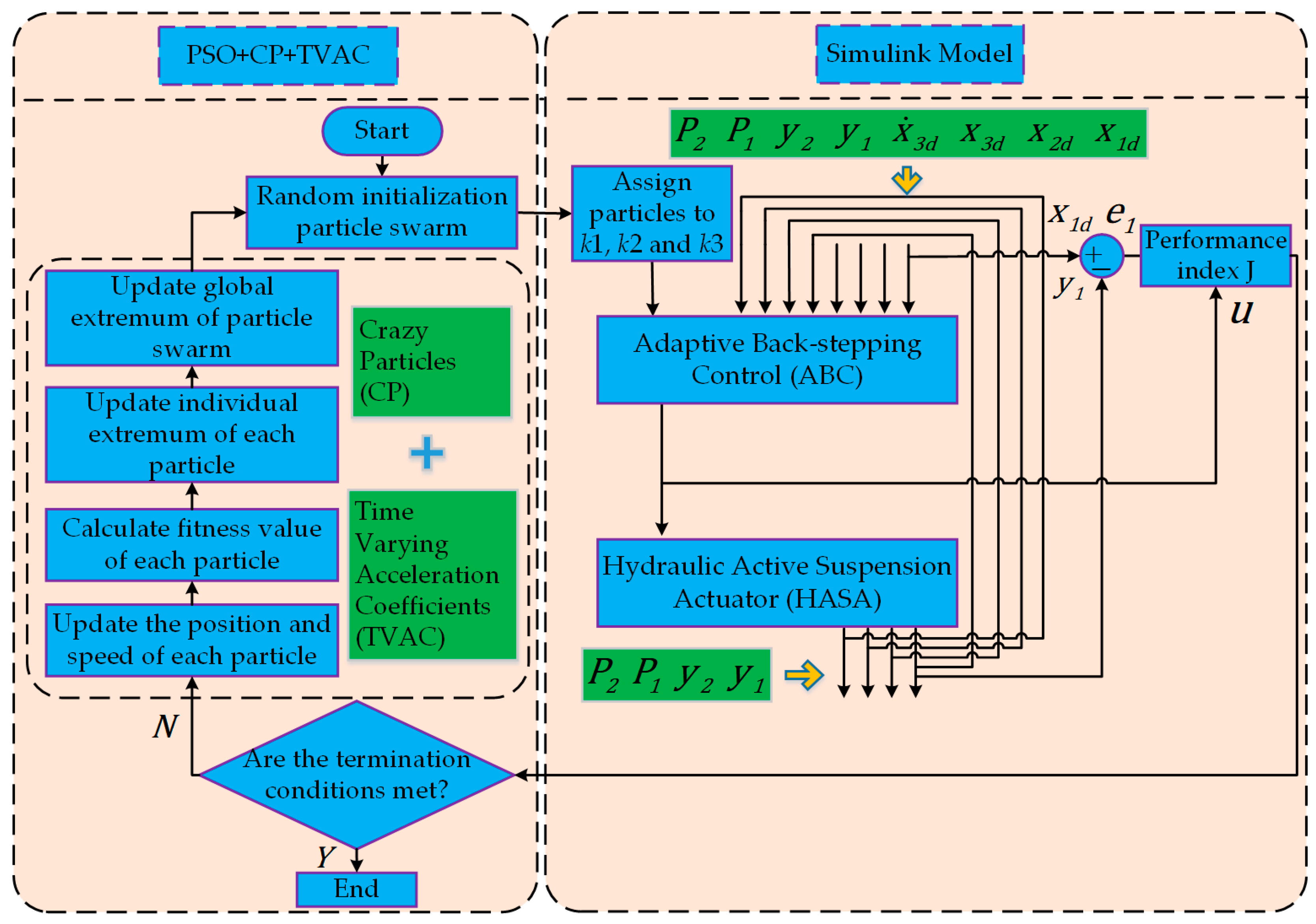
In order to verify the correctness and effectiveness of the algorithm proposed in this article, a parameter optimization flowchart as shown in Figure 2 was constructed using PSO+CP+TVAC to optimize the ABC parameters k 1 , k 2 and k 3 as examples.
Therefore, with the increasing number of iterations, the fitness value J gradually decreases, and finally the global optimal solution is obtained. The parameter values corresponding to the optimal solution are the optimal controller parameters k 1 , k 2 and k 3 .

5. Simulation Test Verification

5.1. Parameter Setting

We tested the optimization effect of the PSO, PSO+CP, and PSO+CP+ATVC algorithms on the ABC controller parameters k 1 , k 2 and k 3 . The simulation model is in discrete form, with a sampling time of 0.3 m s . The predicted displacement tracking signal is x 1 d = 0.11 s i n 2 t . In a nonlinear adaptive back-stepping controller, the adaptive gain is Γ = σ 1 , σ 2 T = 95,000 , 10 × 10 50 T . The parameter’s initial value is a 0 = 2600 , 4 × 10 12 T . The maximum value of parameter estimation is a m a x = 3000 , 10 × 10 12 T . The minimum value of parameter estimation is a m i n = 2600 , 4 × 10 12 T . Table 1 shows the hydraulic active suspension actuator’s physical properties.
The PSO parameters are set in this article to the following:  N = 80 ; M = 3 ; M A X I T E R = 100 ; m i n   J = 1 × 10 10 ; v m a x = 15 ; v m i n = 15 ; c 1 = c 2 = 2 ; x m a x = 1200 , 800 , 800 T ; x m i n = 150 , 150 , 150 T ; ω m a x = 1.2   a n d   ω m i n = 0.6 . PSO and PSO+CP do not involve the four parameters c 1 s , c 2 s , c 1 e and c 2 e , whereas PSO+CP+ATVC does not use c 1 and c 2 .

5.2. Simulation Results Analysis

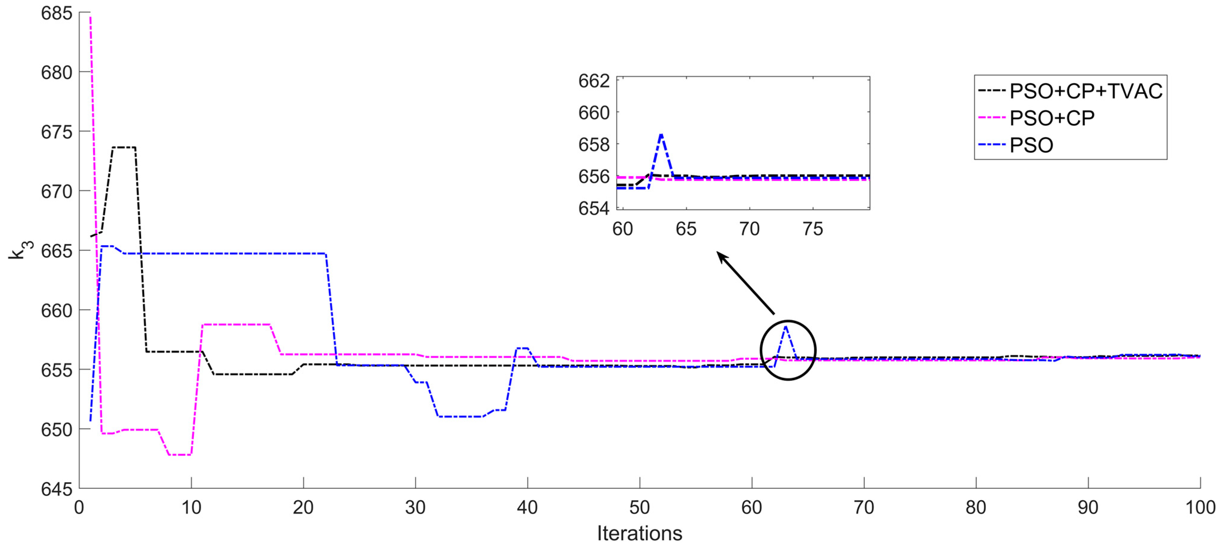
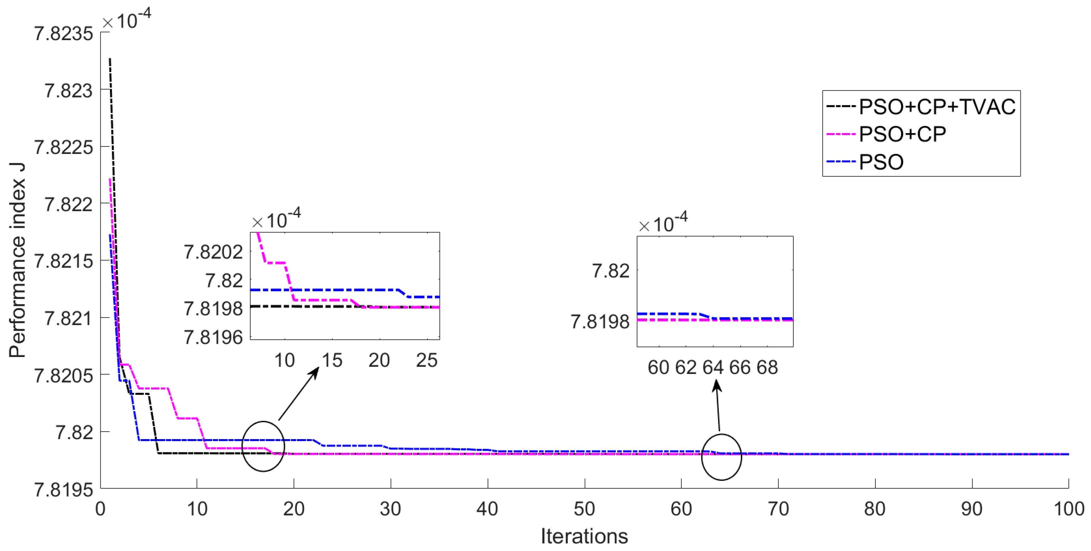
The PSO, PSO+CP, and PSO+CP+ATVC algorithms optimize the ABC controller’s parameters k 1 , k 2 and k 3 , as shown in Figure 3, Figure 4 and Figure 5. The convergence curves of PSO+CP+TVAC, PSO+CP, and PSO fitness value J are shown in Figure 6. The optimization results of parameters k 1 , k 2 and k 3 are shown in Table 2.
Figure 3, Figure 4 and Figure 5 demonstrate that the controller parameters k 1 , k 2 and k 3 obtained by the three optimization approaches converge satisfactorily before and after the 70th iteration, demonstrating the validity of the PSO+CP+ATVC methodology. Furthermore, as illustrated in Figure 6, the fitness function values optimized by the three optimization methods PSO+CP+ATVC, PSO+CP, and PSO gradually converge to J = 7.8198 × 10 4 , where PSO+CP+ATVC and PSO+CP could converge around the 17th generation, while PSO+CP+ATVC has less fluctuation. PSO converges with the slowest convergence speed in the 64th generation. As a result of adding CP and ATVC to the PSO algorithm, the problem of the PSO algorithm’s premature convergence to local optima is improved, and PSO has better self-awareness and lower social ability at the start of optimization, allowing for a faster global search. In summary, the PSO+CP+ATVC algorithm produced faster convergence, increased stability, and outperformed the competition.

5.3. Displacement Tracking Performance Comparison

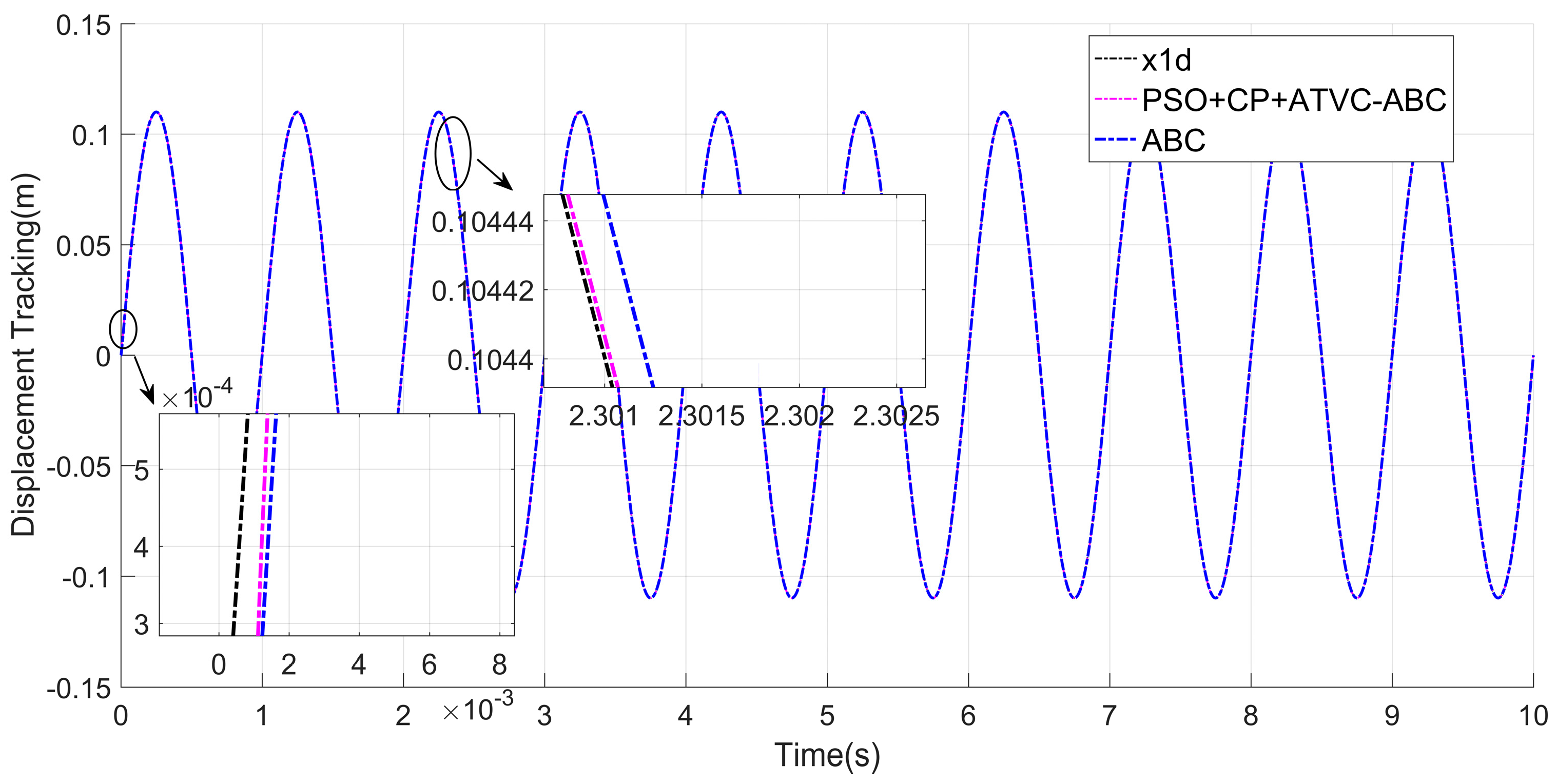
In order to verify the displacement tracking effect of PSO+CP+ATVC-ABC, the PSO+CP+ATVC parameters k 1 = 656.11 , k 2 = 656.13 and k 3 = 656.14 in Table 2 were compared and analyzed with the manually given parameters k 1 = 150 , k 2 = 158 and k 3 = 162 . The displacement tracking error between PSO+CP+ATVC-ABC and ABC is shown in Figure 7, and the displacement tracking error between PSO+CP+ATVC-ABC and ABC is shown in Figure 8.
In Figure 8, three evaluation indicators are introduced to quantitatively explain the efficiency of the PSO+CP+ATVC-ABC and ABC algorithm tracking control under steady-state conditions: the maximum tracking error e m a x , the average displacement tracking error e μ , and the displacement tracking error standard deviation e σ are all given. This is illustrated in Equations (42)–(44).
(1)
The maximum tracking error is defined as
e m a x = max i = 1,2 , p e 1 i
where e m a x is the greatest value of the error, and p denotes the amount of error data recorded.
(2)
The average value of the displacement tracking error is defined as
e μ = 1 p i = 1 p e 1 i
where e μ is the mean ability to track displacement errors.
(3)
The standard deviation of the displacement tracking error is defined as
e σ = 1 p i = 1 p e 1 i e μ 2
where e σ is the deviation of the displacement tracking error from its average value.
The displacement error data from 0.5 s to 9.5 s of steady-state operation are used in Figure 8, and the results are provided in Table 3.
Figure 7 shows the displacement tracking and Figure 8 shows the displacement tracking inaccuracy, as does Table 3. In terms of tracking accuracy and dynamic properties, it can be determined that PSO+CP+ATVC-ABC surpasses ABC with manually specified parameters.

6. Conclusions

This article researches the hydraulic active suspension actuator, develops a dynamic model of the hydraulic active suspension actuator, and develops an ABC control technique. The ABC controller lacks flexibility and reliability due to its manually entered parameters. The controller parameters are optimized by using the PSO algorithm. Because of the limitations of the PSO algorithm, such as its proclivity to lapse into local optimization and its slow convergence speed, the premature convergence of a typical particle swarm can be avoided by introducing CP to reinitialize the particle speed. ATVC is also used to improve the algorithm’s performance for both fixed and continuous acceleration constants. The simulation results validated the PSO+CP+ATVC-ABC algorithm’s accuracy and efficacy, improved the control system’s robustness, and provided a useful reference for actual parameter control applications. Furthermore, the excellent tracking accuracy achieved in this study is due to the optimization of the strong controller parameters rather than the convergence of the real-estimate parameters. In subsequent real-world applications, the convergence and tracking performance of parameter estimates should be thoroughly considered.

Author Contributions

All authors contributed to this paper: D.Z. proposed the idea and implementation methodology, reviewed and edited paper; L.W. wrote the paper, and verified the experiment process and results; X.Z. collected data; Y.Q. performed parts of experiments. All authors have read and agreed to the published version of the manuscript.

Funding

This research was funded by Regional Innovation and Development Funds of the National Natural Science Foundation of China (U20A20332), Innovative Research Groups of the Natural Science Foundation of Hebei Province (E202003174).

Institutional Review Board Statement

Not applicable.

Informed Consent Statement

Not applicable.

Data Availability Statement

Due to the nature of this research, participants in this study did not agree for their data to be shared publicly, so supporting data is not available.

Acknowledgments

This research was supported by the Key Laboratory of Special Delivery Equipment of Yanshan University.

Conflicts of Interest

The authors declare no conflict of interest.

References

  1. Hrovat, D. Survey of advanced suspension developments and related optimal control applications. Automatica 1997, 33, 1781–1817. [Google Scholar] [CrossRef]
  2. Balamurugan, L.; Jancirani, J. An Investigation on semi-active suspension damper and control strategies for vehicle ride comfort and road holding. Proc. Inst. Mech. Eng. Part I J. Syst. Control Eng. 2012, 226, 1119–1129. [Google Scholar] [CrossRef]
  3. Huang, Y.B.; Hou, H.D.; Na, J.; He, H.R.; Zhao, J.; Shi, Z.H. Output Feedback Control of Hydraulic Active Suspensions with Experimental Validation. IEEE Trans. Circuits Syst. II Express Briefs 2023, 70, 631–635. [Google Scholar] [CrossRef]
  4. Na, J.; Huang, Y.B.; Wu, X.; Liu, Y.J.; Li, Y.P.; Li, G. Active Suspension Control of Quarter-Car System with Experimental Validation. IEEE Trans. Syst. Man Cybern. Syst. 2022, 52, 4714–4726. [Google Scholar] [CrossRef]
  5. Yan, S.; Sun, W.C.; Yu, X.H.; Gao, H.J. Adaptive Sensor Fault Accommodation for Vehicle Active Suspensions via Partial Measurement Information. IEEE Trans. Cybern. 2022, 52, 12290–12301. [Google Scholar] [CrossRef]
  6. Mahyar, D.; Fateh, M.M.; Ghalehonie, M. A Fuzzy-Supervised Impedance Control for an Active Suspension System. J. Vib. Eng. Technol. 2022, 1–10. [Google Scholar] [CrossRef]
  7. Shaer, B.; Kenné, J.P.; Kaddissi, C.; Fallaha, C. A chattering-free fuzzy hybrid sliding mode control of an electro hydraulic active suspension. Trans. Inst. Meas. Control 2018, 40, 222–238. [Google Scholar] [CrossRef]
  8. Shaer, B.; Kenné, J.P.; Kaddissi, C.; Mintsa, H.A. Real-time hybrid control of electrohydraulic active suspension. Int. J. Robust Nonlinear Control 2017, 27, 4968–4991. [Google Scholar] [CrossRef]
  9. Zhao, D.X.; Liu, S.; Gong, M.D.; Sun, Z.G.; Zhang, Z.X.; Ni, T.; Yang, B.; Guo, Q.H.; Yang, M.K. Vehicle-Mounted Motion Simulation Platform Based on Active Suspension, and Control Method Therefor. U.S. Patent 11,280,703, 22 March 2022. [Google Scholar]
  10. Patil, K.S.; Gambhire, V.R. Design and development of double wishbone electro-hydraulic active suspension system. Int. J. Sci. Eng. Technol. 2014, 3, 760–764. [Google Scholar]
  11. Cytrynski, S.; Neerpasch, U.; Bellmann, R.; Danner, B. The active suspension of the new mercedes-benz GLE. ATZ Worldw. 2018, 120, 42–45. [Google Scholar] [CrossRef]
  12. Zhou, J.; Wen, C.Y. Adaptive Backstepping Control of Uncertain Systems; Springer: Berlin/Heidelberg, Germany, 2008. [Google Scholar]
  13. Wei, Y.H.; Sheng, D.; Chen, Y.Q.; Wang, Y. Fractional order chattering-free robust adaptive backstepping control technique. Nonlinear Dyn. 2019, 95, 2383–2394. [Google Scholar] [CrossRef]
  14. Wei, Y.H.; Tse, P.W.; Yao, Z.; Wang, Y. Adaptive backstepping output feedback control for a class of nonlinear fractional order systems. Nonlinear Dyn. 2016, 86, 1047–1056. [Google Scholar] [CrossRef]
  15. Yu, X.W.; Lin, Y. Adaptive backstepping quantized control for a class of nonlinear systems. IEEE Trans. Autom. Control 2017, 62, 981–985. [Google Scholar] [CrossRef]
  16. Shi, X.Y.; Cheng, Y.H.; Yin, C.; Huang, X.G.; Zhong, S.M. Design of adaptive backstepping dynamic surface control method with RBF neural network for uncertain nonlinear system. Neurocomputing 2018, 330, 490–503. [Google Scholar] [CrossRef]
  17. Yue, F.F.; Li, X.F. Robust adaptive integral backstepping control for opto-electronic tracking system based on modified LuGre friction model. ISA Trans. 2018, 80, 312–321. [Google Scholar] [CrossRef]
  18. Ma’arif, A.; Márquez-Vera, M.A.; Mahmoud, M.S.; Ladaci, S.; Çakan, A.; Nino-Parada, J. Backstepping sliding mode control for inverted pendulum system with disturbance and parameter uncertainty. J. Robot. Control 2022, 3, 86–92. [Google Scholar] [CrossRef]
  19. Xu, W.; Ismail, M.M.; Liu, Y.; Islam, M.R. Parameter optimization of adaptive flux-weakening strategy for permanent-magnet synchronous motor drives based on particle swarm algorithm. IEEE Trans. Power Electron. 2019, 34, 12128–12140. [Google Scholar] [CrossRef] [Green Version]
  20. Ghogare, M.G.; Patil, S.L.; Patil, C.Y. Experimental validation of optimized fast terminal sliding mode control for level system. ISA Trans. 2022, 126, 486–497. [Google Scholar] [CrossRef]
  21. Jin, Z.J.; Sun, X.D.; Lei, G.; Guo, Y.G.; Zhu, J.G. Sliding mode direct torque control of SPMSMs based on a hybrid wolf optimization algorithm. IEEE Trans. Ind. Electron. 2021, 69, 4534–4544. [Google Scholar] [CrossRef]
  22. Mohanty, B.; Panda, S.; Hota, P.K. Controller parameters tuning of differential evolution algorithm and its application to load frequency control of multi-source power system. Int. J. Electr. Power Energy Syst. 2014, 54, 77–85. [Google Scholar] [CrossRef]
  23. Song, J.; Zheng, W.X.; Niu, Y.G. Self-triggered sliding mode control for networked PMSM speed regulation system: A PSO-Optimized super-twisting algorithm. IEEE Trans. Ind. Electron. 2022, 69, 763–773. [Google Scholar] [CrossRef]
  24. Yin, Z.G.; Gong, L.; Du, C.; Liu, J.; Zhong, Y.R. Integrated position and speed loops under sliding mode control optimized by differential evolution algorithm for PMSM drives. IEEE Trans. Power Electron. 2019, 34, 8994–9005. [Google Scholar] [CrossRef]
  25. Yao, B.; Bu, F.P.; Reedy, J.; Chiu, G.T.-C. Adaptive robust motion control of single rod hydraulic actuators: Theory and experiments. IEEE/ASME Trans. Mechatron. 2000, 5, 79–91. [Google Scholar]
  26. Slotine, J.J.E.; Li, W.P. Applied Nonlinear Control; China Machine Press: Beijing, China, 1991. [Google Scholar]
  27. Kennedy, J.; Eberhart, R. Particle Swarm Optimization. In Proceedings of the ICNN95-International Conference on Neural Networks, Perth, Australia, 27 November–1 December 1995. [Google Scholar]
  28. Shi, Y.H.; Eberhart, R.C. Empirical Study of Particle Swarm Optimization. In Proceedings of the Congress on Evolutionary Computation, Washington, DC, USA, 6–9 July 1999. [Google Scholar]
  29. Victoire, T.A.A.; Jeyakumar, A.E. Reserve constrained dynamic dispatch of units with valve-point effects. IEEE Trans. Power Syst. 2005, 20, 1273–1282. [Google Scholar] [CrossRef]
  30. Chaturvedi, K.T.; Pandit, M.; Srivastava, L. Particle swarm optimization with crazy particles for nonconvex economic dispatch. Appl. Soft Comput. J. 2009, 9, 962–969. [Google Scholar] [CrossRef]
  31. Shukla, A.; Singh, S.N. Advanced three-stage pseudo-inspired weight-improved crazy particle swarm optimization for unit commitment problem. Energy 2016, 96, 23–36. [Google Scholar] [CrossRef]
  32. Suganthan, P.N. Particle Swarm Optimiser with Neighbourhood Operator. In Proceedings of the 1999 Congress on Evolutionary Computation-CEC99 (Cat. No.99TH8406), Washington, DC, USA, 6–9 July 1999; pp. 1958–1962. [Google Scholar]
  33. Ratnaweera, A.; Halgamuge, S.K.; Watson, H.C. Self-organizing hierarchical particle swarm optimizer with time-varying acceleration coefficients. IEEE Trans. Evol. Comput. 2004, 8, 240–255. [Google Scholar] [CrossRef]
  34. Liu, J.K. Advanced PID Control MATLAB Simulation, 4th ed.; Electronic Industry Press: Beijing, China, 2016. [Google Scholar]
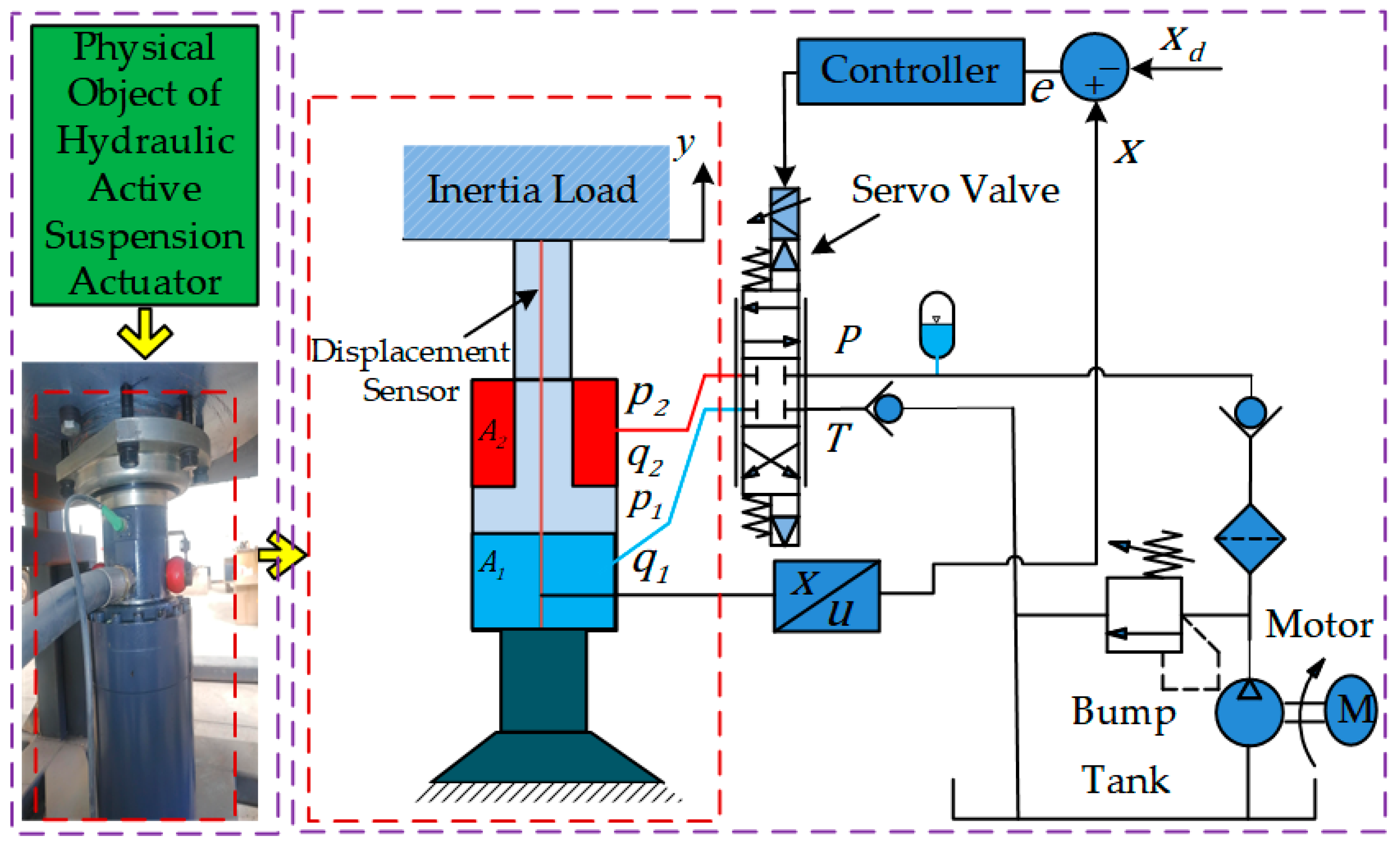
Figure 1. Hydraulic active suspension actuator system schematic diagram.
Processes 11 02020 g001
Figure 2. Flowchart showing PSO+CP+TVAC optimization of ABC parameters k 1 , k 2 and k 3 .
Processes 11 02020 g002
Figure 3. ABC controller parameter k 1 .
Processes 11 02020 g003
Figure 4. ABC controller parameter k 2 .
Processes 11 02020 g004
Figure 5. ABC controller parameter k 3 .
Processes 11 02020 g005
Figure 6. Convergence curves of PSO+CP+TVAC, PSO+CP, and PSO fitness value J .
Processes 11 02020 g006
Figure 7. PSO+CP+ATVC-ABC and ABC displacement tracking.
Processes 11 02020 g007
Figure 8. PSO+CP+ATVC-ABC and ABC displacement tracking error.
Processes 11 02020 g008
Table 1. Hydraulic active suspension actuator’s physical properties.
ParametersValuesParametersValues
m 1500   k g C d 0.7
A 1 5.67 × 10 3   m 2 W 1 = W 2 1.12 × 10 2   m
A 2 1.256 × 10 3   m 2 g 9.8   m / s 2
β e 7.0 × 10 8   P a ρ 860   k g / m 3
B p 2600   N · s / m P s 1.78 × 10 7   P a
C i 3.0 × 10 13   m 3 / s / P a P r 0   P a
V 01 = V 02 1.0 × 10 3   m 3 G 3.78 × 10 4   m 4 / s · V · N
Table 2. The k 1 , k 2 , and k 3 parameters for best results.
ParametersPSOPSO+CPPSO+CP+ATVC
k 1 656.13 656.25 656.11
k 2 656.18 656.26 656.13
k 3 656.09 655.99 656.14
Table 3. Results of displacement error data: e m a x e μ   e σ .
Controller e m a x ( m ) e μ ( m ) e σ ( m )
PSO+CP+ATVC-ABC 6.1469 × 10 6 3.6703 × 10 6 1.7773 × 10 6
ABC 6.7797 × 10 5 3.6823 × 10 5 1.9221 × 10 5
Disclaimer/Publisher’s Note: The statements, opinions and data contained in all publications are solely those of the individual author(s) and contributor(s) and not of MDPI and/or the editor(s). MDPI and/or the editor(s) disclaim responsibility for any injury to people or property resulting from any ideas, methods, instructions or products referred to in the content.