Article

Observer-Based Control of Inductive Wireless Power Transfer System Using Genetic Algorithm

by
Mahmoud Abdelrahim
1,2,*,† and
Dhafer Almakhles
1,*,†
1
Renewable Energy Lab, College of Engineering, Prince Sultan University, Riyadh 11586, Saudi Arabia
2
Department of Mechatronics Engineering, Faculty of Engineering, Assiut University, Assiut 71515, Egypt
*
Authors to whom correspondence should be addressed.
These authors contributed equally to this work.
Processes 2023, 11(6), 1859; https://doi.org/10.3390/pr11061859
Submission received: 18 May 2023 / Revised: 31 May 2023 / Accepted: 17 June 2023 / Published: 20 June 2023
(This article belongs to the Topic Modeling, Optimization, and Control of Energy Systems)

Abstract

:
In this paper, we studied the feedback stabilization of an inductive power transfer system based on available output measurement. The proposed controller relies on a full-order state observer in order to estimate the unmeasured state. The control design problem is challenging due to the large dimension of the closed-loop system, which requires too many tuning parameters to be determined when conventional control methods are employed. To solve this issue, we propose an LQR methodology based on a genetic algorithm such that the weighing coefficients of the cost function matrices can be automatically computed in an optimized manner. The proposed approach combines the method of eigenstructure assignment and the LQR technique in order to design both the controller and the observer gain matrices. The design methodology provides a systematic way to compute the parameters of the LQR technique for a wireless power transfer system in an optimized manner, which can be a useful design tool for many other applications. The effectiveness of the approach was verified by numerical simulation on the dynamic model of the wireless power transfer system. The results show that the proposed design outperforms conventional design methods in terms of a better performance and reduced design iterations effort.

1. Introduction

The development of electric vehicles (EVs) has attracted great technological and scientific attentions in the past few decades due to the increasing global need for alternative transportation solutions to traditional vehicles that are based on internal combustion engines. This global need is motivated by the harmful environmental impacts caused by combustion engines, such as pollution and its contribution in the global warming and climate change phenomena. Moreover, energy sources from fossil fuels are another concern of the community since these energy sources are scarce and not renewable. In this context, EV technologies are strongly supported nowadays as a green solution for transportation [1,2]. The EV system consists of four main components, which are: electric motor, battery, inverter and onboard charger. The efficiency of these components greatly affects the EV performance and its convenience of use by the drivers. The charging technology of EV batteries represents a great challenge and is still far from being mature compared to fuel-based combustion engines [3,4]. The charging methods of EV batteries currently available can be classified into plug-in (conductive) charging and wireless (inductive) charging. The latter technology is currently receiving much research interest due to its advantages compared to conductive charging in terms of safety, cost, convenience and installation. The idea of inductive charging is to enable the flow of power from the transmitter to receiver in a contactless manner, i.e., wireless power transfer (WPT). Although the idea is appealing, the implementation of WPT involves some challenges, such as a slow time of charging and complex control methods. In this paper, we focused on the investigation of control design methodologies for WPT systems [5,6,7,8,9].
Different control techniques have been developed in the literature for the WPT systems, e.g., [10,11,12,13,14,15,16,17,18,19,20,21,22,23] and the references therein. Most existing approaches focus on the control of the primary or secondary side of the WPT system only. Few works of the literature have considered both sides in the control design problem [24,25,26,27]. The technique of [24] derived an insightful state space model to describe the behavior of a bidirectional inductive power transfer system. Then, the obtained model was mapped onto the frequency domain to compute the controller gains. The approach of [26] extended the result of [24] to the case of a multipickup bidirectional inductive power transfer system. The authors of [25] developed a state space model taking into account Internet of Things (IoT) communications between sensors and controllers. The proposed control design in [25] was based on a Kalman filter to estimate the unknown state variables. The authors of [27] presented a state space model for a bidirectional inductive power transfer system under different operating conditions, such as harmonics and parameters sensitivities. However, none of the previously mentioned works considered optimized feedback control for the bidirectional inductive power transfer system, to the best of our knowledge. Note that the control design is very challenging due to the large dimension of the closed-loop system. Hence, conventional control techniques such as pole placement and LQR require the tuning of several parameters, which is not trivial and may not lead to a satisfactory performance.
We considered the problem of the output feedback control of an inductive WPT system. A full-order observer was first synthesized to estimate the unmeasured state variables and then the estimated state was fed to the controller to stabilize the closed-loop system. In order to determine the control gains, we exploited the genetic algorithm technique such that those gains can be determined systematically in an optimized fashion. The idea of computing the LQR weighing elements of the cost function matrices has been considered in the literature for different applications, such as aircraft pitch control [28], Inverted pendulum [29], a boost converter [30], an active suspension system [31] and an engine throttle valve system [32]. However, none of these solutions have been adapted to dynamical systems with large dimensions such as the WPT system. The effectiveness of the approach was demonstrated in a simulation and the performance was compared with the pole placement and manually tuned LQR methods. The results show that the closed-loop performance and the control design effort under the proposed scheme is greatly improved compared to the previously mentioned methods. The approach is applicable to any linear time-invariant system provided that the plant and the controller dynamics are controllable and observable.
The main contributions of this paper are summarized below:
  • A novel design methodology for a bidirectional inductive power transfer system is proposed based on eiegnstructure assignment and LQR methods;
  • The parameters of the controller are optimized by using the genetic algorithm;
  • The effectiveness of the approach is supported by a simulation comparison with manually tuned LQR.
Note that our design approach belongs to model-based control techniques based on a state-space model of the inductive power transfer system. If the model is not available, data-driven approaches can be employed; see, e.g., [33,34,35,36,37].
The remainder of this paper is organized as follows. The state space model and the problem are formulated in Section 2. The control design approach is explained in Section 3. The simulation results and comparisons with conventional control approaches are also presented in Section 4. Conclusions are given in Section 5.

2. Problem Formulation

The bi-directional inductive WPT consists of two separate circuits: a primary side and secondary side. The primary circuit is usually connected to the grid whereas the secondary circuit is connected to the load (EV batter in this case). The energy is transferred from the primary side to the secondary side over the air gap via inductive couplings; see [24] for more detail.
The dynamic model of the WPT system is given by [24,25]
d d t i p i ( t ) = R p i L p i i p i ( t ) 1 L p i υ c p i ( t ) + 1 L p i υ p t + 1 L p i υ p i ( t ) d d t υ c p i ( t ) = 1 C p i i p i ( t ) d d t υ p t ( t ) = 1 C T i p i ( t ) 1 C T i T ( t ) d d t i T ( t ) = γ L T υ p t ( t ) γ R T L T i T ( t ) γ β υ s t ( t ) γ β R s i i s i ( t ) 1 L s o υ s o ( t ) d d t i s o ( t ) = R s o L s o i s o ( t ) 1 L s o υ c s o ( t ) + 1 L s o υ s t ( t ) d d t υ c s o ( t ) = 1 C s o i s o ( t ) d d t υ s t ( t ) = 1 C s i s o ( t ) + 1 C s i s i ( t ) d d t i s i ( t ) = γ β υ p t ( t ) γ β R T i T ( t ) γ L s i υ s t ( t ) γ R s i L s i i s i ( t ) ,
where
i p i ( t ) is the current through the inductor L p i ;
υ c p i ( t ) is the voltage across the capacitor C p i ;
υ p t ( t ) is the voltage across the capacitor C T ;
i T ( t ) is the current through the inductor L T ;
i s o ( t ) is the current through the inductor L s o ;
υ c s o ( t ) is the voltage across the capacitor C s o ;
υ s t ( t ) is the voltage across the capacitor C s ;
i s i ( t ) is the current through the inductor L s i ;
υ p i ( t ) is the input voltage applied at the primary side;
υ s o ( t ) is the voltage at the secondary side.
We assume that only the current i T ( t ) through track inductor L t and the current i s o ( t ) through the pick-up side inductor L s o are available for measurement. Also, we assume that the WPT system is controlled by two control signals, namely the input voltage applied at the primary side, denoted by υ p i , and the voltage at the pick-up side, denoted by υ s o . Then, the state space model of the WPT system is given by
x ˙ ( t ) = A x ( t ) + B u ( t ) y ( t ) = C x ( t ) ,
where x ( t ) : = ( i p i , υ c p i , υ p t , i T , i s o , υ c s o , υ s t , i s i ) is the state vector, u ( t ) : = ( υ p i , υ s o ) is the control signal and y ( t ) : = ( i T , i s o ) is the measured output. The matrices A , B , C are given by
A = R p i L p i 1 L p i 1 L p i 0 0 0 0 0 1 C p i 0 0 0 0 0 0 0 1 C T 0 0 1 C T 0 0 0 0 0 0 γ L T γ R T L T 0 0 γ β γ β R s i 0 0 0 0 R s o L s o 1 L s o 1 L s o 0 0 0 0 0 1 C s o 0 0 0 0 0 0 0 1 C s 0 0 1 C s 0 0 γ β γ β R T 0 0 γ L s i γ R s i L s i B = 1 L p i 0 0 0 0 0 0 0 0 0 0 0 1 L s o 0 0 0 T , C = 0 0 0 1 0 0 0 0 0 0 0 0 1 0 0 0 .
Our objective is to design a stabilizing output feedback law u such that the closed-loop stability is guaranteed in an optimal sense using only the output feedback measurement y.

3. Control Design

Since only part of the state can be measured, we stabilized the system by means of a Luenberger full-order observer, which takes the following form:
x ^ ˙ ( t ) = A x ^ ( t ) + B u ( t ) + L ( y ( t ) C x ^ ( t ) ) u ( t ) = K x ^ ( t ) ,
where x ^ is the estimated state, L is the observer gain matrix and K is the controller gain matrix. Define the estimation error
e ( t ) = x ( t ) x ^ ( t ) .
Consequently, in view of (2) and (4), we have that
e ˙ ( t ) = A x ( t ) + B u ( t ) A x ^ ( t ) B u ( t ) L ( y ( t ) C x ^ ( t ) ) = ( A L C ) x ( t ) ( A L C ) x ^ ( t ) = ( A L C ) e ( t ) .
Then, in view of (2) and (6), it holds that
x ˙ ( t ) e ˙ ( t ) = A B K B K 0 A L C x ( t ) e ( t ) .
Consequently, assuming that the pair ( A , B ) is controllable and the pair ( A , C ) is observable, the stability of the closed-loop system ( x ( t ) , e ( t ) ) can be guaranteed if the gain matrices K , L are designed such that A B K and A L C are Hurwitz. In what follows, we explain how to design such gain matrices by different methods.

3.1. Eigenstructure Assignment

A simple approach used to design the controller gain K is the pole placement technique. It is important to note that system (2) is not a single-input–single-output (SISO) system and hence the Ackerman formula cannot be applied to compute the gain matrix K. Alternatively, the eigenstructure assignment technique is employed as follows.
Consider system (2) with x R n and u R m . Let Λ : = { λ 1 , λ 2 , , λ n } denote the set of desired eigenvalues, which could be real or self-conjugate complex numbers. Then, we need to design K such that the eigenvalues of A B K are located at λ 1 , λ 2 , , λ n . Consequently, it holds that
( A B K ) ν i = λ i ν i , i = 1 , 2 , , n ,
where ν i is the eigenvector corresponding to the eigenvalue λ i . By re-arranging the terms, we obtain
( λ i I n A ) ν i = B K ν i
or
λ i I n A B ν i K ν i = 0 ,
where I n is an n × n identity matrix. We define
S λ i : = [ λ i I n A | B ] R λ i : = N λ i M λ i
such that the columns of R λ i form a basis for the null space of S λ i .
The following result provides necessary and sufficient conditions for the existence of the gain matrix K that satisfies (8) and how to compute this gain matrix K.
Theorem 1
([38]). Let { λ 1 , λ 2 , , λ n } be a self-conjugate set of distinct complex numbers. There exists a real ( m × n ) matrix K such that
( A B K ) ν i = λ i ν i , i = 1 , 2 , , n
if and only if, for each i,
  • { ν 1 , ν 2 , , ν n } is a linearly independent set in C N , the space of complex N-vectors;
  • ν i = ν j * when λ i = λ j * , where the a * denotes the conjugate of given a (complex vector or scalar);
  • ν i span { N λ i } .
Also, if K exists and rank ( B ) = m , then K is unique and is computed by using the obtained submatrices N λ i and M λ i .
From Theorem 1, we conclude that the right eigenvectors ν i , i = 1 , , n are constructed from the columns of null space matrix N λ i for the closed-loop system [ λ i I n A | B ] . Then, the gain matrix K can be computed as follows. Define first the following matrices:
V = [ ν 1 ν 2 ν n ] N = [ N λ 1 N λ 2 N λ n ] M = [ M λ 1 M λ 2 M λ n ] .
Then, in view of (10), (11), we have that, for all i 1 , 2 , , n ,
λ I A B V K V = 0 ,
and
S λ : = [ λ I A | B ] R λ : = N M ,
where I is a block diagonal matrix of I n matrices as the diagonal blocks. Then, by comparison, we have
V = N K V = M .
Then, we obtain
K = M V 1 = M N 1
and since the columns of V are linearly intendant, the existence of N 1 is ensured.
Hence, the approach of eigenstructure assignment consists of first finding a basis ( N λ i , M λ i ) of the null space of λ i I n A for all i = 1 , 2 , , n to form the matrix N and M. Then, the gain matrix K is computed from (16). A similar approach can be followed to compute the observer gain matrix L in (4) for the dual system
z ˙ ( t ) = A z z ( t ) + B z u ( t ) y ( t ) = C z z ( t )
with A z = A T , B z = C T and C z = B T .
Although the eigenstructure assignment approach is straightforward, the selection of the desired eigenvalues is not trivial in particular if the system has multiple closed-loop poles. In our case, the system has eight eigenvalues to be specified, which requires a tremendous effort of iterations until a satisfactory response is obtained.

3.2. Linear Quadratic Regulator

To overcome the previous issue, optimal locations for the closed-loop eigenvalues can be computed by using the LQR technique.
First, let us assume that the full-state measurement is available, i.e., y = x . Then, we can design an LQR controller to strike a balance between the state response and the control effort by using the following quadratic cost function:
J 1 = 0 x T Q 1 x + u T R 1 u d t ,
where Q 1 , R 1 are symmetric positive definite diagonal matrices. Then, by solving the algebraic Riccati equation
A T P 1 + P 1 A + Q 1 P 1 B R 1 1 B T P 1 = 0
the optimal state feedback law is given by u = K x p with [39]
K = R 1 1 B T P 1 .
Now, we consider that only an output y is measured but not the full state. Then, we employ the state observer in (4) to estimate the state. Since the wind turbine is affected by external disturbance, we apply the Kalman filter to design the observer gain L by solving the following algebraic Riccati equation:
P 2 A T + A P 2 + Q 2 P 2 C T R 2 1 C P 2 = 0 ,
where Q 2 , R 2 are symmetric positive definite diagonal matrices. Consequently, the observer gain (Kalman gain) L is given by [39]
L = P 2 C T R 2 1 .
It can be noted from the previous case that the control performance was restricted a priori by the selected matrices Q 1 = C T C and Q 2 = B B T . On the other hand, if we tried to pick those matrices freely, this would require a large amount of iterations for the entries in the matrices Q 1 and Q 2 . To avoid this issue, we exploited the genetic algorithm technique in order to optimize the values of all the weighing matrices Q 1 , Q 2 , R 1 , R 2 . The approach can be summarized in Figure 1. The genetic algorithm is inspired by biological behaviors where a group of an initial population of chromosomes is randomly generated such that each chromosome corresponds to a solution of the optimization problem [40]. The desired performance of the system is formulated in terms of a fitness function (objective function) and the behavior of the current population is assessed based on such fitness function. Then, the corresponding value of the controller gain K is obtained. The genetic algorithm is terminated when the objective function reaches its minimum or when the population size exceeds the maximum value.
We applied this optimized method to compute the matrices Q 1 and R 1 for the cost function of the controller gain K. Then, in order to ensure a fast estimation of the observer, we applied the pole placement method to compute the observer gain L such that the eigenvalues of the observer that are to be ( A L C ) are greater than those of the controller matrix ( A B K ) .

4. Simulation Results

To better justify the approach, we first present the results under the pole placement and the manually tuned LQR and then we show the results of the proposed technique. The simulation results were performed with the parameters values given in Table 1 below [25].

4.1. Eigenstructure Assignment

For the eigenstructure assignment technique, we chose the desired eigenvalues to be λ c = ( 1 , 2 , 3 , 4 , 3 , 2 , 1 , 5 ) , and we obtained
K = 0.4609 1.0000 3.0325 0.4438 0.0117 0.0000 0.0008 0.0118 0.0122 0.0000 0.0009 0.0122 0.4186 1.0000 2.9678 0.3955 .
Then, in order to provide fast state estimation by the observer, we can take the desired eigenvalues locations of the observer, i.e., A L C , to be λ o = 4 λ d , which leads to
L = 42 370 778 43 0.1 0 0.3 0.3 0.5 0.1 0.1 0.5 39 394 1178 75 T .
The closed-loop response is shown in Figure 2, Figure 3, Figure 4 and Figure 5 for the state trajectories x 1 , , x 8 and the estimated states x ^ 1 , , x ^ 8 , respectively. The generated control input is shown in Figure 6. We note that all states and control inputs exhibit huge overshoot, which is not acceptable in practice.

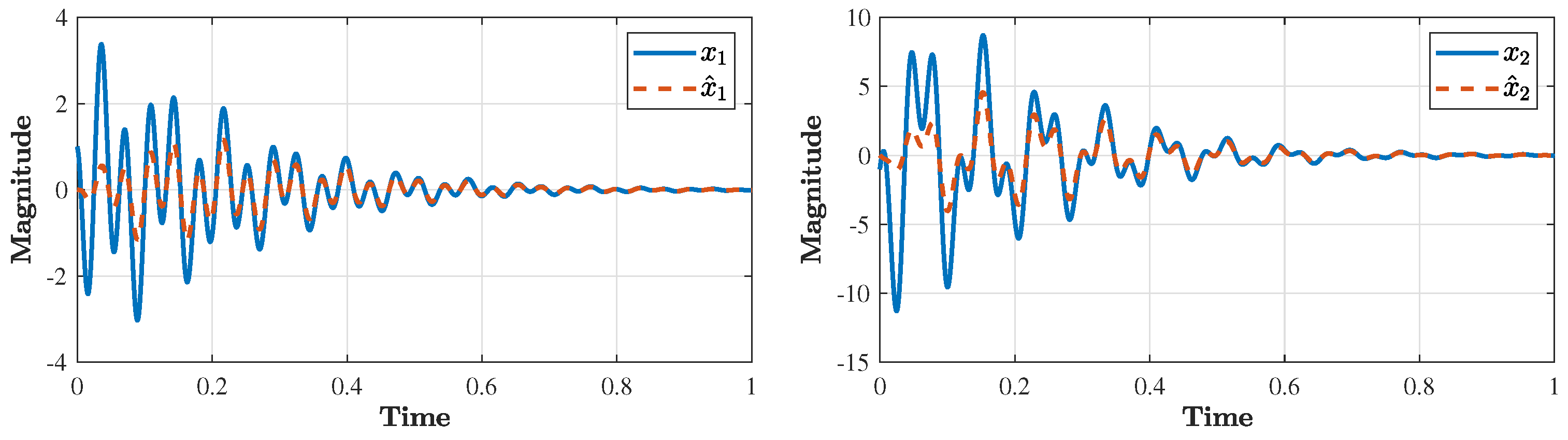
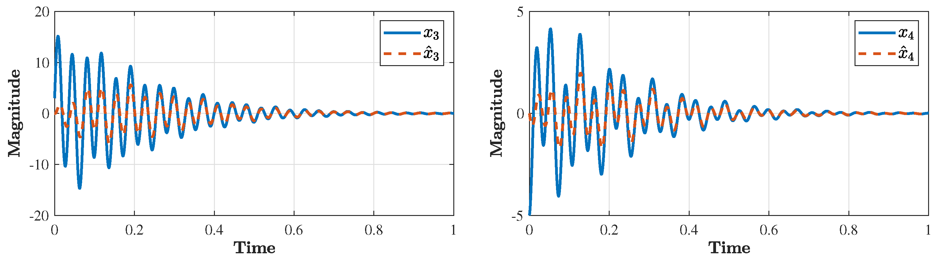
4.2. Manually Tuned LQR

Since the controller is based only on output feedback, the matrices Q 1 and Q 2 can be chosen to be Q 1 = C T C and Q 2 = B B T whereas the matrices R 1 and R 2 can be arbitrarily defined until a satisfactory performance is obtained. We obtain
K = 1.3618 0.0000 0.0507 0.0089 0.0002 0.0001 0.0001 0.0002 0.0002 0.0001 0.0001 0.0001 0.9537 0.0000 0.0018 0.0001 .
Then, in order to provide fast state estimation by the observer, we can take the desired eigenvalues locations of the observer, i.e., A L C , to be λ o = 4 λ d , which leads to
L = 0.5705 10.0878 10.2527 29.2793 0.0039 0.0008 0.0284 0.0059 0.0019 0.0176 0.0186 0.0039 20.6067 0.0000 0.7263 0.0023 T .
The closed-loop response is shown in Figure 7, Figure 8, Figure 9 and Figure 10 for the state trajectories x 1 , , x 8 and the estimated states x ^ 1 , , x ^ 8 , respectively. The generated control input is shown in Figure 11. We note that the peak overshoot has been greatly reduced compared to the response in Figure 2, Figure 3, Figure 4, Figure 5 and Figure 6; however, the state trajectories and the control inputs exhibit oscillations, which is also not desirable in practice. This motivates our proposed approach in the next section.

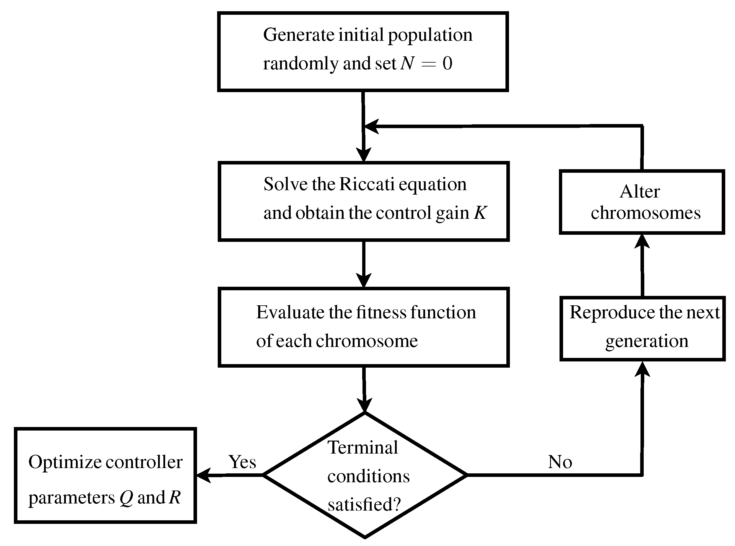
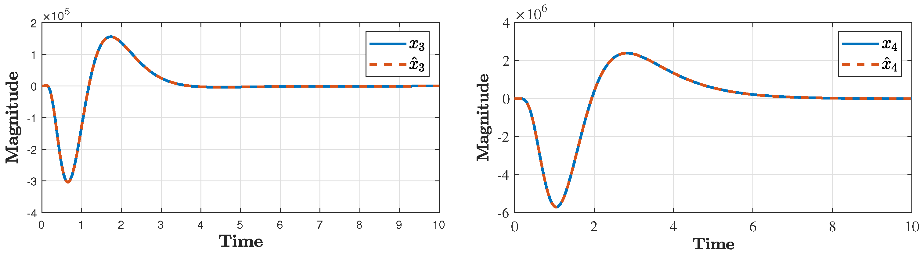
4.3. Automatic Tuning of LQR Based on Genetic Algorithm

To avoid the manual tuning of the matrices Q and R for the LQR control method, we used here the genetic algorithm described in Figure 1 to compute these matrices in an optimized manner. We set the number of individuals to 100, the number of chromosomes to 10 and the number of generations to 100, and we considered the following fitness function F T :
F T = 0.5 T r + 0.5 T s + 0.01 M o ,
where T r R 0 is the rise time, T s R 0 is the settling time and M o R 0 is the maximum overshoot. Hence, the fitness function (27) reflects priorities to significantly reduce the rise and the settling times. We obtain the following matrices for the LQR controller:
Q 1 = 0.8135 0 0 0 0 0 0 0 0 0.1531 0 0 0 0 0 0 0 0 0.1036 0 0 0 0 0 0 0 0 0.9465 0 0 0 0 0 0 0 0 0.4924 0 0 0 0 0 0 0 0 0.7482 0 0 0 0 0 0 0 0 0.3109 0 0 0 0 0 0 0 0 0.0077 .
R 1 = 0.0180 0 0 0.0294 ,
which corresponds to the eigenvalues of λ ( A B K ) = ( 216.55 ± 206.86 i , 33.73 ± 172 i , 54.35 ± 86.38 i , 44.69 ± 88.68 i ) with the gain matrix
K = 25.1523 5.2531 7.8129 12.3159 0.0017 0.0007 0.0010 0.0072 0.0001 0.0002 0.0000 0.0002 7.2111 1.0594 0.3353 1.8719 .
Then, we took the eigenvalues of the observer to be λ ( A L C ) = 4 λ ( A B K ) and computed the corresponding value of L. The closed-loop response is shown in the figures below. We note that the dynamic behavior of the closed-loop system has been enormously improved in terms of the maximum overshoot and the settling time compared to the cases of pole placement and conventional LQR.
To conclude, the simulation clearly reflects that the manual tuning of control parameters is tedious and requires too many iterations until a satisfactory response can be obtained, particularly when the dimension of systems is as large as the dynamic model of the bidirectional inductive wireless power transfer system. For instance, for the control technique of eigenstructure assignment, we need to specify the location of eight closed-loop eigenvalues. Moreover, for the manually tuned LQR method, we need to identify 10 entry values of the Q and R matrices, which is further difficult to determine. On the other hand, for genetic-based LQR control, the parameters of the Q and R matrices are computed offline in an optimized manner, which results in a superior performance for the state and control trajectories as shown in Figure 12, Figure 13, Figure 14, Figure 15 and Figure 16.

5. Conclusions

We studied the problem of output feedback control for a bidirectional inductive wireless power transfer system. First, a full-order observer was constructed based on a Luenberger state estimator. Then, an observer-based controller was synthesized to ensure the stability of the closed-loop system. The proposed approach combines tools from eignenstructure assignment and LQR methods. Due to the large system dimension, the main challenge in this study is how to find optimized values for the LQR controller to achieve a satisfactory output response. The problem was solved by using a genetic algorithm to automatically tune the parameters of the LQR controller. A simulation comparison was conducted to highlight the benefit of the proposed method compared to manual tuning. The results show that the proposed method is superior to the previously mentioned conventional techniques.
Future work will focus on the networked control analysis and design for the wireless power transfer system.

Author Contributions

Conceptualization, M.A.; methodology, M.A.; formal analysis, D.A.; investigation, D.A.; Simulation, M.A.; writing—original draft preparation, M.A.; writing—review and editing, D.A. All authors have read and agreed to the published version of the manuscript.

Funding

This work was supported by Prince Sultan University, Riyadh, Saudi Arabia.

Data Availability Statement

Not applicable.

Acknowledgments

The authors would like to acknowledge the support of Prince Sultan University for paying the Article Processing Charges (APC) of this publication.

Conflicts of Interest

The authors declare no conflict of interest.

References

  1. Sun, X.; Li, Z.; Wang, X.; Li, C. Technology Development of Electric Vehicles: A Review. Energies 2020, 13, 90. [Google Scholar] [CrossRef] [Green Version]
  2. Sanguesa, J.A.; Torres-Sanz, V.; Garrido, P.; Martinez, F.J.; Marquez-Barja, J.M. A Review on Electric Vehicles: Technologies and Challenges. Smart Cities 2021, 4, 372–404. [Google Scholar] [CrossRef]
  3. Franke, T.; Görges, D.; Arend, M. The Energy Interface Challenge. Towards Designing Effective Energy Efficiency Interfaces for Electric Vehicles. In Proceedings of the 11th International Conference on Automotive User Interfaces and Interactive Vehicular Applications, Utrecht, The Netherlands, 21–25 September 2019; pp. 35–48. [Google Scholar]
  4. Pan, Z.; Shieh, S.Y.; Li, B. Battery State-of-Charge Pulse-and-Glide Strategy Development of Hybrid Electric Vehicles for VTS Motor Vehicle Challenge. In Proceedings of the 2018 IEEE Vehicle Power and Propulsion Conference (VPPC), Chicago, IL, USA, 27–30 August 2018; pp. 1–7. [Google Scholar]
  5. Rayan, B.A.; Subramaniam, U.; Balamurugan, S. Wireless Power Transfer in Electric Vehicles: A Review on Compensation Topologies, Coil Structures, and Safety Aspects. Energies 2023, 16, 3084. [Google Scholar] [CrossRef]
  6. El-Shahat, A.; Ayisire, E.; Wu, Y.; Rahman, M.; Nelms, D. Electric Vehicles Wireless Power Transfer State-of-The-Art. Energy Procedia 2019, 162, 24–37. [Google Scholar] [CrossRef]
  7. Amjad, M.; Farooq-i-Azam, M.F.; Ni, Q.; Dong, M.; Ansari, E.A. Wireless charging systems for electric vehicles. Renew. Sustain. Energy Rev. 2022, 167, 112730. [Google Scholar] [CrossRef]
  8. Li, S.; Mi, C.C. Wireless Power Transfer for Electric Vehicle Applications. IEEE J. Emerg. Sel. Top. Power Electron. 2015, 3, 4–17. [Google Scholar]
  9. Savari, G.F.; Sathik, M.J.; Raman, L.A.; El-Shahat, A.; Hasanien, H.M.; Almakhles, D.; Aleem, S.H.A.; Omar, A.I. Assessment of charging technologies, infrastructure and charging station recommendation schemes of electric vehicles: A review. Ain Shams Eng. J. 2023, 14, 101938. [Google Scholar] [CrossRef]
  10. Alkasir, A.; Abdollahi, S.E.; Abdollahi, S.R.; Wheeler, P. Enhancement of dynamic wireless power transfer system by model predictive control. IET Power Electron. 2022, 15, 67–79. [Google Scholar] [CrossRef]
  11. Hou, C.; Zhao, Q. Optimal Control of Wireless Powered Edge Computing System for Balance Between Computation Rate and Energy Harvested. IEEE Trans. Autom. Sci. Eng. 2023, 20, 1108–1124. [Google Scholar] [CrossRef]
  12. Solimene, L.; Corti, F.; Musumeci, S.; Ragusa, C.S.; Reatti, A. Magnetic Control of LCC-S Compensated Wireless Power Transfer System. In Proceedings of the 2022 International Symposium on Power Electronics, Electrical Drives, Automation and Motion (SPEEDAM), Sorrento, Italy, 22–24 June 2022; pp. 160–165. [Google Scholar] [CrossRef]
  13. Dai, X.; Hua, X.; Sun, S.; Sun, Y. Dynamic output feedback control for wireless power transfer systems. Asian J. Control 2023. [Google Scholar] [CrossRef]
  14. Deng, Q.; Li, Z.; Liu, J.; Li, S.; Luo, P.; Cui, K. Data-Driven Modeling and Control Considering Time Delays for WPT System. IEEE Trans. Power Electron. 2022, 37, 9923–9932. [Google Scholar] [CrossRef]
  15. Liu, Y.; Liu, F.; Feng, H.; Zhang, G.; Wang, L.; Chi, R.; Li, K. Frequency tracking control of the WPT system based on fuzzy RBF neural network. Int. J. Intell. Syst. 2022, 37, 3881–3899. [Google Scholar] [CrossRef]
  16. Venkatesan, M.; Rajamanickam, N.; Vishnuram, P.; Bajaj, M.; Blazek, V.; Prokop, L.; Misak, S. A Review of Compensation Topologies and Control Techniques of Bidirectional Wireless Power Transfer Systems for Electric Vehicle Applications. Energies 2022, 15, 7816. [Google Scholar] [CrossRef]
  17. Ahn, D.; Kim, S.; Moon, J.; Cho, I.K. Wireless Power Transfer with Automatic Feedback Control of Load Resistance Transformation. IEEE Trans. Power Electron. 2016, 31, 7876–7886. [Google Scholar] [CrossRef]
  18. Zhou, Z.; Zhang, L.; Liu, Z.; Chen, Q.; Long, R.; Su, H. Model Predictive Control for the Receiving-Side DC-DC Converter of Dynamic Wireless Power Transfer. IEEE Trans. Power Electron. 2020, 35, 8985–8997. [Google Scholar] [CrossRef]
  19. Wang, Z.; Wei, X.; Dai, H. Design and Control of a 3 kW Wireless Power Transfer System for Electric Vehicles. Energies 2016, 9, 10. [Google Scholar] [CrossRef]
  20. Zhong, W.; Hui, S.Y.R. Charging Time Control of Wireless Power Transfer Systems without Using Mutual Coupling Information and Wireless Communication System. IEEE Trans. Ind. Electron. 2017, 64, 228–235. [Google Scholar] [CrossRef]
  21. Zhu, H.; Zhang, B.; Wu, L. Output Power Stabilization for Wireless Power Transfer System Employing Primary-Side-Only Control. IEEE Access 2020, 8, 63735–63747. [Google Scholar] [CrossRef]
  22. Wei, Z.; Zhang, B.; Shu, X.; Rong, C. A Wireless Power Transfer System with Hybrid Control for Constant Current and Voltage Output. IEEE J. Emerg. Sel. Top. Power Electron. 2022, 10, 6317–6331. [Google Scholar] [CrossRef]
  23. Gao, X.; Cao, W.; Yang, Q.; Wang, H.; Wang, X.; Jin, G.; Zhang, J. Parameter optimization of control system design for uncertain wireless power transfer systems using modified genetic algorithm. CAAI Trans. Intell. Technol. 2022, 7, 582–593. [Google Scholar] [CrossRef]
  24. Swain, A.K.; Neath, M.J.; Madawala, U.K.; Thrimawithana, D.J. A Dynamic Multivariable State-Space Model for Bidirectional Inductive Power Transfer Systems. IEEE Trans. Power Electron. 2012, 27, 4772–4780. [Google Scholar] [CrossRef]
  25. Rana, M.M.; Xiang, W.; Wang, E.; Li, X.; Choi, B.J. Internet of Things Infrastructure for Wireless Power Transfer Systems. IEEE Access 2018, 6, 19295–19303. [Google Scholar] [CrossRef]
  26. Swain, A.K.; Devarakonda, S.; Madawala, U.K. Modeling, Sensitivity Analysis, and Controller Synthesis of Multipickup Bidirectional Inductive Power Transfer Systems. IEEE Trans. Ind. Inform. 2014, 10, 1372–1380. [Google Scholar] [CrossRef]
  27. Thrimawithana, D.J.; Madawala, U.K. A Generalized Steady-State Model for Bidirectional IPT Systems. IEEE Trans. Power Electron. 2013, 28, 4681–4689. [Google Scholar] [CrossRef]
  28. Vishal; Ohri, J. GA tuned LQR and PID controller for aircraft pitch control. In Proceedings of the 2014 IEEE 6th India International Conference on Power Electronics (IICPE), Kurukshetra, India, 8–10 December 2014; pp. 1–6. [Google Scholar]
  29. Wongsathan, C.; Sirima, C. Application of GA to design LQR controller for an Inverted Pendulum System. In Proceedings of the 2008 IEEE International Conference on Robotics and Biomimetics, Bangkok, Thailand, 22–25 February 2009; pp. 951–954. [Google Scholar]
  30. Habib, M.; Khoucha, F.; Harrag, A. GA-based robust LQR controller for interleaved boost DC-DC converter improving fuel cell voltage regulation. Electr. Power Syst. Res. 2017, 152, 438–456. [Google Scholar] [CrossRef]
  31. Yu, W.; Li, J.; Yuan, J.; Ji, X. LQR controller design of active suspension based on genetic algorithm. In Proceedings of the 2021 IEEE 5th Information Technology, Networking, Electronic and Automation Control Conference (ITNEC), Xi’an, China, 15–17 October 2021; Volume 5, pp. 1056–1060. [Google Scholar]
  32. Abdelrahim, M.; Mabrok, M.A.; Darwish, M.A.H. Networked control design for an engine throttle valve system. Int. J. Control 2022, 1–8. [Google Scholar] [CrossRef]
  33. Mohammadzadeh, A.; Sabzalian, M.H.; Zhang, C.; Castillo, O.; Sakthivel, R.; El-Sousy, F. Modern Adaptive Fuzzy Control Systems; Springer: Cham, Switzerland, 2023. [Google Scholar]
  34. Mohammadzadeh, A.; Sabzalian, M.H.; Castillo, O.; Sakthivel, R.; El-Sousy, F. Neural Networks and Learning Algorithms in MATLAB; Springer: Cham, Switzerland, 2022. [Google Scholar]
  35. Li, X.; Sun, K.; Guo, C.; Liu, H. Modeling and Experimental Validation for a Large-Scale and Ultralight Inflatable Robotic Arm. IEEE/ASME Trans. Mechatronics 2022, 27, 418–429. [Google Scholar] [CrossRef]
  36. Li, X.; Yue, H.; Yang, D.; Sun, K.; Liu, H. A Large-Scale Inflatable Robotic Arm toward Inspecting Sensitive Environments: Design and Performance Evaluation. IEEE Trans. Ind. Electron. 2023, 70, 12486–12499. [Google Scholar] [CrossRef]
  37. Li, X.; Sun, K.; Guo, C.; Liu, H. Hybrid adaptive disturbance rejection control for inflatable robotic arms. ISA Trans. 2022, 126, 617–628. [Google Scholar] [CrossRef]
  38. Andry, A.; Shapiro, E.; Chung, J. Eigenstructure Assignment for Linear Systems. IEEE Trans. Aerosp. Electron. Syst. 1983, AES-19, 711–729. [Google Scholar] [CrossRef]
  39. Anderson, B.; Moore, J. Optimal Control: Linear Quadratic Methods; Prentice-Hall International, Inc.: Englewood Cliffs, NJ, USA, 1989. [Google Scholar]
  40. Ipaye, A.A.; Chen, Z.; Asim, M.; Chelloug, S.A.; Guo, L.; Ibrahim, A.M.; Abd El-Latif, A.A. Location and Time Aware Multitask Allocation in Mobile Crowd-Sensing Based on Genetic Algorithm. Sensors 2022, 22, 3013. [Google Scholar] [CrossRef] [PubMed]
Figure 1. Flow chart of genetic-based LQR.
Processes 11 01859 g001
Figure 2. State trajectories of x 1 , x 2 and x ^ 1 , x ^ 2 .
Processes 11 01859 g002
Figure 3. State trajectories of x 3 , x 4 and x ^ 3 , x ^ 4 .
Processes 11 01859 g003
Figure 4. State trajectories of x 5 , x 6 and x ^ 5 , x ^ 6 .
Processes 11 01859 g004
Figure 5. State trajectories of x 7 , x 8 and x ^ 7 , x ^ 8 .
Processes 11 01859 g005
Figure 6. Trajectories of the control input.
Processes 11 01859 g006
Figure 7. State trajectories of x 1 , x 2 and x ^ 1 , x ^ 2 .
Processes 11 01859 g007
Figure 8. State trajectories of x 3 , x 4 and x ^ 3 , x ^ 4 .
Processes 11 01859 g008
Figure 9. State trajectories of x 5 , x 6 and x ^ 5 , x ^ 6 .
Processes 11 01859 g009
Figure 10. State trajectories of x 7 , x 8 and x ^ 7 , x ^ 8 .
Processes 11 01859 g010
Figure 11. Trajectories of the control input.
Processes 11 01859 g011
Figure 12. State trajectories of x 1 , x 2 and x ^ 1 , x ^ 2 .
Processes 11 01859 g012
Figure 13. State trajectories of x 3 , x 4 and x ^ 3 , x ^ 4 .
Processes 11 01859 g013
Figure 14. State trajectories of x 5 , x 6 and x ^ 5 , x ^ 6 .
Processes 11 01859 g014
Figure 15. State trajectories of x 7 , x 8 and x ^ 7 , x ^ 8 .
Processes 11 01859 g015
Figure 16. Trajectories of the control input.
Processes 11 01859 g016
Table 1. Parameters of the WPT system.
ParameterValueParameterValue
L p i 46.51 ×   10 3 H C s o 2.5329 ×   10 3 F
L T 22.48 ×   10 3 HM8 ×   10 3 F
L s i 23.49 ×   10 3 H R p i 0.0152 Ω
L s o 46.28 ×   10 3 H R T 0.0158 Ω
C T 2.49 ×   10 3 F R s i 0.0179 Ω
C s 2.47 ×   10 3 F R s o 0.0122 Ω
C p i 2.5307 ×   10 3 F
Disclaimer/Publisher’s Note: The statements, opinions and data contained in all publications are solely those of the individual author(s) and contributor(s) and not of MDPI and/or the editor(s). MDPI and/or the editor(s) disclaim responsibility for any injury to people or property resulting from any ideas, methods, instructions or products referred to in the content.

