Article

Improved Active Islanding Detection Technique with Different Current Injection Waveform

1
College of Engineering, Hebei Normal University, Shijiazhuang 050024, China
2
Hebei Provincial Key Laboratory of Information Fusion and Intelligent Control, Shijiazhuang 050024, China
3
Jiangsu Tailong Reducer Co., Ltd., Taizhou 225400, China
4
Shijiazhuang Road & Bridge Facilities Management Center, Shijiazhuang 050024, China
5
Hebei Construction & Investment Group New-Energy Co., Ltd., Shijiazhuang 050024, China
*
Authors to whom correspondence should be addressed.
Processes 2023, 11(6), 1838; https://doi.org/10.3390/pr11061838
Submission received: 30 April 2023 / Revised: 9 June 2023 / Accepted: 13 June 2023 / Published: 18 June 2023

Abstract

:
The active frequency drift (AFD) method is an effective method to detect islanding in grid-connected photovoltaic systems. However, it has some inherent drawbacks, such as generating higher harmonics. In order to reduce the harmonics and non-detection zone (NDZ), various improved AFD methods have been proposed, but they still suffer from high harmonics and reduced detection speed. To overcome these limitations, this paper proposes an innovative islanding detection technique based on AFD. Analysis reveals that the proposed method reduces harmonics by 68% compared to conventional AFD and has a larger chopping factor. Therefore, this technique offers several distinct advantages, including accelerated detection speed, reduced NDZ and harm caused by disturbances, and improved power quality. Furthermore, to verify the harmonic impact of this proposed islanding detection method, simulations and analyses are conducted using simulation software of Matlab/Simulink. An experimental prototype is set up in Laboratory. The simulation and experimental results demonstrate the superiority of the proposed method.

1. Introduction

With the advancement of the economy and the increasing consumption of fossil fuels, there is renewed interest in renewable energy sources. Among these sources, solar energy has received particular attention in recent years due to its clean and renewable attributes. It can help alleviate some of the pressure caused by traditional energy sources on power supply. However, it still faces technological challenges that need to be overcome in order to accelerate its development, one of which is islanding [1], which occurs when a Distributed Generation (DG) system operates in isolation from the grid due to disconnection.
The Distributed Generation (DG) can operate in islanding mode or in grid-connected mode. It is important to note that the unintentional islanding mode can be dangerous and should be prohibited [2]. That is why the DG system needs to stop operating when it is disconnected from the grid to prevent any damage [3,4,5,6,7,8].
Figure 1 illustrates the process of islanding, in which the DG system operates independently, posing potential safety hazards.
Despite the use of various islanding detection techniques by researchers, they cannot completely eliminate the issue [9]. Thus, further exploration of islanding detection techniques is necessary.
Islanding detection techniques can be classified into two main categories [2]: namely remote techniques and local techniques. Local techniques can be further categorized into active and passive techniques.
Remote techniques need to establish communication between the DG system and the grid, such as power line communication [10], supervisory control [11], data acquisition, and transfer-trip [12]. These techniques are generally more reliable, but they come at a higher cost than other techniques [9]. Therefore, the high implementation cost is still the main challenge of these islanding detection methods (IDMs), especially for small-scale DGs such as residential grid-connected photovoltaic systems (GCPVSs).
The voltage, rate-of-change of point of common coupling (PCC) voltage, frequency, and rate-of-change of negative sequence voltage are utilized as islanding detection indicators in passive-based methods. Once islanding occurs, the grid is unable to compensate for the mismatch between generation and load, causing the state variables to shift to a new value. Islanding can be detected by monitoring the state variables and detecting when a parameter exceeds its threshold value. However, in cases where the active/reactive power between generation and load is balanced, the state variables remain almost unchanged after islanding occurs. In such situations, passive-based methods may fail to detect the islanding.
Active techniques require interrupting the balance between the load and the DG system constantly, and the parameters can easily exceed the limits once islanding occurs. The main advantage of active techniques over passive techniques is the smaller non-detection zone (NDZ) [13].
One appealing method for active islanding detection is to drift the frequency or the PCC voltage to trigger the under-frequency relay/over-frequency relay (UFR/OFR) or under-voltage relay/over-voltage relay (UVR/OVR), respectively [14]. Multiple active techniques have been developed by researchers to improve islanding detection. These techniques include output power adjustment [15], impedance measurements [16], slip mode frequency shift [17], active frequency drift (AFD) [18,19], and automatic phase shift [20]. Among these techniques, AFD technique, which is found to be particularly effective in islanding detection, smaller NDZ and lower total harmonic distortion (THD), has drawn increasing attention from researchers and engineers [21]. Furthermore, some researchers have utilized hybrid IDMs that combine passive and active techniques to detect islanding in photovoltaic generators [22,23,24].
With the increasing application of distributed generation (DG), especially the use of grid-connected photovoltaic systems (GCPVS), the requirements for DG are becoming more stringent. The DGs are expected to support ancillary services for boosting grid reliability. One of the interesting new topics of IDM is its interference with ancillary services. In this context, outstanding work has been conducted by Bakhshi-Jafarabadi R. et al. [25] which extensively summaries the technical requirements for GCPVS, such as LVRT (also known as fault-ride-through); reactive power control and voltage support; active power and frequency support; inertia emulation, and so on.
This paper presents an active islanding detection technique that utilizes different current injection waveforms to efficiently mitigate harmonic distortion. A Fourier analysis method is conducted, and simulation software of Matlab/Simulink is employed to simulate and analyze the harmonic distortion under the proposed islanding detection method. A prototype is set up for experimental verification. Theoretical, simulated, and experimental results indicate that the proposed method can reduce harmonics without affecting detection speed and also decrease the NDZ. Therefore, the proposed method has both theoretical and practical significance in enhancing the performance of existing islanding detection methods.
The paper is organized as follows: Section 2 presents the conventional AFD technique; Section 3 describes the principles of the proposed islanding detection technique and the improved method; Section 4 discusses simulation and experimental results. Finally, Section 5 draws a conclusion.

2. Conventional AFD Technique

2.1. Review of the Conventional AFD Technique

Compared to passive techniques, the conventional AFD method is a more effective and reliable active technique. However, it produces higher harmonics than other techniques, and the harmonic and detecting speed are mutually restricted. Despite this, conventional AFD offers several advantages: (1) The principle is simple. (2) It is easy to implement and control. (3) Its NDZ is smaller than that of the passive methods. (4) It has higher reliability. (5) It has a lower cost compared to the remote methods.
The current waveform of AFD is shown in Figure 2. As can be seen, AFD changes the output current frequency by injecting harmonic current into the converters, causing the current frequency to drift by a fixed value [2]. During normal grid-connected operation, the voltage frequency of the grid remains fixed as it is clamped by the grid, and the inverter operates at the grid frequency in synchrony [9]. However, when the utility grid power is cut and the grid is disconnected (islanding occurs), the voltage frequency will not be clamped. After islanding occurs, the current frequency offset causes the voltage frequency to drift, triggering the islanding protection device when the voltage frequency exceeds the threshold.
In Figure 2, Iref is the original reference current, IAFD is the output current of the inverter using AFD technique, and I r e j is the injected harmonic current of AFD. The output current is equal to 0 during the tz period. During the τ period, the inverter generates a sinusoidal current, and T represents the period of the original signal.
i A F D ( t ) = I sin ( 2 π f t ) 0 ω t π t z 0           π t z ω t π I sin ( 2 π f t ) π ω t 2 π t z 0           2 π t z ω t 2 π
where f = f ( 1 1 C f ) .
The chopping factor is:
C f = 2 t z T
The fundamental component of I r e j is ahead of tz compared to that of IAFD, that is, the phase of I r e j shifts tz relative to the phase of IAFD every half cycle. When islanding occurs, the system is no longer controlled by the grid voltage. As a result, the common coupling point voltage and inverter output current must be synchronized and satisfy the following Equations [26,27,28]:
arg [ R 1 + ( j ω L ) 1 + j ω C ] 1 = 0.5 π C f
The study found that the detecting effects are better with pure resistance loads compared to RLC loads. However, it was observed that the NDZ increased when using RLC loads. Several AFD methods have been proposed to address this issue, including the positive feedback strategy [29]. Although these methods can effectively reduce the NDZ, the THD may remain high.

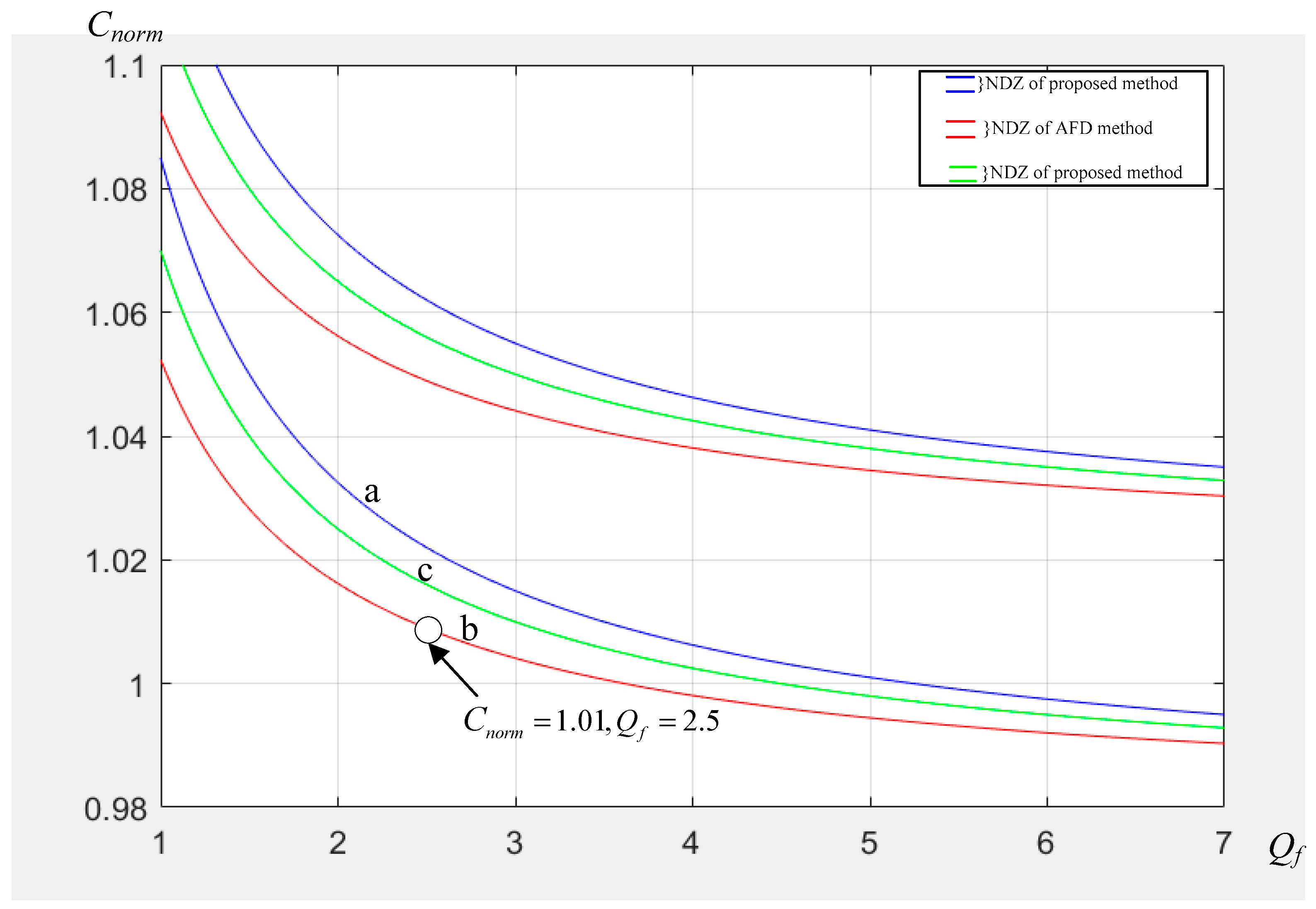
2.2. Parameters Analysis

The grid-connected DG system will satisfy the following equation:
P L o a d = P + Δ P Q L o a d = Q + Δ Q
where P L o a d , Q L o a d , Δ P , Δ Q , P , and Q represent the active and reactive power of the load, grid, and DG system, respectively.
The DG system supplies power to the load, and any excess power is absorbed by the grid or compensates for power shortages. Δ P , Δ Q describe the degree of matching between the DG system and the load after islanding occurs. The mismatched part is closely correlated with the NDZ. Generally, power mismatching occurs between the load and the DG system, while this mismatched part will be compensated for by the grid Δ P , Δ Q [23,24]. Islanding detection will fail when there is a power balance between the load and the DG system (that is Δ P = 0 , Δ Q = 0 ). The parameter(s) will be disturbed and reach a new value through the AFD techniques when the grid is disconnected. However, the parameter(s) may still be within the preset threshold for an extended period of time.
The relationship between the active and reactive power mismatch thresholds ( Δ P , Δ Q ) and the voltage/frequency thresholds can be expressed as follows [30]:
V V max 2 1 Δ P P V V min 2 1
Q f 1 f f min 2 Δ Q P Q f 1 f f max 2
where V max , V min , f m a x , f min are the voltage/frequency thresholds, respectively.
The power quality standards of China are applied in this paper [31]. The voltage threshold is +7% and −10% of the nominal voltage, respectively. The frequency threshold is 50 ± 0.5 Hz. Then, for Q f = 2.5 , there are the following:
13.37 % Δ P P 23.46 %
5.08 % Δ Q P 4.93 %
The mismatch will affect the parameter(s) (such as frequency, voltage, amplitude etc.) of the load once islanding happens, causing the islanding detection device to work. Active techniques intentionally create a mismatch to disrupt the balance between the load and the DG system, requiring larger Δ P / P and Δ Q / P to drive the parameter(s) beyond the threshold with a smaller NDZ. In the AFD method, the reactive power mismatch causes an imbalance between the load and the DG by injecting distortion into the current.
The active and reactive powers are described as Equations (9) and (10):
P = V I 1 cos ϕ 1
Q = V I 1 sin ϕ 1
where I 1 is the rms value and ϕ 1 is the phase angle of the fundamental waveform. From the Equations (9) and (10), Equation (11) can be derived:
Q P = tan ( ϕ 1 )
As can be seen, the phase angle of the fundamental waveform is in proportion to the reactive power generated by the distortion. The AFD method involves introducing a distortion into the current waveform in order to shift the fundamental current component by an angle of ϕ 1 . Obviously, the NDZ will decrease by increasing the injected reactive power to current waveform, while it leads to a higher THD at the same time.
It is expected that the techniques can detect islanding, while reducing the NDZ. In AFD method, the value of C f needs to be quite large to ensure the effective evaluation of the AFD method, which directly affects the THD. However, the THD is limited to THDmax < 5%. It is obvious that increasing the value of C f , which represents the perturbation intensity, will cause the THD to increase according to Equation (2).
Although the improved AFD method reduces the THD and NDZ to some extent, it still produces higher harmonics due to the disturbance method, or it compromises the detection speed for a smaller harmonic [9]. In view of this, an improved active method is proposed, and the basic perturbation way is changed. The proposed method not only has a higher detection speed and a smaller non-detection zone, but it can also effectively reduce the harmonic content and minimize the impact on power quality associated with the disturbance method.

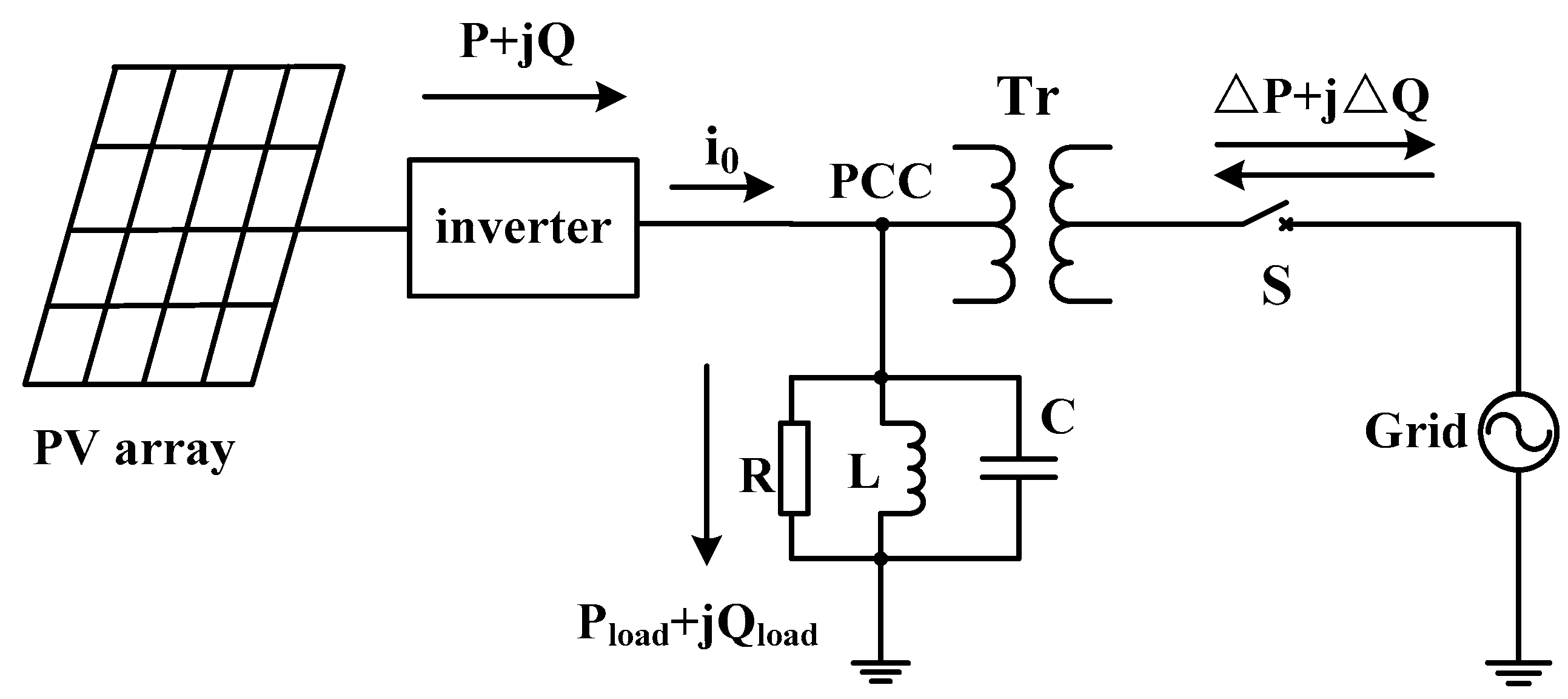
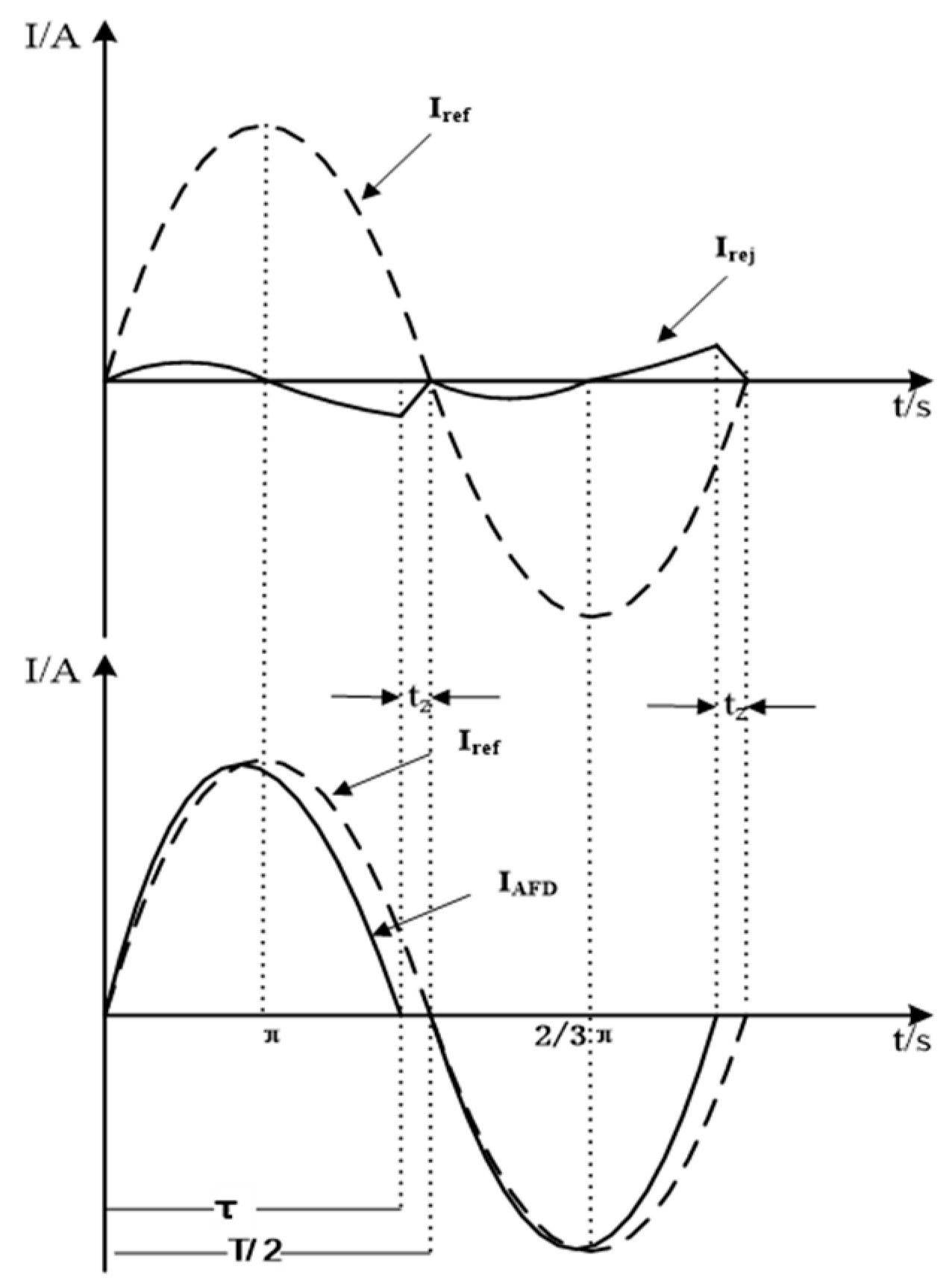
3. Principle of the Proposed Method

By injecting the reactive power every half cycle, the parameter(s) are gradually driven out of the threshold in the AFD method, but it causes a high level of harmonic distortion. Therefore, the aim of this paper is to present a novel method that utilizes an alternative perturbation technique, resulting in reduced total harmonic distortion (THD) and improved features.
In the proposed method, the injected harmonic currents differ from those used in AFD [22,25], resulting in different inverter output currents, as depicted in Figure 3.
Where, I r e f is the original reference current waveform, I o is the output current of the inverter, and I r e j is the injected harmonic current by the proposed method. T is the period of the reference current. During the time interval tz, the current equals to zero, which determines the magnitude of the perturbation depth.
The reference current waveform under the perturbation of the proposed method can be expressed as:
i ( t ) = I sin ( ω t + α ) k I                 0 ω t π α I sin ( ω t + α )                                 π α ω t 2 π α 0                                                                         2 π α ω t 2 π
where α is the phase difference between the current of the proposed method and the original reference current, and α = arcsin k , k is the perturbation factor. That is, the amplitude of the first half cycle is reduced by k on the basis of the offset.
In order to further decrease the THD, another perturbation method is proposed. The inverter output current is illustrated in Figure 4.
Where I o is the output current of the improved method.
Therefore, the current can be expressed as:
I = I sin ( ω t + α ) k I                   0 ω t π 2 α 0                                                                             π 2 α ω t π α I sin ( ω t + α )                                   π α ω t 2 π α 0                                                                             2 π α ω t 2 π
The chopping factor can be described as Equation (2).
The frequency of the proposed method will be drifted by the phase-shifting. This method changes the current frequency without distorting the current waveform. Since every half cycle of the current is sine wave, the harmonic of this method can be calculated approximately as:
T H D = 2 α 2 π 100 % = α π 100 %
It is calculated that THD = 2.4% using the proposed method when k = 0.075 , that is, C f = 0.0238 . The injected reactive power is calculated as follows:
Figure 4. Improved current waveform.
Processes 11 01838 g004
The Equation (13) can be expanded in the Fourier series:
F ( t ) = a o + n = 1 ( a n cos n ω t + b n sin n ω t )
a 1 = I ( k 2 k 2 π )
b 1 = I ( 1 2 k π )
Equation (11) can be rewritten:
Q P = π k 2 k 2 π 2 k 100 %
when k = 0.075 , the reactive power of the proposed improved method can be obtained:
Q P = 7.5 %
According to reference [21], Equation (19) satisfies conventional AFD method law:
T H D = Q P
In that way, when Q/P of both methods is set as 7.5%, according to Equations (11) and (20), the THD injected into the grid with the proposed method is 2.4%, while the THD with conventional AFD method is 7.5%. In addition, the proposed method reduces the harmonic by 68% when compared to the conventional AFD. Likewise, when both of the THD are 2.4%, the proposed method injects reactive power 7.5% to the grid, while the conventional AFD only injects 2.4%. Therefore, with the same THD as the conventional AFD, the proposed method will achieve a significantly higher Q/P ratio. This may result in larger parameter fluctuations, which may accelerate the speed of islanding detection.
Once the grid is disconnected, the frequency variation of PV with RLC load satisfies the follow equation:
arg [ R 1 + ( j ω L ) 1 + ( j ω C ) ] 1 = tan 1 ( π k 2 k 2 π 2 k )
According to Equations (3) and (21), the analysis of the non-detection zone is given as Figure 5. Under the proposed method, the non-detection zone with k = 0.09 , k = 0.15 are a and c, respectively; b is the distribution of the non-detection zone with C f = 0.046 of the conventional AFD method.
According to IEEE std. 929-2000 [32], that is C n o r m = 1.01 , Q f = 2.5 , c is the NDZ of the proposed method with k = 0.15 and has a THD of 4.9%; b is the NDZ of the conventional AFD method with C f = 0.046 . It is evident that the conventional AFD may fail at this point, which is located on the boundary of NDZ. Nevertheless, the proposed method can successfully operate beyond the NDZ boundary. This is a noteworthy advantage as it leads to a decrease in the overall size of the NDZ by increasing the value k of the proposed method, which is depicted in Figure 5.
In order to illustrate the relationship between C f and THD, the THD and islanding detection time can be measured in simulation software of Matlab/Simulink under different C f . Several groups of data obtained from the simulation can then be mapped, as shown in Figure 6 and Figure 7.
From Figure 6 and Figure 7, it can be seen that as the C f gets increased, the detection speed accelerates, and the THD level rises. The faster the detection speed, the easier it becomes to detect, and the smaller the NDZ is. Conversely, the slower the detection speed, the more difficult it is to detect, and the greater the size of the NDZ. In other words, to reduce the NDZ, the value of C f must be increased. According to Figure 7, the proposed improved method in this paper has a faster detection speed and lower THD compared to the AFD method. In other words, the proposed method not only has a faster detection speed and smaller NDZ, but it also significantly reduces THD compared to the AFD method. For instance, as depicted in Figure 7 at points a and b, the detection time is similar for both methods, but the THD of the AFD method is as high as 4.18%, whereas the proposed method has a significantly lower THD of only 1.76%. Under identical conditions, the improved method shows lower harmonics and faster detection speed. In summary, the proposed improved active island detection method has better detection performance, faster detection speed, lower harmonics, smaller NDZ, and higher practical application value compared to the AFD method.

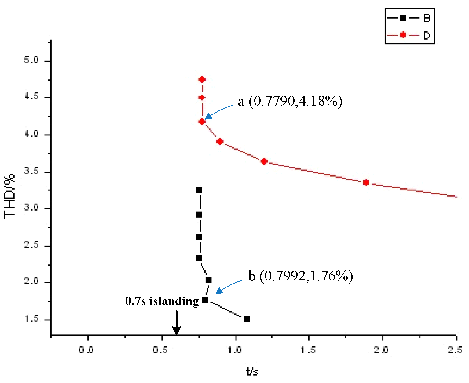
4. Results and Discussion

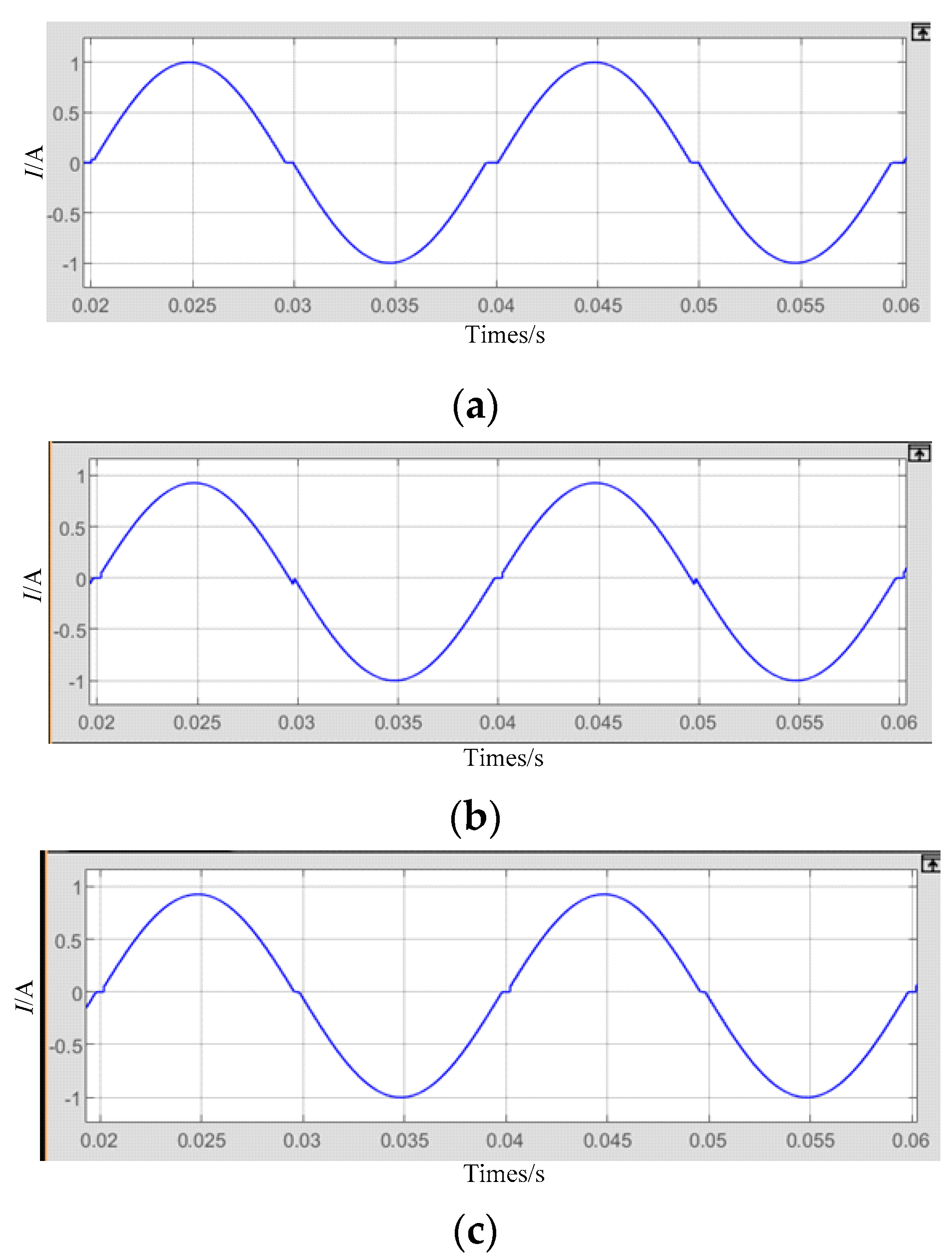
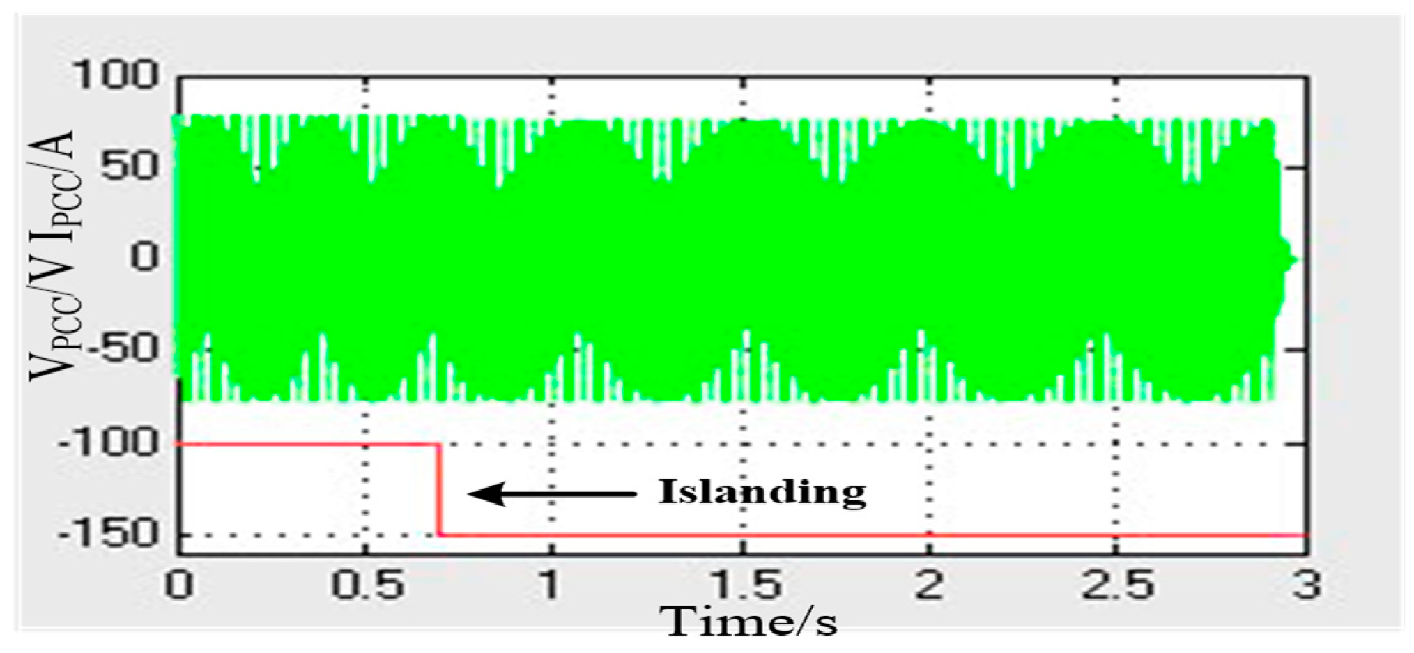
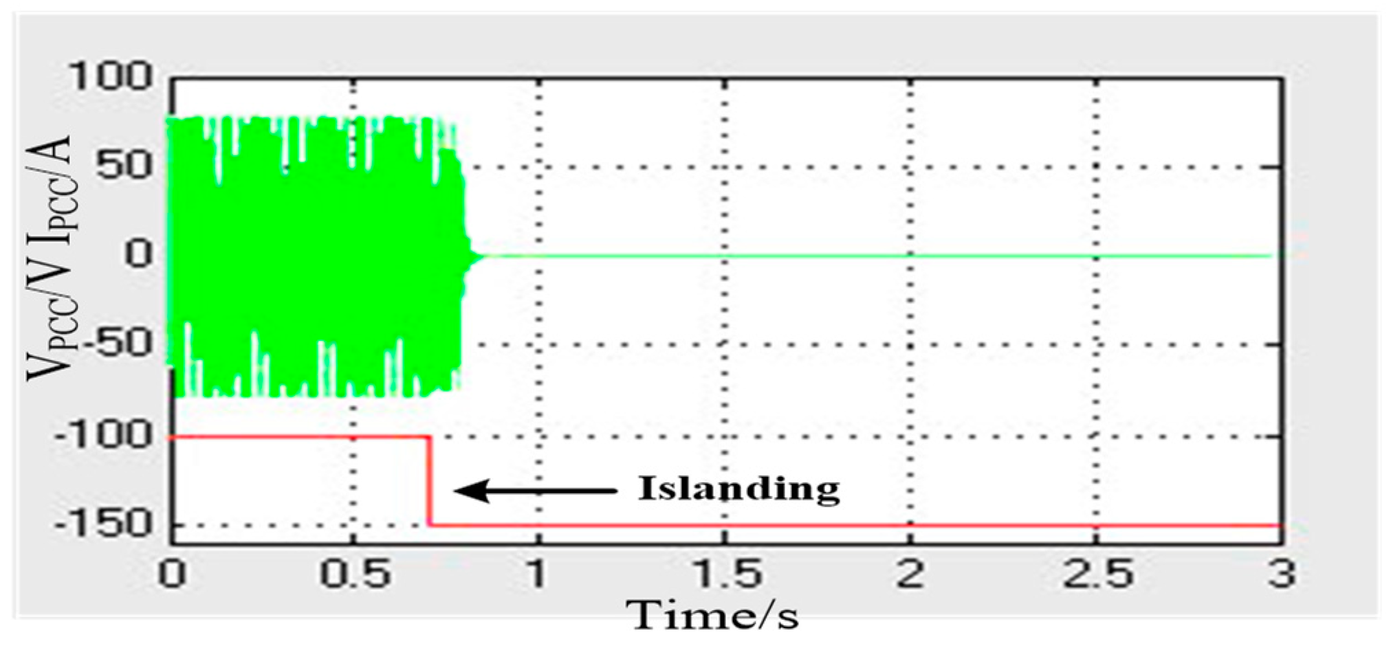
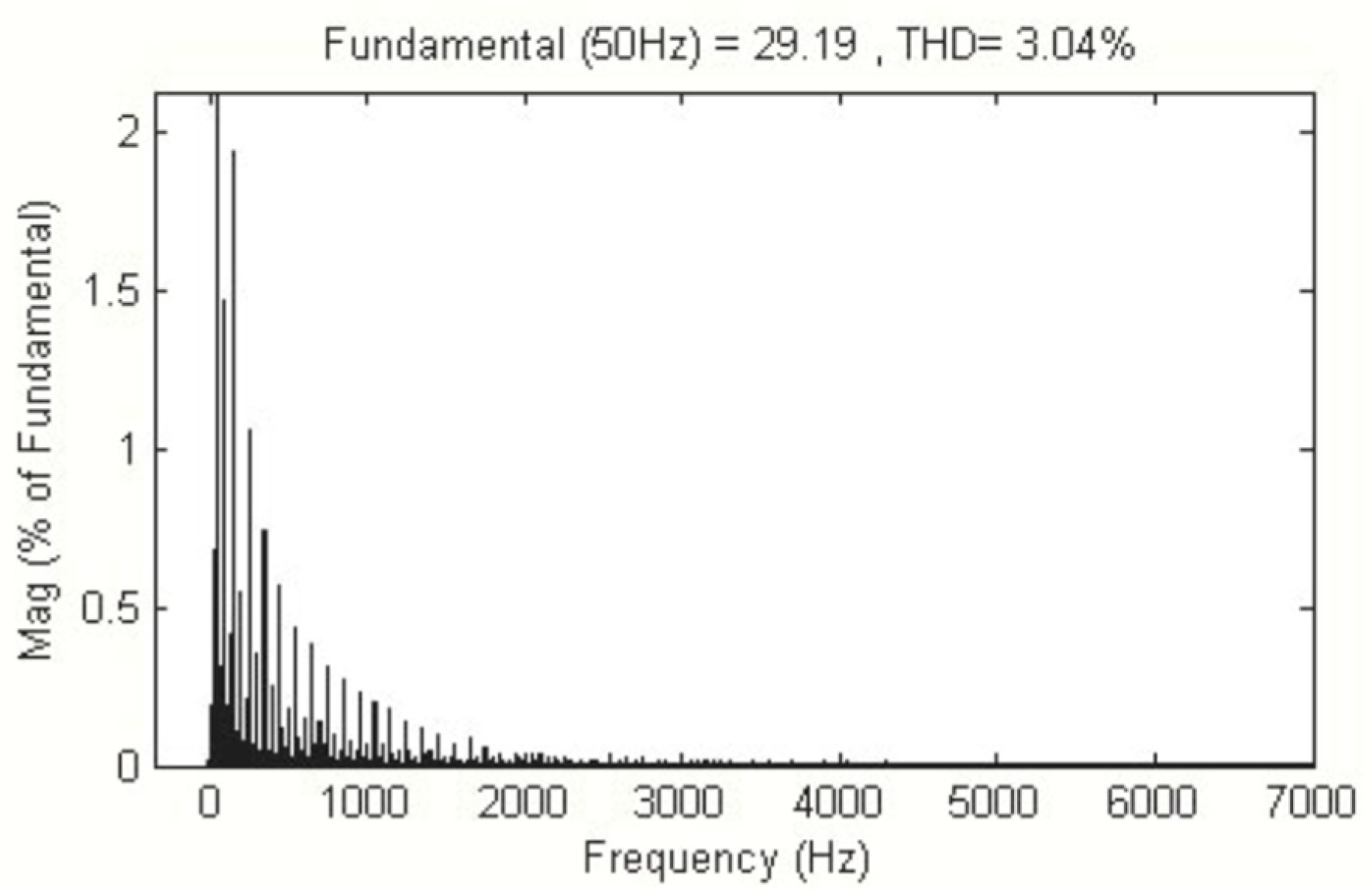
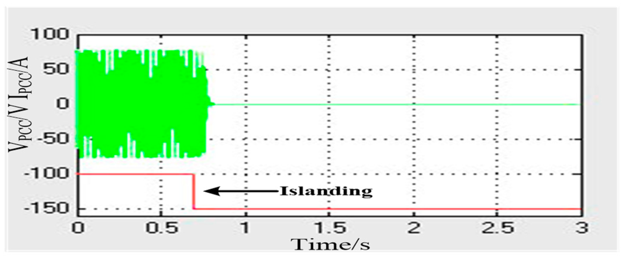
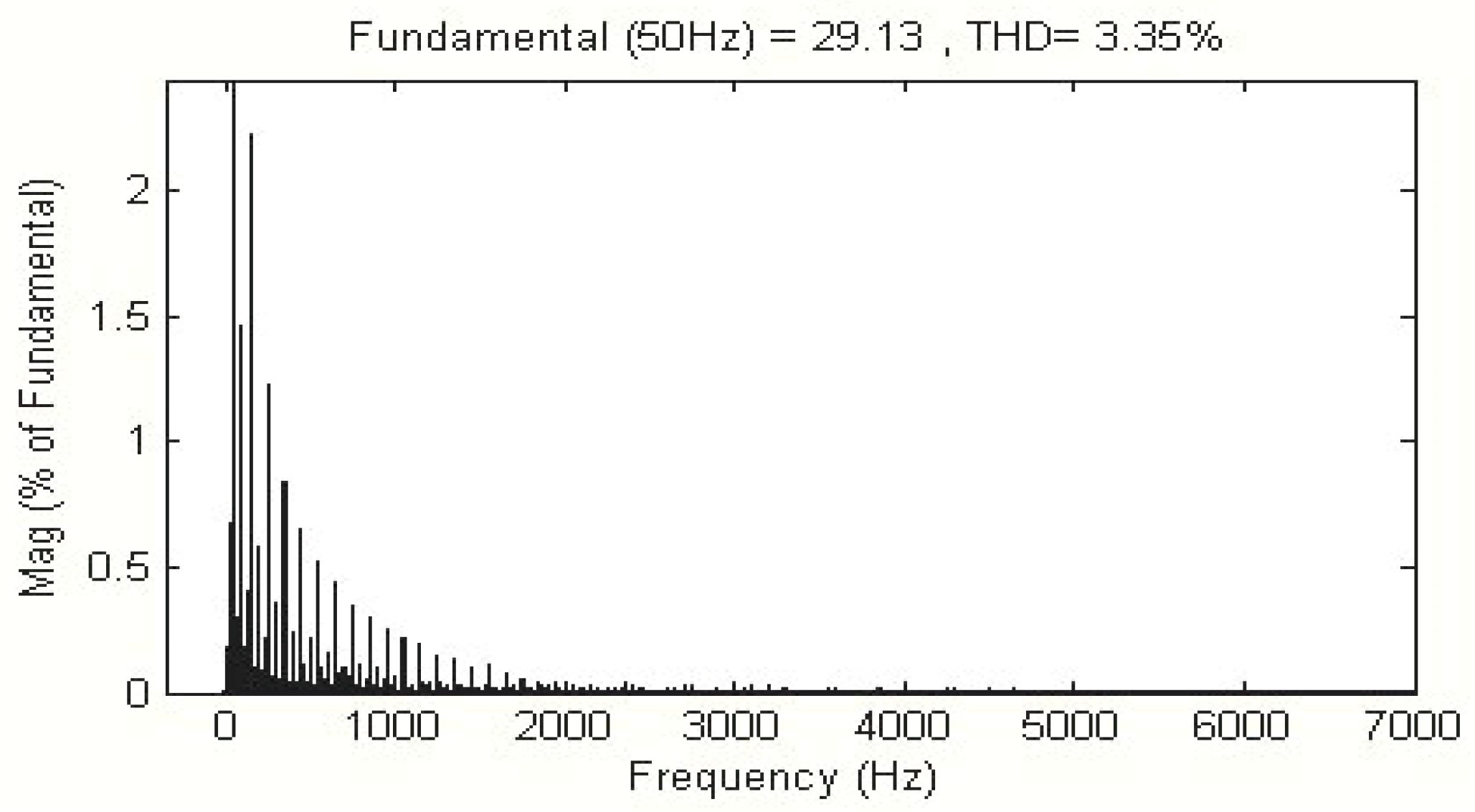
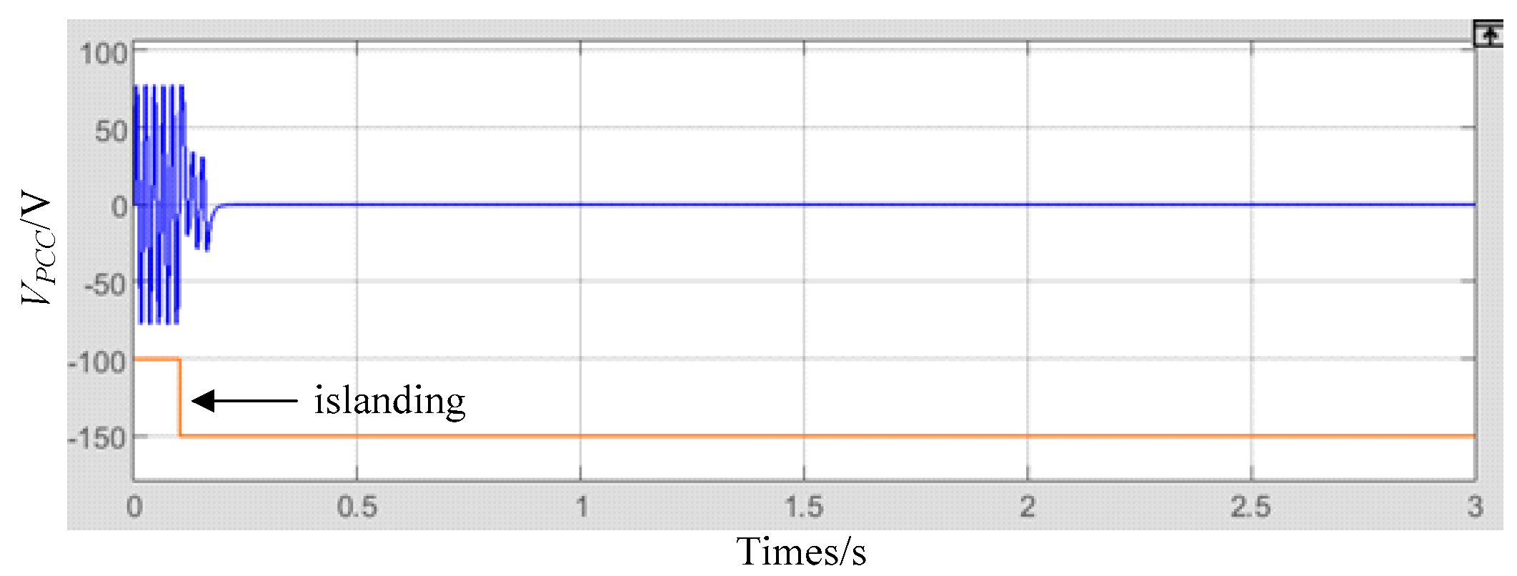
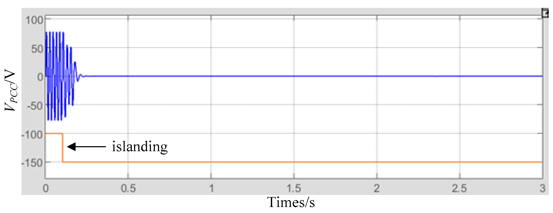
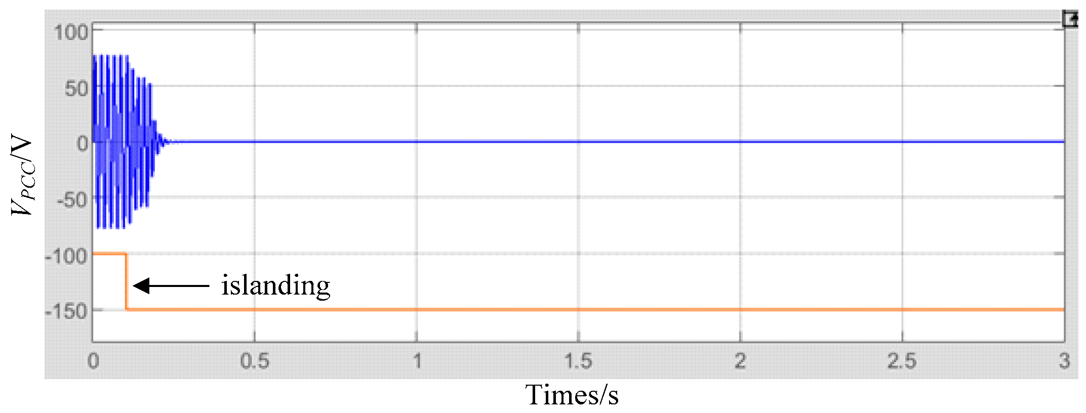
4.1. Simulation Results

According to the power quality standards of China [31], a detailed simulation has been conducted in the 220 V system. The voltage threshold is +7%, −10% of the nominal voltage, ensuring the stability and reliability of the system. The frequency threshold is ±0.5 Hz, a detection time of no more than 2 s has been requested, and the THD should be under 5%.
The RLC load will be resonant when ω C = 1 / ω L , so the quality factor should be Q f = R / ω o L .
Simulation software of Matlab/Simulink is adopted to make simulation analyses. The parameters are listed in Table 1.
The injected current waveforms are illustrated in Figure 8. Under conventional AFD, the proposed method and the proposed improved methods specifically when α = 0.08 (that is can be observed in Figure 8a–c, respectively).
This paper puts forward a novel improved method, and the results of detection are nearly identical. Based on the analysis in Section 3, it can be seen that the improved method is straightforward to implement and has a relatively low harmonic injection into the power grid, making it more practically significant. Hence, this paper adopts the improved method to conduct simulations and experiments and compare it with the conventional AFD method.
When α = 0.08 ( t z = 0.255   m s ), the detection results and harmonic analysis are illustrated in Figure 9, Figure 10, Figure 11 and Figure 12, respectively.
It can be concluded from Figure 9, Figure 10, Figure 11 and Figure 12 that it takes the conventional AFD method 2.2 s to detect the islanding. However, the proposed method is able to detect islanding in just 0.1 s when α = 0.08 ( t z = 0.255   m s ). Additionally, it also can be observed that the THD of conventional AFD is 3.04%, which is higher than the THD of the proposed method, measured at only 2.62%.
When α = 0.09 ( t z = 0.286   m s ), the detecting results and the harmonic analysis using the conventional AFD and the proposed method are illustrated in Figure 13, Figure 14, Figure 15 and Figure 16, respectively.
It can be concluded from Figure 13, Figure 14, Figure 15 and Figure 16 that it takes the conventional AFD method 1.15 s to detect the islanding. However, it is only 0.1 s for the proposed method when α = 0.09 ( t z = 0.286   m s ). It can be observed that the THD of conventional AFD is 3.35%, which is higher than the THD of the proposed method, which measured only 2.91%.
Based on the detection results of two groups, the proposed method exhibits superior detection capabilities compared to the conventional AFD method under the same conditions, while maintaining a lower THD. As α increases, the detection time will decrease while the THD will increase.
To further confirm the effectiveness of the proposed islanding detection technique, various simulations were conducted under different islanding scenarios and only set the frequency threshold, which is ±0.5 Hz. Specifically, the simulations were conducted by changing the load resistance and load inductance, which represent the scenarios of active power mismatch and reactive power mismatch, respectively. The simulation results are presented in Figure 17, Figure 18, Figure 19, Figure 20, Figure 21 and Figure 22.
The simulation results for scenarios involving only changes in load resistance, i.e., active power mismatch, are presented in Figure 17, Figure 18 and Figure 19. Based on these figures, it can be observed that the voltage changes to a new level when the grid disconnects, and the detection time is 0.01 s, 1.18 s, and 0.2 s, respectively, for Qf = 0, 1, 4, depending on the level of active power imbalance. Since this simulation only detects frequency, it takes longer to detect islanding when the active power mismatch is low, such as when Qf = 1. However, in actual GCPVS, passive detection is combined with this method for island detection. When the voltage drops below the preset value, the island is immediately detected, and a long detection time is not necessary.
The simulation results for scenarios involving only changes in load inductance, i.e., reactive power mismatch, are presented in Figure 20, Figure 21 and Figure 22. Based on these figures, it can be observed that the frequency changes to a new level when the grid disconnects, and the detection time is 0.08 s, 0.11 s, and 0.13 s, respectively, for Qf = 0, 1, 4, depending on the level of reactive power imbalance. Similarly, since this simulation only detects frequency, even when the reactive power mismatch is low, the required detection time is not long.

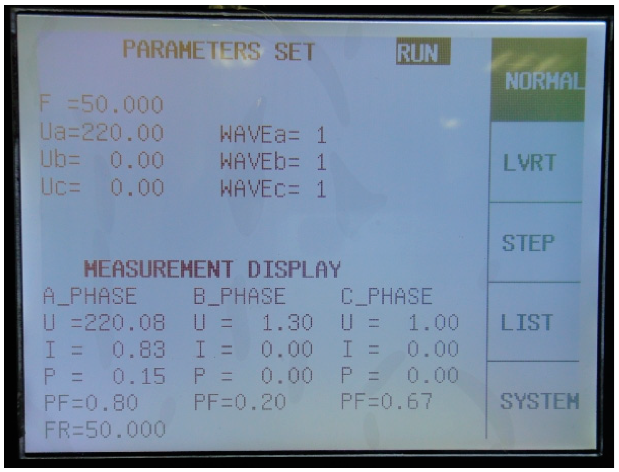
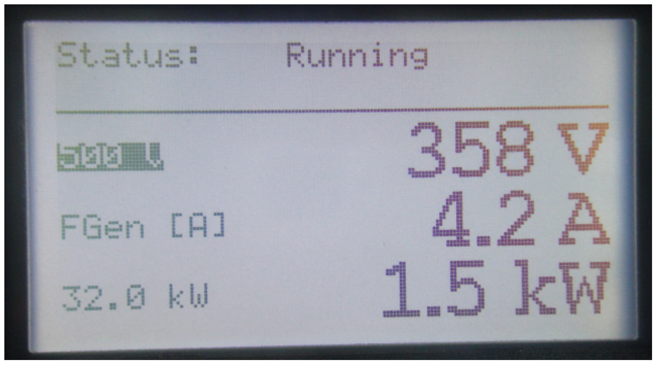
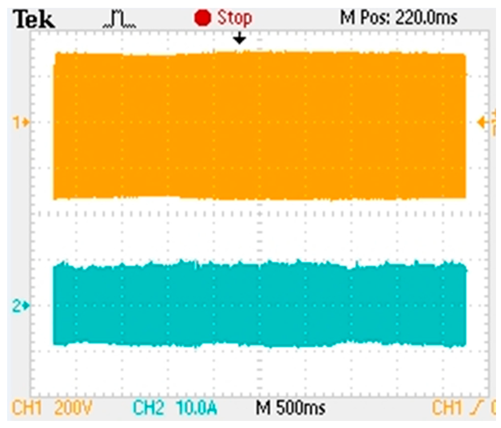
4.2. Experimental Results

To verify the proposed system, a prototype was constructed, and experimental testing was conducted. A solar panel simulator rated at 1.5 k W and 360 V DC voltage was used to simulate a DC source, with a reactive power of approximately 0.27 kW. The grid simulator was utilized to simulate a power grid, with an adjustable RLC parallel load.
Once the system was operating stably, as shown in Figure 23, the state parameters were set to 0 for the b and c phase voltages, while the a phase voltage was set to 220 V with a frequency of 50 Hz. The inverter power was set to 1.5 kW, and the maximum power point voltage of the DC measurement was set to 360 V. The system parameters after achieving stability are shown in Figure 24. Once the system was stable, island protection testing was conducted.
After the inverter is connected to the grid, the system operates normally. From top to bottom is the voltage and current of the system measured by a digital oscilloscope, as shown in Figure 25. When the power grid operates normally, due to the clamping effect of the grid, the inverter and grid voltage remain synchronized.
After the inverter is connected to the grid, the power of the load is first adjusted to match the output power of the inverter with the required power of the load, and the RLC load resonates. Once the load resonance has occurred, the inverter can provide the required power to the load, and the power grid no longer needs to supply voltage. Consequently, the current at the grid end is very small, typically around 1% of the normal value, as shown in Figure 26. Figure 27 shows the system voltage Urms1 and current Ifnd1, active P1 and reactive Q1 parameter values measured by the power analyzer after resonance. The system voltage stabilizes at around 220 V with slight fluctuations, and at this time, the grid terminal current is 1% of the fundamental frequency current. As shown in Figure 27, the active and reactive powers of grid are also very small. If anti-islanding measures are not taken after load resonance when the grid is disconnected, the islanding state can be maintained during operation.
The voltage and current waveforms were measured using a power analyzer and are depicted in Figure 28 and Figure 29. The top-down waveforms show the system voltage waveform and the grid current waveform obtained using the conventional AFD method and the proposed method, respectively. The RMS voltage and current were measured at 220 V and 6.5 A, respectively, with a frequency of 50 Hz.
The experimental results showed that the distortion of the current generated by the proposed method was smaller than that of the AFD method. This finding is significant as it demonstrates the effectiveness of the proposed method in reducing distortion during the current generation process.

5. Conclusions

Islanding in a grid-connected photovoltaic system has the potential to cause significant damage and threaten the safety of both electrical repair personnel and users. Therefore, it is imperative to implement measures to prevent or detect islanding in grid- connected photovoltaic systems. The most common method combines active and passive methods, with the active frequency drift (AFD) method being an effective active method due to its smaller non-detection zone (NDZ) and lower cost. However, the AFD method can introduce higher harmonic distortion to the system and requires careful consideration of the detecting speed and NDZ. Although an improved AFD method has been developed to optimize the NDZ, it still exhibits high harmonic distortion. To address this limitation, an innovative method has been proposed to effectively decrease harmonic distortion during AFD islanding detection. The proposed method utilizes different injecting harmonic currents compared to AFD. After Fourier analysis and laboratory experiments, it was found that the harmonic distortion of the proposed method is reduced by 68% compared to conventional AFD, while the chopping factor is larger than that of conventional AFD. These results demonstrate that the proposed method effectively decreases harmonic distortion without compromising detecting speed or increasing the non-detection zone. Therefore, the proposed method represents a significant advancement in the quest to enhance the safety and efficiency of islanding detection in photovoltaic systems.

Author Contributions

Conceptualization, S.Z. and R.Z.; Formal analysis, Z.H.; Investigation, L.W.; Methodology, S.Z., R.Z. and X.D.; Resources, L.W.; Software, L.W. and S.D.; Validation, S.Z., R.Z. and J.Z.; Writing—original draft, R.Z. and W.Y.; Writing—review and editing, S.Z. and P.W.; S.Z. and L.W. are co-first authors. All authors have read and agreed to the published version of the manuscript.

Funding

This research was funded by the S&T Program of Hebei (22352201D); Open Project of Provincial Collaborative Innovation Center of Industrial Energy-saving and Power Quality Control, Anhui Province (KFKT201504); Science Foundation of Hebei Normal University (L2023J03).

Institutional Review Board Statement

Not applicable.

Informed Consent Statement

Not applicable.

Data Availability Statement

Not applicable.

Conflicts of Interest

The authors declare no conflict of interest.

References

  1. Fathi-Jowzdani, A.H.; Sadeghkhani, I.; Mehrizi-Sani, A. Islanding detection for DC microgrids based on episode of care severity index. IEEE Trans. Smart Grid 2022, 13, 954–961. [Google Scholar] [CrossRef]
  2. Voglitsis, D.; Papanikolaou, N.P.; Kyritsis, A.C. Active cross-correlation anti-islanding scheme for PV module-integrated converters in the prospect of high penetration levels and weak grid conditions. IEEE Trans. Power Electron. 2019, 34, 2258–2274. [Google Scholar] [CrossRef]
  3. Masan, J.C.; Zheng, H.B.; Zhang, C.H. An islanding detection and prevention method based on path query of distribution network topology graph. IEEE Trans. Sustain. Energy 2022, 13, 81–90. [Google Scholar]
  4. Altaf, M.W.; Arif, M.T.; Oo, A. Effective ROCOF-based islanding detection technique for different types of microgrid. IEEE Trans. Ind. Appl. 2022, 58, 1809–1821. [Google Scholar] [CrossRef]
  5. Choudhury, B.K.; Jena, P. Superimposed impedance-based passive islanding detection scheme for DC microgrid. IEEE J. Emerg. Sel. Top. Power Electron. 2022, 10, 469–483. [Google Scholar] [CrossRef]
  6. Kumar, P.; Kumar, V.; Tyagi, B. A novel islanding detection technique based on event index value for reconfigurable microgrid. IEEE Trans. Ind. Appl. 2021, 57, 3451–3462. [Google Scholar] [CrossRef]
  7. Yazdani, S.; Ferdowsi, M.; Shamsi, P. Internal model based smooth transition of a three-phase inverter between islanded and grid-connected modes. IEEE Trans. Energy Convers. 2020, 35, 405–415. [Google Scholar] [CrossRef]
  8. Ganivada, P.K.; Jena, P. Active slip frequency based islanding detection technique for grid-tied inverters. IEEE Trans. Ind. Inf. 2020, 16, 4615–4626. [Google Scholar] [CrossRef]
  9. Yafaoui, A.; Wu, B.; Kouro, S. Improved active frequency drift anti-islanding detection method for grid connected photovoltaic systems. IEEE Trans. Power Electron. 2012, 27, 2367–2375. [Google Scholar] [CrossRef]
  10. Xu, W.; Zhang, G.; Li, C.; Wang, W.; Wang, G.; Kliber, J. A power line signaling based technique for anti-islanding protection of distributed generators–Part I: Scheme and analysis. IEEE Trans. Power Deliv. 2007, 22, 1758–1766. [Google Scholar] [CrossRef]
  11. Davidson, E.M.; Mcarthur, S.D.J.; Mcdonald, J.R.; Cumming, T.; Watt, I. Applying multi-agent system technology in practice: Automated management and analysis of SCADA and digital fault recorder data. IEEE Trans. Power Syst. 2006, 21, 559–567. [Google Scholar] [CrossRef]
  12. Bratton, R.E. Transfer-trip relaying over a digitally multiplexed fiber optic link. IEEE Trans. Power Appar. Syst. 1984, 103, 403–406. [Google Scholar] [CrossRef]
  13. Mlakic, D.; Baghaee, H.R.; Nikolovski, S. Gibbs phenomenon-based hybrid islanding detection strategy for VSC-based microgrids using frequency shift, THDU, and RMSU. IEEE Trans. Smart Grid 2019, 10, 5479–5491. [Google Scholar] [CrossRef]
  14. Lopes, L.A.C.; Huili, S. Performance assessment of active frequency drifting islanding detection methods. IEEE Trans. Energy Convers. 2006, 21, 171–180. [Google Scholar] [CrossRef]
  15. Singam, B.; Hui, L.Y. Assessing SMS and PJD schemes of anti-islanding with varying quality factor. In Proceedings of the IEEE Power Energy Conference, Putra Jaya, Malaysia, 28–29 November 2006; pp. 196–201. [Google Scholar]
  16. Bertling, F.; Soter, S. A novel converter integrable impedance measuring method for islanding detection in grids with widespread use of decentral generation. In Proceedings of the International Symposium on Power Electronics, Electrical Drives, Automation and Motion, Taormina, Italy, 23–26 May 2006; pp. 503–507. [Google Scholar]
  17. Seyedi, M.; Taher, S.A.; Ganji, B. A hybrid islanding detection technique for inverter-based distributed generator units. IEEE Trans. Electr. Energy Syst. 2019, 29, e12113. [Google Scholar] [CrossRef]
  18. Ropp, M.E.; Begovic, M.; Rohatgi, A. Analysis and performance assessment of the active frequency drift method of islanding prevention. IEEE Trans. Energy Convers. 1999, 14, 810–816. [Google Scholar] [CrossRef]
  19. Smith, G.A.; Onios, P.A.; Infield, D.G. Predicting islanding operation of grid connected PV inverters. IEEE Power Appl. 2000, 147, 1–6. [Google Scholar] [CrossRef]
  20. Hung, G.K.; Chang, C.C.; Chen, C.L. Automatic phase-shift method for islanding detection of grid-connected photovoltaic inverters. IEEE Trans. Energy Convers. 2003, 18, 169–173. [Google Scholar] [CrossRef]
  21. Jung, Y.; Choi, J.; Yu, B.; Yu, L.; So, J. A novel active frequency drift method of islanding prevention for the grid-connected photovoltaic inverter. In Proceedings of the IEEE 36th Conference on Power Electronics Specialists, Recife, Brazil, 16 June 2005; pp. 1915–1921. [Google Scholar]
  22. Bakhshi-Jafarabadi, R.; Sadeh, J.; Popov, M. Maximum Power Point Tracking Injection Method for Islanding Detection of Grid-Connected Photovoltaic Systems in Microgrid. IEEE Trans. Power Deliv. 2021, 36, 168–179. [Google Scholar] [CrossRef]
  23. Barkat, F.; Cheknane, A.; Banu, I.V. Hybrid islanding detection technique for single-phase grid-connected photovoltaic multi-inverter systems. IET Renew. Power Gener. 2020, 14, 3864–3880. [Google Scholar] [CrossRef]
  24. Reddy, V.R.; Sreeraj, E.S. A hybrid islanding detection method for one cycle controlled PV inverter system. IEEE J. Emerg. Sel. Top. Ind. Electron. 2021, 3, 777–787. [Google Scholar] [CrossRef]
  25. Bakhshi-Jafarabadi, R.; Sadeh, J.; Rakhshani, E. Review on islanding detection methods for grid-connected photovoltaic systems, existing limitations and future insights. IET Renew. Power Gener. 2022, 16, 3406–3421. [Google Scholar] [CrossRef]
  26. Ropp, M.E.; Begovic, M.; Rohatgi, A. Prevention of islanding in grid connected photovoltaic systems. Progr. Photovolt. Res. Appl. 1999, 7, 39–59. [Google Scholar] [CrossRef]
  27. Liu, F.; Kang, Y.; Duan, S. Analysis and optimization of active frequency drift islanding detection method. In Proceedings of the 22nd Annual IEEE Applied Power Electronics Conference (APEC), Anaheim, CA, USA, 25 February–1 March 2007; pp. 1379–1384. [Google Scholar]
  28. Zhu, X.; Shen, G.; Xu, D. Evaluation of AFD islanding detection methods based on NDZs described in power mismatch space. In Proceedings of the IEEE Energy Conversion Congress and Exposition (ECCE), San Jose, CA, USA, 20–24 September 2009; pp. 2733–2739. [Google Scholar]
  29. John, V.; Ye, Z.; Kolwalkar, A. Investigation of anti-islanding protection of power converter based distributed generators using frequency domain analysis. IEEE Trans. Power Electron. 2004, 19, 1177–1183. [Google Scholar] [CrossRef]
  30. Ye, Z.; Kolwalkar, A.; Zhang, Y.; Du, P.; Walling, R. Evaluation of anti islanding schemes based on non detection zone concept. IEEE Trans. Power Electron. 2004, 19, 1171–1176. [Google Scholar] [CrossRef]
  31. GB/T 19939-2005; General Administration of Quality Supervision, Inspection and Quarantine of the People’s Republic of China, China National Standardization Administration. Technical Requirements for Crid Connection of PV System. Standards Publishing House: Beijing, China, 2005.
  32. IEEE Std. 929-2000; IEEE Standards Coordinating Committee 21 on Fuel Cells, Photovoltaics, Dispersed Generation, and Energy Storage. IEEE Recommended Practice for Utility interface of Photovoltaic (PV) Systems. The Institute of Electrical and Electronics Engineers: New York, NY, USA, 2000.
Figure 1. Schematic for islanding event description.
Processes 11 01838 g001
Figure 2. Current waveform of AFD.
Processes 11 01838 g002
Figure 3. Proposed current waveform.
Processes 11 01838 g003
Figure 5. NDZ for different C n o r m . (The non-detection zone with k = 0.09 , k = 0.15 are a and c, respectively; b is the distribution of the non-detection zone with C f = 0.046 of the conventional AFD method).
Processes 11 01838 g005
Figure 6. Relationship between C f and THD (B—proposed improved method; C—conventional AFD method).
Processes 11 01838 g006
Figure 7. Relationship curve between THD and detection time (B—proposed method; D—conventional AFD method).
Processes 11 01838 g007
Figure 8. Simulation current waveform of conventional AFD and the proposed method. (a) is current waveform of conventional AFD, (b) is current waveform of the proposed method and (c) is current waveform of the proposed improved methods when α = 0.08 .
Processes 11 01838 g008
Figure 9. Result of conventional AFD method.
Processes 11 01838 g009
Figure 10. Result of the proposed method.
Processes 11 01838 g010
Figure 11. THD of conventional AFD.
Processes 11 01838 g011
Figure 12. THD of the proposed method.
Processes 11 01838 g012
Figure 13. Result of conventional AFD.
Processes 11 01838 g013
Figure 14. Result of the proposed method.
Processes 11 01838 g014
Figure 15. THD of conventional AFD.
Processes 11 01838 g015
Figure 16. THD of the proposed method.
Processes 11 01838 g016
Figure 17. Result with Qf = 0.
Processes 11 01838 g017
Figure 18. Result with Qf = 1.
Processes 11 01838 g018
Figure 19. Result with Qf = 4.
Processes 11 01838 g019
Figure 20. Result with Qf = 0.
Processes 11 01838 g020
Figure 21. Result with Qf = 1.
Processes 11 01838 g021
Figure 22. Result with Qf = 4.
Processes 11 01838 g022
Figure 23. Grid parameters.
Processes 11 01838 g023
Figure 24. State parameters of the inverter after stabilization.
Processes 11 01838 g024
Figure 25. Voltage and current during normal operation of the power grid.
Processes 11 01838 g025
Figure 26. Voltage and current of the system after load resonance.
Processes 11 01838 g026
Figure 27. Parameters after load resonance.
Processes 11 01838 g027
Figure 28. Waveform of the conventional AFD method.
Processes 11 01838 g028
Figure 29. Waveform of the proposed method.
Processes 11 01838 g029
Table 1. Simulation parameters.
Components Parameters
active power4.585 kW
reactive power47 Var
quality factor2
resonant frequency50.2 Hz
L (inductance)16.724 mH
C (capacitance)601.026 μF
R (load)10.55 Ω
Grid220 V, 50 Hz
InverterDC/AC converter topology, 1.5 kW
current and voltage controllers for inverterPID
PV arraymaximum power point voltage, 360 V
Disclaimer/Publisher’s Note: The statements, opinions and data contained in all publications are solely those of the individual author(s) and contributor(s) and not of MDPI and/or the editor(s). MDPI and/or the editor(s) disclaim responsibility for any injury to people or property resulting from any ideas, methods, instructions or products referred to in the content.

