1. Introduction
The anchor bolt is widely used in support engineering because of its advantages of speedy installation and applicability to most types of rocks [
1]. The anchor grouting methods for bolts include end-grouted, lengthen-grouted and full-grouted. In order to improve the support effect and reduce the deformation of tunnel-surrounding rock, most end-grouted bolts and length-grouted bolts will be preloaded, while the full-grouted bolts are usually not applied due to the complex process and difficult operation involved [
2,
3,
4]. With the development and implementation of underground engineering, the characteristics of high ground stress, extremely broken surrounding rock and extra-large sections are becoming increasingly common, and the support of surrounding rock is also facing more severe challenges [
5,
6,
7]. The full-grouted prestressed bolt has the advantages of end-grouted and lengthen-grouted prestressed bolts, such as a large prestressed diffusion range and sensitivity to surrounding rock deformation, which can effectively prevent the deformation of surrounding rock, so it is widely used in various supporting projects [
8,
9,
10,
11]. For most coal-mine roadways, the surrounding rock is mainly composed of layered sedimentary rock [
12]. The uncoordinated deformation of rock mass will lead to the generation of bed separation, and the expansion of separation will produce additional pull-out loads on the bolts. In this case, the influence of separation on the mechanical properties of the full-grouted prestressed bolts will become the key to support design [
13].
There are many methods for studying the mechanical properties of full-grouted bolts under surrounding rock deformation, such as theoretical analysis, laboratory experiments, on-site monitoring and numerical simulation. Ding Xiao established an elastic–plastic mechanical model and concluded that the whole stress process of bolts under the action of bed separation can be divided into five stages [
14]. Some scholars have systematically studied the distribution characteristics and influencing factors of the axial force and interfacial shear stress of full-grouted bolts in surrounding rock under the linear interface model by using the load-transfer method [
15,
16,
17,
18]. Liu Guoqing and Ma adopted the two-broken-line interface model and the three-broken-line interface model to consider the influence of interface residual shear strength and post-peak softening characteristics and analyzed the stress characteristics of full-grouted bolts in surrounding rock [
19,
20]. Shang Fulu derived a theoretical model for full-grouted prestressed bolts under the action of bed separation and analyzed the influence of design parameters on the mechanical properties of anchor rods by establishing a numerical model [
21]. Ding Xiao designed a layer-separation test to study the stress characteristics of vertical bolts and inclined bolts under the action of layer separation [
22]. Of course, in recent years, many scholars around the world have conducted research work on full-grouted anchor bolts [
23,
24,
25,
26].
In summary, there have been many studies on the mechanical properties of full-grouted bolts, but there are still some problems. For example, the existing research rarely considers the prestress of the bolts, that is, the research objects are mainly the full-grouted bolts rather than prestressed full-grouted bolts. Furthermore, research on the mechanical properties of full-grouted prestressed bolts under various separation conditions is even more lacking. In order to systematically study the influence of different bed-separation parameters on the mechanical characteristics of full-length prestressed anchor bolts under elastic state, a theoretical model of the full-grouted prestressed bolt based on the superposition principle will be demonstrated and a verified numerical-analysis model will be established in this paper. Further, numerical simulation tests were carried out for three working conditions, the bed-separation value, the bed-separation number and the bed-separation location, to reveal the variation in the bolt axial force and anchorage–interface shear stress. At the same time, the contribution and sensitivity of different parameters were studied by range analysis and variance analysis.
2. Theoretical Model of Bolts under the Action of the Separation Layer
2.1. Structure of Full-Grouted Prestressed Bolt
In an ideal state, the full-grouted prestressed bolt should be implemented in two steps [
13,
27].
Figure 1 shows the basic structure of the full-grouted prestressed bolt’s anchorage under the bed separation
b. The whole length (
L) of the bolt is bonded to the hole wall of the bolt, which can be divided into the initial bonding section
Ld and the secondary bonding section
La according to the sequence of anchor–grout condensation. The initial bonding section is used to apply prestress
F to the bolt, and the secondary bonding section realizes the full-length bonding of the bolt after the prestress is applied.
2.2. Theoretical Model of the Bolt
According to the implementation process of the full-grouted prestressed bolt, its state can be divided into three stages, as shown in
Figure 2.
Stage 1: Applying prestressing force, as shown in
Figure 2a. At this stage, the bolt is prestressed through the initial bonding section, and its structural characteristics are completely consistent with the end-grouted bolt. In engineering, the prestress can be applied by using the fast-anchoring agent in the initial bonding section and the slow-anchoring agent in the secondary bonding section.
Stage 2: Supplementary grouting, as shown in
Figure 2b. At this stage, the deformation of the rock and the shear stress at the anchoring interface on the secondary bonding section are relatively small, so the stress state of the bolt is almost the same as that of stage 1.
Stage 3: Generation and expansion of bed separation, as shown in
Figure 2c. Starting from this stage, the bolt begins to operate normally. At this point, the deformation of the rock gradually develops, and the axial force and interfacial shear stress of the anchor rod at the crack reach their peak value. As the detachment deformation further expands, the anchoring interface begins to slip, forming progressive failure.
According to the superposition principle, the mechanical model of full-grouted prestressed bolts under the action of the bed separation can be equivalent to the superposition of the mechanical model of the end-grouted prestressed bolt anchorage and the mechanical model of the full-grouted non-prestressed bolt under the action of the bed separation [
14,
28]. According to the research results in literature [
21], the expressions of axial force and interfacial shear stress of the full-grouted prestressed bolt under the action of the bed separation are as follows:
When
,
where
x is the distance of the calculated position from the left end, and
x0 is the distance of bed separation from the left end of the bolt.
is the coefficient related to the bolt and surrounding rock, and its calculation formula is expressed as
. Moreover,
b indicates the bed-separation value;
K is the shear stiffness coefficient of surrounding rock, expressed in GPa.
Ea,
Eb,
Eg denote the composite elastic modulus, the elastic modulus of the bolt, and the elastic modulus of the slurry, respectively. The three elastic moduli can be calculated by the formula
, expressed in GPa.
D is the diameter of anchor solids, including the bolt and anchoring agent. Moreover, the prestress of the bolt is denoted by
Q, and
ω can be calculated by the formula
}.
3. Numerical Model Establishment
3.1. Basic Parameters of the Numerical Model and the Slip-Failure Algorithm
FLAC3D software was used for numerical analysis. In the numerical model, the bolt was a steel bolt with a diameter of 20 mm and its length was set to 3.8 m. The bolt was divided into 38 solid elements. The prestress was set at 60 kN and the initial bonding section length was set at 800 mm. As shown in
Figure 3, four high-strength solid blocks were used to simulate the surrounding rock, which all had a size of 1.0 m × 1.0 m × 1.0 m. The right end boundary of the model was fixed. The bed separation was simulated by applying X-direction displacement to the block. The applied velocity of X-direction displacement was 1 × 10
−6 m/step.
In order to reduce the deformation of the block and better reflect the variation law of the mechanical properties of the bolt, the material parameters of the block and bolt were greater than those of the actual engineering. The model parameter values are shown in
Table 1 [
29].
Using FISH language, the progressive slip-failure algorithm of the bolt under bed separation was developed. That is to say, a slip between blocks was considered to occur when the interfacial shear stress reached the defined bonding force. After the slip occurred, the bond forces and bond stiffnesses of bolts were reassigned to 0. This algorithm was executed at each time step, thus achieving progressive destruction of the bolts.
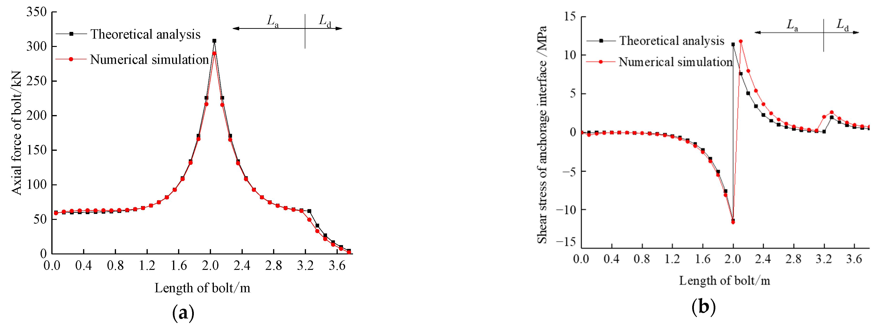
3.2. Model Verification
To verify the rationality of the above numerical model, theoretical calculation and numerical simulation were carried out. The axial force and interfacial shear stress of bolts were obtained, as shown in
Figure 4. Comparing the results of the theoretical and numerical calculations, it could be determined that the results of the two calculations agreed with each other. This indicated that the numerical calculation method was feasible.
4. Analysis of Mechanical Properties of Bolts under Typical Working Conditions
4.1. Single-Bed-Separation Conditions
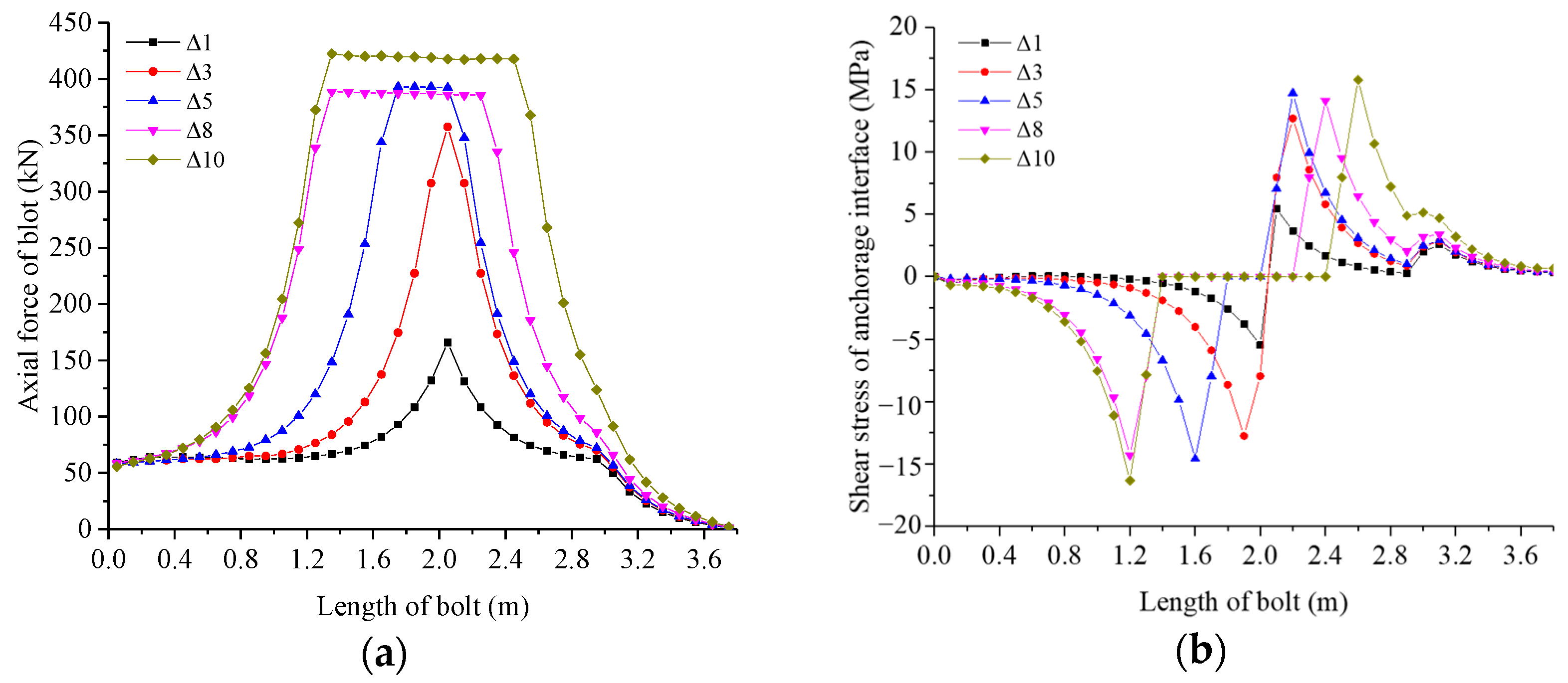
Only the middle fracture was set under the single-bed-separation condition, and the position of fracture was 2 m away from the left side of the bolt. Separately, the bed-separation values were taken as 1 mm, 3 mm, 5 mm, 8 mm and 10 mm. The axial force and interfacial shear stress of bolts were calculated under different bed-separation values, which are shown in
Figure 5. It can be seen from the simulation results that: (1) The bed-separation value has a significant effect on the axial force and shear stress of the anchorage interface. (2) When the bed-separation value is 1 mm or 3 mm, there is no sliding failure of the bolt; the larger the bed-separation value is, the greater the axial force and shear stress of the anchorage interface will be. (3) When the bed-separation value is 5, 8 or 10 mm, the sliding failure of the bolt begins to occur; the larger the bed-separation value is, the more the number of the sliding failure elements will be. (4) After the slip failure element of the bolt appears, an “equivalent platform” appears in the axial force variation diagram of the bolt; that is, the bolt axial force is evenly distributed in the unanchored part. Corresponding to the “equivalent platform”, the shear stress at the anchorage interface appears “zero value interval”.
It can be seen from
Figure 5a that the peak axial force of the bolt occurs at the bed separation, and the peak values were 165.8 kN, 357.3 kN, 392.2 kN, 385.9 kN and 417.6 kN, respectively. It also can be concluded that the peak values showed an overall increasing trend with the increase in the bed-separation value. Influenced by the anchoring agent, the axial force of the bolt decreased rapidly on both sides of bed separation. On the left side of the bed separation, the axial force attenuated to the initial prestress. However, the attenuation curve of axial force was divided into two sections on the right side, the initial bonding section and the secondary bonding section. In terms of attenuation rate, the axial force on the initial bonding section was less than that on the secondary bonding section.
In
Figure 5b, it can be seen that the interfacial shear stress on both sides of the bed separation was inverted. When there was no slip failure element on the bolt, the shear stress at the bed separation had peak values of 5.5 and 8.0 MPa, respectively, and the value of the peak value increased with the increase in the bed-separation value. On both sides of the bed separation, the shear stress showed a decreasing trend. On the left side of the bed separation, the shear stress decreased exponentially to zero. On the right side of the bed separation, the shear stress decreased exponentially on the secondary bonding section. In the initial bonding section, the shear stress increased first and then decreased. When the slip-failure element of the bolt occurs, the interfacial shear stress on both sides of the zero-value interval appeared at the peak values, which were 14.7, 14.3 and 16.3 MPa respectively. On both sides of the zero-value interval, the variation law of the shear stress was basically the same as that of the bolt without the slip-failure element.
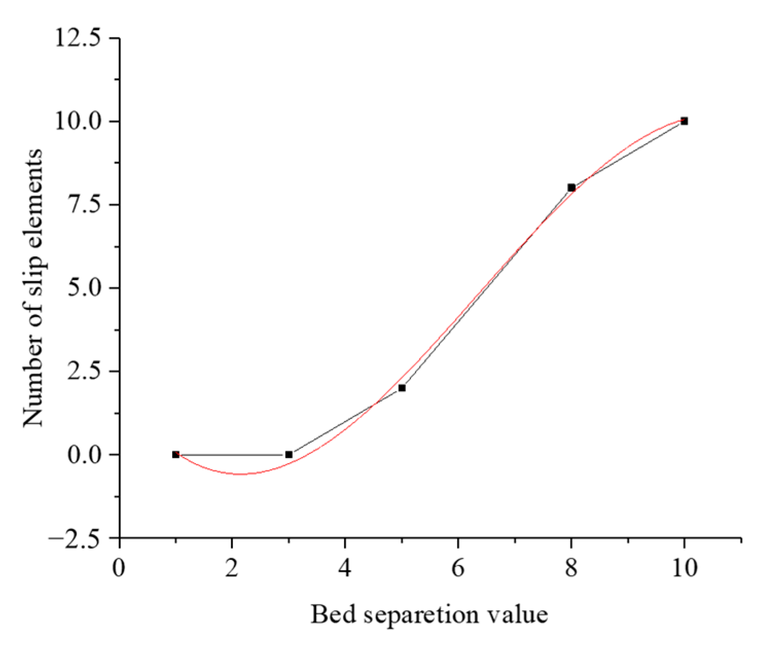
As shown in
Figure 6, the relationship curve between the bed-separation value and the number of slip-failure elements was drawn. Moreover, the curve function was obtained by polynomial fitting:
.
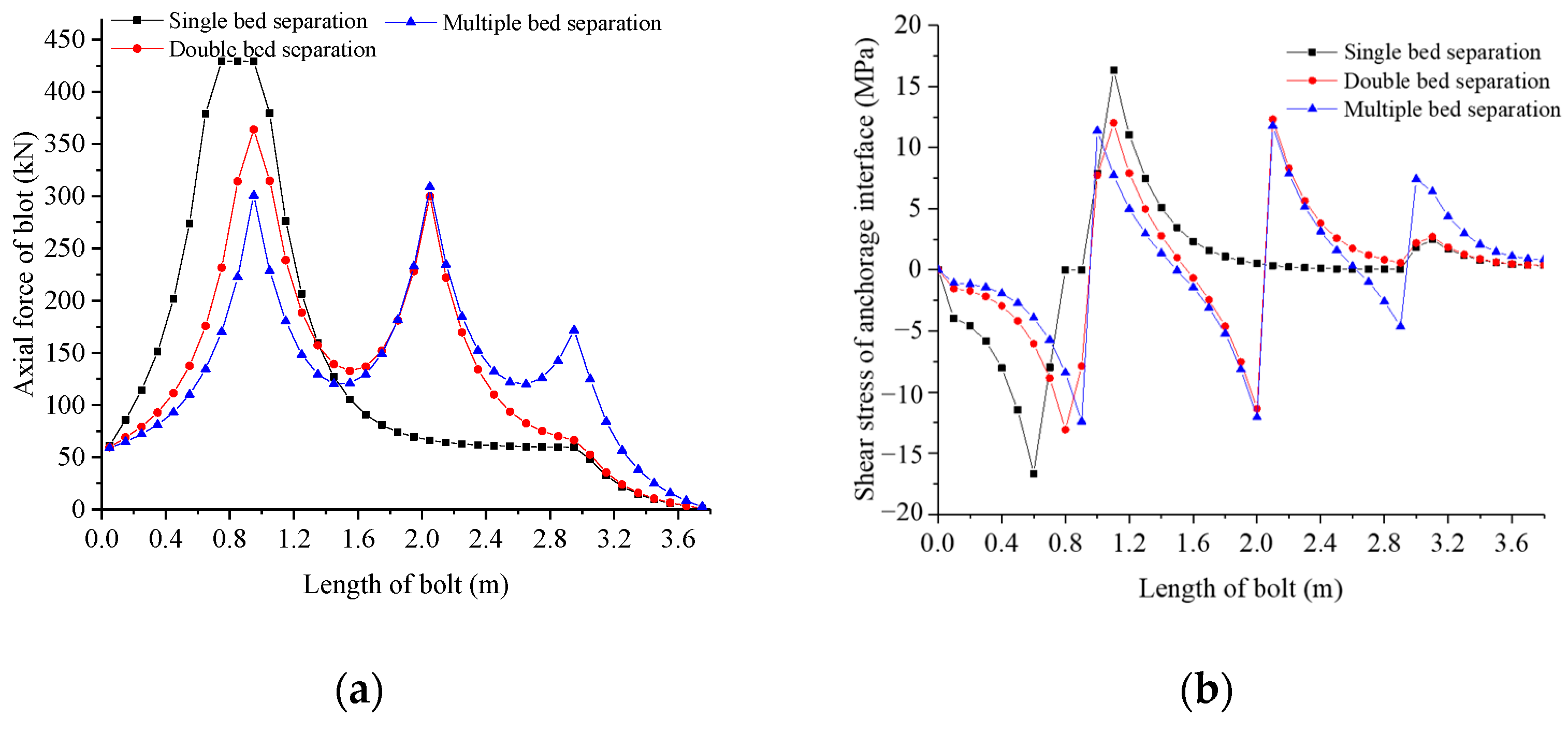
4.2. Multiple-Bed-Separation Condition
According to the bed-separation condition, single-bed separation, double-bed separation and three-bed separation were set separately. The single-bed-separation value was 5 mm with only the left crack. The double-bed-separation values were 3 mm and 2 mm, corresponding to the left and middle cracks, respectively. In addition, the three-bed-separation values were 2 mm, 2 mm and 1 mm, corresponding to the left, middle and right cracks. The calculation results of axial force and interfacial shear stress are shown in
Figure 7. From the simulation results, the number of bed separations had a significant effect on the axial force and interfacial shear stress. There was a slip-failure element under the single-bed-separation condition. In this situation, an “equivalent platform” appeared in the axial force. At the same time, the zero-value interval occurred in the interfacial shear stress. In addition, there was no slip failure in the double- and three-bed-separation conditions.
As shown in
Figure 7a, the axial forces of the bolt reached peaks at all bed separations. The peak axial force was 429.2 kN under the single-bed-separation condition, and the peaks were 363.9 kN and 299.8 kN under the double-bed-separation condition. Moreover, under the three-separation condition, the peaks were 300.7 kN, 308.9 kN and 171.7 kN, respectively. Under the double-separation condition, the axial force was attenuated to 132.8 kN. The effect of the initial bonding section on the attenuation law of the axial force of the bolt was the same as that of the single-bed separation. Moreover, the axial forces severally were attenuated to 120.4 kN and 119.9 kN under three-bed separation, and the influence of the initial bonding section on the axial force disappeared.
It can be seen from
Figure 7b that interfacial shear stresses reached their peaks on both sides of the bed separation, and its signs were reversed. The peak of interfacial shear stress was 16.7 MPa under the single-bed-separation condition. The interfacial shear stress attenuated to zero on the left side. On the right side of the bed separation, interfacial shear stress decreased exponentially on the secondary bonding section. However, interfacial shear stress increased first and then decreased on the initial bonding section. Under the double-bed-separation condition, the peaks of interfacial shear stress were 13.1 MPa and 12.3 MPa, respectively. The interfacial shear stresses on both sides of the bed separation gradually decreased. Moreover, the variation in shear stress on the initial bonding section was similar to that of the single-separation condition. Under the three-bed-separation condition, the peaks of interfacial shear stress were 12.4 MPa, 12.1 MPa and 7.4 MPa, respectively. The values of the shear stress on both sides of the bed separation gradually decreased, and the influence of the initial bonding section on the shear stress disappeared.
4.3. Different Bed-Separation Locations Condition
The bed separation was set as left crack, middle crack and right crack respectively, and the bed-separation value was 3 mm. The calculation results of the axial force and interfacial shear stress are shown in
Figure 8. We can see from the results that the right crack had a significant influence on the bolt, comparing it with the left and middle crack. Due to the small bed-separation value, there was no slip failure with three different separation locations. The variation laws of the axial force and interfacial shear stress were basically the same when the bed separations were the left and middle cracks. In terms of the right crack, the bed-separation location was close to the right end of the bolt, and the risk of overall slip failure was greater.
As seen in
Figure 8a, the peaks of axial force were 357.6 kN, 357.3 kN and 352.6 kN with three different bed-separation locations. The axial forces of the bolt on the left side of the bed separation decayed rapidly to the initial prestress values. This can be seen from both the left crack and the middle crack. However, on the right side of the bed separation, the axial force declined in two stages for the initial bonding section. Regarding the axial force of the right crack, it also decayed rapidly to the initial prestress value on the left side, but it decayed rapidly to zero on the right side. This feature was completely different from the left and middle cracks.
As shown in
Figure 8b, the interfacial shear stress on both sides of the bed separation was inverted, and reached the peak value at the bed separation. (1) The peak values of the interfacial shear stress were 12.7 MPa for both left- and middle-bed separation. On the left side of the bed separation, the interfacial shear stress decreased exponentially to zero. On the right side of the bed separation, the shear stress decreased exponentially on the secondary bonding section. On the initial bonding section, the shear stress increased first and then decreased. (2) In the right-bed separation, the peak value of the shear stress was 15.5 MPa, and the shear-stress value on both sides of the bed separation gradually decreased. The shear stress on the left side of the bed separation gradually tended to be gentle after attenuation, and the curve presented a long gentle section with a value close to zero. On the right side of the bed separation, the shear stress decreased exponentially, and the value after attenuation was 2.1 MPa.
5. Sensitivity Analysis Based on Orthogonal Test
5.1. Orthogonal Test Scheme and Calculation Results
According to the above analysis, the separation values, and the number and the locations of bed separation, are all important factors affecting the mechanical properties of the bolt. In order to reveal the influence of these three separation factors on the mechanical properties of bolts, an orthogonal test of three factors and three levels was designed, as shown in
Table 2.
Test indexes should not only be representative, but also meet the requirement of objectively evaluating the specific nature of the test object. In this paper, the number of slip-failure elements was taken as the evaluation index to evaluate the mechanical properties of a bolt. Range analysis [
30] and variance analysis [
31,
32] were used to analyze the sensitivity of three separate factors. The number of slip-failure elements was counted, as shown in
Table 1, after calculating nine groups of orthogonal tests.
5.2. Sensitivity Analysis Based on Range-Analysis Method
The range analysis reflects the dispersion degree of data [
33]. The greater the range, the greater the influence of level changes on the test results. The expression of the range method is:
where
Kij is the statistical parameter of
i-th level at the
j-th factor,
Rj is the difference between the maximum and minimum of
j-th factors,
kij is the average of
Kij, and
m is the level number of factors.
Using the above formula, the number of slip-failure elements was analyzed by the range method under three separation factors. The three separation factors were named A, B and C. The results of the orthogonal test are shown in
Table 3.
As seen in
Table 2, the number of slip-failure elements increased significantly with the increase in separation values. In terms of the sensitivity of the three separation factors, the separation value was the main factor affecting the number. Secondly, the number of separations had a certain effect on slip failure of the bolt. Finally, separation locations had the least effect. In actual engineering, it is necessary to reasonably adjust the anchor pitch and prestress, combined with the physical and mechanical properties of the surrounding rock. In this way, the separation values can be effectively reduced to ensure the safety of supporting engineering.
5.3. Sensitivity Analysis Based on Variance Analysis
The variance-analysis method can exclude the influence of experimental error, and determine the influence of different levels and the sensitivity of different factors [
33]. At the same time, it can also verify the results of range analysis. Although the variance-analysis method is also called multidirectional analysis of variance, its principle is basically the same as that of single factor [
34]. It is mainly used in hypothesis testing to judge whether multiple factors have significant influence on dependent variables. In multidirectional analysis of variance, the generalized linear model is often selected for parameter estimation. The formula is as follows:
where
Sj is the sum of squares.
According to the principle of variance analysis, the number of slip-failure elements under the conditions of the three separation factors was analyzed. The results are shown in
Table 4.
As is seen from
Table 3, the sensitivity of the three separation factors obtained by variance analysis was consistent with the results obtained by range analysis.
6. Limitations and Future Research Directions
(1) In this paper, all theoretical models and numerical models are only applicable when the bed separation is perpendicular to the bolt.
(2) In order to study the slip-failure characteristics under different conditions of bed separation, the parameters of the surrounding rock and the bolt were larger than those of the actual engineering.
The above limitations can be further discussed in future research. Especially, it would be more valuable and feasible to use the actual engineering model. In general, by using the numerical-simulation method, the variation law of the mechanical properties of full-grouted prestressed bolts was revealed under different conditions of bed separation. Moreover, the research results improved the theoretical system for full-grouted prestressed bolts. However, because of the above limitations, the reliability of the numerical-simulation results can be guaranteed only when the bed separation is perpendicular to the bolt.
7. Conclusions
(1) Different bed-separation parameters have significant effects on the mechanical properties of bolts, but in different ways. The number of slip elements is obviously affected by the value of the bed separation under the condition of single-bed separation. The greater the separation value, the greater the risk of the overall sliding failure of the bolt. Under the condition of multiple-bed separation, the number of the bed separations has an obvious effect on the peak axial force and shear stress when the total opening degree of the bed separations is the same. The greater the number of the bed separations, the smaller the peak axial force and shear stress. Under the condition of different bed-separation locations, the bed-separation location has a significant effect on the distribution of the axial force and shear stress on the initial bonding section. The distribution of the axial force and shear stress on the initial bonding section increases first, and then decreases, when it is left- and middle-bed separation. In the case of right-bed separation, the distribution of the axial force and shear stress on the initial bonding section decreases exponentially from the peak value.
(2) The range-analysis method and variance-analysis method based on an orthogonal test were used to reveal the influence degree of the three bed-separation factors on the mechanical properties of the bolt, namely, the value, number and location of bed separation. The range-analysis method and the variance-analysis method reached the same conclusion. The sensitivity order of the three bed separation factors was: bed-separation value > bed-separation number > bed-separation location, and the optimal combination was the bed-separation value being 3 mm, the bed-separation number being 2 and the location of the maximum bed-separation value being 2 m from the left end of the initial bonding section.
Author Contributions
Conceptualization, Z.Z.; methodology, F.S.; software, Z.L.; validation, X.W. and P.Z.; formal analysis, Z.Z.; investigation, Z.Z.; resources, F.S.; data curation, Y.G.; writing—original draft preparation, Z.Z. and F.S.; writing—review and editing, F.S. and Z.L.; visualization, X.G.; supervision, M.D.; project administration, X.G., P.Z. and M.D.; funding acquisition, X.G., P.Z. and M.D. All authors have read and agreed to the published version of the manuscript.
Funding
This research was funded by the Open-end Research Fund of State Key Laboratory for Geomechanics and Deep Underground Engineering [SKLGDUEK2024], the National Natural Science Foundation of China [52108371] and the National Natural Science Foundation of China [42177167], and the APC was funded by the National Natural Science Foundation of China [52108371].
Institutional Review Board Statement
Not applicable.
Informed Consent Statement
Not applicable.
Data Availability Statement
All relevant data are within the paper.
Conflicts of Interest
The authors declare no conflict of interest.
References
- Daraei, A.; Hama Ali, H.F.; Qader, D.N. Seismic retrofitting of rubble masonry tunnel: Evaluation of steel fiber shotcrete or inner concrete lining alternatives. Arab. J. Geosci. 2022, 15, 1074. [Google Scholar] [CrossRef]
- Sun, X.; Cai, F.; Yang, J. Numerical simulation of the effect of coupling support of bolt-mesh-anchor in deep tunnel. Min. Sci. Technol. 2009, 19, 352–357. [Google Scholar] [CrossRef]
- Liu, H.; Small, J.; Carter, J. Effects of tunnelling on existing support systems of perpendicularly crossing tunnels. Comput. Geotech. 2009, 36, 880–894. [Google Scholar] [CrossRef]
- Li, C.; Xu, J.; Li, M. The mechanical characteristics analysis of fully anchored prestressed bolts in coal mines. J. Min. Saf. Eng. 2013, 30, 188–193. [Google Scholar]
- Zhai, Y.D. The mechanics effect of bolt pretension in roadway surrounding rock. J. China Coal Soc. 2008, 33, 856–859. [Google Scholar]
- Fan, M.J. Study on Relationship between Bolt Pre-Stresses and Supporting Effect of Roadway; China Coal Research Institute: Beijing, China, 2007. [Google Scholar]
- Yang, S.S.; Kang, L.X. Study on the principle of bolt action and the feature of variable anchorage. J. Taiyuan Univ. Technol. 2003, 34, 540–543. [Google Scholar]
- Li, C.; Xu, J.; Fu, C. Mechanism and practice of rock control in deep large span cut holes. Min. Sci. Technol. 2011, 21, 891–896. [Google Scholar] [CrossRef]
- Wang, Q.; Wu, Y. Study on bolt pretension control in underground mine. Coal Sci. Technol. 2011, 39, 29–32. [Google Scholar]
- Kang, H.; Wang, J.; Lin, J. Case studies of rock bolting in coal mine roadways. J. China Coal Soc. 2010, 29, 649–664. [Google Scholar]
- Wu, Y. Application Study on Pre-stressed Full Length Bolting Powerful Support System. Coal Sci. Technol. 2011, 39, 27–30+35. [Google Scholar]
- Wang, Q.; Li, H. Study on the roof bedding separation and control measure of bolt-net supporting in coal roadway. Coal Mine Support. 2006, 4, 16–20. [Google Scholar]
- Feng, X. Failure Mechanism and Durability Exploration for Fully Bonded Bolting System. Ph.D. Thesis, China University of Mining and Technology, Xuzhou, China, 2017. [Google Scholar]
- Ding, X.; Gu, S.; He, H.; Zhang, Y. Force characteristic analysis of bolt under single and multiple bed separation. Rock Soil Mech. 2019, 40, 4299–4305. [Google Scholar] [CrossRef]
- Zhu, X.; Wang, D. Study of reinforcement mechanism of fully grouting rock bolt based on load transfer mechanism (I). J. Liaoning Tech. Univ. Nat. Sci. 2008, 27, 813–816. [Google Scholar]
- Wen, J.; Zhang, Y.; Wang, C. Study of mechanical model of fully grouted rock bolt’s anchorage interface in tunnel surrounding rock. Rock Soil Mech. 2013, 34, 1645–1652. [Google Scholar]
- Yu, Y.; Chen, B.; Zhang, T. Deformation law and flexible formwork support technology of soft rock tunnel based onforce analysis of rock bolt. China J. Highw. Transp. 2018, 31, 254–263. (In Chinese) [Google Scholar]
- Cui, L.; Zheng, J.; Sheng, Q. A Simplified Procedure for the Interaction Between Fully-grouted Bolts and Rock Mass for Circular Tunnels. Comput. Geotech. 2019, 106, 177–192. [Google Scholar] [CrossRef]
- Liu, G.; Xiao, M.; Chen, J. Stress analysis method of fully grouted rock bolt in underground caverns. J. Huazhong Univ. Sci. Technol. Nat. Sci. Ed. 2017, 45, 113–119. [Google Scholar]
- Ma, S.; Zhao, Z.; Nie, W. A Numerical Model of Fully Grouted Bolts Considering the Tri-linear Shear Bond-Slip Model. Tunn. Undergr. Space Technol. 2016, 54, 73–80. [Google Scholar] [CrossRef]
- Shang, F.; Wang, X.; Zhu, Z.; Zhang, P.; Du, M.; Yu, K.; Yuan, C.; Guan, X. Law of Mechanical Properties of Full-Length Bonded Prestressed Bolts Influenced by Design Parameters. Processes 2023, 11, 1221. [Google Scholar] [CrossRef]
- Ding, X. Research on Bolt Load Transfer Mechanism under Bed Separation Effect and Its Support Design. Ph.D. Thesis, Xi’an University of Science and Technology, Xi’an, China, 2016. [Google Scholar]
- Lü, A.; Liu, Y.; Zhang, X. A theoretical solution for acircular tunnel reinforced by fully grouted rock bolts. Chin. J. Rock Mech. Eng. 2018, 37, 1561–1573. [Google Scholar]
- Yuan, Y.; Xiao, M.; Chen, J. A method for simulating stress distribution along fully grouted anchor. Rock Soil Mech. 2018, 39, 371–379. [Google Scholar]
- Chang, X.; Li, Z.; Wang, S. Pullout Performances of Grouted Rockbolt Systems with Bond Defects. Rock Mech. Rock Eng. 2018, 51, 861–871. [Google Scholar]
- Teymen, A.; Kılıç, A. Effect of grout strength on the stress distribution (tensile) of fully-grouted rockbolts. Tunn. Undergr. Space Technol. 2018, 77, 280–287. [Google Scholar] [CrossRef]
- Yang, H.; Feng, X.; Yan, S. Experimental research on full-length anchoring system based on a new type of cement based material. Saf. Coal Mines 2021, 52, 89–94+101. (In Chinese) [Google Scholar]
- Gu, S.; Ding, X. Elastic analysis on roadway roof bed separation affected to bolt loading. Coal Sci. Technol. 2012, 40, 33–36. [Google Scholar]
- Wang, X.; Yang, J.; Li, J.; Yang, L. Analysis of mechanical properties of fully-grouted bolts considering de-bonding under typical conditions. J. Coal 2020, 45, 599–608. [Google Scholar]
- Fang, K.; Ma, C. Orthogonal and Homogeneous Experimental Design; Science Press: Beijing, China, 2001. (In Chinese) [Google Scholar]
- Mao, S.; Wang, J.; Shi, D. Statistics Handbook; Science Press: Beijing, China, 2003. [Google Scholar]
- Wu, H.; Yu, J.; Shi, C. Sensitivity analysis for parameters of buried steel pipes based on orthogonal test method. J. Yangtze River Sci. Res. Inst. 2021, 38, 97–103. [Google Scholar]
- Xue, X.; Ou, J.; Lin, X. Sensitivity analysis of anti-explosion structure parameters of civil aircraft based on orthogonal experiment. Adv. Aeronaut. Sci. Eng. 2023, 1–13. [Google Scholar]
- Xu, B. Simulation Study on the Failure Law and Protection Effect of Blast under the Action of Explosion. Master’s thesis, Shenyang Ligong University, Shenyang, China, 2022. [Google Scholar]
| Disclaimer/Publisher’s Note: The statements, opinions and data contained in all publications are solely those of the individual author(s) and contributor(s) and not of MDPI and/or the editor(s). MDPI and/or the editor(s) disclaim responsibility for any injury to people or property resulting from any ideas, methods, instructions or products referred to in the content. |
© 2023 by the authors. Licensee MDPI, Basel, Switzerland. This article is an open access article distributed under the terms and conditions of the Creative Commons Attribution (CC BY) license (https://creativecommons.org/licenses/by/4.0/).


 ,
, 


