Abstract
To achieve high precision, stability, and good surface quality when producing micro-dimple arrays on cylindrical surfaces, we propose a new processing method known as radial ultrasonic rolling electrochemical micromachining (RUREMM) in this study. This method is based on the electrochemical micromachining (EMM) and ultrasonic machining principle. The relevant simulation model was created, and ANSYS researched the flow field characteristics of the electrolyte between the array electrodes and the workpiece. Micro-dimple arrays were created on a SS304 cylindrical surface with the consideration of the effects of the machining parameters, including ultrasonic amplitude and applied pulse voltage. Compared with the EMM, the average width of the micro-dimples is reduced by 24.5%, the aspect ratio of the dimple is increased by 108.0%, and the surface roughness of micro-dimples is decreased by 59.7%. In addition, the localization and the surface quality of micro-dimples by RUREMM can be improved when using appropriate machining parameters.
1. Introduction
Textured surfaces with specific micro-grooves, micro-dimples and other special morphologies exhibit improved temperature resistance, corrosion resistance, lubrication performance and friction for various mechanical components [1,2,3]. The fabrication of microstructures has drawn significant attention from scholars in the fields of tribology, air vehicle manufacturing and industrial chemistry. For example, Walker et al. demonstrated a 37% reduction in the coefficient of sliding friction in Al-Si cylinder liner material by applying surface features [4]. Hao et al. [5] proposed that arrays of micro-concavities produced on the planar and cylindrical inner surfaces of metal are conducive to increasing dynamic pressure and decreasing resistance. In recent decades, non-traditional machining processes, including laser machining (LSM) [6,7,8,9], micro-electrical discharge machining (EDM) [10,11,12,13,14], and electrochemical micromachining (EMM) [15,16,17,18], have gained significant attention for improving the surface properties of metals. EMM is considered a cutting-edge micro manufacturing method that uses electrochemical anodic dissolution to remove material from a workpiece. This approach offers numerous benefits, including a high material removal rate, and the avoidance of residual mechanical stress on the workpiece [19,20,21,22]. In recent years, EMM has developed and diversified, resulting in various methods, including electrochemical jet machining (EJM). EJM is an electrochemical micromachining process that employs a nozzle cathode to deliver the electrolyte, generating a jet that impinges onto the anodic workpiece [23]. In addition, Wang et al. demonstrated that the electrochemical jet apparatus not only removes material from a workpiece, but also performs localized electro deposition to build complicated 3-dimensional structures. This is achieved by modifying the cathode nozzle to dispense a deposition solution instead of an electrolyte [24]. Through-mask electrochemical micromachining (TMEMM) is a process in which a substrate is covered with a nonconductive, patterned mask. The mask allows the electrolytic solution to selectively etch or deposit material only in areas where the mask is absent, thereby creating a microstructure [25]. Patel et al. [26] utilized through-mask electrochemical micromachining (TMEMM) to fabricate micro-dimples on a stainless-steel substrate. They were able to create a total number of 100 micro-dimples using this method, with an average diameter and depth of 150 μm and 15 μm, respectively. Air-shielding electrochemical micromachining (AS-EMM) is a novel technique for fabricating microstructures. It involves the use of a coaxial gas jet to help shield the workpiece from the electrolyte, which can improve the precision and quality of the microstructures produced. During AS-EMM, the coaxial gas jet is used to provide a layer of shielding gas around the electrolyte jet, which minimizes turbulence and prevents the hydraulic jump from occurring too close to the impact area. This allows for more accurate machining and improved surface finish [27,28].
Despite the potential advantages of using techniques like AS-EMM for micro-dimple processing, achieving optimal machining localization remains a major challenge. Due to the small size of the high-pressure electrolyte stream used in the process, it can be difficult to control the machining and achieve the desired location, leading to uneven surface finishes and imperfect microstructures.
Currently, there is a growing awareness among scholars about the potential benefits of incorporating ultrasound assistance in various machining processes [29,30]. Wang et al. [31] have demonstrated that the use of ultrasonic energy fields can significantly enhance machining efficiency and stability. By introducing ultrasonic vibrations, they were able to fabricate micro-holes with an aspect ratio of 12.3. Wu et al. [32] demonstrated that hybrid ultrasonic vibration is effective in reducing grinding forces and chip adhesion on the grinding wheel. Moreover, this technology improves surface quality and the material removal ratio. Goel et al. [33] observed that increasing the ultrasonic vibration time in the ultrasonic-assisted jet electrochemical micro-drilling process resulted in an increase in the material removal rate of the workpiece, while the hole taper decreased. Singh et al. [34] conducted research that demonstrated the beneficial effects of combining high electrochemical discharge energy with ultrasonic assistance in achieving higher material removal rates and depth-to-diameter ratios. This is due to the parallel provision for the evacuation of sludge/debris and electrolyte replenishment in the machining zone. Zhao et al. [35] proposed that the ultrasonic modulating compound electro-discharge and electrochemical mine fine machining system works reliably, and can effectively enhance gap management. Li et al. [36] discovered that using optical parameters in ultrasonic-assisted electrochemical drilling yields a higher degree of accuracy and removes more materials.
In view of the electrochemical micromachining and ultrasonic machining principle, radial ultrasonic rolling electrochemical micromachining (RUREMM) was presented to machine micro-dimples on a SS304 plate. A simulation model was developed to examine the flow field characteristics of the electrolyte between the array electrodes and the workpiece during the RUREMM process. The analysis of the flow field characteristics was carried out using ANSYS FLUENT software [37,38]. Micro-dimple arrays were created on a cylindrical surface, taking into consideration the effects of the machining parameters, including applied pulse voltage and ultrasonic amplitude. Furthermore, this study provides a comprehensive discussion on the localization and surface quality achieved through RUREMM, in comparison to the performance of electrochemical micromachining (EMM).
2. Principle of the EMM and the RUREMM
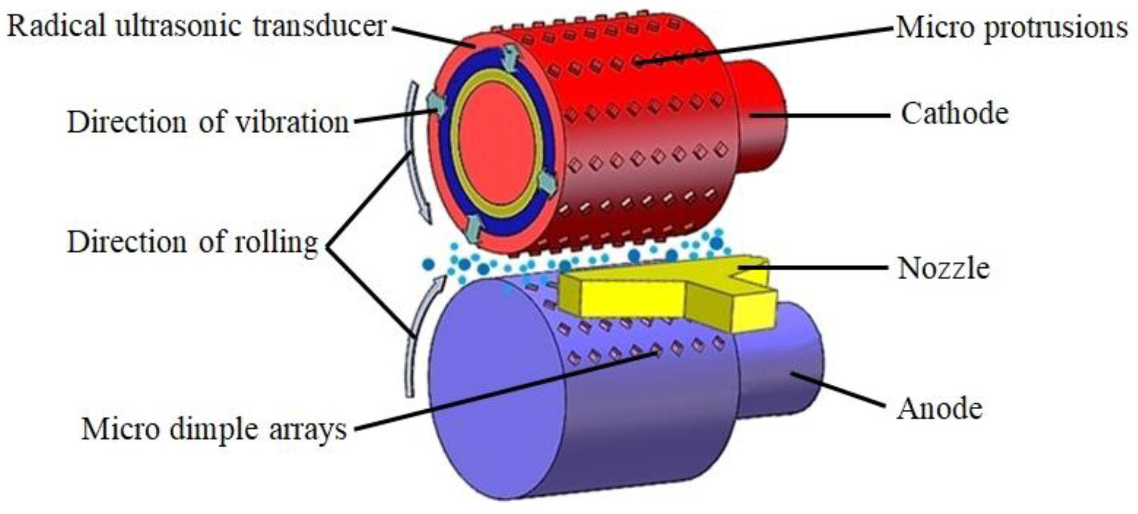
In RUREMM, the cathode includes an ultrasonic transducer with micro-protrusions on its surface, while a cylindrical workpiece made of SS304 serves as the anode, as illustrated in Figure 1. The ultrasonic transducer (cathode) and the workpiece (anode) are clamped on different spindles of the machine tool, respectively, which has the same linear velocity during machining. The conductive electrolyte is pumped into the machining zone by the nozzle, serving as the medium [37]. Micro-dimples are formed on the workpiece surface when the power is connected, and the radial ultrasonic transducer produces an array of micro protrusions that vibrate to assist in the machining process.
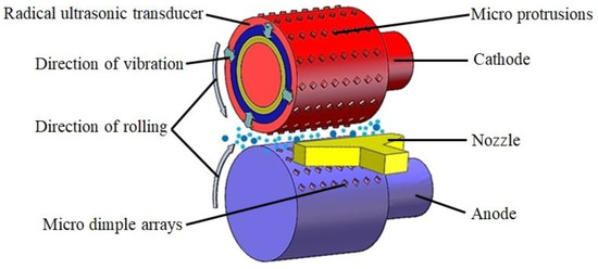
Figure 1.
The schematic diagram of RUREMM.
Figure 2a demonstrates the anodic dissolution pits formed on the surface of the anode with varying depths. These pits result in a decrease in surface roughness and the accumulation of electrolytic products. In contrast, Figure 2b shows that ultrasonic cavitation initiates a chain reaction of cavitation bubbles that collapse and break the passive layer on the workpiece surface. This results in the formation of plastic micro-pits and micro-jets on the metal surface, along with convex peaks surrounding the pits in the machining gap. As a result, the plastic peaks serve to amplify the impact of the electric field in the machining gap, leading to a smoother and better surface finish [39].
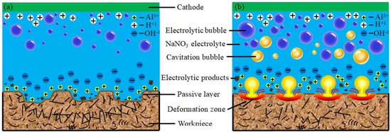
Figure 2.
Schematic model of material anodic dissolution. (a) EMM, (b) RUREMM.
3. Mathematic Model
During RUREMM, the tool undergoes rapid vibrations at the equilibrium position, while the frontal machining gap undergoes periodic variations. Additionally, the gap between the micro-protrusions on the tool and the workpiece can be described as the frontal gap,
where Δz is the equilibrium gap, ω is the angular velocity and φ is the phase symbol. In EMM, the material removal on the anode can be computed based on Faraday’s law,
where η is the current efficiency of anodic dissolution, ω is the electrochemical equivalent of the workpiece material, κ is the electrolyte conductivity with tool vibration, E is the electric field intensity, ΔU is the total overpotential between cathode and anode, and Δb is the frontal gap. In EMM, the conductivity of the electrolyte plays a crucial role in the distribution of the electric current within the interelectrode gap. However, this conductivity can be significantly impacted by the byproducts that form in the narrow machining gaps, such as hydrogen and sludge [27],
where κ0 is the original value of electrolyte conductivity, T0 is the original temperature and β is the void fraction of gas in the machining gap. According to the theoretical model that considers the influence of the electric field and the first law of Faraday on the machining gap during RUREMM, the material removal rate (MRR) can then be determined as follows,
where I is the current density in the machining gap, M is the molar mass, n is the valence of substance, F is the Faraday constant, and S is the machining area. In addition, the ultrasonic vibration of the cathode can significantly alter the liquid flow field. As a result, the theoretical material removal rate of the workpiece can be obtained, which is observed to increase with the tool vibration during RUREMM.
4. FEM Simulation
In order to get the flow field velocity in the interelectrode gap, the relevant simulation model was created, and Fluent was employed to analyze the flow field characteristics of the electrolyte between the array electrodes and the workpiece.
4.1. Model Description
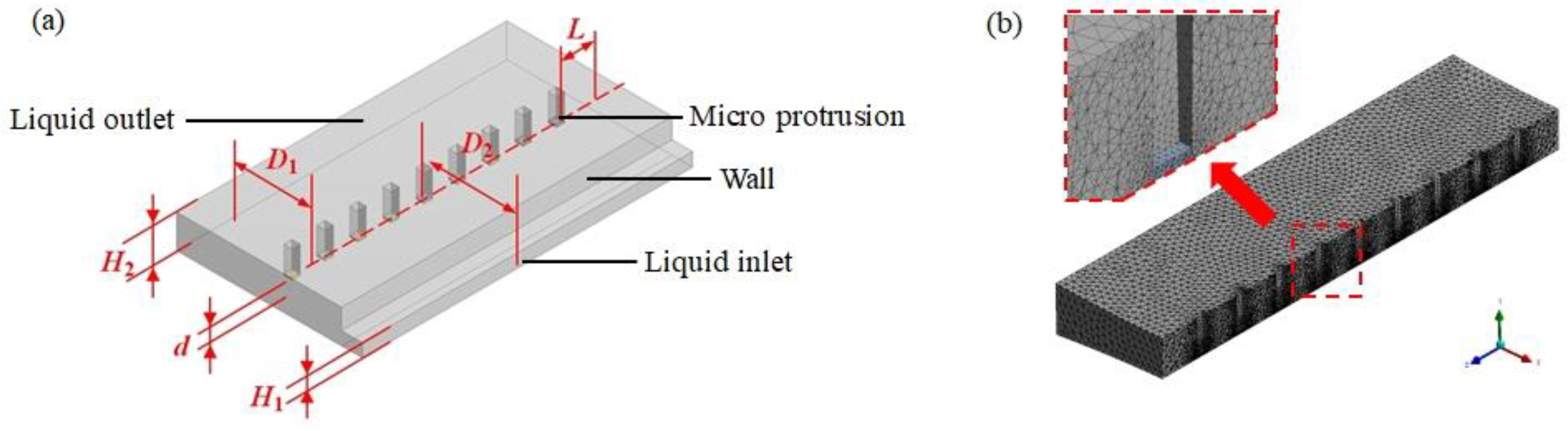
Figure 3a describes the developed physical model during processing. The electrolytic aqueous solution is ejected on the machining area between the vibrating electrode and workpiece from the right location, exiting through the model boundary without backflow. The relevant parameters are listed in Table 1.

Figure 3.
Simulation model. (a) Physical model, (b) meshed model.

Table 1.
Boundary conditions of the numerical model.
When applying the ultrasonic energy field, the flow field in the machining gap is unstable, whereas the flow around the boundary is gentle. Therefore, the local mesh was refined from dense to sparse from the flow center to the boundary [40,41,42]. This can improve computational efficiency and ensure accuracy, as shown in Figure 3b. According to the previous research, the initial velocity of the electrolyte is assumed to be 3 m/s.
4.2. Simulation Result
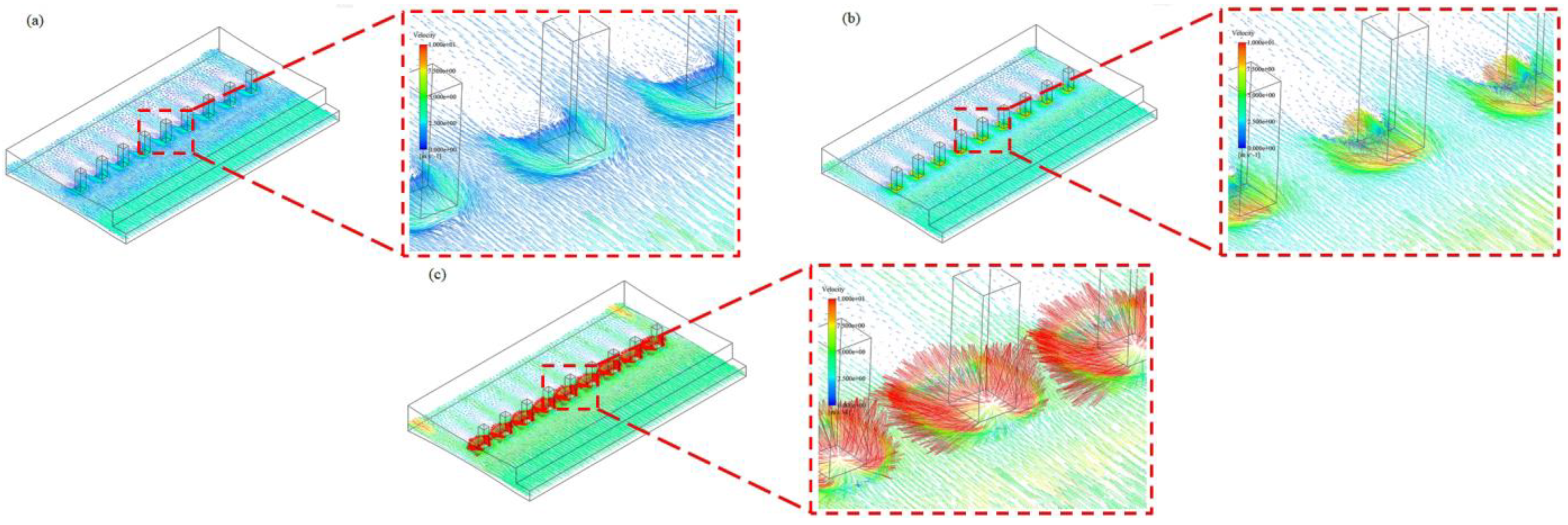
Figure 4 depicts the complete velocity vector of the liquid in an axonometric drawing, with the aqueous solution entering from the right side. The figure shows that the electrolyte from the nozzle flows effectively through the machining gap, with a relatively uniform distribution.
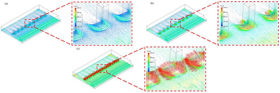
Figure 4.
Velocity vector of the flow field. (a) EMM, (b) RUREMM (upward vibration), (c) RUREMM (downward vibration).
During EMM, the flow velocity of the electrolyte decreases due to the resistance effect of square electrodes, as evidenced in the decreasing flow arrows in Figure 4a. However, the bottom flow field remains relatively stable. Furthermore, Figure 4b illustrates an increasing machining gap, as well as a distinct blue reflux zone formed by the rapid upward displacement of the ultrasonic transducer. In addition, the velocity of the electrolyte is increased, which has the same direction as the flow field, and the other region has the lower velocity which decreases with the opposite direction. Once the cathode has reached its furthest possible position in relation to the workpiece surface, and the machining gap has been minimized during the machining process, this indicates that the cathode has made its closest approach to the workpiece. In Figure 4c, it can be observed that the flow rate of the electrolyte surrounding the tool electrode experiences a significant increase as a result of the powerful, instantaneous impact generated by the tool electrode. This impact causes the electrolyte to be continuously flushed out. Furthermore, the velocity of the electrolyte is simultaneously reduced in the opposite direction to the tool electrode’s movement.
According to Figure 5, the variation in flow field velocity within the machining gap is depicted. When there is no vibration, the velocity of the electrolyte experiences an increase of approximately 152.0% and 246.8%, ranging from 2.52 m/s to almost 6.35 m/s, and 8.74 m/s when the cathode rapidly moves both upward and downward. Based on these results, it can be inferred that the flow rate of the electrolyte in the machining gap is substantially improved through the introduction of the ultrasonic energy field, which can promptly renew the electrolyte, and thus significantly enhance machining accuracy.
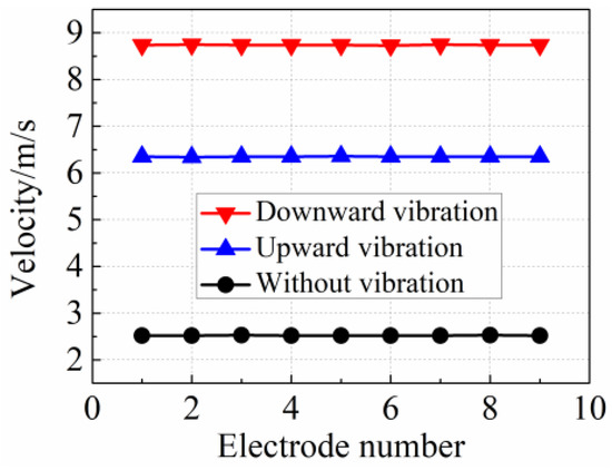
Figure 5.
Variation of flow field velocity in the machining gap.
5. Experimental System and Design
5.1. Experimental Equipment
Figure 6 shows a schematic view of the experimental equipment. The experimental configuration comprises the ultrasonic generation system, electrolyte recycle, pulse power supply, and the machine tool control system. The ultrasonic transducer is a crucial component of the ultrasonic generation system. It converts electrical energy into ultrasonic waves; the ultrasonic waves cause the tool to vibrate radially, which helps to improve the efficiency and effectiveness of the electrochemical machining process. A radical vibration transducer with micro protrusion on its outside surface is used as the cathode, which is fixed on the different revolving stage. The electrolyte module provides the electrolyte solution at a specific pressure that can be adjusted using valves, pumps, and filters. This system effectively controls the velocity and flow of the electrolyte solution within the processing loop. Power supply units supply the machining current at different parameters: voltage and duty ratio (USIMU, TP3030). The computer system precisely controls the motion of the XYZ axes connected to three servomotors through a motion control card. In addition, a high-speed camera (Keyence, VW6000) is applied to detect the machining gap. This ensures that the inter-electrode gap is maintained within specified tolerances, resulting in accurate and efficient electrochemical machining.
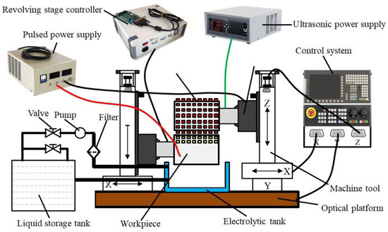
Figure 6.
Experimental equipment of RUREMM.
The experiment parameters are listed in Table 2. The cathode has the same linear velocity as the anode, EMM and RUREMM can be carried on.
Table 2.
Experimental conditions.
5.2. Experimental Design
The experiment was divided into three parts. In the first part, the localization, and stability of the workpiece surface were compared to the same machining condition by EMM and RUREMM. To ensure optimal efficiency and effectiveness of the machining process, it is necessary to polish the stainless steel plate to remove any naturally formed oxide films or other surface contaminants from the SS304 tube prior to machining. This can be achieved by finishing the outer wall of the tube using a mechanical or chemical process. The second part of the study focused on investigating the impact of machining parameters, such as ultrasonic amplitude and applied pulse voltage on the width, aspect ratio, and surface roughness of the dimples. Through comprehensive experiments and analysis, the researchers were able to establish clear rules outlining the influence of these parameters on each of the target characteristics. In the third part of the study, the optimized parameters that were identified in part II were used to fabricate an array of micro-dimples on the surface of a cylindrical SS304 tube.
6. Experimental Results and Discussion
6.1. Basic Experimental Results and Analysis by EMM and RUREMM
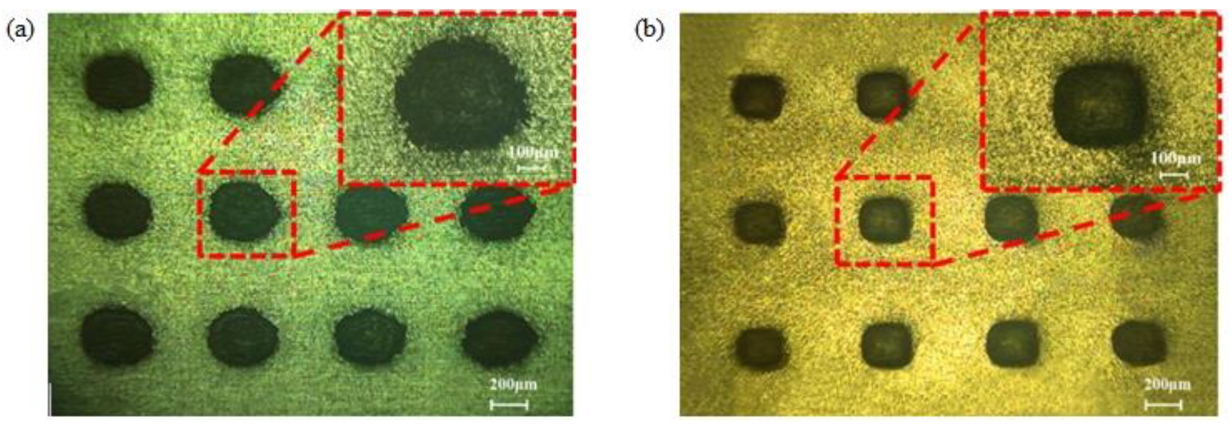
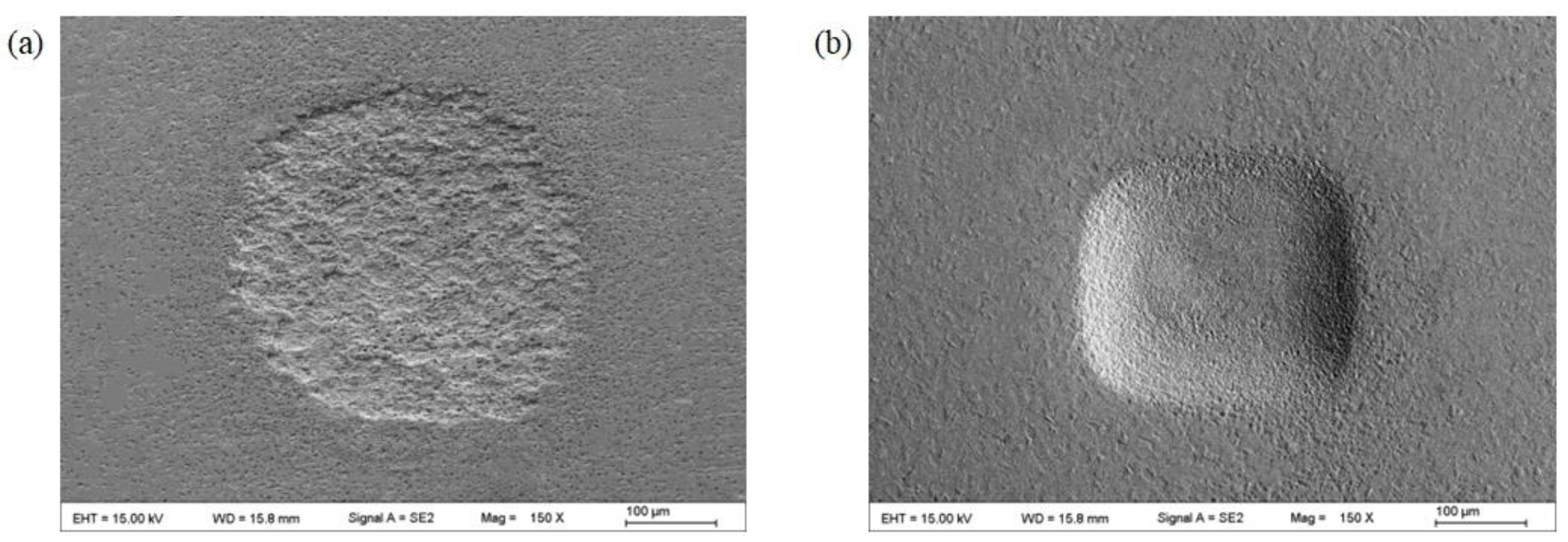
To compare the localization and stability of workpieces machined using EMM and RUREMM, a series of basic experiments were conducted. The ultrasonic amplitude is 10 μm and the pulse voltage is 10 V, as shown in Figure 7 and Figure 8. The morphology and dimensions of the machined array dimples were analyzed using two different techniques: scanning electron microscopy (SEM) (Hitachi, Regulus 8100) and optical profiler (KLA, Zeta-300). In the field of electrochemical micromachining (EMM), it is observed that the surface of micro-dimples often has blurred boundaries with the rough bottom. This is because the electrochemical process can result in uneven removal of material from the surface, leading to an irregular shape of the dimple. Based on the micro-dimples processed using RUREMM, as shown in Figure 7b andFigure 8b, it seems that there is a more uniform corrosion on the surface of the micro-dimples. This might be because RUREMM combines the benefits of rotary ultrasonic machining and electrochemical machining, resulting in a more uniform and controlled material removal. Moreover, the absence of any unremoved material in the central area of the dimple indicates that the machining process is more precise and controlled. Overall, RUREMM shows promise as a micromachining technique for producing high quality micro-dimples with improved surface quality and dimensional accuracy.

Figure 7.
Array dimples. (a) EMM, (b) RUREMM.
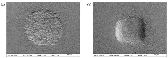
Figure 8.
Enlarged view of a single dimple. (a) EMM, (b) RUREMM.
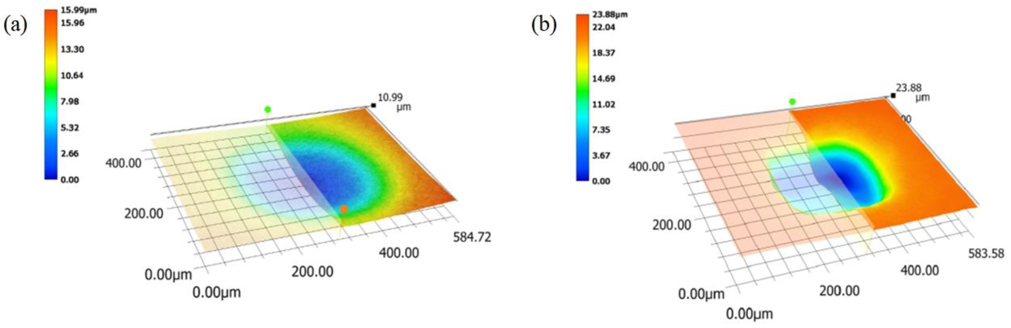
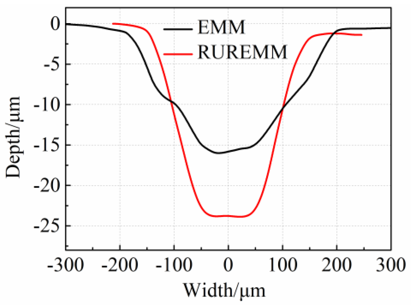
The 3D morphology and cross-sectional profile curves of micro-pits are captured in Figure 9 and Figure 10. In comparison to EMM, RUREMM offers several advantages. It provides clearer fringing, larger dimple taper, and smoother profile curve, resulting in improved control over dispersive corrosion, better localization, and increased accuracy in measurement. The reason for these results is due to the continuous impacting effect of the micro-jets, which is achieved through the excitation of ultrasonic vibrations. This continuous impact of the micro-jets causes the micro-dimples to become deeper, resulting in the improved characteristics of RUREMM.
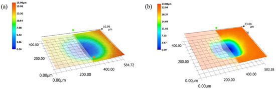
Figure 9.
3D morphology of micro-pits. (a) EMM, (b) RUREMM.

Figure 10.
Cross-sectional profile curves during EMM and RUREMM.
In addition to making the micro-dimples deeper, the continuous impacting effect of the micro-jets also causes plastic peaks to form around the edge of the pits. This, in turn, creates a more concentrated electric field and an increase in the current density in the machining gap, leading to a smoother surface finish. The plastic peaks act as barriers to the discharge, helping to prevent the formation of micro-cracks and the re-erosion of previously machined areas. Altogether, this results in an improved surface finish in the RUREMM process. The roughness of the micro-dimples obtained at different conditions by 3D profiler and the roughness of the smooth surface (Ra), is decreased by 59.7% from 0.549 μm to 0.221 μm compared to EMM.
In order to study the consistency of the array micro-dimples, the width and depth of 12 dimples were measured one by one. Table 3 and Table 4 present the dimensions (width, depth), average value and the standard deviation. The standard deviation of width and depth of all the dimples is shown in Table 4.
Table 3.
Dimensions value list by EMM and RUREMM.
Table 4.
Analysis of results by EMM and RUREMM.
In EMM, the width and depth deviations (the maximum deletes the minimum) were found to be 23.1 and 1.8 μm, respectively. Similarly, the diameter and depth deviations in RUREMM were found to be 14.3 and 1.2 μm, respectively. Furthermore, compared to EMM results, it was observed that the average width of the dimples decreased by 24.5%, and the aspect ratio of dimple depth to width increased by 108.0%. Furthermore, it can be observed that the population standard deviation has decreased. These findings indicate that the use of RUREMM is effective in enhancing consistency and stability, while reducing variability in dimple size.
6.2. Effect of Machining Parameters on Array Micro-Dimple Dimensions
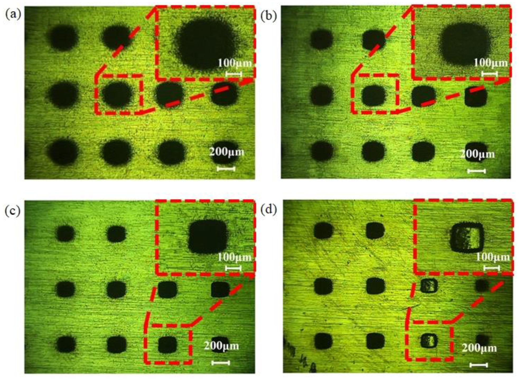
During RUREMM, ultrasonic vibration can effectively improve the flow field distribution in the machining gap, and can quickly remove insoluble products and joule heat generated during the processing. The ultrasonic amplitude is the essential factor required to improve the machining accuracy and surface quality of micro textures. Figure 11 and Figure 12 illustrates the morphology of array micro-pits and the effects of ultrasonic amplitude on the width and depth. The ultrasonic voltage is 5, 10, 15 and 20 μm, the aspect ratio of micro-dimples, respectively, which were generated by RUREMM. As the ultrasonic amplitude increases, the stray corrosion phenomenon of micro-pits decreases, obviously while the localization increases.
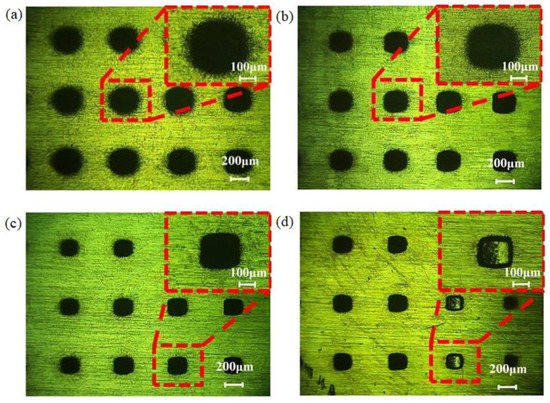
Figure 11.
Morphology of array micro-pits under different ultrasonic amplitude during RUREMM. (a) 5 μm, (b) 10 μm, (c) 15 μm, (d) 20 μm.

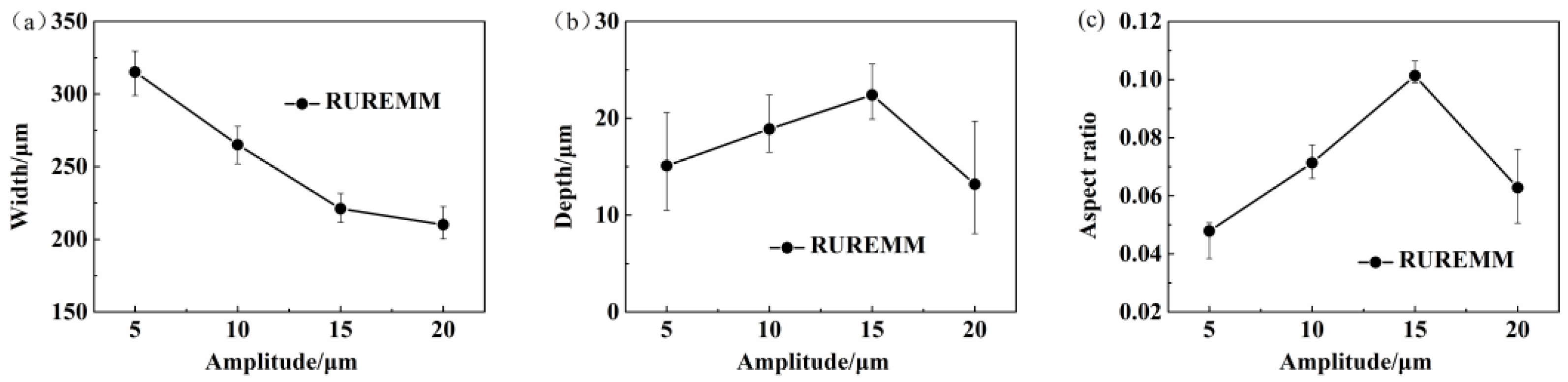
Figure 12.
Effects of ultrasonic amplitude on array dimple dimensions during RUREMM. (a) Width, (b) depth, (c) aspect ratio.
The change in ultrasonic amplitude has a great influence on the width and depth of the dimples. According to Figure 12, it is evident that when the ultrasound amplitude increases from 5 μm to 20 μm, the average width of the array microcavities decreases from around 315.2 μm to around 210.1 μm—a decrease of 105.1 μm, which is approximately 33.3%. Meanwhile, the aspect ratio obviously increases with the ultrasonic amplitude. This is because the ultrasonic amplitude has a great effect on the intensity of the ultrasonic energy, which can enhance the cavitation and the flow field distribution, and ultimately improve the dissolution rate of the material. The higher ultrasonic amplitude makes the machining quality unstable (Figure 11d), and frequently causes direct contact between electrodes and a workpiece. The experimental results suggest an optimal ultrasonic amplitude is 15 μm.
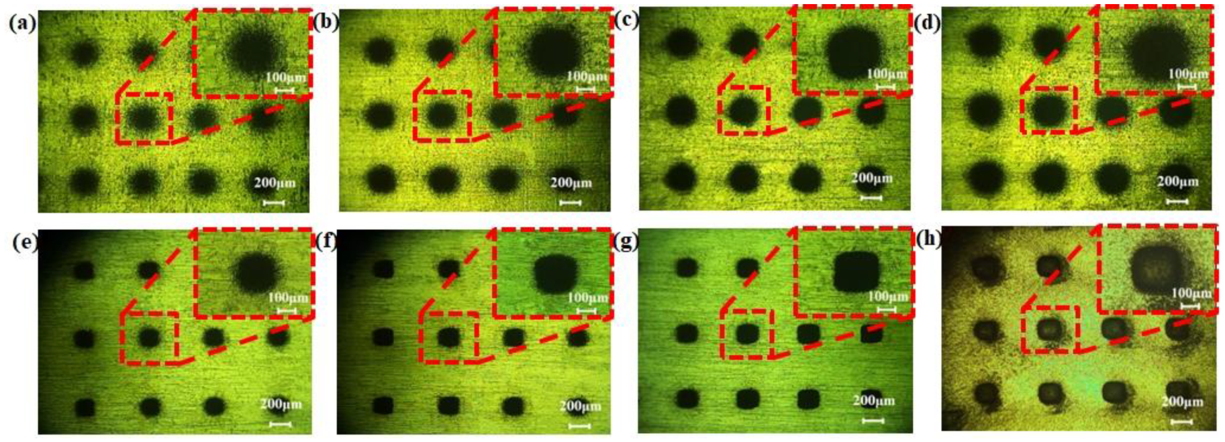
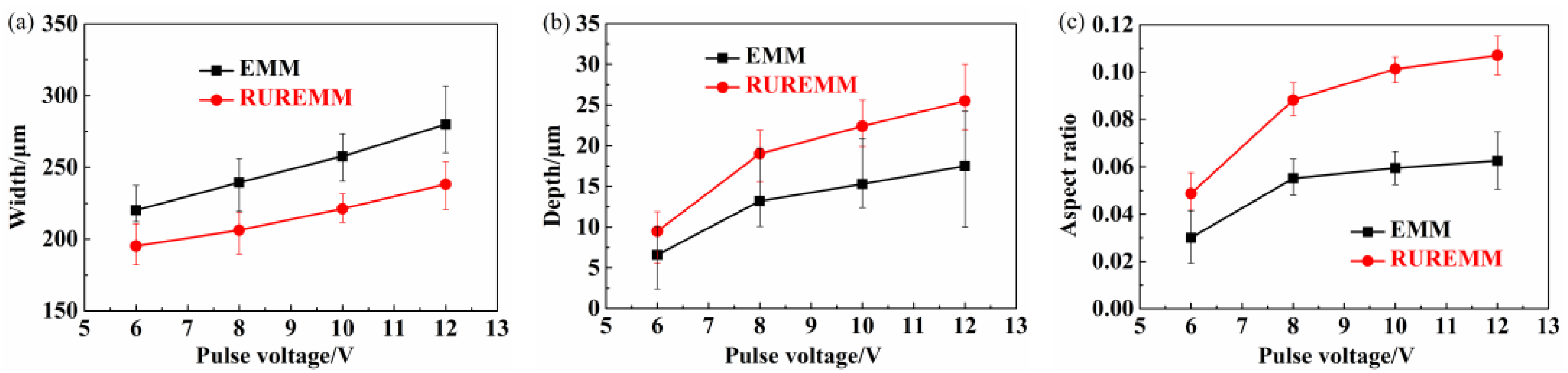
Figure 13 and Figure 14 show the morphology and the relationship between pulse voltage and dimensions of the array micro-dimples, respectively, under different pulse voltage during EMM and RUREMM. During the RUREMM, the phenomenon of the stray corrosion decreases, and the fringing is clearer with higher surface precision as the pulse voltage increases. The change of pulse voltage has little influence on the width of the dimples, and EMM and RUREMM have a similar variation in the same working conditions.

Figure 13.
Morphology of array micro-pits under different pulse voltage, EMM: (a) 6 V, (b) 8 V, (c) 10 V, (d) 12 V, RUREMM: (e) 6 V, (f) 8 V, (g) 10 V, (h) 12 V.
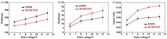
Figure 14.
Effects of pulse voltage on array dimple dimensions during EMM and RUREMM. (a) Width, (b) depth, (c) aspect ratio.
As the pulse voltage increases, the depth and aspect ratio increase, while the width decreases. These phenomena can be attributed to the ultrasonic energy field which is capable of removing the electrolytic products, improving the whole current density, and improving the localization effectively. In addition, it was observed that a lower voltage failed to provide the required machining current density (as shown in Figure 13a,e), whereas a higher voltage resulted in excessive secondary dissolution and a less distinct profile (as seen in Figure 13d,h). However, increasing the voltage leads to a higher material removal rate, which can have a negative impact on the bottom surface quality. The experimental results suggest an optimal applied pulse voltage is 10 V.
6.3. Array Micro-Dimples Fabrication by the Optimized Parameters
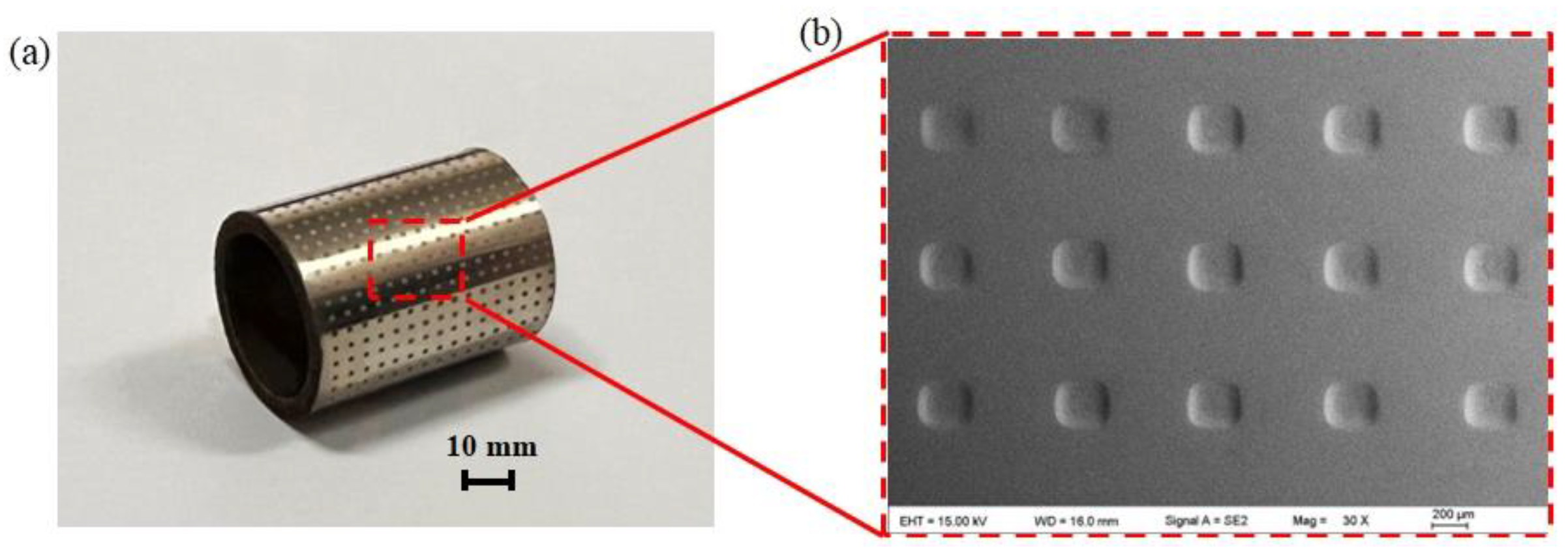
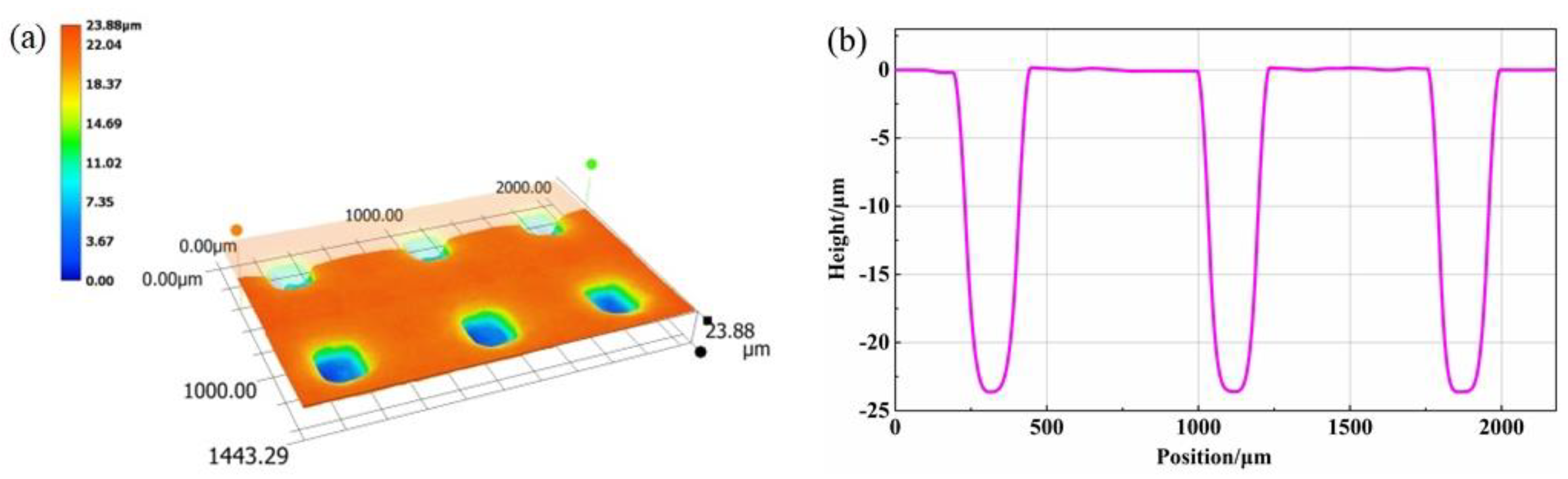
The micro-dimple arrays with good performance were generated by the optimized parameters, as shown in Figure 15. Furthermore, 3D morphology of micro-pits and the cross-sectional profile curve were obtained through optical profiling during RUREMM, as shown in Figure 16. The analysis reveals that the average width is 215.8 μm, depth is 23.6 μm, aspect ratio is 0.1094 μm, and the roughness of the smooth surface is 0.218 μm, confirming the effectiveness of the selected parameters.
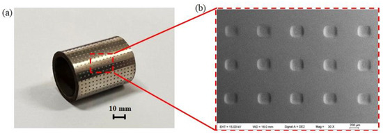
Figure 15.
The diagram of experimental results with optimized parameters. (a) Overall appearance, (b) array micro-pits.

Figure 16.
The three-dimensional diagram of array micro-pits. (a) Array micro-pits, (b) cross-sectional dimension.
7. Conclusions
In this paper, the electrolyte flow characteristics between the ultrasonic transducer with microprotrusion on its surface and a workpiece were simulated and analyzed. The surface quality, accuracy, localization, and machining stability with RUREMM were discussed and compared with EMM. The following conclusions can be drawn:
- (1)
- In RUREMM, the ultrasonic vibration can change the electrolyte flow field close to the workpiece surface to be a fluctuation in the machining gap. Therefore, the increase of electrolyte velocity, which contributes to the elimination of sludge and the diffusion of procession heat, theoretically reduces stray corrosion and machining accuracy during the machining process.
- (2)
- During RUREMM, the dispersive corrosion, localization, surface roughness, and accuracy can be improved. The results show that RUREMM is able to ensure better consistency and stability when processing micro-dimple arrays on a cylindrical surface than EMM. The average width of micro-dimples is reduced by 24.5%, the aspect ratio of dimples is increased by 108.0%, and the surface roughness of micro-dimples is decreased by 59.7%.
- (3)
- The array micro-dimples were generated using the predefined tool electrode. It was confirmed that when the stray corrosion phenomenon of micro-pits decreases, more materials are removed, and localization increases as the ultrasonic amplitude and applied pulse voltage increases. In addition, the depth of the dimples is greatly influenced by pulse voltage, and both methods have the bigger variation. The higher ultrasonic amplitude and pulse voltage will deteriorate the bottom surface quality. In addition, the micro-dimple arrays with good performance were generated using optimized ultrasonic amplitude (15 μm), pulse voltage (10 V) by RUREMM.
Author Contributions
Conceptualization, W.T., M.W. and X.X.; article identification, screening, retrieval, selection, and analysis, W.T. and M.W.; formal analysis and investigation, W.T. and T.L.; writing—original draft preparation, W.T. and M.W.; tables and figures generation, W.T. and J.W.; review and editing, W.T., M.W., T.L., J.W., W.Z. and X.X.; supervision, M.W. and X.X.; funding acquisition, M.W. All authors have read and agreed to the published version of the manuscript.
Funding
This work was supported in part by the Zhejiang Provincial Natural Science Foundation under Grant No. LY19E050007, and the National Natural Science Foundation of China under Grant No. 51975532, 51475428.
Institutional Review Board Statement
Not applicable.
Informed Consent Statement
Not applicable.
Data Availability Statement
Not applicable.
Conflicts of Interest
The authors declare that they have no conflict of interest.
References
- Lu, Y.; Deng, J.X.; Wang, R.; Wu, J.X.; Meng, Y. Tribological performance of micro textured surface machined by Nd:YAG: Laser with different incident angle. Opt. Laser Technol. 2022, 148, 107768. [Google Scholar] [CrossRef]
- He, C.S.; Yang, S.C.; Zheng, M.L. Analysis of synergistic friction reduction effect on micro-textured cemented carbide surface by laser processing. Opt. Laser Technol. 2022, 155, 108343. [Google Scholar] [CrossRef]
- Yang, K.; Feng, X.; Xia, Y.Q. A synergetic strategy based on texture and Nano-TiO2 grease to improve the tribological and insulating properties of the matrix under current-carrying friction. Tribol. Int. 2023, 183, 108379. [Google Scholar] [CrossRef]
- Walker, J.C.; Cinti, S.; Kamps, T.J.; Mitchell-Smith, J.; Clare, A.T. Influence of contact area on the sliding friction and wear behaviour of an electrochemical jet textured Al-Si alloy. Wear 2019, 426, 1336–1344. [Google Scholar] [CrossRef]
- Hao, X.Q.; Wang, L.; Lv, D.H.; Wang, Q.D.; Li, L.; He, N.; Lu, B.H. Fabrication of hierarchical structures for stable superhydrophobicity on metallic planar and cylindrical inner surfaces. J. Appl. Surf. Sci. 2015, 325, 151–159. [Google Scholar] [CrossRef]
- Zhang, K.D.; Li, H.S.; Zhang, C.; Han, Y.J.; Guo, X.H.; Liu, T.S. Effect of ion beam etching on the tribological performance of laser textured Co-Cr-Mo alloy. Opt. Laser Technol. 2023, 160, 109097. [Google Scholar] [CrossRef]
- Liu, J.; Wang, M.F.; Zhang, P.; Chen, Y.H.; Wang, S.L.; Wu, T.L.; Xie, M.R.; Wang, L.; Wang, K.H. Texture refinement and mechanical improvement in beam oscillation superimposed laser welding of TiAl-based alloy. Mater. Charact. 2022, 188, 111892. [Google Scholar] [CrossRef]
- Zheng, G.A.; Gu, Z.H.; Xu, W.X.; Li, Q.H.; Tan, Y.F.; Wang, C.Y.; Li, L. Gravitational surface vortex formation and suppression control: A review from hydrodynamic characteristics. Processes 2023, 11, 42. [Google Scholar] [CrossRef]
- Zhang, J.; Zhang, S.; Chen, G.Y.; Jia, Z.; Qu, Y.F.; Guo, Z.Y. Laser micro-texture formation mechanism based on modified heat-mass transfers and hydrodynamic models. Int. J. Mech. Sci. 2022, 230, 107528. [Google Scholar] [CrossRef]
- Ji, R.J.; Zhao, Q.Y.; Zhao, L.L.; Liu, Y.H.; Jin, H.; Wang, L.X.; Wu, L.J.; Xu, Z.J. Study on high wear resistance surface texture of electrical discharge machining based on a new water-in-oil working fluid. Tribol. Int. 2023, 180, 108218. [Google Scholar] [CrossRef]
- Gong, S.Q.; Sun, Y. Experimental study on forming consistent accuracy and tool electrode wear involved in fabricating array microelectrodes and array micro holes using electrical discharge machining. J. Mater. Process. Technol. 2022, 79, 126–141. [Google Scholar] [CrossRef]
- Chen, Z.; Wu, C.; Zhou, H.B.; Zhang, G.J.; Yan, H.Z. A high-efficiency preparation method of super wear-resistant superhydrophobic surface with hierarchical structure using wire electrical discharge machining. Surf. Coat. Technol. 2022, 444, 128673. [Google Scholar] [CrossRef]
- Sordetti, F.; Magnan, M.; Carabillo, A.; Querini, M.; Fedrizzi, L.; Lanzutti, A. Influence of the surface finishing on the wear behaviour of cemented carbides worked by Electrical Discharge Machining. Int. J. Refract. Met. Hard Mater. 2023, 113, 106196. [Google Scholar] [CrossRef]
- Liu, S.; Bao, J.; Zheng, P. A review of digital twin-driven machining: From digitization to intellectualization. J. Manuf. Syst. 2023, 67, 361–378. [Google Scholar] [CrossRef]
- Kunar, S.; Janaki, D.V. Micropatterning on stainless steel surface using electrochemical micromachining. Mater. Today Proc. 2022, 62, 6450–6454. [Google Scholar] [CrossRef]
- Maharana, H.S.; Kumar, R.; Murty, S.N.; Ramkumar, J.; Mondal, K. Surface micro-texturing of dual phase steel and copper by combining laser machining and electrochemical dissolution. J. Mater. Process. Technol. 2019, 273, 116260. [Google Scholar] [CrossRef]
- Zheng, G.A.; Shi, J.L.; Li, L.; Li, Q.H.; Gu, Z.H.; Xu, W.X.; Lu, B. Fluid-solid coupling-based vibration generation mechanism of the multiphase vortex. Processes 2023, 11, 568. [Google Scholar] [CrossRef]
- Gu, Y.H.; Zheng, G.A. Dynamic evolution characteristics of the gear meshing lubrication for vehicle transmission system. Processes 2023, 11, 561. [Google Scholar] [CrossRef]
- Zhang, Q.R.; Luo, H.P.; Liu, P.; Liu, G.X.; Zhang, Y.J. Bipolar nano-second pulse power supply for electrochemical micromachining of tungsten carbide without tool wear. Procedia CIRP 2022, 113, 471–476. [Google Scholar] [CrossRef]
- Tan, Y.F.; Ni, Y.S.; Xu, W.X.; Xie, Y.S.; Li, L.; Tan, D.P. Key technologies and development trends of the soft abrasive flow finishing method. J. Zhejiang Univ. Sci. A, 2023; in press. [Google Scholar]
- More, R.R.; Anantwar, V.V.; Anasane, S.S. Experimental investigation of electrochemical micromilling on titanium alloy (Ti6Al4V). Mater. Today Proc. 2023, 72, 1752–1757. [Google Scholar] [CrossRef]
- Egashira, K.; Okuno, Y.; Yamaguchi, K.; Ota, M. Electrochemical machining of microrods using a self-drilled hole. Procedia CIRP 2022, 113, 432–438. [Google Scholar] [CrossRef]
- Bisterov, I.; Abayzeed, S.; Speidel, A.; Magnini, M.; Zubayr, M.; Clare, A.T. Adapting ‘tool’ size using flow focusing: A new technique for electrochemical jet machining. J. Mater. Process. Technol. 2023, 311, 117807. [Google Scholar] [CrossRef]
- Wang, W.; Ming, P.M.; Zhang, X.M.; Li, X.C.; Zhang, Y.Y.; Niu, S.; Ao, S.S. Additive manufacturing of three-dimensional intricate microfeatures by electrolyte-column localized electrochemical deposition. Addit. Manuf. 2022, 50, 102582. [Google Scholar]
- Sun, Y.K.; Ling, S.Y.; Zhao, D.Y.; Liu, J.Y.; Liu, Z.A.; Song, J.L. Through-mask electrochemical micromachining of micro pillar arrays on aluminum. Surf. Coat. Technol. 2020, 401, 126277. [Google Scholar] [CrossRef]
- Patel, D.S.; Agrawal, V.; Ramkumar, J.; Jain, V.K.; Singh, G. Micro-texturing on free-form surfaces using flexible-electrode through-mask electrochemical micromachining. J. Mater. Process. Technol. 2020, 282, 116644. [Google Scholar] [CrossRef]
- Wang, M.H.; Tong, W.J.; Qiu, G.Z.; Xu, X.F.; Speidel, A.; Mitchell-Smith, J. Multiphysics study in air-shielding electrochemical micromachining. J. Manuf. Process. 2019, 43, 124–135. [Google Scholar] [CrossRef]
- Wang, M.M.; Bao, Z.Y.; Qiu, G.Z.; Xu, X.F. Fabrication of micro-dimple arrays by AS-EMM and EMM. Int. J. Adv. Manuf. Technol. 2017, 93, 787–797. [Google Scholar] [CrossRef]
- Li, L.; Tan, Y.F.; Xu, W.X.; Ni, Y.S.; Yang, J.G.; Tan, D.P. Fluid-induced transport dynamics and vibration patterns of multiphase vortex in the critical transition states. Int. J. Mech. Sci. 2023, 252, 108376. [Google Scholar] [CrossRef]
- Li, L.; Xu, W.X.; Tan, Y.F.; Yang, Y.S.; Yang, J.G.; Tan, D.P. Fluid-induced vibration evolution mechanism of multiphase free sink vortex and the multi-source vibration sensing method. Mech. Syst. Signal Process. 2023, 189, 110058. [Google Scholar] [CrossRef]
- Wang, M.H.; Zhang, Y.B.; He, Z.W.; Peng, W. Deep micro-hole fabrication in EMM on stainless steel using disk micro-tool assisted by ultrasonic vibration. J. Mater. Process. Technol. 2016, 229, 475–483. [Google Scholar] [CrossRef]
- Wu, H.Q.; Duan, W.H.; Sun, L.H.; Zeng, J.; Li, S.S.; Wang, Q.; Wu, Y.B.; Chen, Y.H. Effect of ultrasonic vibration on the machining performance and mechanism of hybrid ultrasonic vibration/plasma oxidation assisted grinding. J. Manuf. Process. 2023, 94, 466–478. [Google Scholar] [CrossRef]
- Goel, H.; Pandey, P.M. Experimental Investigations and Statistical Modeling of Ultrasonic Assisted Jet Electrochemical Micro-Drilling Process with Pulsed DC. J. Adv. Manuf. Syst. 2019, 18, 431–434. [Google Scholar] [CrossRef]
- Singh, T.; Dvivedi, A.; Shanu, A.; Dixit, P. Experimental investigations of energy channelization behavior in ultrasonic assisted electrochemical discharge machining. J. Mater. Process. Technol. 2021, 293, 117084. [Google Scholar] [CrossRef]
- Zhao, Q.Q.; Deng, Z.Q.; Yang, D.S.; Gu, X.; Zhu, Y.W. Study on multi-effect synergy mechanism of the ultrasonic compound electro-discharged and electrochemical machining and real time optimal controlling of on-line parameters. Procedia CIRP 2018, 68, 150–155. [Google Scholar] [CrossRef]
- Li, M.H.; Liu, Y.; Ling, S.Y.; Wang, K.; Jiang, Y. Theoretical and experimental study on micro ultrasonic-assisted electrochemical drilling with high speed electrode. Int. J. Adv. Manuf. Technol. 2020, 107, 815–826. [Google Scholar]
- Liu, S.; Lu, Y.; Li, J.; Shen, X.W.; Sun, X.M.; Bao, J.S. A blockchain-based interactive approach between digital twin-based manufacturing systems. Comput. Ind. Eng. 2023, 175, 108828. [Google Scholar] [CrossRef]
- Liu, S.; Lu, Y.; Shen, X.; Bao, J. A digital thread-driven distributed collaboration mechanism between digital twin manufacturing units. J. Manuf. Syst. 2023, 68, 145–159. [Google Scholar] [CrossRef]
- Tong, W.J.; He, K.L.; Wang, X.D.; Xu, X.F.; Wang, M.H. Mechanism of 6061 aluminum material erosion in USEMM. Int. J. Adv. Manuf. Technol. 2022, 118, 895–906. [Google Scholar] [CrossRef]
- Fujisawa, T.; Inaba, K.; Yamamoto, M.; Kato, D. Multiphysics Simulation of Electrochemical Machining Process for Three-Dimensional Compressor Blade. J. Fluids Eng. 2008, 130, 8. [Google Scholar] [CrossRef]
- Li, L.; Gu, Z.H.; Xu, W.X.; Tan, Y.F.; Fan, X.H.; Tan, D.P. Mixing mass transfer mechanism and dynamic control of gas-liquid-solid multiphase flow based on VOF-DEM coupling. Energy 2023, 272, 127015. [Google Scholar] [CrossRef]
- Li, L.; Lu, B.; Xu, W.X.; Gu, Z.H.; Yang, Y.S.; Tan, D.P. Mechanism of multiphase coupling transport evolution of free sink vortex. Acta Phys. Sin. 2023, 72, 034702. [Google Scholar] [CrossRef]


Disclaimer/Publisher’s Note: The statements, opinions and data contained in all publications are solely those of the individual author(s) and contributor(s) and not of MDPI and/or the editor(s). MDPI and/or the editor(s) disclaim responsibility for any injury to people or property resulting from any ideas, methods, instructions or products referred to in the content. |
© 2023 by the authors. Licensee MDPI, Basel, Switzerland. This article is an open access article distributed under the terms and conditions of the Creative Commons Attribution (CC BY) license (https://creativecommons.org/licenses/by/4.0/).