Article

Bearing Inner Ring Raceway Low-Temperature Aerosol Cooling Lubrication Grinding

1
School of Mechanical and Electrical Engineering, Lanzhou Jiaotong University, Lanzhou 730070, China
2
State Key Laboratory for Manufacturing System Engineering, Xi’an Jiaotong University, Xi’an 710054, China
*
Author to whom correspondence should be addressed.
Processes 2023, 11(5), 1546; https://doi.org/10.3390/pr11051546
Submission received: 13 April 2023 / Revised: 12 May 2023 / Accepted: 17 May 2023 / Published: 18 May 2023
(This article belongs to the Special Issue High-Performance Machining Processes: From Mechanisms to Equipment)

Abstract

:
A low-temperature aerosol cooling and lubrication grinding test bench was built to evaluate the cooling and lubrication performance of the low-temperature aerosol. The mechanism of grinding residual stresses in the inner ring raceway under the coupling effect of grinding force and grinding heat was studied, and the effects of the grinding process parameters and cooling and lubrication conditions on the distribution state of the grinding residual stresses in the surface layer of the inner ring raceway were revealed. The results showed that reducing the initial temperature of the grinding fluid could reduce the residual tensile stresses on the raceway surface. The results also showed that the low-temperature aerosol cooling lubrication method is conducive to the generation of the axial residual compressive stress of −500 MPa and tangential residual compressive stress of −300 MPa in the inner ring raceway surface layer of the bearing. Compared with the convective heat transfer coefficient, the effect of the initial temperature of the grinding fluid is smaller.

1. Introduction

During the grinding process, the grinding fluid not only reduces the temperature of the grinding area but also cleans up the grinding arc area, effectively extending the service life of the grinding wheel, ensuring the surface integrity of the workpiece, and improving the dimensional accuracy and quality of the machining.
At present, the advanced manufacturing industry pursues efficient green processing with high efficiency, high precision, high flexibility, low consumption, and low cost. Grinding is widely used for its advantages of high precision, good surface quality, and wide adaptability, especially for the processing of hard and brittle materials. Grinding is a process in which many grinding grains cut the workpiece with a negative front angle to remove the material, thus consuming a large amount of energy to grind a unit volume of material, which leads to a large grinding force and a high grinding temperature at the grinding interface, and most of the grinding heat will be transferred to the workpiece substrate, affecting the surface quality of the workpiece [1]. In order to reduce the grinding temperature during grinding, a large flow of grinding fluid is usually used as a pouring cooling lubricant, but the utilization rate of the fluid is extremely low, and the large amount of waste fluid generated is not only harmful to the environment and the human body but also increases the corresponding disposal cost, so high-speed and high-efficiency green grinding has become a hot research topic [2,3,4]. In order to protect the environment and reduce processing costs, dry grinding and low-temperature cold air micro-lubrication grinding have become some of the main methods of green grinding [5,6]. How to reduce the grinding temperature and grinding damage under the conditions of less or no coolant is an important problem to be solved in the field of green grinding.
A significant amount of research has been carried out by domestic and foreign scholars in the field of micro-lubrication [7]. Cryogenic cold air micro-lubrication (CMQL) technology involves atomizing a small amount of grinding fluid and spraying it into the grinding area through a nozzle under the impetus of high-pressure cryogenic gas, so as to provide a cooling and lubricating effect [8,9]. CMQL is a new type of cutting technology that perfectly inherits the advantages of trace lubrication technology and low-temperature cold air cutting technology, and has good characteristics in the machining process. Low-temperature trace lubrication technology reduces the cutting temperature, reduces the cutting force, and improves the lubrication effect, while also improving the surface quality of the machined surface and improving the chip form, especially in the cutting of difficult-to-machine materials, which demonstrates its excellent performance [9,10,11].
Some metals are difficult to machine with high efficiency and precision, such as tantalum [12]. The embrittlement effect of aluminum has been studied due to the adsorption of thin films [13]. The role of organic lubricant films on the integrity of the machined surface cannot be ignored and the quality of the machined surface is improved by their use [14]. The mechanism of organic film lubrication in micro-cutting has also been investigated and the Rehbinder effect further investigated experimentally [15].
The physicochemical mechanisms in ultra-precision machining are further discussed in [16]. The mechanochemical effect on the micro-cutting of AA6061 alloy is studied through characterization on the microgroove surface in [17].
The mechanochemical role of cutting fluid mainly includes the following aspects:
  • Lubricating effect: cutting fluid plays a lubricating role in the cutting process, which can reduce the friction between the material and the tool, reduce the generation and accumulation of heat, and thus reduce the wear of the tool and prolong its service life;
  • Cooling effect: cutting fluid can absorb and remove the heat generated in the cutting process and reduce the processing temperature, thus reducing the occurrence of thermal deformation and thermal cracking;
  • Cleaning effect: cutting fluid can remove chips, cutting coatings, and other impurities in the cutting process to prevent them from reattaching to the workpiece surface during machining, which affects the machining accuracy and surface quality;
  • Chemical effect: the chemical components in the cutting fluid can react with the workpiece surface to form a protective film to prevent oxidation and corrosion, thus improving the quality and machining accuracy of the workpiece surface;
  • Grinding: the abrasive particles in the cutting fluid can rub against the workpiece surface to remove surface impurities such as oxidation and burrs, thus improving the finish and precision of the machined surface.
In summary, the mechanochemical action of cutting fluid has an important influence on the stability of the cutting process, the quality of the cutting surface, and the machining efficiency.
In this paper, a bearing inner ring raceway grinding experimental platform was built to verify the grinding force and grinding heat. A bearing inner ring raceway low-temperature aerosol cooling and lubrication grinding experimental bench was built to evaluate the cooling and lubrication performance of low-temperature aerosol. The study showed that increasing the convective heat transfer coefficient and reducing the initial temperature of the grinding fluid were beneficial to the generation of residual compressive stress on the raceway surface. It is crucial to enhance the cooling and lubricating performance of the grinding fluid.

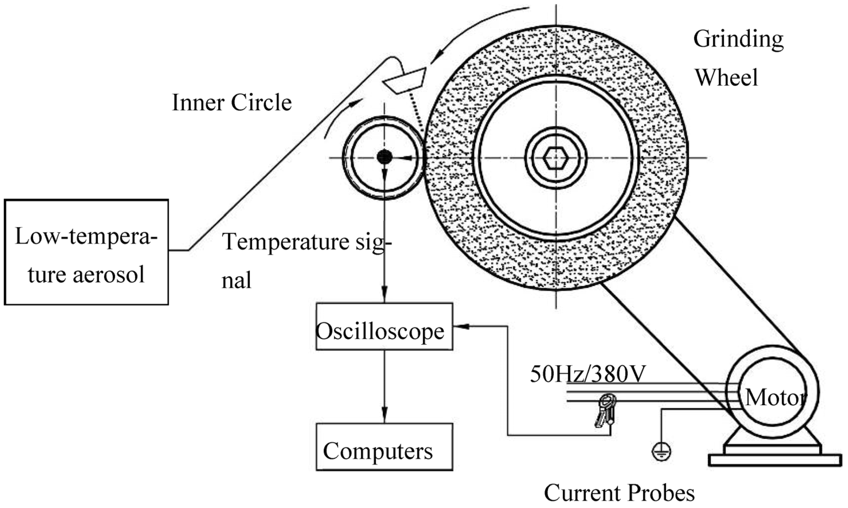
2. Bearing Inner Ring Raceway Low-Temperature Aerosol Cooling Lubrication Grinding Test Bench

The experimental bench for the grinding of bearing inner ring raceways with low-temperature aerosol cooling lubrication was built on a 3MKS1310 high-speed CNC bearing inner ring groove grinding machine. The grinding force was measured by detecting the change in the grinding wheel motor power during grinding, and the grinding temperature was measured using the thermocouple method. A schematic diagram of the bearing inner ring raceway low-temperature aerosol cooling and lubrication grinding test bench is shown in Figure 1, and the experimental site is shown in Figure 2.

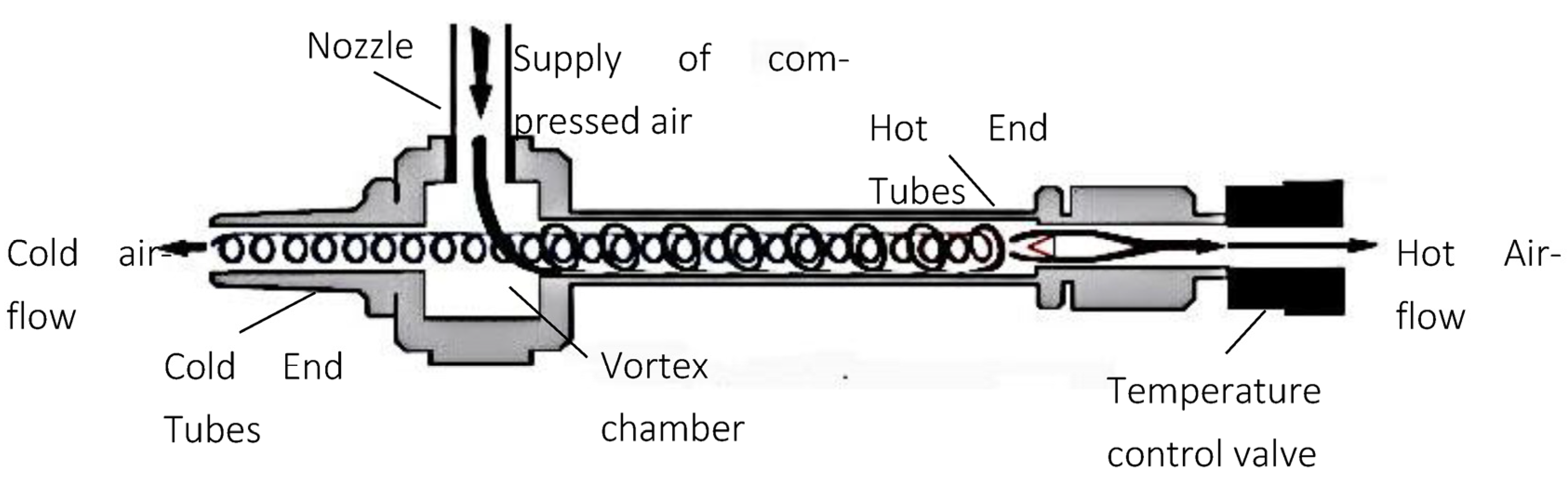
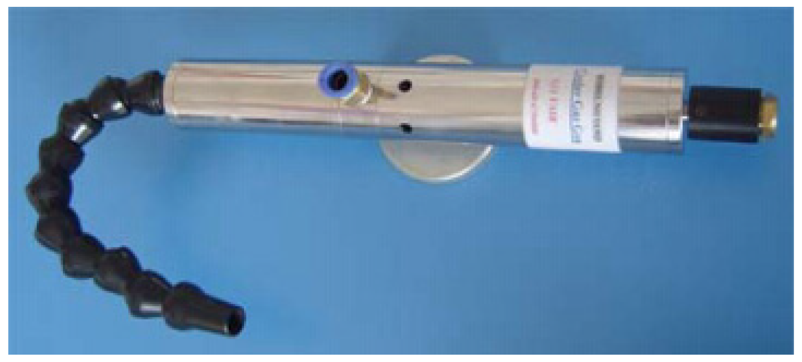
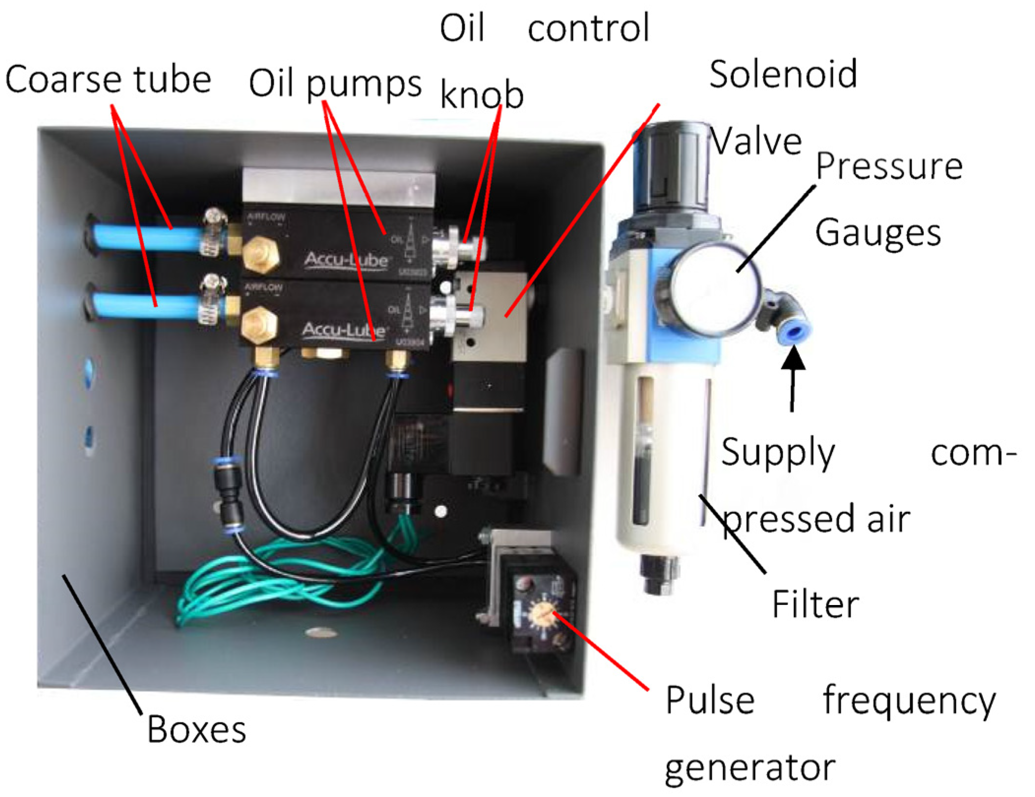
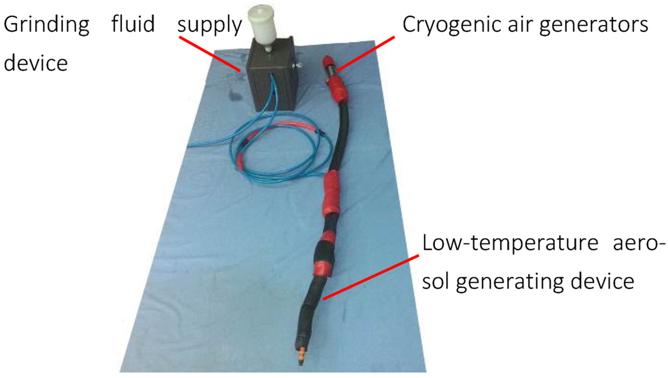
2.1. Low-Temperature Aerosol Supply System

The cryogenic aerosol fluid supply system used in this paper is shown in Figure 3.
The low-temperature aerosol supply system consists of three main parts: the first part is the low-temperature cold air generator, the second part is the grinding fluid supply device, and the third part is the low-temperature aerosol generation device. The low-temperature cold air is generated by the low-temperature cold air generator and the grinding fluid is supplied by the grinding fluid supply device; the low-temperature cold air and grinding fluid are transported to the low-temperature aerosol generator together. In the low-temperature aerosol generation device, the outer thick tube delivers the low-temperature cold air and the inner oil tube delivers the grinding fluid. In the universal joint nozzle, in front of the nozzle, the high-speed low-temperature cold air breaks up the grinding fluid into liquid droplets, thus producing a low-temperature aerosol. Each component of the low-temperature aerosol fluid supply system is described in detail below.
The low-temperature cold gas generation device mainly consists of an air compressor, air storage tank, ball valve, filter, pressure gauge, and vortex tube. The air compressor is used to generate compressed air to provide the air source for the vortex tube. The compressed air is first stored in the storage tank to ensure a stable output of compressed air. After the compressed air is filtered to remove impurities, it is fed into the vortex tube, which is used to generate low-temperature cold air.
The vortex tube converts compressed air into cold airflow and hot airflow. Adjusting the temperature control valve can control the temperature of the cold airflow, as shown in Figure 4. When the compressed air enters the vortex tube, it will be depressurized and expanded in the nozzle before entering the vortex chamber at high speed. The compressed air rotates in the hot end tube at high speed and is transformed into cold airflow and hot airflow by vortex transformation. The hot airflow rotates along the wall of the hot end tube and flows out through the outlet of the temperature control valve. The cold airflow passes through the return movement inside the hot end tube and exits through the cold end tube. Adjusting the temperature control valve will change the ratio of the hot and cold airflow, thus controlling the cold airflow temperature.
In this paper, an AiRTX stainless steel vortex tube is used, as shown in Figure 5. It can reduce the temperature of compressed air at room temperature by 28–50 °C. When the inlet pressure and temperature of the compressed air are kept constant, the temperature change of the cold air stream is only ±0.6 °C.
The grinding fluid supply device is mainly composed of an air compressor, regulator, filter, signal generator, solenoid valve, oil pump, and oil tank. The compressed air is generated by the air compressor, and after the filter removes the impurities, the compressed air is fed into the oil pump and pushes the piston to move. Using the signal generator to generate pulse signals, the two three-way solenoid valves are used to produce different actions to control the compressed airflow on and off, thus producing a pulsed airflow. When the airflow is circulated, the compressed air pushes the piston of the oil pump to move. When the airflow is disconnected, the piston returns under the action of the spring. In this way, the signal generator is used to generate a pulse signal to control the piston’s constant reciprocating movement to fill the oil tube with grinding fluid, as shown in Figure 6. The size of the grinding fluid flow is determined by both the pulse signal frequency and the oil volume control knob. Increasing the pulse signal frequency increases the number of reciprocating movements of the piston per unit of time, thus increasing the grinding fluid flow rate. Turning the oil volume control knob counterclockwise increases the piston movement stroke, thus increasing the grinding fluid flow.
The grinding fluid supply device is an improvement on the Accu-Lube micro oil supply lubrication system. The pulse frequency generator that comes with the system generates an unstable frequency, which makes it impossible to generate a pulse airflow with a stable frequency. Therefore, the signal generator and the solenoid valves are used to generate the pulse airflow and control the reciprocating motion of the piston to realize the supply of grinding fluid. A physical diagram of the Accu-Lube micro oil supply lubrication system is shown in Figure 7.
The low-temperature aerosol-generating device mainly consists of a gas pipe fitting, a gimbal nozzle, and a nozzle. The cold air and oil tubes are connected to the gimbal nozzle using a Y-type three-way air tube fitting. Inside the gimbal nozzle, the oil pipe transmits grinding fluid and outside the oil pipe transmits low-temperature cold air. In front of the nozzle, when the high-speed low-temperature cold air is in contact with the grinding fluid, due to the large relative velocity between them, the low-temperature cold air will generate a large friction force on the surface of the grinding fluid, causing the grinding fluid to scatter into droplets, thus producing a low-temperature aerosol, as shown in Figure 8.
An insulation pipe is used to wrap the location where the low-temperature cold air passes through to reduce the heat transfer between the low-temperature cold air and the outside environment, as shown in Figure 9.

2.2. Determination of Low-Temperature Aerosol Liquid Supply Parameters

Before conducting the bearing inner ring raceway cryogenic aerosol cooling lubrication grinding experiment, the cryogenic aerosol fluid supply parameters need to be determined. The low-temperature aerosol fluid supply parameters include the grinding fluid type, grinding fluid flow rate, cold airflow rate, cold air temperature, and the distance of the nozzle from the grinding arc.
Two grinding fluids are used in this paper: one is LB-2000 vegetable spray cutting oil with the specifications shown in Table 1, and the other is a water-soluble semi-synthetic cutting fluid of type PC-621F with a concentration of 5%, please refer to Table 2 for related contents.
The grinding fluid flow rate Qf was determined by both the pulse signal frequency and the oil volume control knob. Increasing the pulse signal frequency and turning the oil volume control knob counterclockwise increases the grinding fluid flow rate. Therefore, when measuring the grinding fluid flow rate, the oil volume control knob was turned counterclockwise to the maximum and the grinding fluid flow rate was controlled by the pulse signal frequency only.
The grinding fluid flow rate Q was calculated by recording the time taken to consume 50 mL of grinding fluid at different pulse signal frequencies f. The grinding fluid consumption was obtained by reading the scale on the tank and recording the time using a stopwatch. The grinding fluid flow rate was measured five times at each set of pulse signal frequencies, and the final results were averaged from the five measurements, as shown in Table 3.
The cold airflow rate Qa is controlled by a temperature control valve on the vortex tube. Turning the temperature control valve counterclockwise will reduce the temperature of the cold air and at the same time will reduce the cold airflow rate. The temperature control valve can be rotated counterclockwise up to about four turns.
Between the Y-type three-way gas fitting and the universal joint nozzle, the vortex flow meter was connected and the vortex flow meter was used to measure the cold gas flow rate Qa, as shown in Figure 10. The temperature control valve was rotated counterclockwise to a different number of turns, and in each group of rotating turns, the low-temperature cold gas flow rate was measured five times. The final result was taken as the average of the five measurements, as shown in Table 4.
The temperature control valve was rotated counterclockwise to a different number of turns and the outlet temperature of the cryogenic aerosol was measured at each set of turns Tf.
A layer of insulation pipe was wrapped around the exterior of the gas delivery tube, magnetic suction seat, and gimbal nozzle to minimize the heat transfer between the cold cryogenic gas and the outside environment. At the outlet of the cryogenic aerosol, its outlet temperature was measured using thermocouples, as shown in Figure 11. Under each group of rotating turns, the low-temperature aerosol outlet temperature was measured five times, and the final result was taken as the average of the five measurements, as shown in Table 5.

3. Bearing Inner Ring Raceway Low-Temperature Aerosol Cooling Lubrication Grinding Experiment

The bearing inner ring grinding experimental platform was built on a 3MKS1310 high-speed CNC bearing inner ring groove grinder produced by Wuxi RuiDing Machine Tool Factory. The grinding wheel drive adopts a 7.5 Kw two-pole AC motor with a direct start, the workpiece drive adopts a 1.5 Kw four-pole AC motor, and the control system adopts an AC frequency inverter infinitely adjustable speed. The machine feed and grinding wheel dressing feed are completed by servo motors. The feed of the grinding stage can be divided into five stages, which are fast leaning volume, fast tending volume, black skin volume, rough grinding volume, and fine grinding volume. The corresponding feed speeds are fast leaning speed, fast tending speed, black skin speed, rough grinding speed, and fine grinding speed, and the feed volume and feed speed can be set on the control panel.
The grinding wheel material was corundum, model A80L6V, with a grinding wheel size of 500 mm × 40 mm × 203 mm.
A low-temperature aerosol cooling lubrication grinding experiment of the bearing inner ring raceway was conducted with a 7008C bearing inner ring as the experimental object. The experiments were conducted in dry and wet grinding environments, and the grinding force and grinding temperature were measured for reference. The grinding experiment parameters are shown in Table 6 and Table 7, and the low-temperature aerosol fluid supply parameters are shown in Table 8 and Table 9.

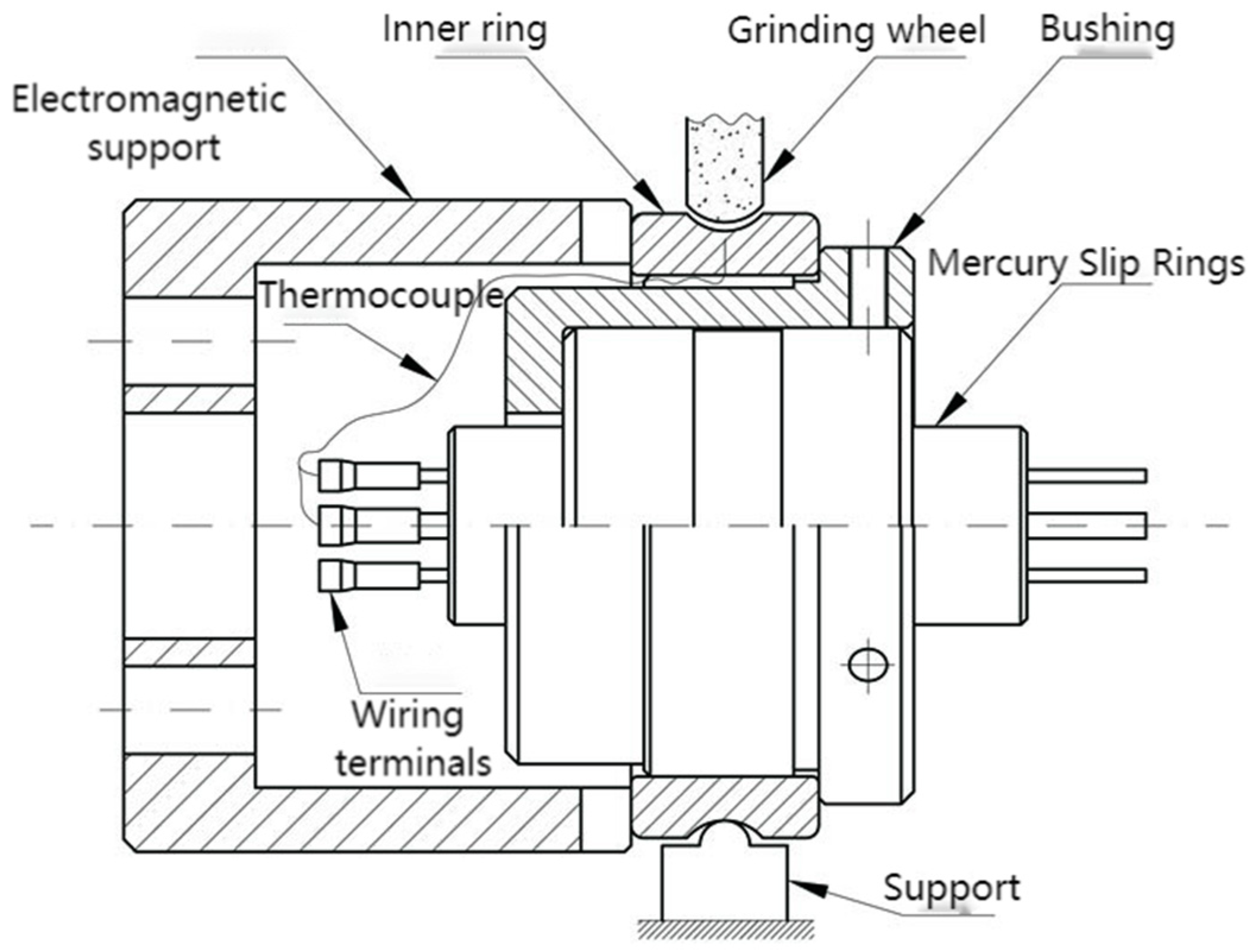
3.1. Grinding Force Test

The tangential grinding force was obtained by measuring the change in the current of the grinding wheel motor during the grinding process and obtaining the change in the output power. The Tektronix A622 current probe was used to obtain the change in the input current. This probe uses the Hall effect principle to measure AC and DC currents and output voltage signals. The frequency range was 0–100 kHz, the maximum input current was 100 A peak, the output had two grades: 10 mV/A and 100 mV/A, and the maximum conductor diameter was 11.8 mm. The voltage signal can be output by snapping the power cable into the clamp-on probe during grinding. The voltage signal was plugged into the Tektronix MSO2024 oscilloscope to obtain the change in the current. Each group of data contained 125,000 signal data, and the number of data were taken continuously as 1250, i.e., the average effective current was calculated every 0.2 s, and then, the grinding power was calculated according to the following formula:
Δ P = 3 U p h a s e Δ I p h a s e cos ϕ
where U phase = 220 V, ΔI phase is the current variation value, and cosϕ is the motor power factor, taking cosϕ = 0.8. The change in the motor power during grinding was obtained after conversion.
The tangential grinding force was calculated according to the following equation:
F t = Δ P / v s
As can be seen from Table 10, the theoretical calculation results are more consistent with the experimental data, with a maximum error of 7.17%, thus proving that the theoretical model of grinding force in this paper can be applied to the calculation of grinding force for bearing raceway grinding. Figure 12 shows the raw voltage signal. Figure 13 shows the grinding power with different grinding parameters.

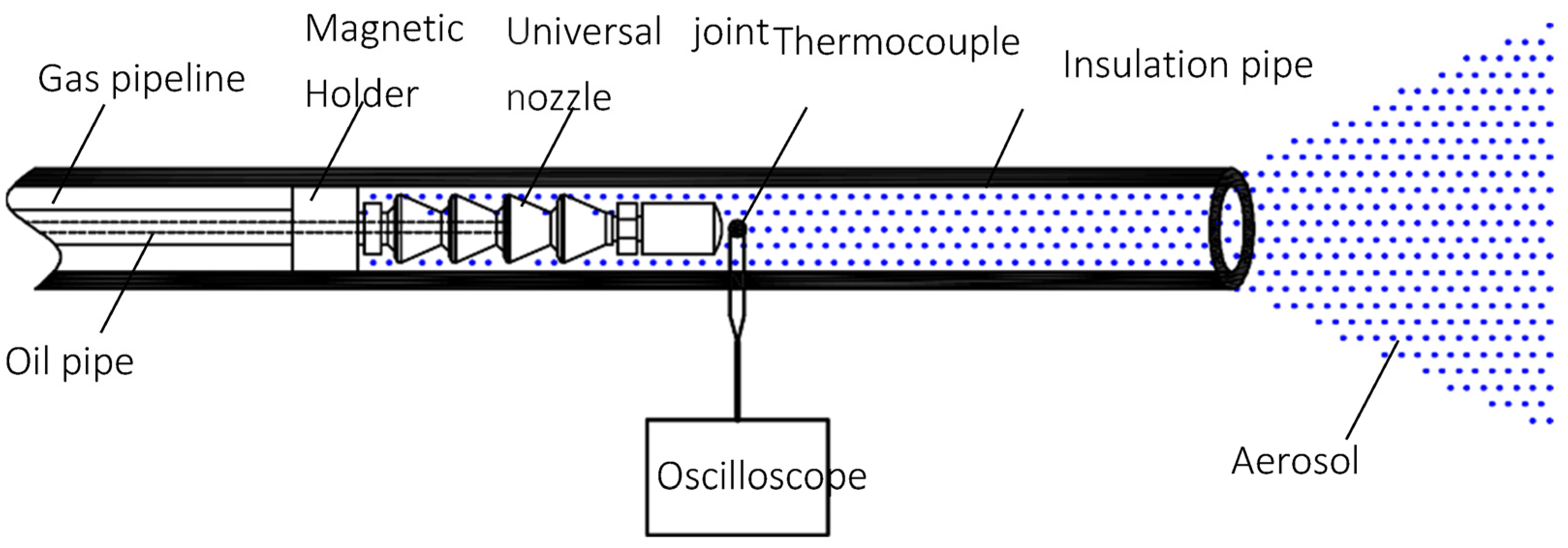
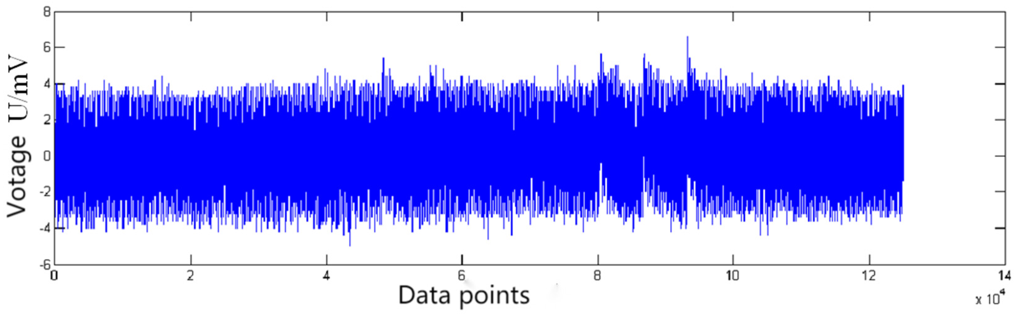
3.2. Grinding Temperature Test

There are usually two types of grinding temperature measurement, namely, the thermocouple method and the infrared thermal imaging method, of which the thermocouple method is divided into the top wire method and the pinch wire method. The conventional method is only applicable to the measurement of flat grinding temperature, and cannot be used directly for the grinding temperature of a rolling bearing inner ring. The rolling bearing is a circular workpiece, which cannot be dissected horizontally along the bearing collar axis or longitudinally along the radius of the bearing collar. Since the inner ring of the rolling bearing is different from ordinary shaft parts, its raceway surface is a concave space surface. It adopts plunge grinding, the contact area between the grinding wheel and the workpiece is large, and it is difficult for heat to dissipate. The highest temperature of the grinding arc area is generated at the position of the midpoint of the raceway, and the temperature of the grinding arc area cannot be obtained if the infrared thermography method is used. There is also the problem of how to transfer the rotating thermocouple temperature signal to the signal acquisition equipment.
At present, there is no suitable method to measure the temperature of the grinding arc of the inner race of rolling bearings. Therefore, a new grinding temperature measurement scheme needs to be designed to address the technical deficiencies that currently exist. In this section, the top wire method is used to obtain the grinding temperature signal. A blind hole is cut radially in the inner wall of the inner ring of the bearing, and the distance between the bottom of the blind hole and the surface of the bearing raceway is <0.5 mm. A copper wire is placed in the blind hole, and a multimeter is used to ensure that the top of the wire is in contact with the low end of the blind hole to form a thermocouple junction, as shown in Figure 14. A strong adhesive is used to fix the copper wire into the blind hole. Then, a strong adhesive is used to glue a wire to the inner hole wall of the collar, and a multimeter is also used to ensure that the wire is in contact with the inner hole wall of the collar. When the thermocouple junction temperature changes, the generated thermal potential signal can be derived from the copper wire and steel wire.
A mercury slip ring is used to derive the rotating thermo-potential signal. A mercury slip ring is a kind of conductive rotary joint with mercury as a fluid medium. The biggest difference with a traditional slip ring is that liquid mercury is used as a conductive medium to realize the transmission of current, power, and temperature signals between two relative rotating parts, with the advantages of reliable use, high precision, compact structure, and small size. There is also no wear and tear during rotation and it benefits from being of long life, maintenance-free, and noiseless, and has low contact resistance. The mercury slip ring’s contact resistance is less than 1 mΩ; in addition, according to the middle conductor law of thermocouples, if the middle conductor is accessed in the thermocouple circuit and the temperature at both ends of the middle conductor is the same, the access of the middle conductor has no effect on the total potential of the thermocouple circuit. The temperature at both ends of the mercury slip ring can be considered equal, and its contact resistance changes very little during the rotation, so the mercury slip ring is suitable for thermocouple signal conduction. Figure 14 shows a schematic diagram of the grinding temperature measurement. Figure 15 shows the raw thermocouple voltage signal.

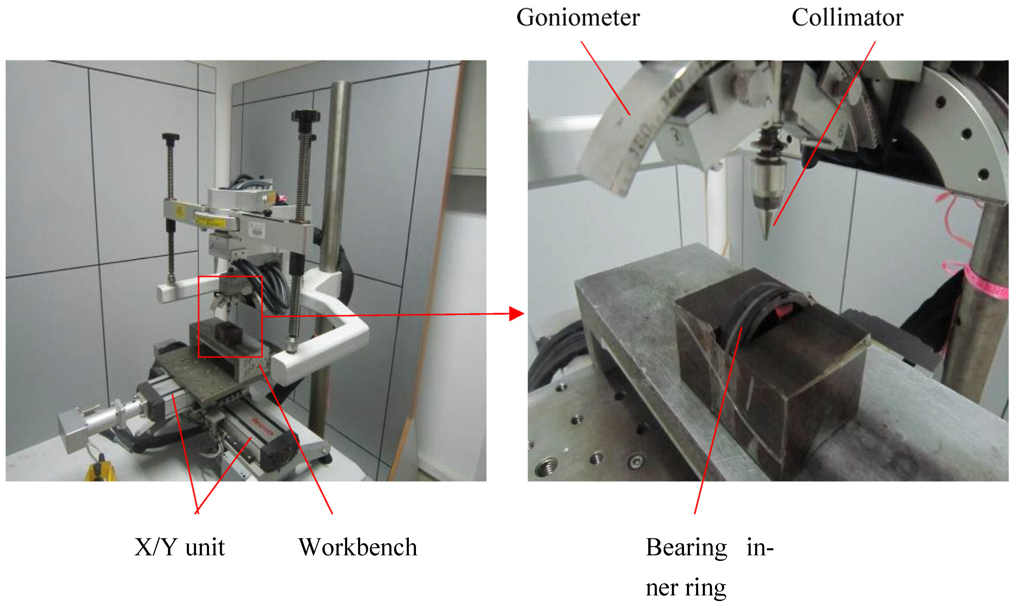
3.3. Residual Stress Measurement

The measuring instrument used in this test was an X-350A X-ray measuring instrument. Because the channel width of the 7008AC angular contact ball bearing is 7 mm, the irradiation area of the X-ray is small. In order to obtain a better diffraction peak to ensure the accuracy of the residual stress measurement, a smaller collimation tube, a larger ray tube voltage and tube current, and a longer counting time were selected.
A combination of X-ray diffraction and peeling method was used to measure the state of residual stress distribution in the inner ring raceway surface layer. Using a chemical corrosion solution to strip away the raceway surface layer by layer, the residual stress was measured using an X-ray stress analyzer. The chemical etching solution formula was 15 mL nitric acid (concentration 68%) + 5 mL hydrogen peroxide + 2 g oxalic acid, with water added to 500 mL. Ergo5881 black high-strength quick-drying adhesive was used to seal the bearing inner ring surface except for the raceway. The stripping thickness was calculated using the weighing method, and the change in the weight of the bearing inner ring before and after stripping was measured using an electronic scale (accurate to 0.01 g). An X-ray stress analyzer (XSTRESS 3000) was used to measure the residual stress, as shown in Figure 16. Before measuring the residual stress, the X-ray stress analyzer was calibrated using α-Fe powder specimens in a stress-free state. After the calibration was complete, the residual stress measurement was then performed.

4. Grinding Experimental Results and Analysis

4.1. Low-Temperature Aerosol Lubrication Performance Study

The results of the tangential grinding force measurement at different grinding fluid flow rates are shown in Figure 17. During bearing inner ring raceway grinding, the wetting area of the low-temperature air mist should cover the contact area of the grinding grains in order to obtain a better lubrication effect. As the flow rate of the grinding fluid increased, the wetting area of the low-temperature mist increased [2]. Then, the lubrication effect of the low-temperature mist was enhanced, which caused the tangential grinding force to be reduced. From Figure 17, it can be seen that when the grinding fluid flow rate was in the range of 35.29 to 136.4 mL/h, the tangential grinding force gradually decreased with the increase in the grinding fluid flow rate. This indicates that when the grinding fluid flow rate was in this range, the wetting area of the low-temperature aerosol was not sufficient to completely cover the grinding grain contact area. When the grinding fluid flow rate exceeded 136.4 mL/h, the tangential grinding force almost ceased to change with the increase in the grinding fluid flow rate. This indicates that when the grinding fluid flow rate exceeded 136.4 mL/h, the wetting area of the low-temperature aerosol completely covered the abrasive contact area. Although the wetting area of the cryogenic mist increased with the increase in the grinding fluid flow, the tangential force no longer changed due to the unchanged abrasive contact area.
The results of the tangential grinding force measurement using LB-2000 plant-based spray cutting oil to form a low-temperature aerosol at different low-temperature cold airflow rates are shown in Figure 18. Due to the influence of the air barrier in front of the grinding arc area, the low-temperature aerosol spray speed must be much higher than the grinding wheel speed to cross the air barrier and reach the grinding arc area. As the cryogenic airflow rate decreased, the cryogenic mist jet speed decreased, and the cryogenic mist passing through the air barrier to the grinding arc area decreased, resulting in a reduced wetting area. Since the wetting area could not completely cover the abrasive contact area, the tangential grinding force increased as the cold airflow rate decreased.
The tangential grinding force measurement results when the grinding fluid flow rate was 136.36 mL/h are shown in Figure 18 under different cooling lubrication conditions. From Figure 18, it can be observed that the low-temperature aerosol formed by using the LB-2000-type vegetable spray cutting oil obtained a smaller tangential grinding force than that under wet grinding conditions. The low-temperature aerosol formed using water-soluble semi-synthetic cutting fluid type PC-621F produced a tangential grinding force close to that under dry grinding conditions. This indicates that LB-2000 vegetable spray cutting oil has better lubricating performance than PC-621F water-soluble semi-synthetic cutting fluid, and the low-temperature aerosol supply parameters can be reasonably adjusted to obtain better lubricating effects than under wet grinding conditions.

4.2. Low-Temperature Aerosol Cooling Performance Study

The maximum temperature increase in the grinding arc Tmax and the tangential grinding force Ft were measured directly by the grinding experiment, and the total heat flow density qt = F vts/blc was generated in the grinding arc. Using the formula for the maximum temperature increase in the grinding arc derived by Malkin and Guo [3], the average heat flow density qwb entering the raceway of the inner ring of the bearing was calculated as shown in Equation (3).
T max = β q wb α w 1 / 2 l c 1 / 2 k w v w 1 / 2
where αw is the workpiece thermal diffusivity, kw is the workpiece thermal conductivity, β is the constant, and β = 1.06.
After obtaining the total heat flow density qt and the average heat flow density qwb into the inner race of the bearing, the heat distribution ratio εwb, εwb = qwb/qt can be obtained. Using the heat distribution ratio to study the cooling performance of low-temperature aerosol, the smaller the heat distribution ratio, the better the cooling performance.
Table 11 shows the heat distribution ratios obtained under different cooling and lubrication conditions. From Table 10, it can be observed that the heat distribution ratio was approximately 74% under the low-temperature aerosol condition. Under the wet grinding condition, the heat distribution ratio was 64.8%. This indicates that the cooling performance of the low-temperature aerosol formed using LB-2000-type vegetable spray cutting oil is not as good as that of PC-621F-type water-soluble semi-synthetic cutting fluid under wet grinding conditions.

4.3. Effect of Cooling and Lubrication Conditions on the State of Residual Stress Distribution in the Raceway Surface Layer

Under low-temperature aerosol conditions, two bearing inner rings were ground, numbered aerosol-1 and aerosol-2. Under wet grinding conditions, two bearing inner rings were ground, numbered wet grinding-1 and wet grinding-2. The lowest point of the raceway was measured along the axial direction, and the circumferential residual stress and tangential residual stress were measured, with only one measurement point per bearing inner ring. The cooling and lubrication conditions are shown in Table 12.
The bearing inner ring raceway surface residual stress distribution state under different cooling and lubrication conditions is shown in Figure 19.
From Figure 19, it can be seen that the circumferential residual compressive stress was generated in the bearing inner ring raceway surface under the low-temperature aerosol and wet grinding conditions. In the depth range of 20 μm from the raceway surface, the circumferential residual compressive stress generated under the low-temperature aerosol condition was larger than that generated under the wet grinding condition. Under wet grinding conditions, tangential residual tensile stresses were generated in the raceway surface of the inner ring of the bearing. Under low-temperature aerosol conditions, tangential residual compressive stresses were generated in the surface layer of the inner ring raceway of the aerosol-1 bearing, and tangential residual tensile stresses were generated on the surface of the inner ring raceway of the aerosol-2 bearing. Although tangential residual tensile stresses were generated on the inner ring raceway surface of the aerosol-2 bearing, the tangential residual tensile stresses generated on the inner ring raceway surface of the aerosol-2 bearing were smaller compared to those generated under wet grinding conditions. Overall, it is more favorable to generate residual compressive stresses on the inner ring raceway surface of the bearing under low-temperature aerosol conditions compared to wet grinding conditions.

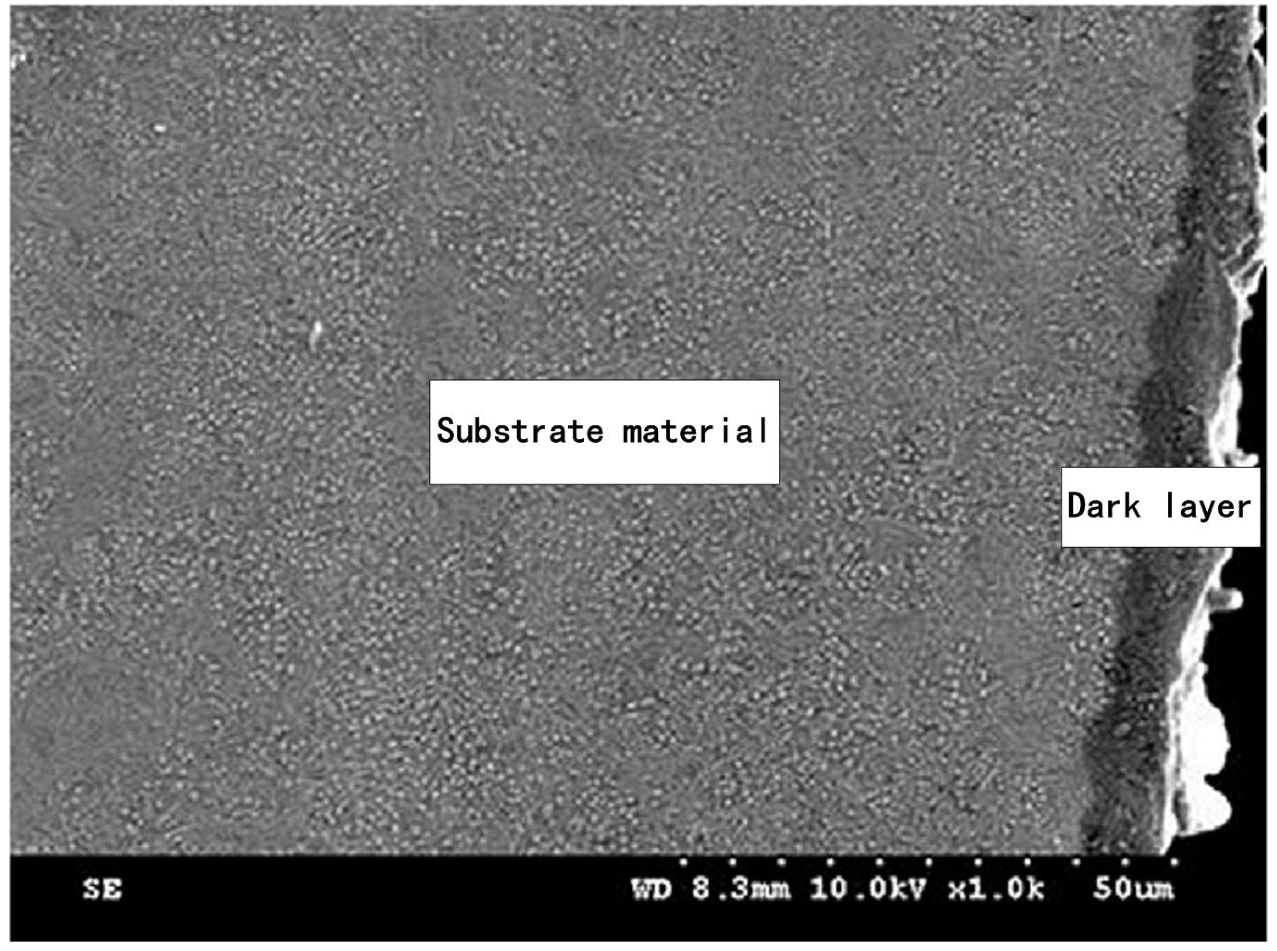
4.4. Thickness of the Layer Affected by Grinding

The thickness of the affected layer was determined by scanning electron microscopy (SEM), using an SU-8010 electron microscope. Figure 20 shows a micrograph of the affected layers. After grinding the raceway, the appearance of the affected layer obviously depends on the substrate material. In particular, a white layer was not found in the affected layer of the samples in groups 1 to 9.
From the finite element simulation, it can be observed that the maximum surface grinding temperature of the raceway of experiment No. 7 was more than 500 °C, forming a high-temperature tempering layer and producing burns on the raceway surface. Figure 21 shows the surface morphology of the bearing outer ring raceway of experiment No. 7 after grinding, and it can be seen that there is an obvious brown tempering spot on the surface as well as a burning phenomenon. Figure 20 shows the surface organization of the bearing outer ring raceway of experiment No. 7 after grinding, and it can be seen that the surface organization has obviously changed; the workpiece exhibits a dark layer, transition layer, and base material in order from the surface to the inside. The dark layer is thicker and the burn is serious.
Low-temperature cooled grinding allows the workpiece surface to acquire residual compressive stresses or reduce the magnitude of residual tensile stresses on the workpiece surface. The closer the nozzle is to the workpiece surface, the better the cooling effect. The flow rate of the cutting fluid and its coverage area should be larger than the temperature field of the grinding heat. By controlling the moving speed of the cutting fluid nozzle and the cutting fluid flow rate as well as other grinding process parameters, the control of the residual stress on the workpiece surface and improvements of the surface quality can be achieved.

4.5. Roughness Measurement

Roughness measurements were carried out in accordance with international ISO standards.
ISO 4287 is the international standard for measuring surface roughness and includes the following:
  • Definitions and symbols: defines the concepts of surface roughness, contour lines, contour surfaces and symbols;
  • Measurement length and filter: specifies the selection of measurement length and the types and parameters of filters;
  • Inspection lengths: specifies the selection and use of inspection lengths;
  • Surface parameters: lists the parameters used to describe the surface roughness, including Ra, Rz, Rq, Rt, Rp, Rv, Rsk, Rku, etc.;
  • Surface profile parameters: The parameters used to describe the surface profile are listed, including wavelength, wave height, wave number, waveform, etc.;
  • Report form: specifies the report form and content of the surface roughness measurement results.
ISO 4287 standard is applicable to surface roughness measurement of various materials, including metals, ceramics, plastics, rubber and other materials. In industrial production, ISO 4287 standard is widely used in surface quality inspection, process control, and product quality assurance.
The authors measured the roughness in both the axial and radial directions of the raceway with sampling lengths of 4 mm and 7.27 mm, respectively. Roughness testing in both directions is necessary. Due to the dynamics, the bearing raceways have different accuracy requirements in these two directions.
Figure 22 shows the roughness measurement results. Figure 23 shows the comparison of the simulated roughness and the measured roughness.

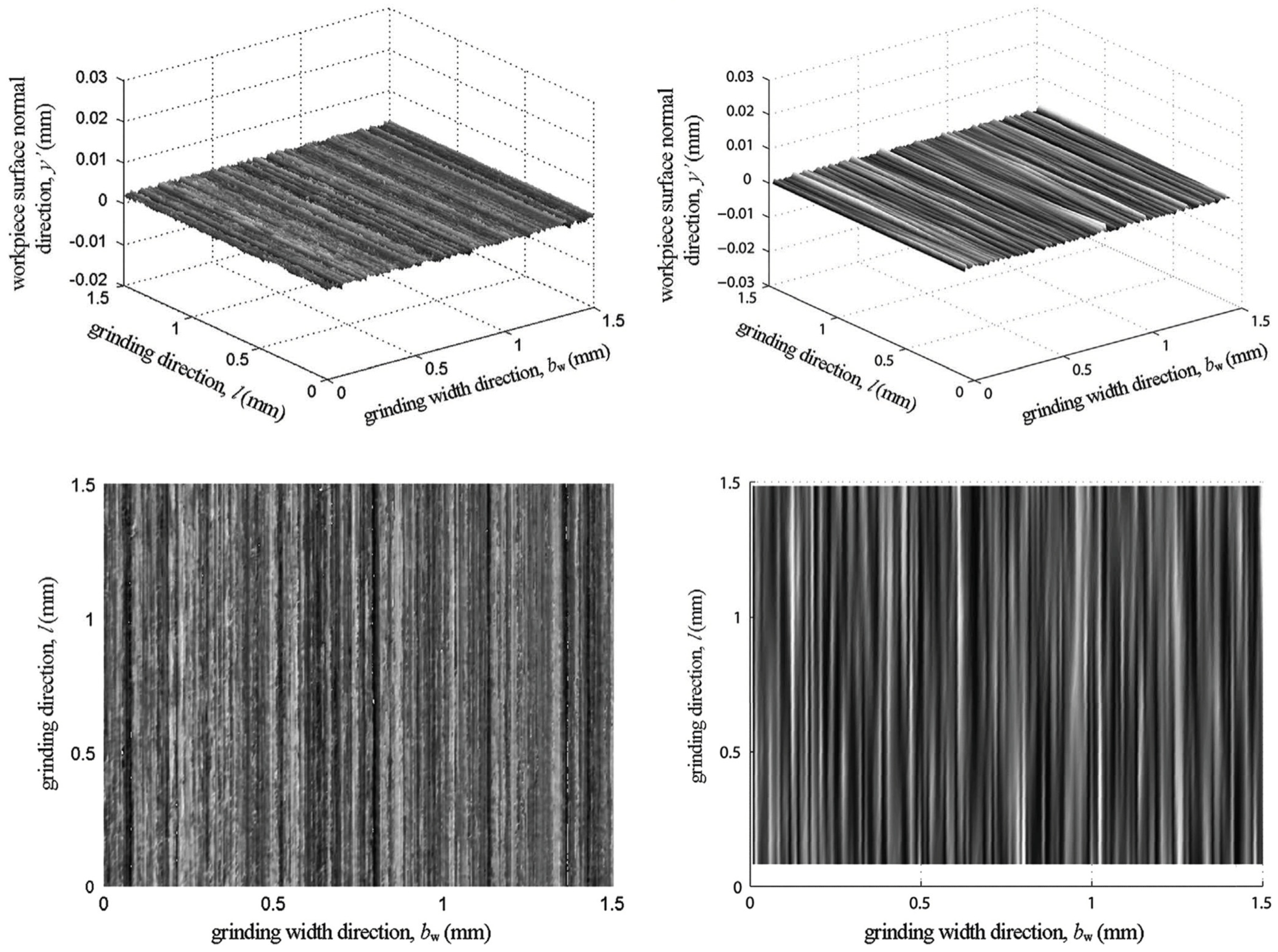
4.6. Roughness Analysis

(1)
The two-dimensional morphology of the grinding surface was simulated using contour lines, the height of each point was counted to be worth the grinding surface roughness, and the numerical relationship between the grinding parameters and the grinding surface coarse sugar content was established. The calculated results were in good agreement with the experimental data found in the literature, and when the change in the grinding parameters led to a decrease in the maximum undeformed chip thickness, the grinding surface roughness also decreased at the same time;
(2)
The dressing wear contour line was used to describe the factors such as the dressing parameters of the grinding wheel and the wear of the grinding wheel and dresser. The calculation results showed that the grinding surface profile obtained when the effects of dressing and wear were considered differed significantly from that obtained when the effects of dressing and wear were not considered. A single-factor grinding experiment with dressing guides was conducted to compare the theoretical calculation results with the experimental data, and the results showed that the prediction accuracy of the theoretical model considering the effects of dressing and wear was significantly improved, with a prediction error of less than 10%. The three-dimensional model was more accurate and obtained a grinding surface morphology close to the measured results, while the two-dimensional model was less computationally intensive and more suitable for application in production practice;
(3)
The bearing raceway grinding parameters were equated to the surface grinding process, and the influence of the grinding parameters on the raceway grinding roughness was analyzed. The results showed that within the range of the selected conventional bearing grinding parameters, the grinding roughness was influenced by the workpiece speed and increased with the increase in the workpiece speed.

5. Conclusions

(1)
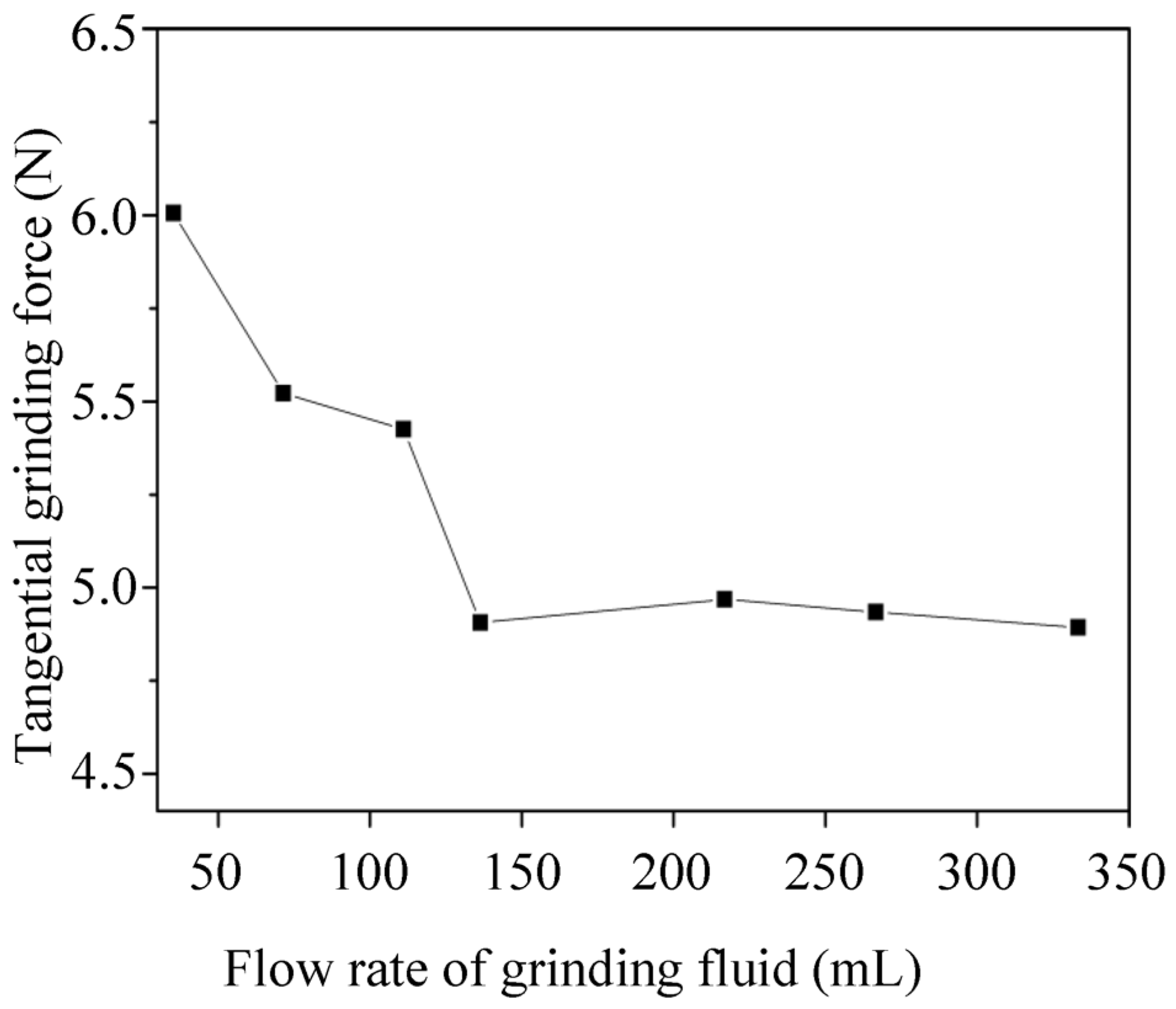
The grinding force and grinding temperature were measured using a bearing inner ring raceway low-temperature aerosol cooling lubrication grinding experiment. The experimental results showed that there was a critical value of the grinding fluid flow rate, and after this value was exceeded, the tangential grinding force no longer changed when the grinding fluid flow rate continued to increase. Decreasing the low-temperature cold airflow rate caused an increase in the tangential grinding force. Compared with PC-621F water-soluble semi-synthetic cutting fluid, LB-2000 vegetable-based aerosol cutting oil exhibited better lubrication performance;
(2)
The cooling performance and lubricating performance of the aerosol were evaluated. Compared with PC-621F type water-soluble semi-synthetic cutting fluid in a wet grinding environment, spraying LB-2000-type vegetable-based spray cutting oil can obtain a better lubrication effect, but the cooling effect is insufficient;
(3)
Under different cooling and lubricating conditions, the state of residual stress distribution on the inner ring raceway surface was measured, and the effect of cooling and lubricating conditions on the state of residual stress distribution on the inner ring raceway surface was compared and analyzed. The results showed that the low-temperature aerosol cooling lubrication method was more beneficial to the generation of residual compressive stresses in the inner ring raceway surface layer of the bearing.

Author Contributions

Z.C. designed the study. L.H. performed the research. Z.C. analyzed the data and wrote the paper. All authors have read and agreed to the published version of the manuscript.

Funding

This research was funded by the Special Funds for Guiding Local Scientific and Technological Development by the Central Government (grant number 22ZY1QA005).

Data Availability Statement

The raw/processed data required to reproduce these findings cannot be shared at this time as the data also form part of an ongoing study.

Acknowledgments

The authors wish to acknowledge Chen from Xi’an Jiaotong University for his help in interpreting the significance of the results of this study.

Conflicts of Interest

The authors declare no conflict of interest.

References

  1. Lambda, R. Finite element correction for stress relaxation in complex geometries. In Diffraction Notes; Lambda Research Inc.: Sinssinati, OH, USA, 1996; pp. 1–4. [Google Scholar]
  2. Tawakoli, T.; Hadad, M.J.; Sadeghi, M.H. Influence of oil mist parameters on minimum quantity lubrication–MQL grinding process. Int. J. Mach. Tools Manuf. 2010, 50, 521–531. [Google Scholar] [CrossRef]
  3. Malkin, S.; Guo, C. Thermal analysis of grinding. CIRP Ann.-Manuf. Technol. 2007, 56, 760–782. [Google Scholar] [CrossRef]
  4. Xi, F.; Zhou, D. Modeling Surface Roughness in the Stone Polishing Process. Int. J. Mach. Tools Manuf. 2005, 45, 365–372. [Google Scholar] [CrossRef]
  5. Chen, X.; Rowe, W.B. Analysis and Simulation of the Gring Process. Part I: Generation of the Grinding Wheel Surface. Int. J. Mach. Tools Manuf. 1996, 36, 871–882. [Google Scholar] [CrossRef]
  6. Jiang, J.L.; Ge, P.Q.; Hong, J. Study on Micro-interacting Mechanism Modeling in Grinding Process and Ground Surface Roughness Prediction. Int. J. Adv. Manuf. Technol. 2013, 67, 1035–1052. [Google Scholar] [CrossRef]
  7. Wang, D.; Ge, P.; Bi, W.; Jiang, J. Grain Trajectory and Grain Workpiece Contact Analyses for Modeling of Grinding Force and Energy Partition. Int. J. Adv. Manuf. Technol. 2014, 70, 2111–2123. [Google Scholar] [CrossRef]
  8. Malkin, S. Grinding Technology: Theory and Applications of Machining with Abrasives; Ellis Horwood: Chichester, UK, 1989. [Google Scholar]
  9. Zhou, X.; Xi, F. Modeling and Predicting Surface Roughness of the Grinding Process. Int. J. Mach. Tools Manuf. 2002, 42, 969–977. [Google Scholar] [CrossRef]
  10. Wang, G.; Wang, Y.; Xu, Z. Modeling and Analysis of the Material Removal Depth for Stone Polishing. J. Mater. Process. Technol. 2009, 209, 2453–2463. [Google Scholar] [CrossRef]
  11. Grum, J. A review of the Influence of Grinding Conditions on Resulting Residual Stresses after Induction Surface Hardening and Grinding. J. Mater. Process. Technol. 2001, 114, 212–226. [Google Scholar] [CrossRef]
  12. Davis, J.M.; Saei, M.; Mohanty, D.P.; Udupa, A.; Sugihara, T.; Chandrasekar, S. Cutting of tantalum: Why it is so difficult and what can be done about it. Int. J. Mach. Tools Manuf. 2020, 157, 103607. [Google Scholar] [CrossRef]
  13. Udupa, A.; Sugihara, T.; Viswanathan, K.; Latanision, R.M.; Chandrasekar, S. Surfacestress induced embrittlement of metals. Nano Lett. 2021, 21, 9502–9508. [Google Scholar] [CrossRef]
  14. Issahaq, M.N.; Udupa, A.; Sugihara, T.; Mohanty, D.P.; Mann, J.B.; Trumble, K.P.; Chandrasekar, S.; M’Saoubi, R. Enhancing surface quality in cutting of gummy metals using nanoscale organic films. CIRP Ann. 2022, 71, 93–96. [Google Scholar] [CrossRef]
  15. Lee, Y.J.; Wang, H. Current understanding of surface effects in microcutting. Mater. Des. 2020, 192, 108688. [Google Scholar] [CrossRef]
  16. Zhang, J.; Lee, Y.J.; Wang, H. Mechanochemical effect on the microstructure and mechanical properties in ultraprecision machining of AA6061 alloy. J. Mater. Sci. Technol. 2021, 69, 228–238. [Google Scholar] [CrossRef]
  17. Zhang, J.; Lee, Y.J.; Wang, H. Surface texture transformation in micro-cutting of AA6061-T6 with the rehbinder effect. Int. J. Precis. Eng. Manuf.-Green Technol. 2021, 8, 1151–1162. [Google Scholar] [CrossRef]
Figure 1. Schematic diagram of the bearing inner ring raceway low-temperature aerosol cooling lubrication grinding test bench.
Processes 11 01546 g001
Figure 2. Bearing inner ring raceway low-temperature aerosol cooling lubrication grinding experiment.
Processes 11 01546 g002
Figure 3. Schematic diagram of low-temperature aerosol liquid supply system. 1. Air compressor. 2. Storage tank. 3. Ball valve. 4. Filter. 5. Pressure gauge. 6. Vortex tube. 7. Air compressor. 8. Regulator. 9. Filter. 10. Signal generator. 11. Solenoid valve. 12. Oil pump. 13. Oil tank. 14. Tee joint. 15. Universal joint nozzle. 16. Nozzle.
Processes 11 01546 g003
Figure 4. Vortex tube working principle.
Processes 11 01546 g004
Figure 5. AiRTX stainless steel vortex tube.
Processes 11 01546 g005
Figure 6. Working principle of grinding fluid supply device.
Processes 11 01546 g006
Figure 7. Accu-Lube micro oil supply lubrication system.
Processes 11 01546 g007
Figure 8. Low-temperature aerosol-generating device.
Processes 11 01546 g008
Figure 9. Physical diagram of low-temperature aerosol liquid supply system.
Processes 11 01546 g009
Figure 10. Measurement of low-temperature cold airflow.
Processes 11 01546 g010
Figure 11. Determination of low-temperature aerosol outlet temperature.
Processes 11 01546 g011
Figure 12. Raw voltage signal.
Processes 11 01546 g012
Figure 13. Grinding power at different parameters.
Processes 11 01546 g013
Figure 14. Bearing inner ring raceway grinding temperature measurement scheme assembly diagram.
Processes 11 01546 g014
Figure 15. Thermocouple raw voltage signal.
Processes 11 01546 g015
Figure 16. Residual stress measurement.
Processes 11 01546 g016
Figure 17. Effect of grinding fluid flow rate on tangential force (LB-2000).
Processes 11 01546 g017
Figure 18. Effect of low-temperature cooling airflow on tangential force.
Processes 11 01546 g018
Figure 19. Effect of cooling and lubrication conditions on the state of residual stress distribution in the surface layer of the raceway.
Processes 11 01546 g019
Figure 20. Representative SEM micrograph showing the layer affected by grinding and the substrate.
Processes 11 01546 g020
Figure 21. SEM image of outer ring raceway surface of bearing No. 7.
Processes 11 01546 g021
Figure 22. Roughness measurement results.
Processes 11 01546 g022
Figure 23. Comparison between measured and simulated 3D ground surface topography.
Processes 11 01546 g023
Table 1. LB-2000 plant-based spray cutting oil.
ParametersData
Kinematic Viscosity37 mm2/s
Flash Point320 °C
Tipping Point−20 °C
Water SolubleInsoluble in water
Table 2. PC-621F Cutting Fluid Physical Properties.
ParametersData
Kinematic Viscosity51.8 mm2/s
Flash Point180 °C
Tipping Point−30 °C
Water SolubleSoluble in water
Table 3. Flow rate of grinding fluid.
Frequency (Hz)Flow Rate (mL/h)
0.535.29
171.43
1.5111.11
2136.36
3216.92
4266.67
5333.33
Table 4. Low-temperature cooling airflow.
Number of LapsFlow Rate (m3/h)
012.70
0.511.48
16.56
24.34
42.54
Table 5. Low-temperature aerosol outlet temperature.
Number of LapsTemperature (°C)
012.9
0.57.1
10.5
2−3.8
4−8.7
Note: the room temperature is 13.5 °C.
Table 6. The 3MKS1310 CNC grinding machine’s main technical parameters.
NumberTechnical ParametersValues and Descriptions
1Using the power supply50 Hz, 380 V
2Grinding wheel motorY132S2-2B3, 7.5 Kw
3Workpiece motorsY906-4B3, 1.5 Kw
4Grinding wheel sizeΦ500 × B × Φ203 mm, Bmax = 40 mm
5Grinding wheel line speed60 m/s
6Grinding wheel speed2300 r/min
7Feeding speed0–30 mm/min
Table 7. Experimental parameters of bearing inner ring raceway grinding.
Serial NumberWorkpiece Shaft Speed
nw (r/min)
Grinding Depth
ae (μm)
Feeding Speed
vf (μm/s)
112014
218016
324018
41201.56
51801.59
62401.512
712028
8180212
9240216
Table 8. The 7008C bearing inner ring raceway aerosol cooling lubrication grinding experimental parameters.
Grinding ParametersParameter Value
Grinder3MKS1310 high-speed CNC bearing inner ring groove grinding machine
Grinding wheelA80L6V
Grinding wheel diameter ds497.17~500 mm
Inner ring materialHardened bearing steel GCr15, HRC 62
Grinding wheel speed ns2300 r/min
Workpiece speed nw240 r/min
Feed rate vf16 μm/s
Grinding environmentDry grinding, wet grinding, aerosol
Wet grindingPC-621F type water-soluble semi-synthetic cutting fluid, concentration 5%
AerosolAs shown in Table 1 and Table 2
Grinding methodSmooth grinding
TrimmerSingle point diamond grain dresser
Trimming depth ad0.01 mm
Trimming speed fd0.0012 mm/r
Table 9. Parameters of low-temperature aerosol liquid supply.
ParametersParameter Value
Type of grinding fluidLB-2000 type plant-based spray cutting oil.
PC-621F type water-soluble semi-synthetic cutting fluid, concentration 5%
Grinding fluid flow35.29, 71.43, 111.11, 136.36, 216.92, 266.67, 333.33 mL/h
Low-temperature cooling airflow12.70, 11.48, 6.56, 4.34, 2.54 m3/h
Low-temperature aerosol outlet temperature12.9, 7.1, 0.5, −3.8, −8.7 °C
Nozzle distance from the grinding arc24.9 mm
Table 10. Comparison of experimental and theoretical calculation results of tangential grinding force with different parameters.
Serial NumberWorkpiece Shaft Speed
nw (r/min)
Grinding Depth
ae (μm)
Ft Experimental Value (N)Ft Theoretical Value (N)Error (%)
112011.301.217.17
218011.811.781.67
324012.322.262.62
41201.52.212.086.06
51801.53.022.923.37
62401.53.803.605.41
712023.182.986.49
818024.183.984.90
924025.104.904.00
Table 11. Heat distribution ratio under different cooling and lubrication conditions (Qf = 136.36 mL/h).
Cooling and Lubrication ConditionsQa (m3/h)Tf (°C)Ft (N)Tmax (°C)εwb
Low-temperature aerosol (LB-2000)12.7012.94.94279.60.735
2.54−8.76.84362.10.743
Wet grinding---13.55.97315.80.648
Table 12. Cooling and lubrication conditions.
Cooling and Lubrication ConditionsQa (m3/h)Qf (mL/h)Tf (°C)
Low-temperature aerosol (LB-2000)12.70136.3612.9
Wet grinding------13.5
Disclaimer/Publisher’s Note: The statements, opinions and data contained in all publications are solely those of the individual author(s) and contributor(s) and not of MDPI and/or the editor(s). MDPI and/or the editor(s) disclaim responsibility for any injury to people or property resulting from any ideas, methods, instructions or products referred to in the content.

