Article

The Optimization of Segmented Reaming Parameters and the Analysis of the Pressure Relief Effect in Impacted Coal Seams

1
Key Laboratory of Deep Coal Resource, Ministry of Education of China, China University of Mining & Technology, Xuzhou 221116, China
2
School of Mines, China University of Mining & Technology, Xuzhou 221116, China
3
School of Civil Engineering & Transportation, South China University of Technology, Guangzhou 510641, China
*
Author to whom correspondence should be addressed.
Processes 2023, 11(4), 1235; https://doi.org/10.3390/pr11041235
Submission received: 13 March 2023 / Revised: 4 April 2023 / Accepted: 12 April 2023 / Published: 17 April 2023

Abstract

:
This work focused on the insufficient or excessive pressure relief in large-diameter pressure relief by drilling. The influence of large-diameter pressure relief by drilling on the 6307 working face of the Tangkou coal mine on the roadway deformation was taken as the research background, with numerical simulations, indoor experiments, and on-site applications used. The influence of pressure relief drilling on roadway deformation was studied to propose segmented reaming pressure relief. The influences of parameters (e.g., reaming diameter, reaming depth, and borehole spacings) on the evolution characteristics of segmented reaming cracks and pressure relief were further investigated. The results showed that segmented reaming pressure relief reduced the roadway deformation and the peak elastic energy of coal in the impacted hazard area and improved the energy accumulation of the surrounding rocks of the roadway. The effect of segmented reaming pressure relief was positively correlated with the diameter and length of the reaming section; it was negatively correlated with borehole spacings. The optimized segmented reaming parameters of the 6307 working surface of Tangkou coal mine are as follows: the optimized reaming diameter of 240 mm, the reaming section depth of 15 m, and the borehole spacing of 1.6 m. Field tests proved that the optimized segmented reaming technology can improve the deformation of the surrounding rocks of the roadway and construction.

1. Introduction

As the mining of coal resources gradually develops to the deep, the impact on mines continues to increase, and the destructive effect of rock bursts also increases [1,2]. The current widely used treatment technologies mainly include deep-hole broken roof blasting, large-diameter anti-impact drilling for pressure relief, broken bottom blasting, roof hydraulic fracturing, coal seam water injection, and excavation of pressure relief chambers to prevent and control rock bursts [3,4]. The large-diameter drilling and pressure relief technology transfers high stress to the deep part of coal by constructing a series of boreholes in coal [5]. The stressed environment of the surrounding rocks of the roadway is improved to control the occurrence of impact ground pressure [6,7,8,9]. Liu et al. [10] implemented pressure relief by large-diameter drilling on the 2341 comprehensive discharge work surface of the Zhangxiaolou coal mine. Large-diameter drilling can increase the fracture density of coal and reduce the stress concentration and stress gradient of coal. Lei et al. [11] performed pressure relief by drilling into the stress concentration area of the transportation roadway of the 5244 working face of the Luxinyi mine and evaluated its safety issues. Electromagnetic radiation intensity in this area decreases after pressure relief by drilling [12]. Li et al. [13] performed pressure relief by drilling on the 8939 isolated working face of the Xinzhou Kiln mine. No serious equipment damage, roadway deformation, or casualties are caused during the mining of the working face. Therefore, pressure relief by drilling has become the main way for coal mines to deal with impacts. Researchers have used indoor experiments, numerical simulations, and other research methods to study rock burst monitoring, early warning, prevention, and control to solve rock bursts in coal mines. Zhang et al. [14] used rock mechanic tests to study the influence of density and arrangement on pressure relief by drilling. Meier et al. [15] used a three-axis test system to load shale with different drilling diameters and studied the influences of pore sizes on pressure relief. Huang et al. [16] studied the influences of drilling arrangement parameters (i.e., drilling diameter, drilling quantity, and drilling row) on the mechanical properties of the rock model through a single-axis compression test. Jia et al. [17] used the FLAC3D simulation to study the influence of pressure relief hole diameters, borehole spacings, and lengths on pressure relief. Shen et al. [18] used the ADINA finite element analysis software to study the effect of pressure relief by drilling in the compressive stress concentration area of roadway rock bursts. Song et al. [19] proposed the concept of the energy dissipation index to derive a quantitative calculation method of anti-impact drilling parameters.
However, pressure relief by drilling with a large diameter is insufficient (pressure bumping occurs after pressure relief) and excessive (excessive deformation of surrounding rocks in the stress relaxation area) [20,21,22,23,24,25]. Most studies focus on the optimization of drilling parameters, the analysis of the pressure relief effect through parameter comparison, and the alleviation of the contradiction with the control of surrounding rocks of the roadway [26,27,28]. There are few studies that have attempted to solve the above problems by innovating pressure relief by drilling [29,30,31,32].
This work carried out a laboratory test, numerical simulation, and field application based on the case of roadway deformation affected by anti-impact pressure relief by drilling with a conventional, large diameter in the haulage gate of the 6307 working face of the Tangkou coal mine. Firstly, segmented reaming technology was proposed by analyzing the influence of anti-impact pressure relief by drilling with a conventional, large diameter on the surrounding rock deformation of the roadway. Secondly, the failure characteristics of specimens were studied through the loading test of the segmented reaming of specimens, which revealed the anti-impact pressure relief mechanism of segmented reaming. Thirdly, the characteristics of surrounding rock displacement and energy release under different segmented drilling were simulated by software according to the geological conditions of the 6307 working face of the Tangkou coal mine. An optimized layout scheme of segmented pressure relief by drilling was proposed and applied on site. Compared with previous studies, this work optimized the layout parameters and anti-impact pressure relief by drilling with a conventional, large diameter and proposed pressure relief by segmented reaming. The results are important for the prevention and control of rock bursts in dangerous mines.

2. Technological Mechanism of Segmented Reaming

2.1. Pressure Relief Effect of Conventional, Large-Diameter Drilling

2.1.1. Overview of the Working Face

The 6307 working face of the Tangkou coal mine is the third mining working face in the 630# mining area of the 3# coal seam. The buried depth of the working face is 980 m, the thickness of the coal seam is 8.1–10.4 m, the average thickness is 9.44 m, the inclination angle of the coal seam is 0–7° (the average of 2°), and the inclination is 180–290°. Figure 1 shows the working face layout. The roof–floor strata of the 6307 working face are composed of relatively complete medium sandstone, siltstone, fine sandstone, and mudstone. The immediate roof is mainly mudstone, while the main roof is mainly medium sandstone.
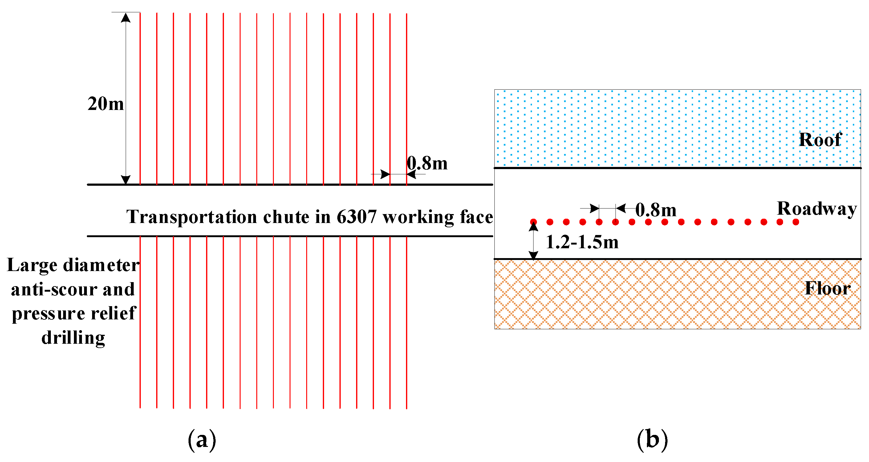
The identification results of the outburst proneness of 3# coal and roof floor in the 630# mining area and the study of geological conditions of the 6307 working face show that the 6307 working face has an outburst proneness during mining. Therefore, anti-impact drilling is pre-constructed in the area with rock burst risk in the 6307 working face. Figure 2 shows the arrangement of large-diameter boreholes in the high bump danger area according to the engineering geological conditions of the 6# mining area and the experience of drilling operations in adjacent mines.

2.1.2. Analysis of Roadway Deformation

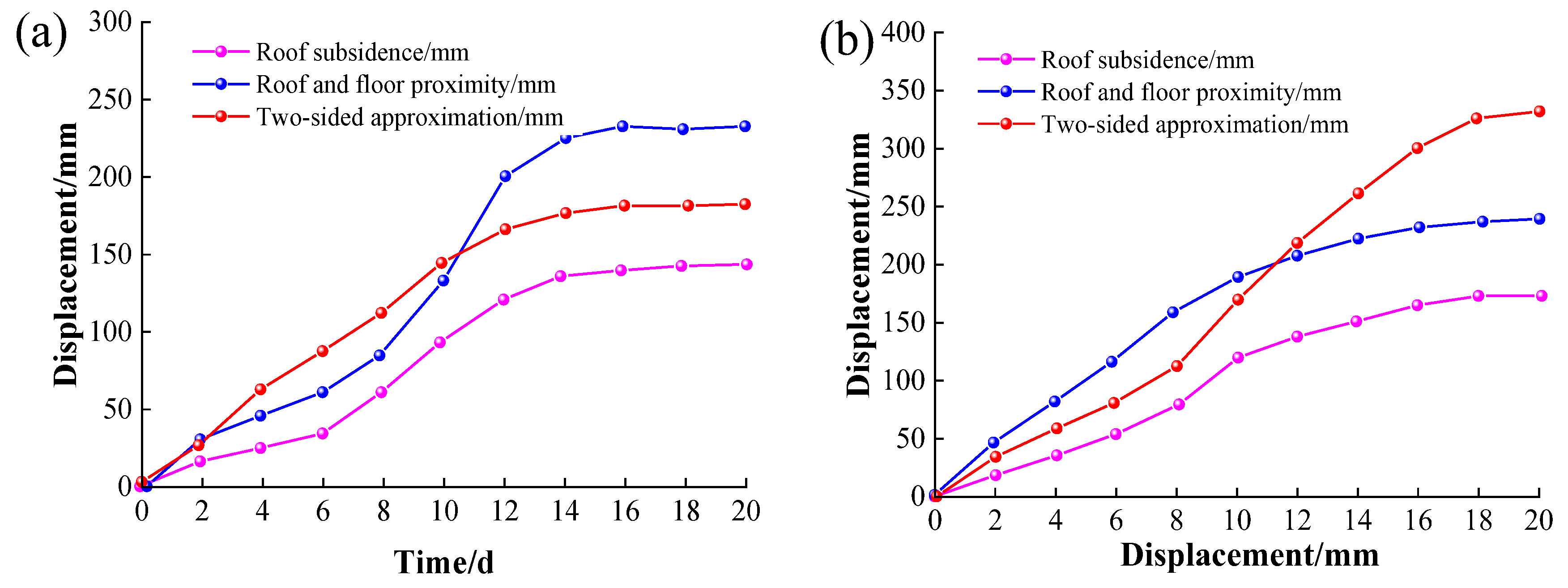
The broken bolt in the construction area caused the surrounding rock deformation in the local roadway after the implementation of anti-impact pressure relief by drilling with a conventional, large diameter on the entity coal side [33]. Figure 3 shows the monitoring data of the roadway deformation in the conventional, large-diameter drilling areas and the unconstructed area under the same supporting conditions of the haulage gate of the 6307 working face.
Figure 3 shows that the maximum displacement of the roadway roof and floor is 250 mm (Figure 3a) in the construction area of conventional, large-diameter drilling, which is similar to that in the non-construction area (Figure 3b). However, the maximum displacement of the two sides of the roadway in the two regions is quite different. The maximum displacement of the construction area is 337 mm, and that of the unconstructed area is 190 mm, with a difference of 147 mm. The sides are damaged in the area where the anti-impact pressure relief by drilling with a conventional, large diameter is implemented in the haulage gate of the 6307 working face, showing great influence of the anti-impact pressure relief by drilling.
Anchor bar stress monitoring on the two roadway sides in the stress relaxation area of the anti-impact pressure relief by drilling with a conventional large diameter shows that bolts stress increases at the initial stage of tunnel excavation and remains stable after 17 days. The final stresses of the left side bolts near and far away from the borehole and right side bolts near and far away from the borehole are 49, 94, 60, and 105 kN, respectively. The bolts that are two sides away from the impact-prevention pressure relief by drilling are broken. The final bolt stress of the two roadway sides without anti-impact pressure relief by drilling is 70 kN under the same support conditions in the working face (Figure 4).
Monitoring shows that the implementation of anti-impact pressure relief by drilling with a conventional, large diameter can alleviate bolt stress in the anti-impact pressure relief area. Meanwhile, the increased axial stress of the bolt in a similar area of the borehole indicates that the bolt stress is not coordinated. When the additional stress of pressure relief is greater than the strength of the bolt support, a bolt fracture will occur, which affects the stability of the roadway.

2.2. Pressure Relief Mechanism of Segmented Reaming Technology

The case study shows that the conventional, large-diameter anti-punch hole pressure relief uses the method of constructing large-diameter holes to reduce the energy accumulation in the impacted hazard area or change the physical properties of the coal body in the impacted hazard area so that the pressure relief areas around the hole can penetrate each other to form a weakening zone and eliminate or reduce the impacts of the surrounding rocks of the roadway [34,35]. However, conventional, large-diameter anti-scour drilling technology has problems, such as serious deformation and instability of the coal body in the roadway anchoring area, and damage to the stress environment of the roadway’s surrounding rock. Therefore, based on the shortcomings of conventional, large-diameter drilling pressure relief technology, a segmented reaming technology is proposed. Segmental reaming pressure relief uses a highly efficient cavity hollowing drill bit to use small holes in the roadway anchorage layer through reasonable reaming drilling arrangement in coal, while radially reaming in coal in the elastic zone outside the roadway anchorage layer.
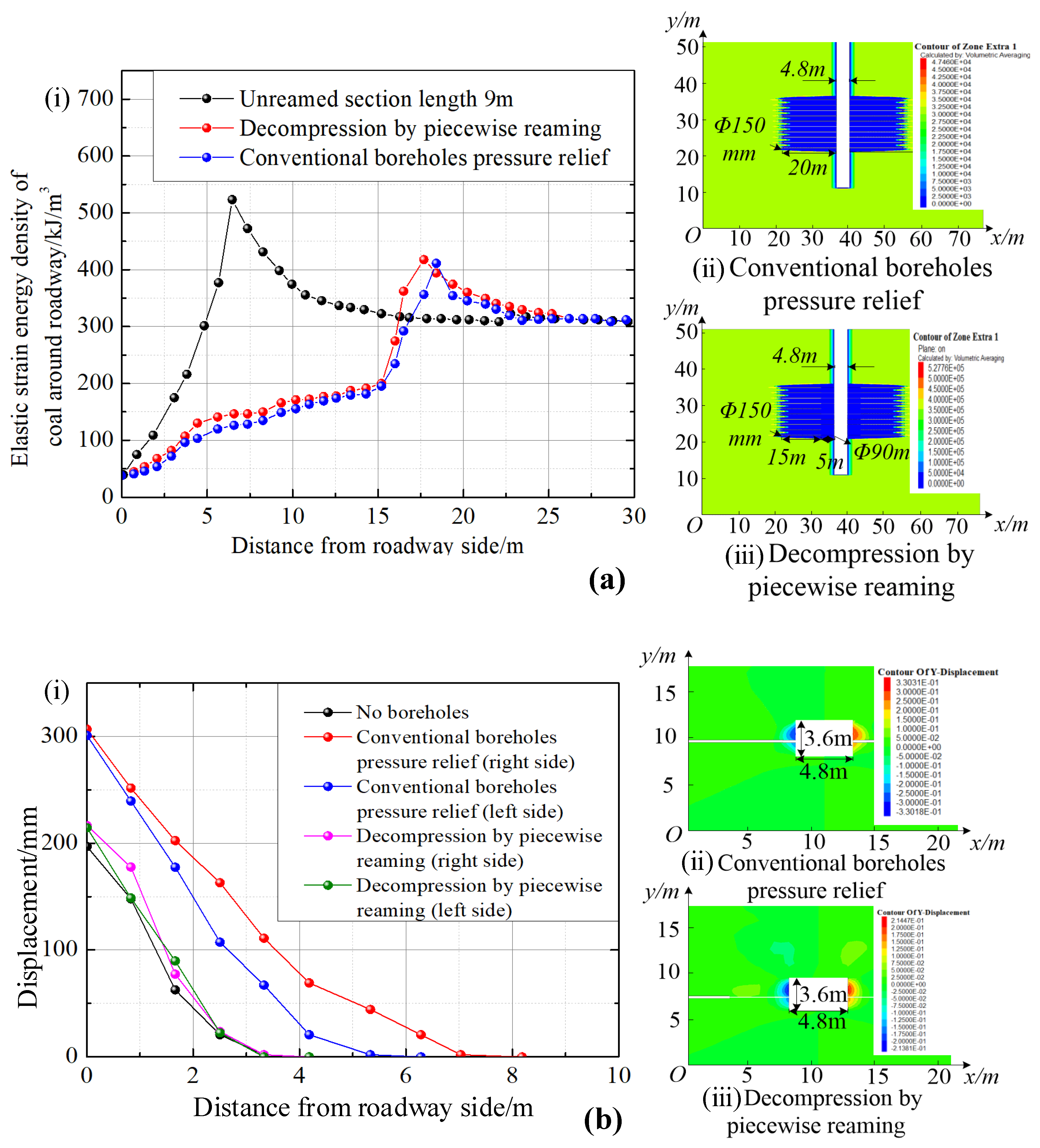
The strength criterion of the numerical model is the Mohr–Coulomb criterion. The surrounding boundary is simply supported, and the bottom is fixed. A 23 MPa even load is applied to the roof to simulate the self-gravity load of the overlying strata. The drilling depth of conventional, large-diameter pressure relief is 20 m, and the aperture is 150 mm in the simulation. The pressure relief drilling depth of segmented reaming is 20 m, with a reaming section of 15 m, and a hole diameter of 150 mm. However, the non-reaming section is 5 m, with a hole diameter of 90 mm; the other parameters are the same. Figure 5 shows the energy release and roadway deformation around the roadway under different pressure reliefs by drilling.
Figure 5a shows that the energy accumulated in the roadway is released and transferred to deep coal away from the roadway after pressure relief by segmented reaming with a conventional, large diameter. Therefore, the peak value of the coal elastic strain energy around the roadway decreases. Figure 5b shows that the displacements of the left and right sides in the roadway after pressure relief with a conventional, large diameter are 330.1 and 330.3 mm, respectively. However, the displacements of the left and right sides in the roadway after pressure relief by segmented reaming are 214.4 and 213.8 mm, respectively.
A simulation comparison shows that segmented reaming can reduce the peak value of the elastic energy of coal and the rock burst hazard of coal rocks in the impact area, and it improves the energy accumulation of the surrounding rocks of the roadway. Meanwhile, the influence of the impact-prevention pressure relief borehole on the roadway deformation is reduced due to the small diameter of the non-reaming section of pressure relief by subsection reaming and the small boundary of the drilling affected areas in the anchorage layer of the surrounding rocks of the roadway. Figure 6 shows the mechanism of pressure relief by segmented reaming.

3. Test Room Study of Segmented Reaming Pressure Relief

The indoor test shows the mechanism and effect factors of segmented reaming pressure relief by studying the influence of segmented reaming on specimen strength and the surrounding crack propagation.

3.1. Test Procedure

3.1.1. Preparation of Test Materials

The mechanical properties of coal rock specimens were affected by the geological structure or processing process; therefore, rock-like specimens were used. The material had a small porosity and high strength after casting and water hardening with mold plasters, which were used to simulate coal rocks. Therefore, the mechanics of materials are similar to that of coal rocks in engineering according to the similarity theorem. The orthogonal design determined the material distribution ratio of each model specimen (water/gypsum = 5:9), and the uniaxial compressive strength of similar materials was 17.0 MPa, which is similar to that of 3# coal. Then, cuboid specimens (50 × 50 × 100 mm) were made according to the relevant standards [36].

3.1.2. Test Scheme Design

The specimen was loaded at a speed of 0.025 mm/min until the bearing capacity was lost. The diameter and depth of the reaming hole and the borehole spacing were studied experimentally. The influence of reaming by drilling on specimens’ strength and the surrounding crack propagation under uniaxial compression was analyzed. The fixed-variable method was used to study the influence of a single factor on the effect of segmented reaming pressure relief. The diameter of the fixed drilling section was 25 mm, and the diameters of the reaming section were 3, 6, and 9 mm, respectively, to study the influences of reaming section diameters on pressure relief. The diameter of the fixed reaming section was 9 mm, and the depths of the reaming section were 15, 25, and 35 mm, respectively, to study the influence of the reaming section depth on pressure relief. The depth of the fixed reaming section was 25 mm; the diameter was 6 mm; and the borehole spacings were 15, 22.5, and 30 mm, respectively. Table 1 presents the test scheme.

3.2. Test Results and Analysis

3.2.1. Test Scheme 1: Different Reaming Diameters

(1)
Analysis of pressure relief effect
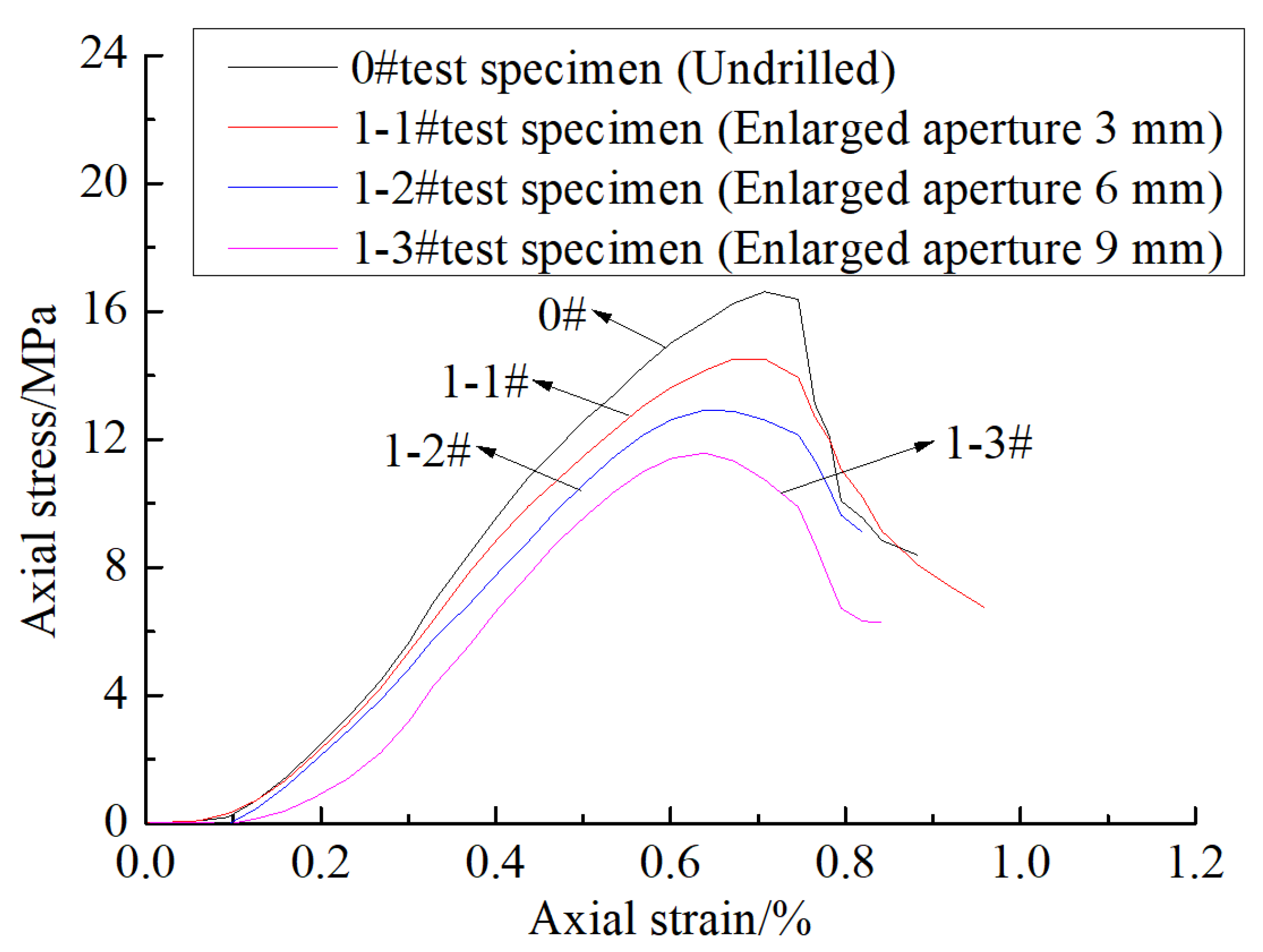
Figure 7 shows the uniaxial stress–strain curves of specimens with different reaming diameters. The uniaxial compressive strength of complete specimens reaches 17.0 MPa. The strength of the specimens is reduced to 15.5, 12.8, and 11.7 MPa, respectively, after reaming with different diameters (3, 6, and 9 mm); the corresponding decreasing amplitudes are 8.8, 24.7, and 31.2%, respectively. The larger the reaming diameter, the lower the strength of the specimens, and the greater the released pressure by drilling. Therefore, the pressure relief effect of segmented reaming becomes obvious with the increased reaming section diameter.
(2)
Failure form and crack development of specimens
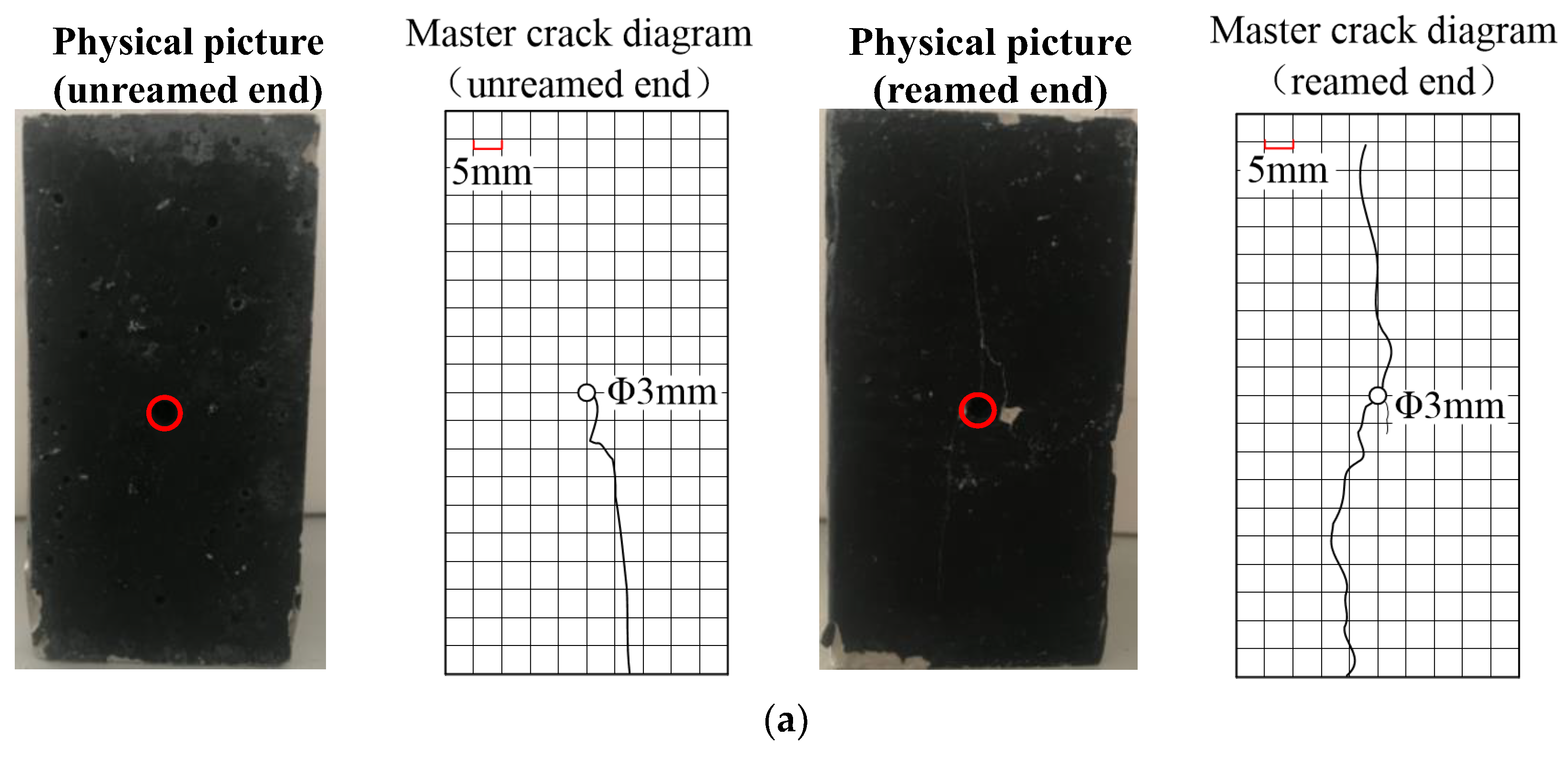
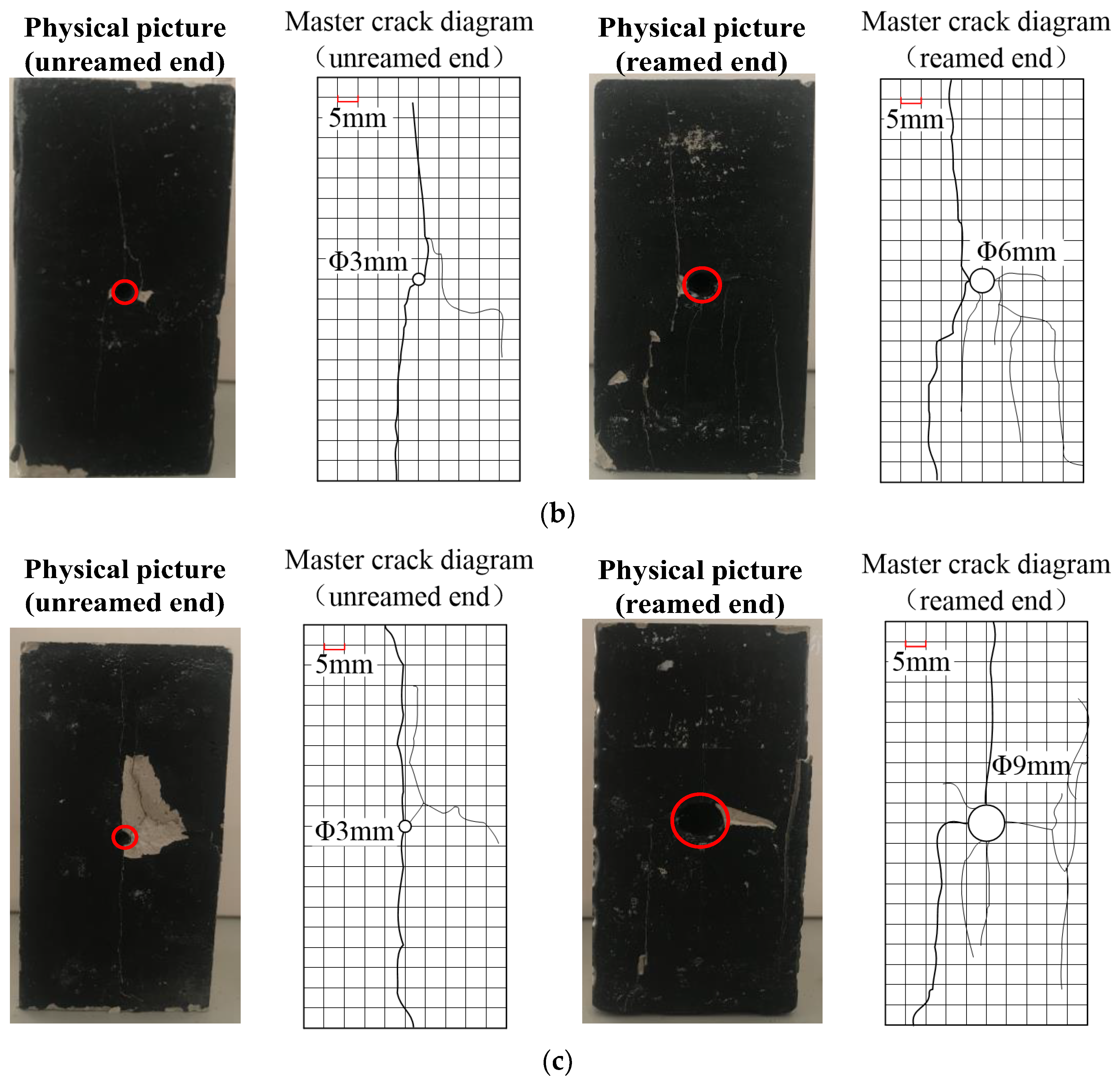
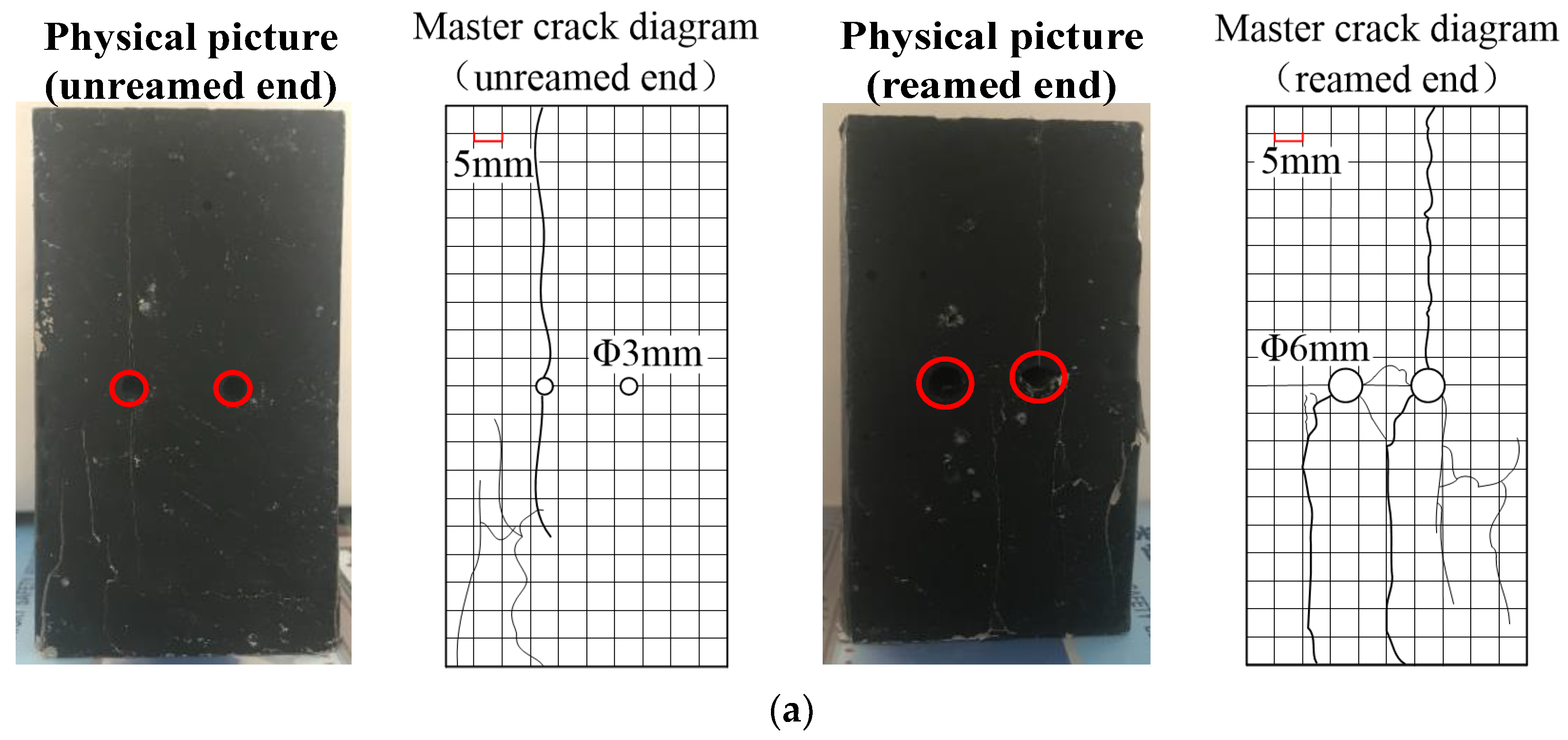
Figure 8 shows the macro fracture of specimens with different reaming diameters. The macroscopic deformation and failure modes of specimens under uniaxial compression include hole wall collapse, crack propagation, and surface-stripped damage. Borehole specimens with different borehole diameters produce cracks at the center of the reaming end hole, and they extend approximately along the axial stress direction to the upper and lower ends, which forms the main crack through the borehole.
Then, the internal cracks of specimens expand and are destroyed with increased stress. Figure 8a shows that the unexpanded specimen produces a main crack through the borehole during the failure process, and surface-stripped damage occurs. Figure 8b shows that the crack width is small at the unexpanded end of specimens with a diameter of 6 mm, and a main crack is generated. However, crack propagation at the reaming end is clear. The width increases and the tensile crack generated around the hole is small. Figure 8c presents the macro fracture of specimens with a diameter of 9 mm, and a main crack running through the borehole is generated at the unexpanded end. The tensile cracks are generated on both sides of the hole, and the propagation direction is similar to the axial loading direction.
The comparison of crack development around the two ends of the borehole with different borehole diameters is as follows: (1) The number and width of cracks around the unexpanded end of specimens with different reaming diameters change little, and the damage degree is similar. (2) The number of cracks around the hole of specimens with a diameter of 9 mm at the reaming end is more than that of specimens without reaming or reamed with a diameter of 6 mm. The failure strength of specimens with a large hole diameter is reduced, but it is higher than that of specimens with a small hole diameter. Therefore, the borehole diameter of specimens is proportional to their strain energy release and pressure relief effect.

3.2.2. Test Scheme 2: Different Reaming Depth

(1)
Pressure relief effect analysis
Figure 9 shows the uniaxial/axial stress–strain curves of specimens with different reaming depths (the diameters of reaming and non-reaming sections are 9 and 3 mm, respectively). The uniaxial compressive strength of the complete specimen is 17.0 MPa. When the reaming depths are 15, 25, and 35 mm, the strengths of specimens are 14.6, 13.5, and 13.0 MPa, respectively; the corresponding decreasing amplitudes are 14.1, 20.6, and 23.5%, respectively. If the reaming depth is large, specimen strength is reduced, and the pressure relief amplitude of the borehole increases. Therefore, the pressure relief effect of segmented reaming is proportional to the reaming section length of the borehole.
(2)
Failure mode and crack development of specimens
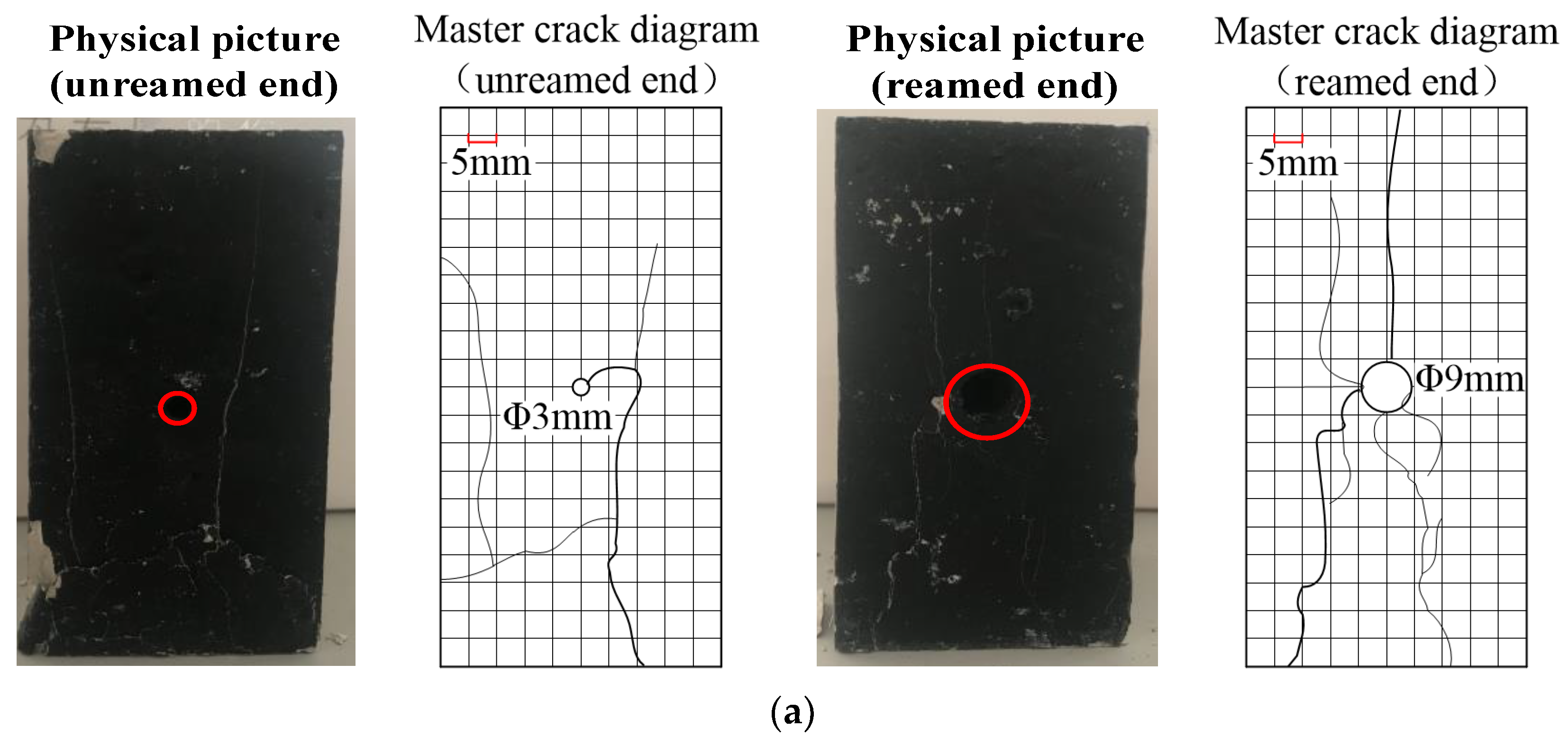
Figure 10 shows the macro fracture of specimens with different reaming depths (the diameters of reaming and non-reaming sections are 9 and 3 mm, respectively). Specimens with different reaming depths produce tensile cracks at the reaming end hole center under stress compression. Then, it expands toward the upper/lower ends along axial stress and forms the main crack through the borehole.
The internal crack of specimens expands with increased axial stress. The surface at both ends of the borehole with a reaming depth of 15 mm is peeled off during the failure process. The crack number at the reaming end is more than that at the non-reaming end (Figure 10a). If the reaming depth of the borehole is 25 mm (Figure 10b), the main crack through the borehole is generated at the non-reaming end. However, tensile cracks are generated around the borehole at the reaming end in addition to the main crack, and the growth direction is similar to the axial loading direction.
The number of cracks at the reaming end of specimens is more than that at the non-reaming end during the failure process of 35 mm reaming depth (Figure 10c). There are tensile cracks around both ends of the borehole. The crack propagation texture of specimens with a 35 mm reaming depth is clearer and wider than that with a smaller depth. Therefore, the reaming depth can significantly affect the failure of specimens.
The side failure (Figure 11) and the number of cracks of specimens drilling with different reaming depth show the following: (1) The reaming depth can affect the crack location and propagation width on the drilling side. (2) The side crack appears near reaming, and the position is first damaged; therefore, the reaming depth can affect the failure of specimens.

3.2.3. Test Scheme 3: Different Borehole Spacings

(1)
Analysis of pressure relief effect
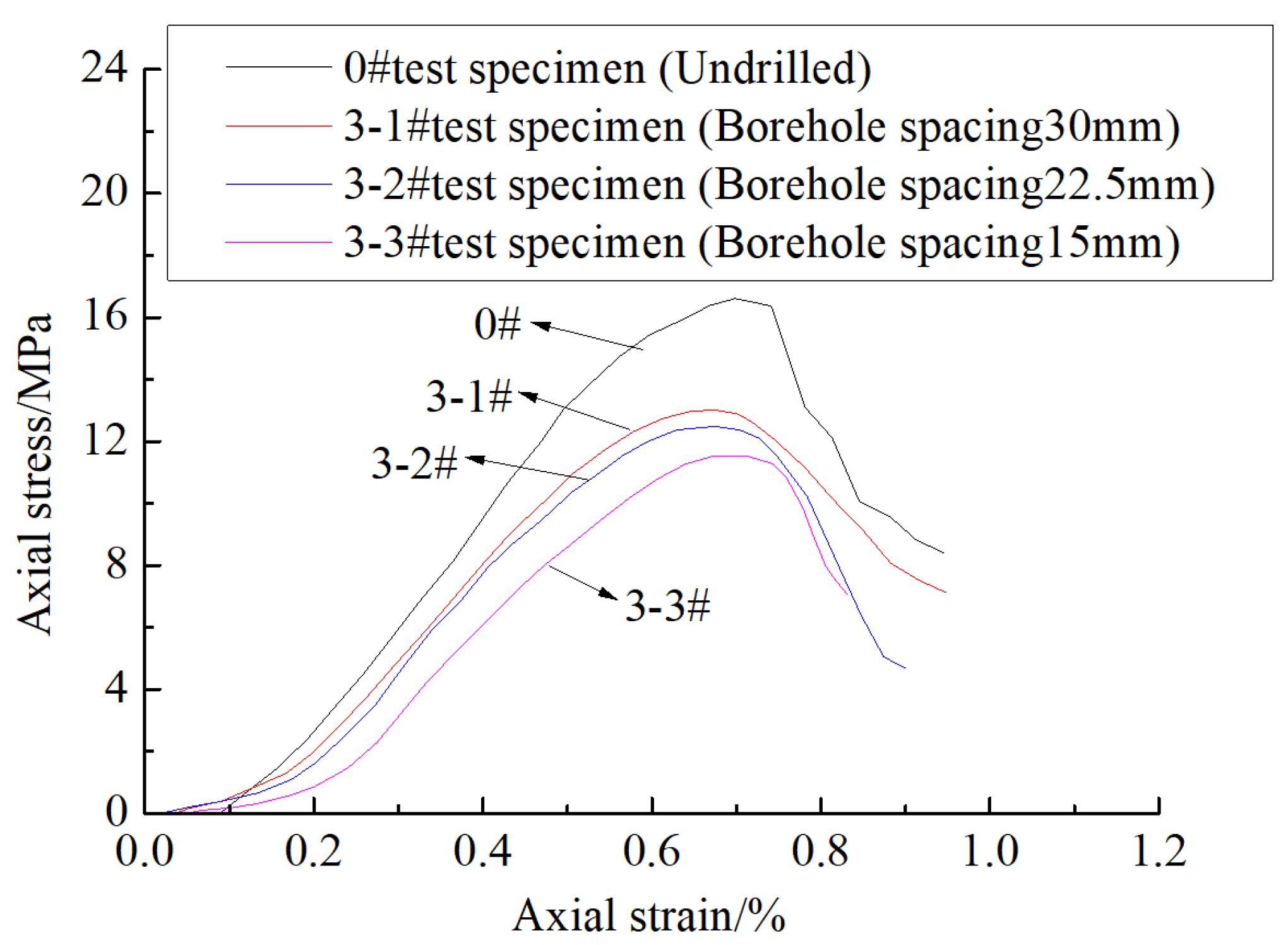
Figure 12 shows the uniaxial stress–strain curves of specimens with different borehole spacings. The uniaxial compressive strength of the complete specimens is 17.0 MPa. It reduced to 11.7, 12.5, and 13.1 MPa (by 31.2, 26.5, and 22.9%), respectively, after drilling at different depth (15, 22.5, and 30 mm). The specimen’s strength increases with the increased borehole spacing. Therefore, the borehole spacing of segmented reaming is inversely proportional to the pressure relief amplitude and effect.
(2)
Failure mode and crack development of specimens
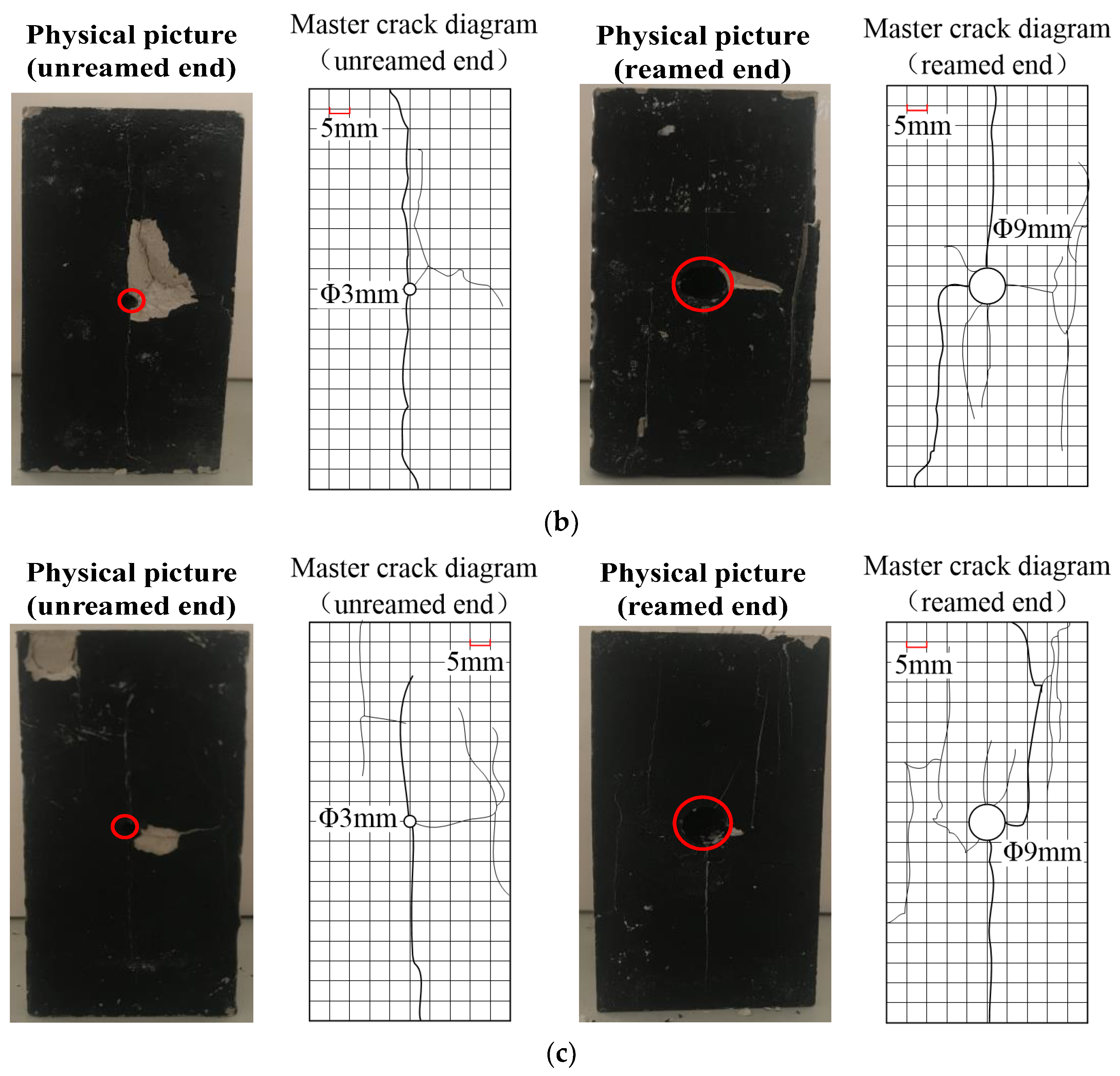
Figure 13 shows the macro fracture of specimens with different borehole spacings: The diameters of the borehole and reaming are 3 and 6 mm, respectively, with a reaming depth of 25 mm. The macro fractures at both ends of specimens are characterized by hole wall collapse, crack propagation, and surface spalling failure under uniaxial compression. The crack development degree at the reaming end is greater than that at the non-reaming end.
The failure modes of specimens with different borehole spacings are divided into three categories: (1) Pass-through failure: The borehole spacing is 15 mm, and the secondary cracks at both ends of the drilling extend through surrounding rocks between the two holes, which reduces specimen strength. (2) Independent pass-through transitional failure: Two holes with a borehole spacing of 22.5 mm have no penetration at the non-reaming end, and they expand and deflect to the middle of the specimens at the enlarged end. The surface spalling failure of the rock masses between the holes occurs due to stress concentration, and the main control cracks of the two holes at the reaming end are penetrated. (3) Independent failure: The large borehole spacing (30 mm) at both ends of the specimens weakens their interaction and enhances their independence, which makes the stress state similar to that of two separate boreholes. The drilling position is close to the specimen edge, which results in large edge damage with surface spalling. However, the cracks around the boreholes at both ends are not penetrated, indicating that the borehole spacing can affect strength at both ends of the borehole. The interaction between two holes of the reaming specimens is obvious, and cracks between holes are relatively more developed than the non-reaming end.
The research shows that the asymmetric development of cracks at both ends of the specimens after reaming is the fundamental mechanism of segmented reaming pressure relief. The diameter and depth of the reaming hole and the borehole spacing affect the crack development at both ends of the reaming specimens. Therefore, failure modes of samples with different parameters show that the diameter and depth of reaming and borehole spacing can affect the pressure relief effect of segmented reaming. The increased reaming diameter leads to asymmetric crack propagation at both ends of the specimens and a good, coordinated control effect of the pressure relief and the surrounding rocks of the roadway. The changes in the reaming depth and borehole spacings affect the crack development at both ends of the borehole.

4. Research on the Layout Optimization of Segmented Reaming Parameters

Reaming parameters affect the crack development at both ends of the reaming specimens. Meanwhile, the diameter and depth of reaming or borehole spacings affect the development and penetration of cracks around the boreholes at the non-reaming end. A reasonable reaming diameter, reaming depth, and borehole spacings can have an anti-impact pressure relief and reduce the deformation of the roadway’s surrounding rocks during segmented reaming pressure relief of roadways with impact risks. Therefore, the FLAC3D numerical simulation is used to optimize the arrangement of segmented reaming parameters considering the actual situation of the haulage gate in the 6307 working face.

4.1. Simulation Design of Segmented Reaming Parameter Arrangement

Three numerical simulation schemes were designed for different reaming section diameters, reaming depth, and borehole spacing. The energy release and displacement variation differences between the two sides of the roadway under different schemes were compared, and the pressure relief effects of different segmented reaming parameters were obtained. Table 2 shows the simulation scheme.

4.2. Simulation Results and Analysis

4.2.1. Simulation Scheme 1: Simulation Results Analysis

(1)
Energy release characteristics of the surrounding rocks of the roadway
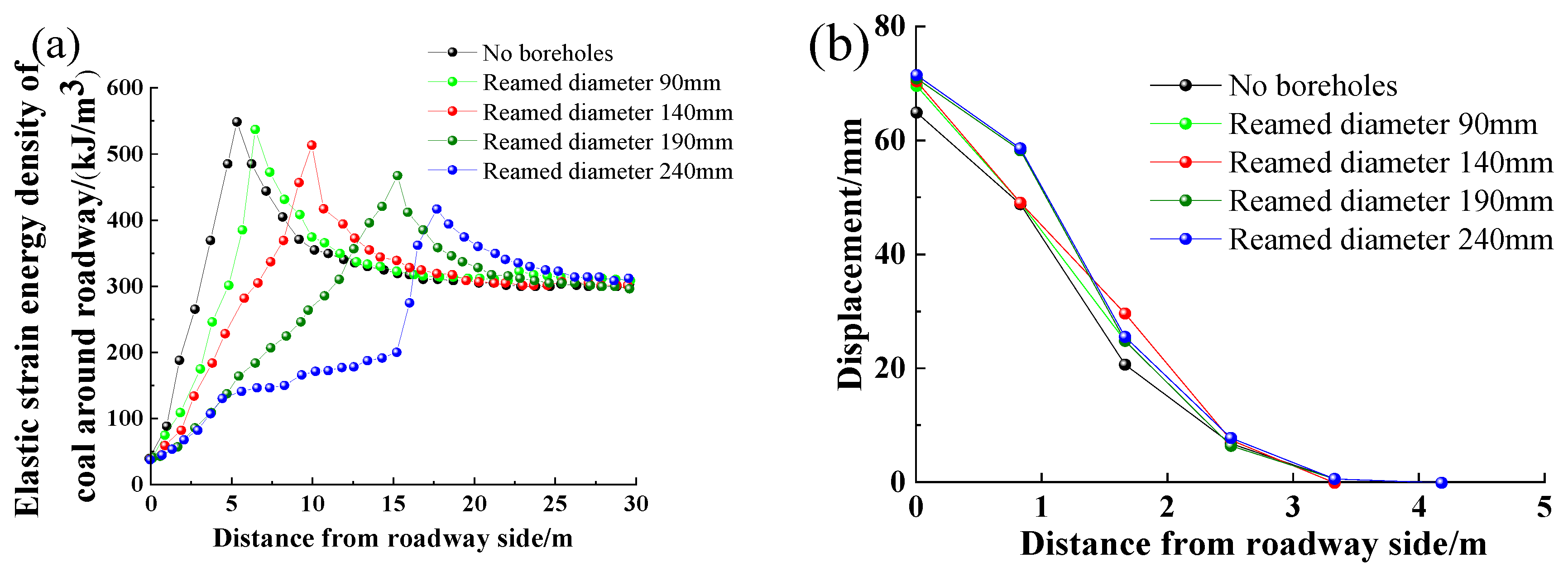
Figure 14a shows the influence of different reaming diameters on elastic energy distribution around the roadway. The elastic strain energy of coal around the roadway of the working face without drilling is accumulated, and the peak density is 5.486 × 10⁵ J. The value decreases with the increased reaming section diameter. If the reaming section diameter is 190 mm, the elastic strain energy accumulation of coal around the roadway is weakened, and the energy release areas of each borehole are connected. Energy accumulation around the roadway is transferred to the end of the borehole when the reaming diameter is 240 mm [37]. The elastic energy of coal around the roadway is released with the increased reaming section diameter. The distance between coal with elastic strain energy accumulation and the roadway increases, while the strain energy peak and energy gradient decrease.
(2)
Deformation characteristics of the surrounding rocks of the roadway
Figure 14b shows that the two sides’ displacement of the roadway in the undrilled working face is 64.9 mm. The two sides’ displacement with a reaming diameter of 90 mm is 69.5 mm, which is 4.6 mm higher than that of the two sides without pressure relief. If the reaming diameters are 140, 190, and 240 mm, respectively, the two sides’ displacements of the working face roadway are 70.8, 72.0, and 72.3 mm, respectively. The two sides’ displacement with a reaming diameter of 90 mm increased by 1.3, 2.5, and 2.8 mm, respectively.
Pressure relief by drilling can affect roadway stability and increase the two sides’ displacement. However, the increased reaming diameter reduces the displacement change and anchoring effect of the roadway’s two sides. Therefore, the increased reaming diameter improves the pressure relief effect instead of the anchoring effect of the roadway. The diameter of the reaming hole in the dangerous area of the 6307 working face is 240 mm, according to the actual construction of the working face.

4.2.2. Simulation Scheme 2: Simulation Results Analysis

(1)
Energy release characteristics of the surrounding rocks of the roadway
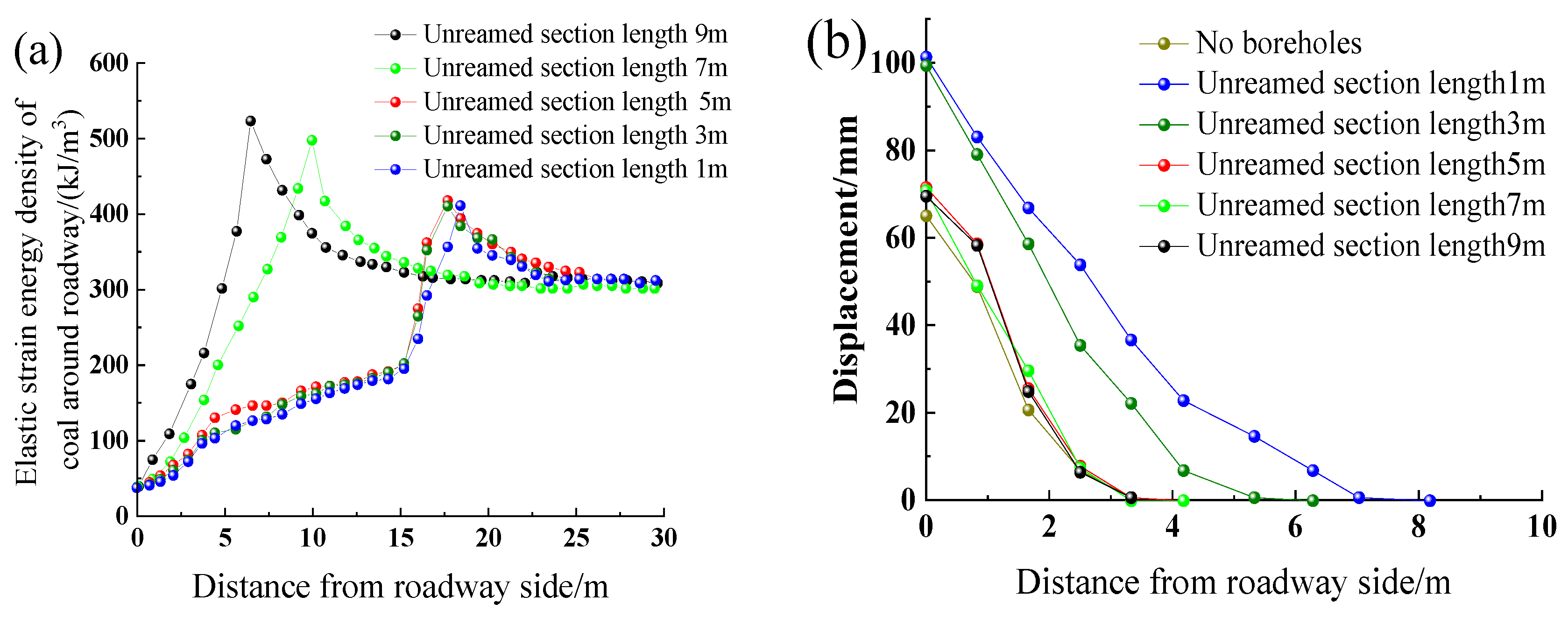
Figure 15a shows the influence of boreholes with different reaming depths on the elastic energy distribution around the roadway. When the non-reaming section depths of pressure relief by drilling are 7 and 9 m, respectively, the energy release of coal around the roadway is not obvious. When the depths are 1, 3, and 5 m, respectively, the strain energy peak and energy gradient are similar and decrease, with a significant pressure relief effect.
(2)
Deformation characteristics of the tunnel surrounding the rock
Figure 15b shows that compared with the unexpanded section, the displacement of the two gangs increased by 36.3, 34.4, 7.4, 5.8, and 4.5 mm when the length of the unexpanded section was 1, 3, 5, 7, and 9 m, respectively. The implementation of the pressure relief drilling affected the stability of the roadway, which increases the displacement of the two sides. Especially when the length of the unexpanded section is less than 5 m, the displacement of the two sides of the roadway increases significantly, and the displacement of the two sides of the roadway does not increase much when it exceeds 5 m. Therefore, combining the effect of the pressure relief and drilling cost, the depth of the unexpanded section in the impact hazard area of the transport chute of the 6307 working face is determined to be 5 m, and the depth of the expanded section is 15 m.

4.2.3. Simulation Scheme 3: Simulation Results Analysis

(1)
Energy release characteristics of the surrounding rocks of the roadway
Figure 16a shows the influence of borehole spacings on the elastic energy distribution around the roadway. Elastic strain energy release of coal around the roadway increases with the decreased borehole spacing after pressure relief by drilling [38]. The coal range involved in strain energy release is expanded. When the borehole spacings are 0.8, 1.6, 2.4, and 3.2 m, the peak values of elastic strain energy of coal around the roadway are 4.103 × 10⁵, 4.175 × 10⁵, 4.675 × 10⁵, and 5.141 × 10⁵ J, respectively.
If the borehole spacing is too large (3.2 m), the pressure relief areas around each borehole reaming section are independent and does not penetrate each other. Thus, the pressure relief of the borehole fails to adjust the energy accumulation of coal around the roadway. When the borehole spacing is reduced to 2.4 m, the pressure relief areas around the reaming sections of each borehole in the peak value scope connect. The pressure relief of the borehole can adjust the energy accumulation of coal around the roadway. When the borehole spacing is reduced to 1.6 and 0.8 m, the energy release effect of coal around the roadway is obvious.
(2)
Deformation characteristics of surrounding rocks of the roadway
Figure 16b shows the displacement curve of two sides with borehole spacings. When the distances are 0.8, 1.6, 2.4, and 3.2 m, the displacements of the two sides are 103.3, 79.5, 76.9, and 74.1 mm, respectively. The roadway deformation with a borehole spacing of 3.2 m is small. The decreased borehole spacing slightly increases the deformation of the two sides.
Small borehole spacing (reduced to 0.8 m) destroys the bearing structure of coal and the displacement of the two sides increases. Therefore, the roadway energy release of surrounding rocks and the pressure relief effect of segmented reaming becomes better with the decreased borehole spacing. Meanwhile, the increased surrounding rock displacement tends to be gentle and then increases sharply. The borehole spacing in the haulage gate impact zone of the 6307 working face is determined to be 1.8 m combined with the actual construction of the working face.

5. Results and Discussion

5.1. Results

The simulation results of the segmented reaming parameter arrangement show that reaming drills in a single row can relieve the side drilling pressure of coal in the monitored high bump danger area. Borehole spacings are 1.6 and 1.2–1.5 m from the roadway floor, and the hole depth is 20 m. The borehole diameter in the 0–5 m section is 90 mm, and that in the 5–20 m section is 240 mm. The alloy blades inside the pdc ream bit open after drilling for 5 m with pressurized water, and the drilling diameter increases from 90 to 240 mm.
Figure 17 shows the plan view and sectional drawing of the segmented reaming parameters. The implementation location is the haulage gate of the 6307 working face in the 630# mining area of the Tangkou coal mine and the 100 m high bump danger area are tested.
(1)
Effect test of stress release measurements of segmented reaming
We carried out the following operations in the haulage gate test area of the 6307 working face to test the anti-scour effect of segmented reaming pressure relief: A drilling-cuttings inspection hole was constructed every 20 m, with a total of six groups and two in each group. Figure 18 presents the monitored coal quantity distribution. The monitoring of drilling cuttings shows that the segmented reaming pressure relief in the test area reduces rock burst.
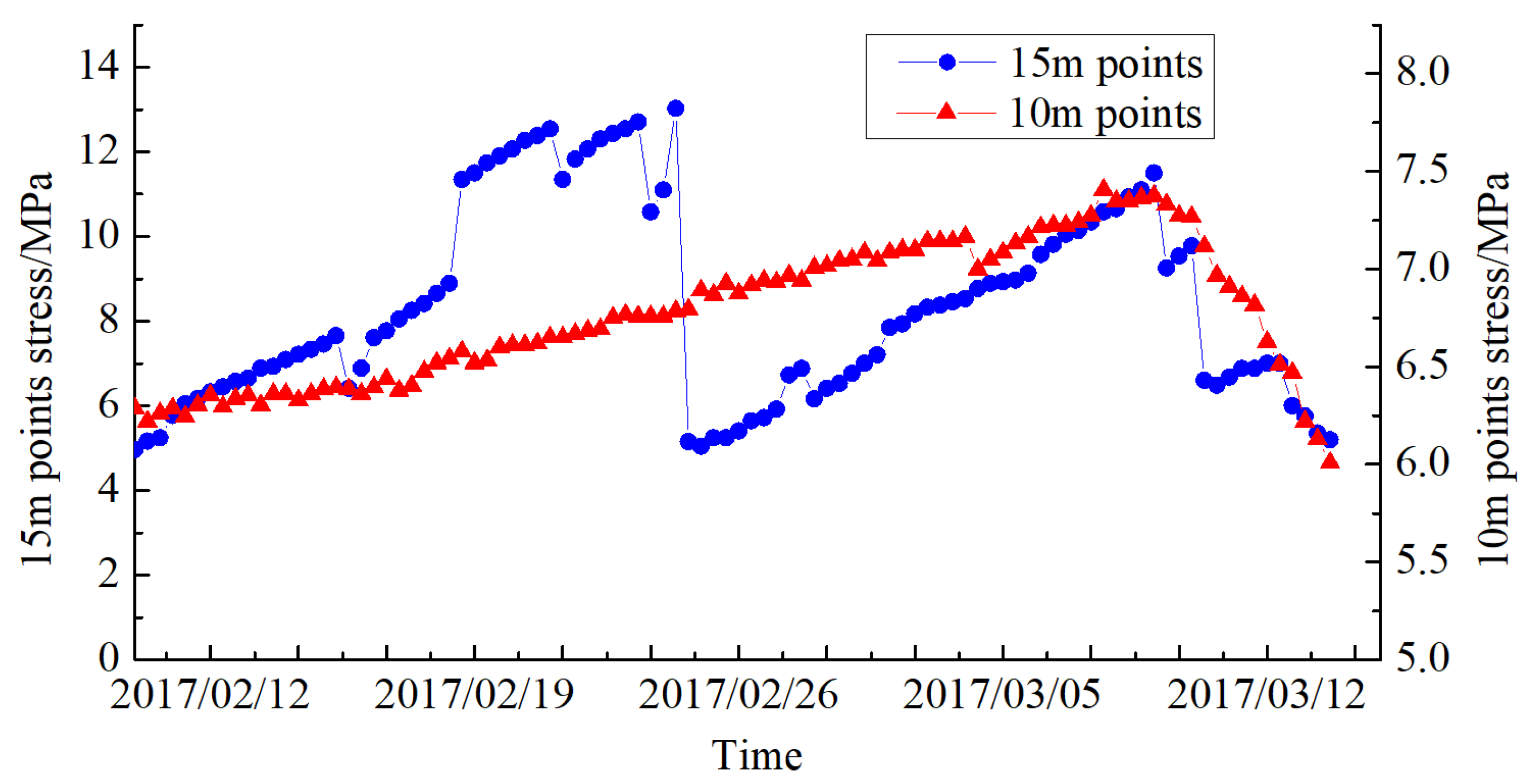
The coal stress meter can monitor the coal stress and reflects its release and transfer after segmented reaming. Figure 19 shows the monitoring data of coal stress in the test area, in which the coal stress meter is located between two pressure relief boreholes.
Figure 19 shows that the pressure of coal stress located in the 10-meter-shallow hole at the haulage gate test side is small (6.5 MPa) with the advancement of the 6307 working face. However, the yellow warning value of a shallow hole is 11–14 MPa, indicating no impact risk. The peak pressure of the coal stress meter at the 15-meter-deep hole is reduced from 13 to 5.3 MPa, and the adjacent large-diameter boreholes collapse. Therefore, coal is subjected to yield failure for large-diameter boreholes (the width of the energy dissipation zone increases), with high stress or energy released and coal in the yield state. The above analysis shows that segmented reaming technology can reduce coal stress accumulation and rock burst risks.
(2)
Deformation observation of the surrounding rocks of the roadway
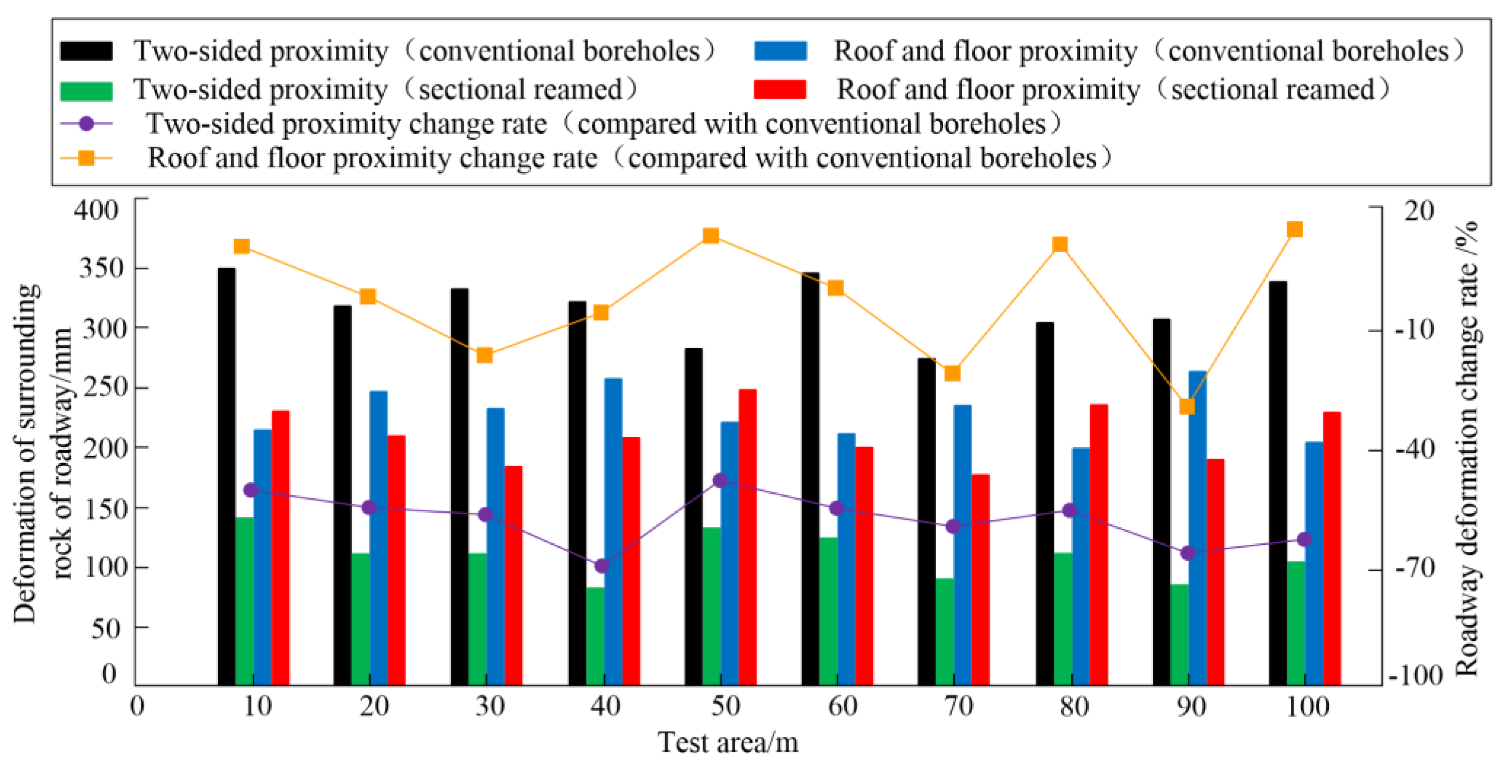
Observation points were set up at a distance of 10 m within 100 m of the segmented reaming pressure relief area in the 6307 working face, and 10 monitoring points were selected. Then, the subsidence of the roof, floor heave, and left–right sides of the roadway are monitored regularly. The roadway deformation of the two pressure relief methods is analyzed by comparing the roadway deformation in the construction area of conventional, large-diameter drilling.
The monitoring sections in the segmented reaming pressure relief area of the 6307 working face can be compared with roadway deformation monitoring data in the borehole pressure relief construction area with a conventional, large diameter. Figure 20 shows that the deformation of the roadway roof and floor and the two sides in the segmented reaming pressure relief area is lower than that in the conventional, large-diameter drilling construction area. The deformation of the two sides changes significantly.
The roof-to-floor convergence of the roadway construction area with pressure relief by drilling with a conventional, large diameter in the haulage gate of the 6307 working face is 255 mm. However, the maximum roof-to-floor convergence of the roadway in the pressure relief area of the segmented reaming is 236 mm, which is 7.5% lower than that of the conventional, large diameter. The maximum displacement of the roadway’s two sides in the conventional, large-diameter borehole pressure relief construction area of the 6307 working face is 350 mm; that in the segmented reaming pressure relief area is 153 mm, which is 56.3% lower than the former. Therefore, the influence of segmented reaming technology on roadway deformation is small.
(3)
Construction efficiency analysis
Table 3 compares the construction parameters within 100 m of the segmented reaming pressure relief area of the 6307 working face with those in the conventional, large-diameter borehole pressure relief construction area. It analyzes the construction efficiency of segmented reaming technology. The single-hole powder discharge amount of segmented reaming pressure relief construction is 1.17 t, which is 1.9 times that of the ordinary pressure relief hole. Three staff are fixed to construct pressure relief holes in the selected area according to the construction efficiency comparison, and the pressure relief engineering time of the 100-meter groove is compared under the same operation time.
The construction of the 100-meter roadway in pressure relief by drilling with a conventional, large diameter needs 31.25 shifts (100 m/0.8 m/4/shift), while segmented reaming pressure relief drilling needs 20.83 shifts (100 m/1.6 m/3/shift). The construction efficiency of segmented reaming pressure relief is 1.5 times that of the original pressure relief method under the same conditions. The conventional, large-diameter pressure relief requires sealing boreholes to reduce the impact of borehole pressure relief on roadway stability. The sealing quality affects roadways. However, the pressure relief of segmented reaming does not need to reinforce the sealing hole, and the blasting mud sealing hole can avoid the spontaneous combustion of coal in the hole. The pressure relief construction effect of segmented reaming is better than that of conventional, large-diameter pressure relief.

5.2. Discussion

Stress and energy in coal have been released and transmitted through the on-site testing of the application effect of segmented reaming technology in the Tangkou coal mine. It reduced stress accumulation in coal and controlled the deformation of the surrounding rocks of the roadway. Work efficiency increased, with reduced coal seam impacts. The successful application of segmented reaming technology provides a technical reference for the prevention and control of pressure relief in mines with similar impacts.

6. Conclusions and Outlook

We performed conventional, large-diameter pressure relief by drilling in the Tangkou coal mine. Compared with the non-use of pressure relief measures, the roof and floor displacements did not change much. However, the displacement between the two sides increased by 147 mm due to the influence of pressure relief from drilling. To this end, segmented reaming pressure relief was proposed.
The effects of the diameter, depth, and borehole spacing of the reaming section on the strength of specimens and surrounding crack propagation were studied in indoor experiments. The results showed that the pressure relief effect was positively correlated with the reaming diameter and depth, while it was negatively correlated with the spacing between boreholes.
The segmented reaming parameters are finally determined as follows through a comparative analysis of the anti-impact and pressure relief effects of different segmented reaming parameters of the Tangkou coal mine: The spacing between boreholes was 1.6 m, with a drilling depth of 20 m; the drilling length and diameter of the non-pressure relief section are 5 and 90 mm, respectively; and the drilling length and diameter of the reaming section are 15 and 240 mm, respectively.
The optimized segmented reaming parameters were used for on-site testing and monitoring. The displacement on both sides of the roadway was reduced by 56.3% after the segmented reaming pressure relief in the transport channel of the working surface. It verifies the effectiveness of segmented reaming pressure relief.
This work proposes a segmented reaming technology. Then, the mechanism of segmented reaming pressure relief was explained from the perspective of coordinated control of roadway deformation and pressure relief effects. However, the following needs to be further studied: (1) The superposition of the secondary distribution stress of the coal roadway side and the stress of the drilling diameter of segmented reaming pressure relief to the expansion area. (2) The theory of weakening the mechanical model of coal in space by the drilling diameter of pressure relief by segmented reaming.

Author Contributions

Conceptualization, W.W. and Y.Y.; methodology, W.W. and K.D.; software, Z.C. and L.L.; investigation, B.Z. and A.S.K.; resources, Y.Y. and Y.X.; data curation, W.W.; writing—original draft preparation, W.W.; writing—review and editing, Y.Y., K.D., C.Z. and Z.C.; project administration, W.W. and Y.Y.; funding acquisition, Y.Y. and C.Z. All authors have read and agreed to the published version of the manuscript.

Funding

This work was supported by the National Natural Science Foundation of China (51974294), the Qing Lan Project of Jiangsu Province Universities (2022), and the Research Fund of Key Laboratory of Deep Coal Resource Mining (CUMT), Ministry of Education (KLDCRM202205).

Data Availability Statement

The data used to support the findings of this study are included within the article.

Conflicts of Interest

The authors declare no conflict of interest.

References

  1. Zhang, C.; Canbulat, I.; Hebblewhite, B.; Ward, C.R. Assessing coal burst phenomena in mining and insights into directions for future research. Int. J. Coal Geol. 2017, 179, 28–44. [Google Scholar] [CrossRef]
  2. Li, T.; Cai, M.F.; Cai, M. A review of mining-induced seismicity in China. Int. J. Rock Mech. Min. Sci. 2007, 44, 1149–1171. [Google Scholar] [CrossRef]
  3. Yan, P.; Zhao, Z.; Lu, W.; Fan, Y.; Chen, X.; Shan, Z. Mitigation of rock burst events by blasting techniques during deep-tunnel excavation. Eng. Geol. 2015, 188, 126–136. [Google Scholar] [CrossRef]
  4. Dou, L.-M.; Mu, Z.-L.; Li, Z.-L.; Cao, A.-Y.; Gong, S.-Y. Research progress of monitoring, forecasting, and prevention of rockburst in underground coal mining in China. Int. J. Coal Sci. Technol. 2014, 1, 278–288. [Google Scholar] [CrossRef]
  5. Jiang, Y.; Wang, H.; Xue, S.; Zhao, Y.; Zhu, J.; Pang, X. Assessment and mitigation of coal bump risk during extraction of an island longwall panel. Int. J. Coal Geol. 2012, 95, 20–33. [Google Scholar] [CrossRef]
  6. Hosseini, N. Evaluation of the rockburst potential in longwall coal mining using passive seismic velocity tomography and image subtraction technique. J. Seismol. 2017, 21, 1101–1110. [Google Scholar] [CrossRef]
  7. Mazaira, A.; Konicek, P. Intense rockburst impacts in deep underground construction and their prevention. Can. Geotech. J. 2015, 52, 1426–1439. [Google Scholar] [CrossRef]
  8. Hongwei, W.; Yaodong, J.; Jie, Z.; Ruyue, S.; Chen, W. Numerical investigation on the assessment and mitigation of coal bump in an island longwall panel. Int. J. Min. Sci. Technol. 2013, 23, 625–630. [Google Scholar] [CrossRef]
  9. Li, Z.L.; Dou, L.M.; Cai, W.; Wang, G.F.; Ding, Y.L.; Kong, Y. Roadway stagger layout for effective control of gob-side rock bursts in the longwall mining of a thick coal seam. Rock Mech. Rock Eng. 2016, 49, 621–629. [Google Scholar] [CrossRef]
  10. Liu, H.B.; Zhao, Y.X.; Jiang, Y.D.; Wang, H. Large diameter borehole pressure relief and disaster prevention technology in fully mechanized caving face. Saf. Coal Mines 2018, 9, 79–82. (In Chinese) [Google Scholar]
  11. Lei, X.Y.; Zhu, X.W. Simulated analysis of pressure relief by forward drilling in high stress roadway. Saf. Coal Mines 2015, 46, 175–178. (In Chinese) [Google Scholar]
  12. Zhao, T.B.; Guo, W.Y.; Tan, Y.L.; Lu, C.P.; Wang, C.W. Case histories of rock bursts under complicated geological conditions. Bull. Eng. Geol. Environ. 2017, 77, 1529–1545. [Google Scholar] [CrossRef]
  13. Li, Y.P.; Zhang, H.W.; Zhu, Z.J.; Chao, G. Study on safety parameters of pressure relief boreholes in percussive dangerous coal seams. China Saf. Sci. J. 2018, 28, 122–128. (In Chinese) [Google Scholar]
  14. Zhang, S.C.; Li, Y.Y.; Shen, B.T.; Sun, X.Z.; Gao, L.Q. Effective evaluation of pressure relief drilling for reducing rock bursts and its application in underground coal mines. Int. J. Rock Mech. Min. Sci. 2019, 114, 7–16. [Google Scholar] [CrossRef]
  15. Meier, T.; Rybacki, E.; Reinicke, A.; Dresen, G. Influence of borehole diameter on the formation of borehole breakouts in black shale. Int. J. Rock Mech. Min. Sci. 2013, 62, 74–85. [Google Scholar] [CrossRef]
  16. Huang, B.; Guo, W.Y.; Fu, Z.Y.; Zhao, T.B.; Zhang, L.S. Experimental Investigation of the Influence of Drilling Arrangements on the Mechanical Behavior of Rock Models. Geotech. Geol. Eng. 2018, 36, 2425–2436. [Google Scholar] [CrossRef]
  17. Jia, C.; Jiang, Y.; Zhang, X.X. Laboratory and numerical experiments on pressure relief mechanism of large-diameter boreholes. Chin. J. Geot. Eng. 2017, 39, 1115–1122. (In Chinese) [Google Scholar]
  18. Shen, B.; Stephansson, O.; Rinne, M. Simulation of borehole breakouts using fracod (2d). Oil Gas Sci. Technol. 2002, 57, 579–590. [Google Scholar] [CrossRef]
  19. Song, D.; Wang, E.; Li, Z.; Liu, J.; Xu, W. Energy dissipation of coal and rock during damage and failure process based on EMR. Int. J. Min. Sci. Technol. 2015, 85, 17–30. [Google Scholar] [CrossRef]
  20. Sainoki, A.; Mitri, H.S. Dynamic modelling of fault-slip with Barton’s shear strength model. Int. J. Rock Mech. Min. Sci. 2014, 67, 155–163. [Google Scholar] [CrossRef]
  21. Wang, L.; Lu, Z.L.; Gao, Q. A numerical study of rock burst development and strain energy release. Int. J. Min. Sci. Technol. 2012, 22, 675–680. [Google Scholar] [CrossRef]
  22. Zhao, Y.X.; Jiang, Y.D. Acoustic emission and thermal infrared precursors associated with bump-prone coal failure. Int. J. Coal Geol. 2010, 83, 11–20. [Google Scholar] [CrossRef]
  23. Prusek, S.; Masny, W. Analysis of damage to underground workings and their supports caused by dynamic phenomena. J. Min. Sci. 2015, 51, 63–72. [Google Scholar] [CrossRef]
  24. Guo, W.-Y.; Zhao, T.-B.; Tan, Y.-L.; Yu, F.-H.; Hu, S.-C.; Yang, F.-Q. Progressive mitigation method of rock bursts under complicated geological conditions. Int. J. Rock Mech. Min. Sci. 2017, 96, 11–22. [Google Scholar] [CrossRef]
  25. Zhao, T.-B.; Guo, W.-Y.; Tan, Y.-L.; Yin, Y.-C.; Cai, L.-S.; Pan, J.-F. Case studies of rock bursts under complicated geological conditions during multi-seam mining at a depth of 800 m. Rock Mech. Rock Eng. 2018, 51, 1539–1564. [Google Scholar] [CrossRef]
  26. Wang, W.; Yuan, Y.; Chen, Z.; Zhu, C. Physical Modeling of Floor Failure Above Confined Water: A Case Study in China. Environ. Earth Sci. 2022, 81, 325. [Google Scholar] [CrossRef]
  27. Zhu, C.; Yuan, Y.; Wang, W.; Chen, Z.; Zhong, H. Research On the “Three Shells” Cooperative Support Technology of Large-Section Chambers in Deep Mines. Int. J. Min. Sci. Technol. 2021, 31, 665–680. [Google Scholar] [CrossRef]
  28. Yuan, Y.; Yuan, C.; Zhu, C.; Liu, H.; Wang, S. Study on the Disaster Reduction Mechanism of Presplitting Blasting and Reasonable Blasting Parameters for Shallowly Buried Remnant Pillars. Energy Sci. Eng. 2019, 7, 2884–2894. [Google Scholar] [CrossRef]
  29. Zhou, F.; Sun, W.; Shao, J.; Kong, L.; Geng, X. Experimental Study on Nano Silica Modified Cement Base Grouting Reinforcement Materials. Geomech. Eng. 2020, 20, 67–73. [Google Scholar]
  30. Song, W.; Liang, Z. Theoretical and Numerical Investigations on Mining-Induced Fault Activation and Groundwater Outburst of Coal Seam Floor. Bull. Eng. Geol. Environ. 2021, 80, 5757–5768. [Google Scholar] [CrossRef]
  31. Wang, W.; Yuan, Y.; Liang, X.; Qin, Z.; Chen, Z.; Ding, K.; Xia, Y.; Yan, C. Experimental Study on Floor Damage and Slurry Material Ratio Optimization in Deep and High Confined Water Mining. Processes 2022, 10, 1806. [Google Scholar] [CrossRef]
  32. Zhu, C.; Yuan, Y.; Yuan, C.; Liu, F.; Chen, Z.; Wang, S. Study on the Structural Forms of the Key Strata in the Overburden of a Stope During Periodic Weighting and the Reasonable Working Resistance of the Support. Energy Sci. Eng. 2020, 8, 2599–2620. [Google Scholar] [CrossRef]
  33. Sun, Y.; Zhang, P.; Yan, W.; Wu, J.; Yan, F. Grouting Material Development and Dynamic Grouting Test of Broken Rock Mass. J. Mater. Civ. Eng. 2022, 34, 4022072. [Google Scholar] [CrossRef]
  34. Hu, Y.; Li, W.; Wang, Q.; Liu, S.; Wang, Z. Study on Failure Depth of Coal Seam Floor in Deep Mining. Environ. Earth Sci. 2019, 78, 697. [Google Scholar] [CrossRef]
  35. Xu, Z.; Sun, Y.; Gao, S.; Chen, H.; Li, X. Comprehensive Exploration, Safety Evaluation and Grouting of Karst Collapse Columns in the Yangjian Coalmine of the Shanxi Province, China. Carbonates Evaporites 2021, 36, 16. [Google Scholar] [CrossRef]
  36. Yu, S.; Xu, J.; Zhu, W.; Wang, S.; Liu, W. Development of a Combined Mining Technique to Protect the Underground Workspace Above Confined Aquifer from Water Inrush Disaster. Bull. Eng. Geol. Environ. 2020, 79, 3649–3666. [Google Scholar] [CrossRef]
  37. Liang, Z.; Song, W.; Liu, W. Theoretical Models for Simulating the Failure Range and Stability of Inclined Floor Strata Induced by Mining and Hydraulic Pressure. Int. J. Rock Mech. Min. Sci. 2020, 132, 104382. [Google Scholar] [CrossRef]
  38. Zhu, C.; Yuan, Y.; Chen, Z.; Meng, C.; Wang, S. Study of the Stability Control of Rock Surrounding Longwall Recovery Roadways in Shallow Seams. Shock Vib. 2020, 2020, 1–22. [Google Scholar] [CrossRef]
Figure 1. Layout plan of the 6307 working face.
Processes 11 01235 g001
Figure 2. (a) Layout plan. (b) Layout profile. Layout of major diameter and pressure relief boreholes.
Processes 11 01235 g002
Figure 3. Surface displacement monitoring curve of the roadway: (a) unconstructed pressure relief boreholes; (b) constructed pressure relief boreholes.
Processes 11 01235 g003
Figure 4. Stress monitoring curve of bolt: (a) schematic diagram of roadway support; (b) bolt’s stress.
Processes 11 01235 g004
Figure 5. Comparison of pressure relief effects under different drilling pressure relief methods: (a) elastic energy distribution diagram; (b) displacement diagram.
Processes 11 01235 g005
Figure 6. Mechanism of segmented reaming pressure relief ( σ p , L p represent the peak stress and the corresponding position before pressure relief, respectively; σ p , L p represent the peak stress and the corresponding position after segmented reaming pressure relief).
Processes 11 01235 g006
Figure 7. Stress–strain curves of specimens with different enlarged apertures.
Processes 11 01235 g007
Figure 8. (a) Unenlarged borehole. (b) Borehole diameter of 6 mm. (c) Borehole diameter of 9 mm. Macroscopic failure of specimens with different enlarged borehole diameters.
Processes 11 01235 g008aProcesses 11 01235 g008b
Figure 9. Stress–strain curves of specimens with different boreholes enlargement depths.
Processes 11 01235 g009
Figure 10. (a) Reaming depth of 15 mm. (b) Reaming depth of 25 mm. (c) Reaming depth of 35 mm. Macroscopic failure diagrams of specimens with different enlarged depths of boreholes.
Processes 11 01235 g010aProcesses 11 01235 g010b
Figure 11. (a) Reaming depth of 15 mm. (b) Reaming depth of 25 mm. (c) Reaming depth of 35 mm. Side failure of specimens.
Processes 11 01235 g011
Figure 12. Stress–strain curves of specimens with different boreholes spacing.
Processes 11 01235 g012
Figure 13. (a) Borehole spacing of 15 mm. (b) Borehole spacing of 22.5 mm. (c) Borehole spacing of 30 mm. Macroscopic failure of specimens with different borehole spacings.
Processes 11 01235 g013aProcesses 11 01235 g013b
Figure 14. Scheme 1 simulation results: (a) elastic energy distribution curve around roadway; (b) displacement curve of roadway surrounding.
Processes 11 01235 g014
Figure 15. Scheme 2 simulation results: (a) elastic energy distribution curves around roadway; (b) displacement curves of roadway surrounding.
Processes 11 01235 g015
Figure 16. Scheme 3 simulation results: (a) elastic energy distribution curve around roadway; (b) displacement curve of roadway surrounding.
Processes 11 01235 g016
Figure 17. Layout of segmented reaming pressure relief boreholes: (a) plan view of segmented reaming parameters layout; (b) sectional drawing of segmented reaming parameter layout.
Processes 11 01235 g017
Figure 18. Pulverized coal quantity distribution curves: (a) coal quantity distribution in inner coal wall; (b) coal quantity distribution in outer coal wall.
Processes 11 01235 g018
Figure 19. Coal stress monitoring curve.
Processes 11 01235 g019
Figure 20. Monitoring curve of maximum deformation of surrounding rocks of the roadway during observation.
Processes 11 01235 g020
Table 1. Design of test scheme.
Serial NumberTest SchemeParameterDiagrammatic SketchPhysical Pictures
1Different diameters of enlarged boreholes3 mmProcesses 11 01235 i001Processes 11 01235 i002Processes 11 01235 i003Processes 11 01235 i004Processes 11 01235 i005Processes 11 01235 i006
6 mm
9 mm
2Different boreholes enlargement depth15 mmProcesses 11 01235 i007Processes 11 01235 i008Processes 11 01235 i009Processes 11 01235 i010Processes 11 01235 i011Processes 11 01235 i012
25 mm
35 mm
3Different boreholes spacing15 mmProcesses 11 01235 i013Processes 11 01235 i014Processes 11 01235 i015Processes 11 01235 i016Processes 11 01235 i017Processes 11 01235 i018
Table 2. Simulation scheme design.
Serial NumberDrilling Depth (m)Drill Hole Spacing (m)Unexpanded SectionReaming Section
Length (m)Diameter (m)Length (m)Diameter (mm)
Simulation Scheme 120--5901590, 140, 190, and 240
Simulation Scheme 21.61, 3, 5,
7, and 9
9019, 17, 15,
13, and 11
240
Simulation Scheme 30.8, 1.6, 2.4, and 3.25901590, 140, 190, and 240
Table 3. Contrast of construction parameters of pressure relief boreholes.
Pressure Relief TechnologyConventional, Large-Diameter Boreholes Pressure ReliefDecompression by Piecewise Reaming
Boreholes diameter150 mm1–5 m is 90 mm; 5–20 m is 240 mm
Construction efficiencyFour in each class (considering sealing time)Three in each class (no sealing time)
Drill pipeΦ89 mm high-efficiency screw drill pipeΦ63 mm wide blade drill pipe
Number of boreholes per hundred meters250125
Boreholes spacing0.8 m1.6 m
Single-borehole powder discharge0.55 t1.17 t
Coal powder discharge per meter of roadway0.34 t0.37 t
Construction time of single borehole2 h2.7 h
Construction efficiencyThe construction of 20 boreholes in a 16-meter roadway requires 5 shifts and 11 tons of coal powder dischargeThe construction of 10 boreholes in a 16-meter roadway requires 3.3 shifts and 11.7 tons of coal powder discharge
Disclaimer/Publisher’s Note: The statements, opinions and data contained in all publications are solely those of the individual author(s) and contributor(s) and not of MDPI and/or the editor(s). MDPI and/or the editor(s) disclaim responsibility for any injury to people or property resulting from any ideas, methods, instructions or products referred to in the content.