

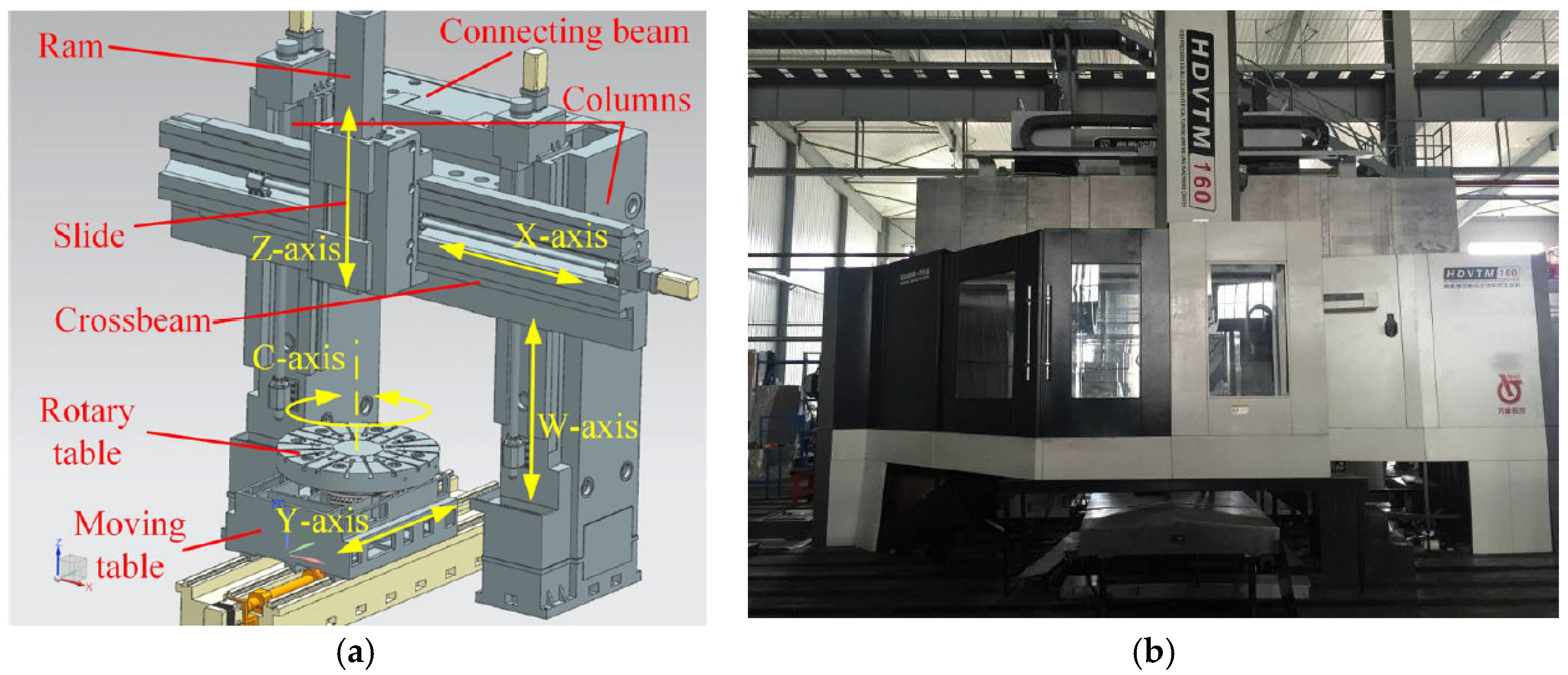
Modelling and Analysis of Dynamic Servo Error of Heavy Vertical Machining Centre Considering Nonlinear Factors


Abstract
:1. Introduction
- (1)
- The mechanical transmission system model is derived based on the modelling approach used for conventional CNC machine tools. These models represent the mechanical transmission simply using a second-order model, ignoring the change of stiffness caused by the large distances travelled, and the long transmission chains of the heavy-duty machine tools. At the same time, the non-linear change in friction caused by the change of oil film thickness in the hydrostatic guideway, due to the large inertia and large load of the heavy-duty machine tool, is ignored.
- (2)
- The modelling of the servo drive system is often ignored, and the classic PID is used for the error model. This results in a situation where the theoretical model does not match the actual machine tool behaviour. The error model formulated in this scenario will consequently result in imprecise analysis of error-inducing factors, thereby complicating the provision of theoretical guidance for effectively reducing errors in heavy machine tools.
2. Modelling of the Servo Feed System in a Heavy-Duty Vertical Machining Centre
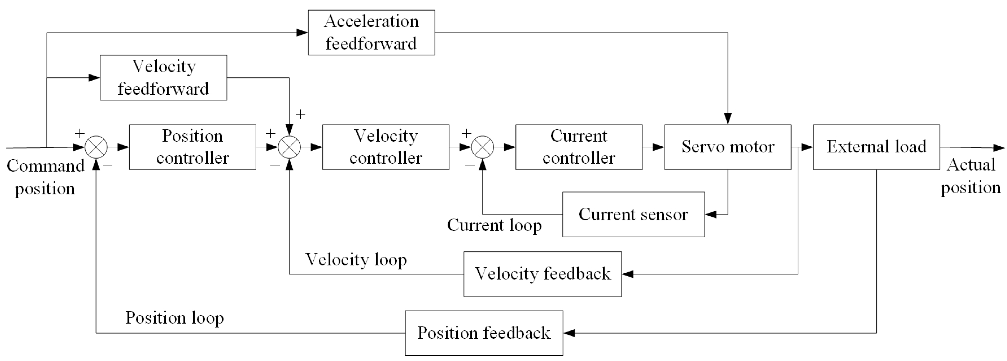
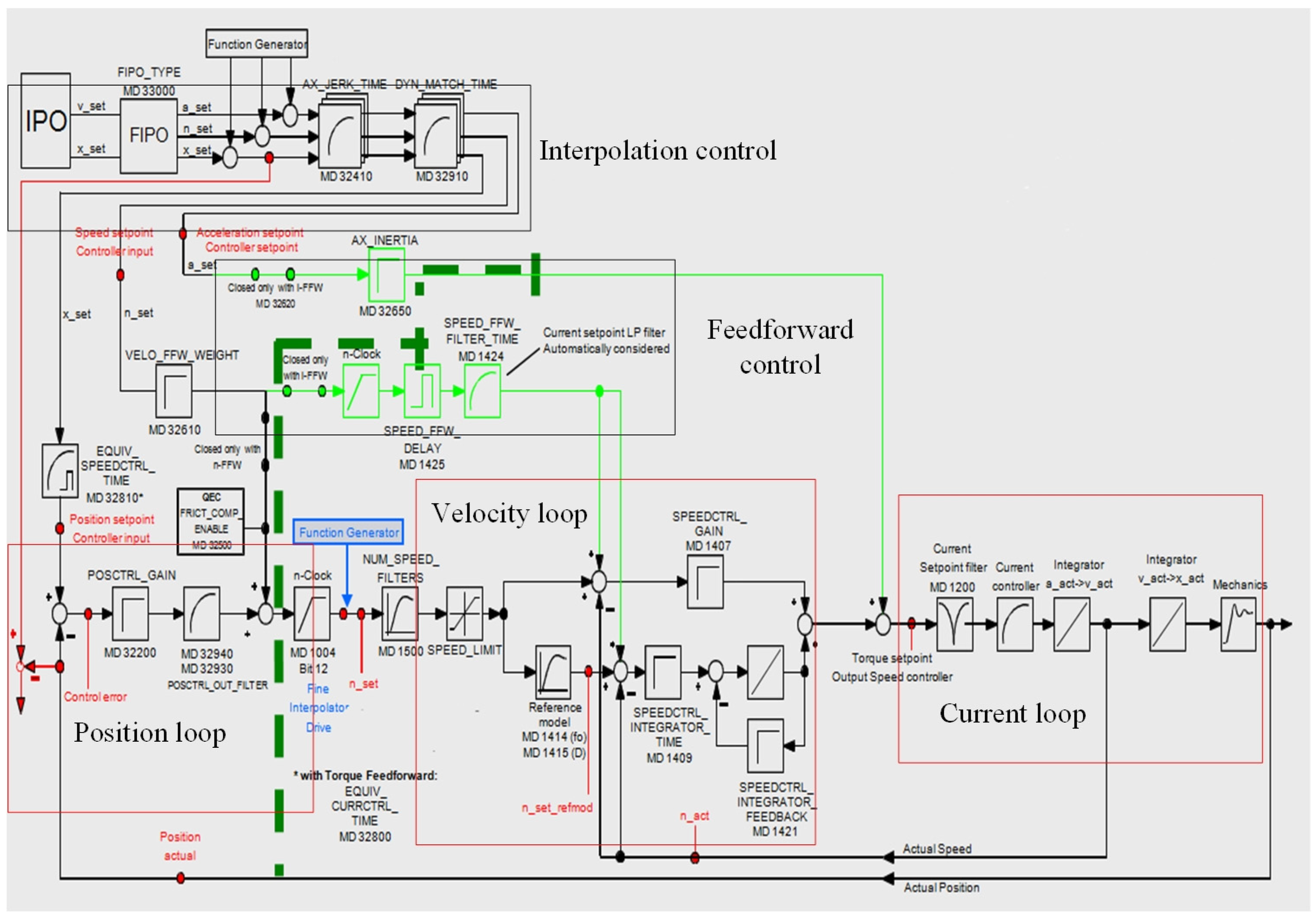
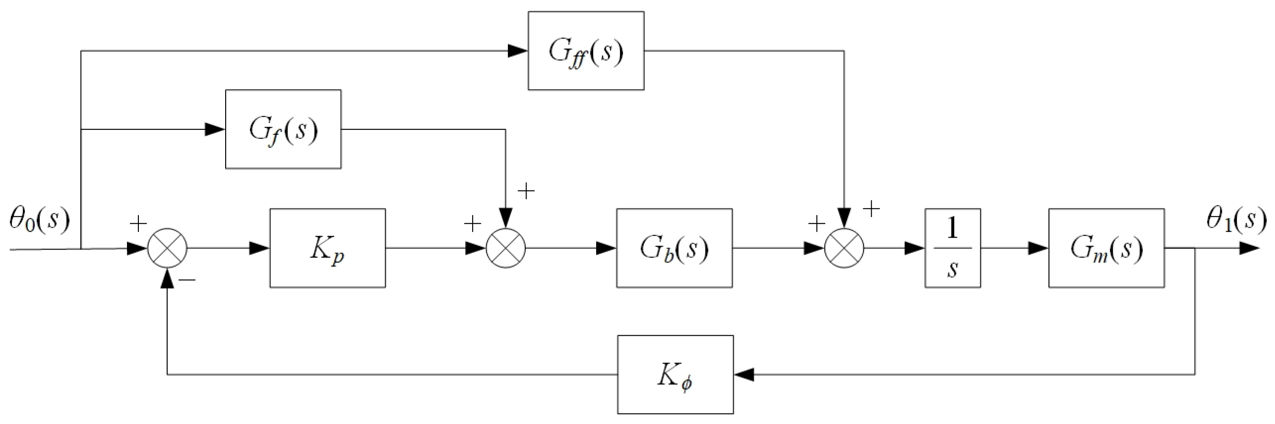
2.1. Development of a Theoretical Model of a Servo Drive System
- (1)
- Mathematical model of the current loop
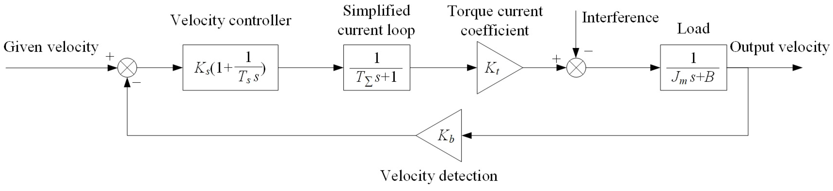
- (2)
- Mathematical model of the velocity loops
- (3)
- Mathematical model of the position loop
2.2. Development of the Theoretical Model of the Mechanical Transmission System
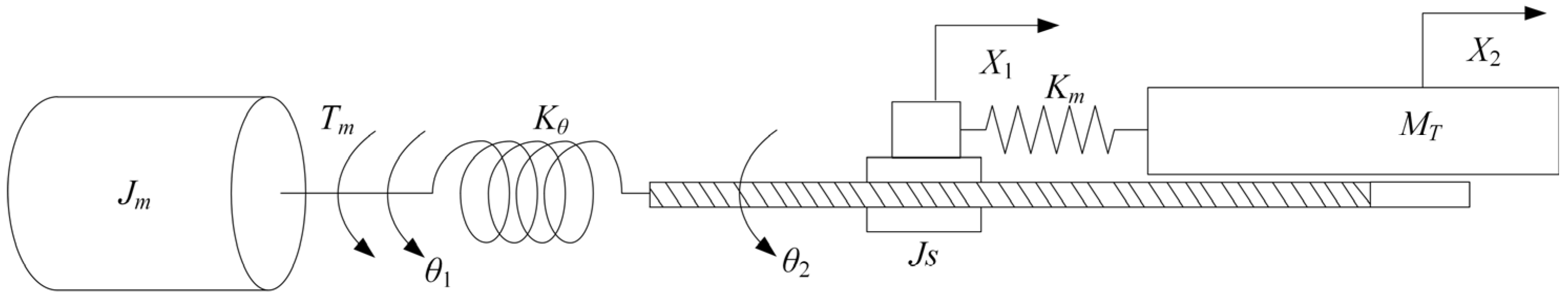
2.2.1. Modelling of Ball Screw Transmission
- Jm
- is the total converted moment of inertia of the motor rotor, coupling and gear reducer (kg∙m2);
- Tm
- is the torque output by the motor (N·m);
- θ1
- is the rotation angle of the gearbox output shaft (rad);
- θ2
- is the rotation angle of the ball screw (rad);
- it
- is the transmission ratio of the gear reducer;
- X1
- is the converted translational displacement of the lead screw (m);
- X2
- is the displacement of the worktable (m);
- Js
- is the total moment of inertia at one end of the ball screw and coupling (kg∙m2);
- MT
- is the total mass of the worktable and screw nut (kg);
- P
- is the pitch of the ball screw (m);
- Kθ
- is the comprehensive torsional stiffness (N·m/rad);
- Km
- is the comprehensive connection stiffness (N/m).
- KcoupS
- the axial stiffness of the screw-nut pair (N/m);
- KscrewS
- the axial stiffness of the ball screw (N/m);
- KbearS
- the axial stiffness of the bearings (N/m);
- KjoinS
- the contact stiffness at the mating surfaces (N/m).
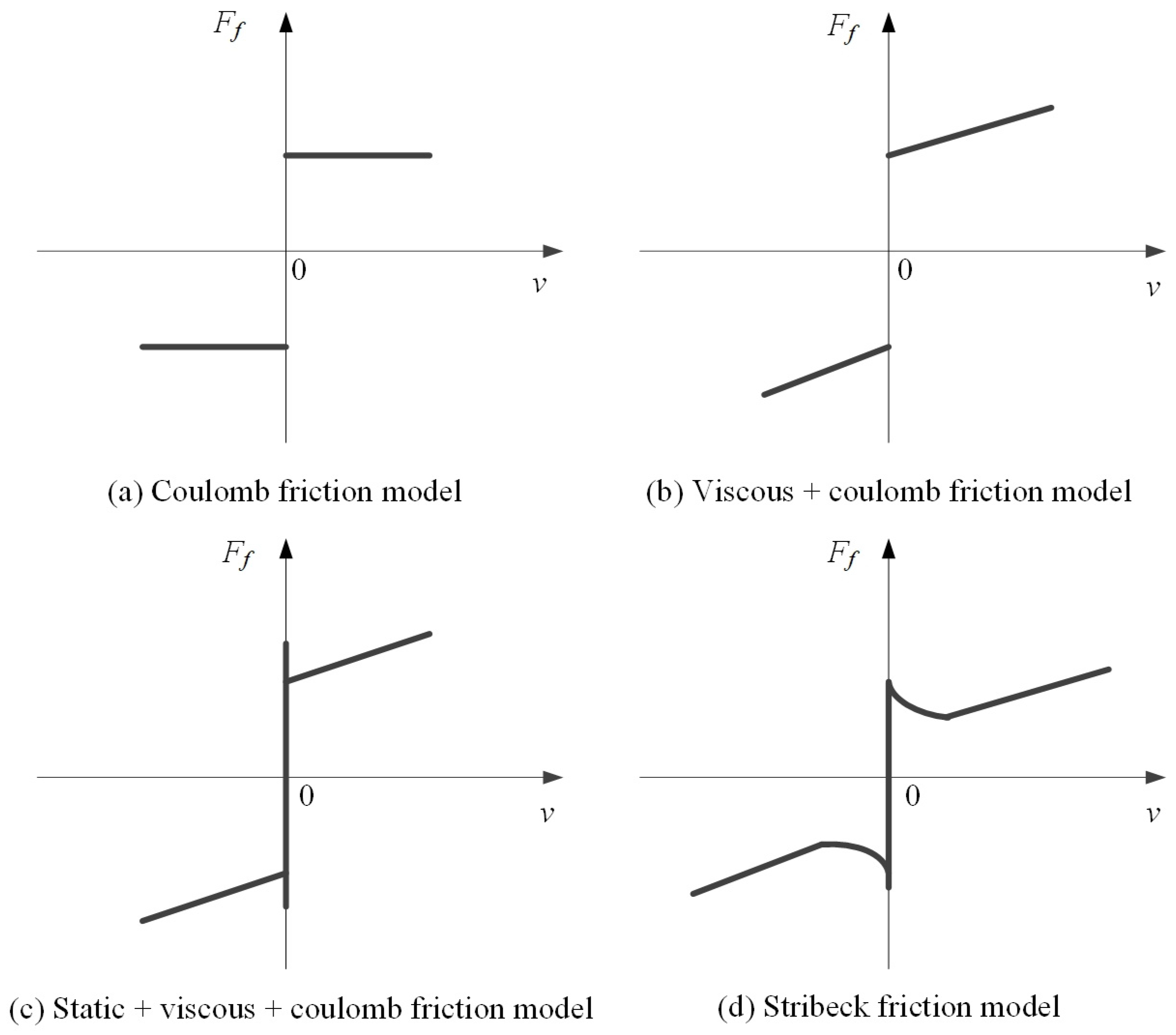
2.2.2. Modelling of Friction
- fv is the viscous friction coefficient (N∙s/m);
- fe is the external force (N);
- fs is the maximum static friction force (N);
- fc is the Coulomb friction force (N).
2.2.3. Modelling of Backlash
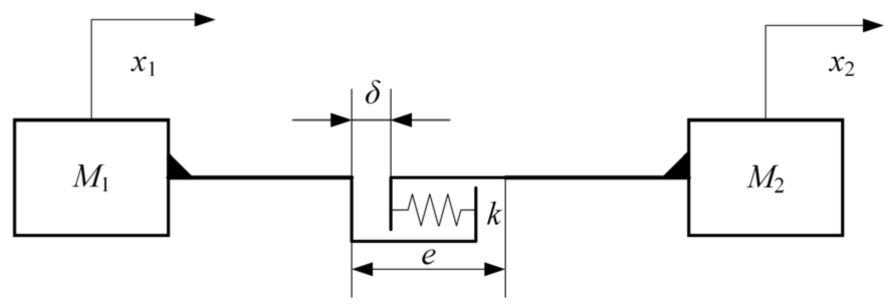
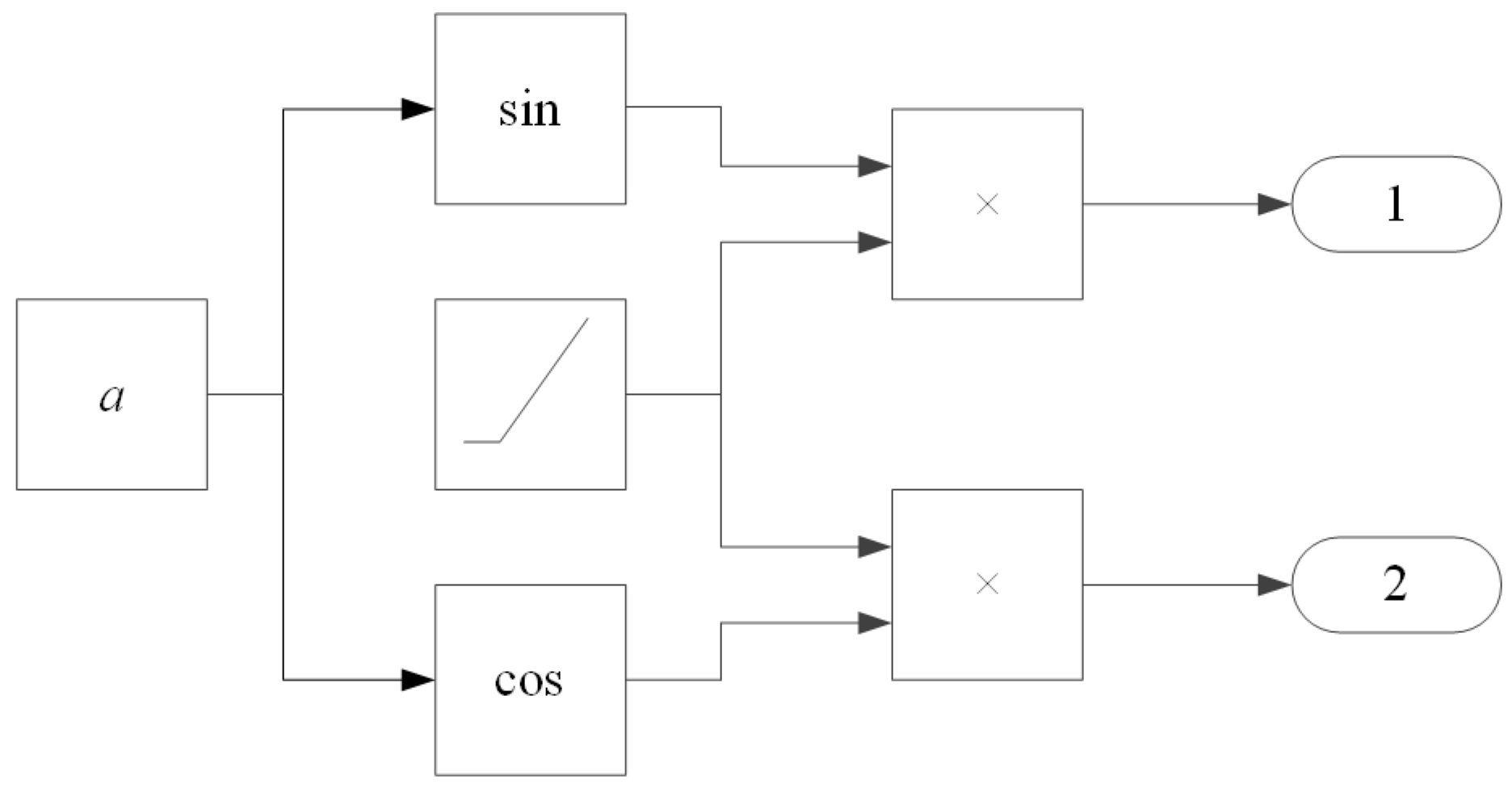
2.2.4. Lateral Shift Model
- F
- is the gravitational force exerted by the tool holder, ram, and slide (N);
- EI
- is the bending stiffness of the beam (N/m);
- l
- is the total length of the beam (m);
- x
- is the distance from the calculation point to the left end of the beam (m).
3. Analysis of the Factors Influencing Servo Error in Heavy-Duty Vertical Machining Centres
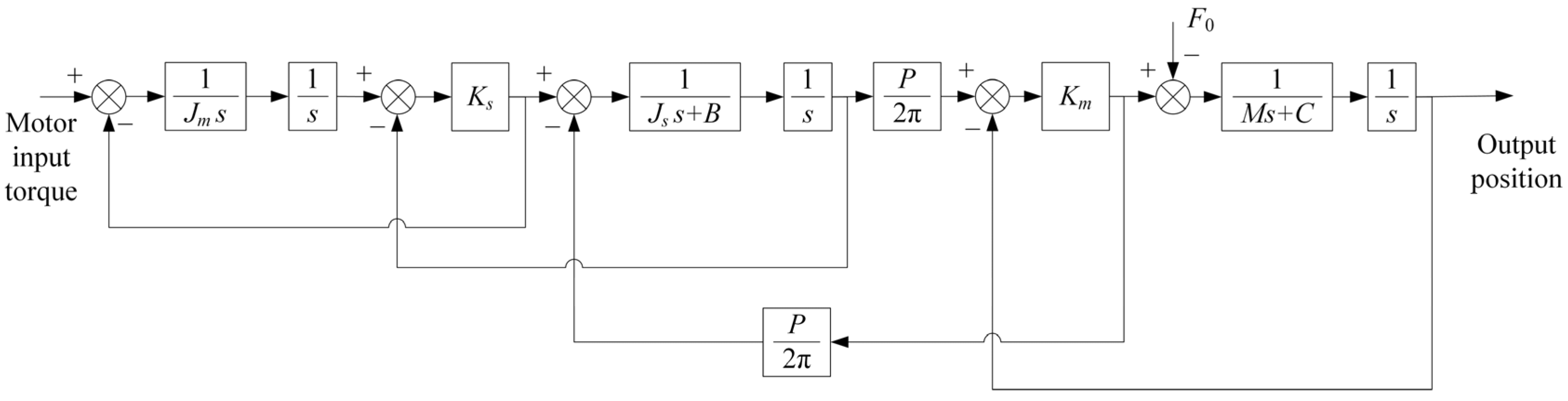
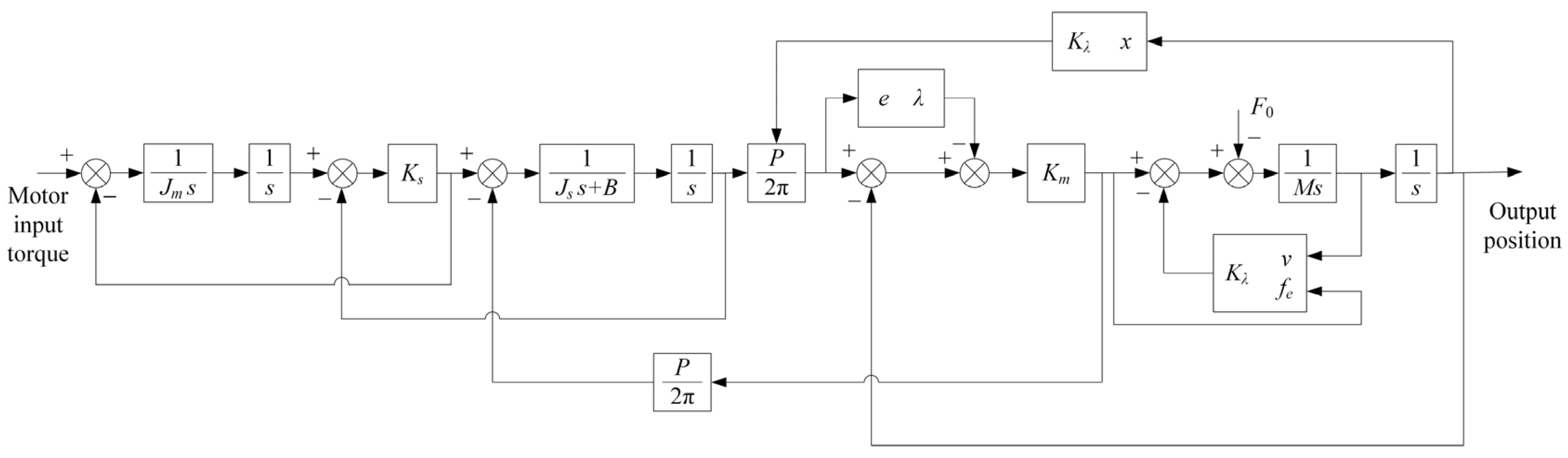
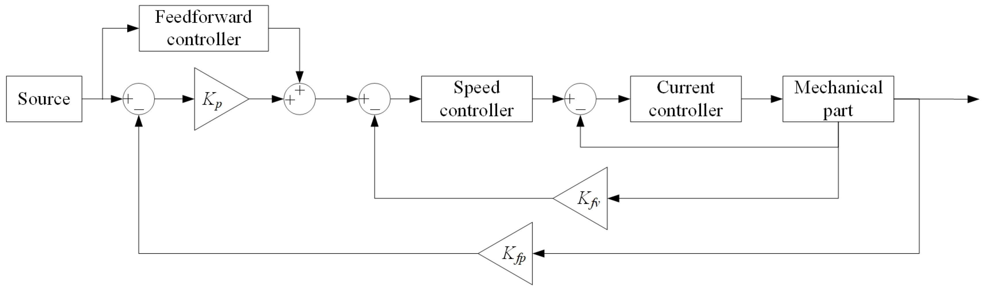
3.1. Simulation Module of a Closed-Loop Servo Feed System
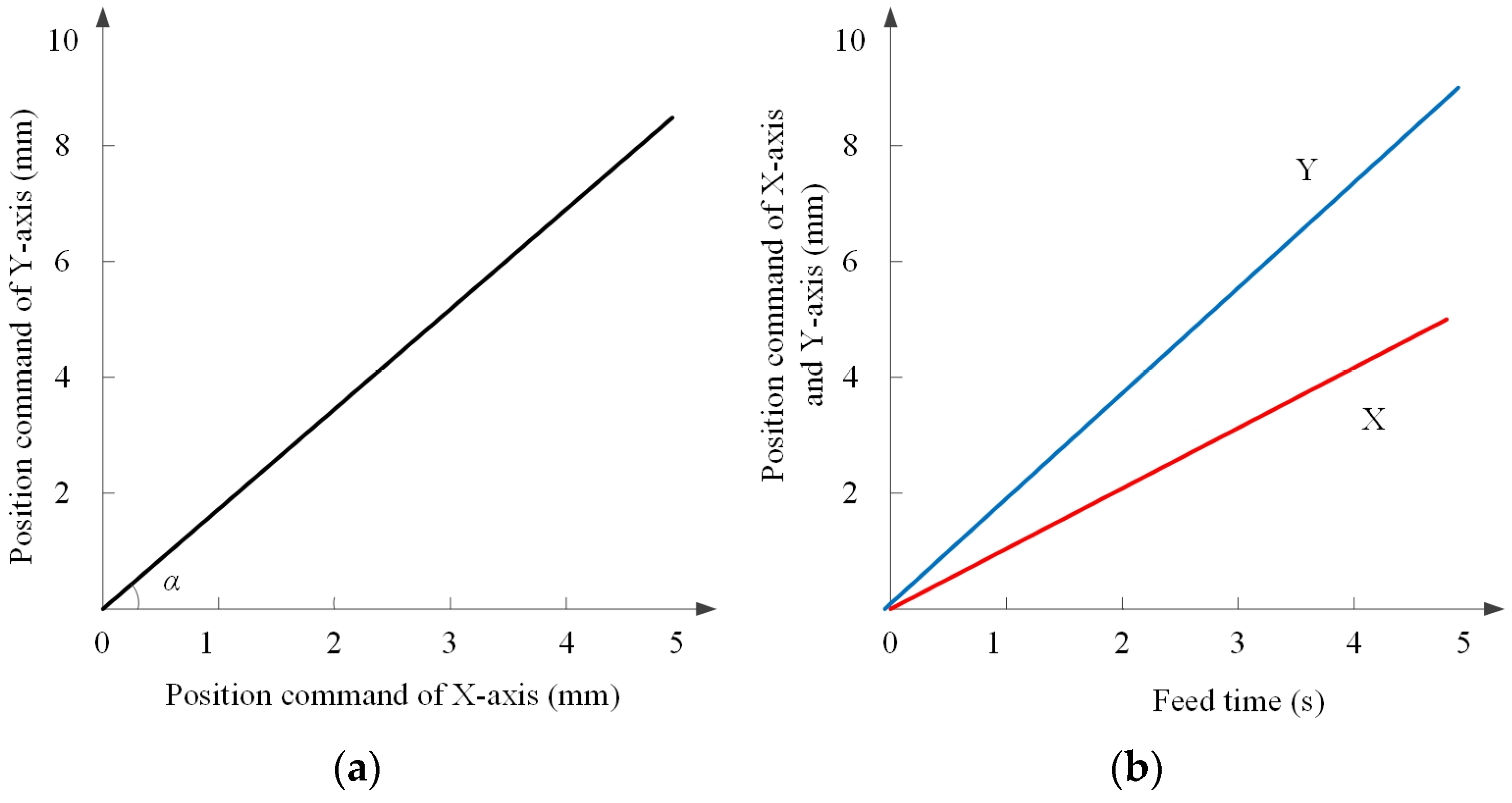
3.1.1. Input Command Design
3.1.2. Simulation Model of Servo Feed System
3.2. Simulation and Analysis of Factors Affecting Servo Error
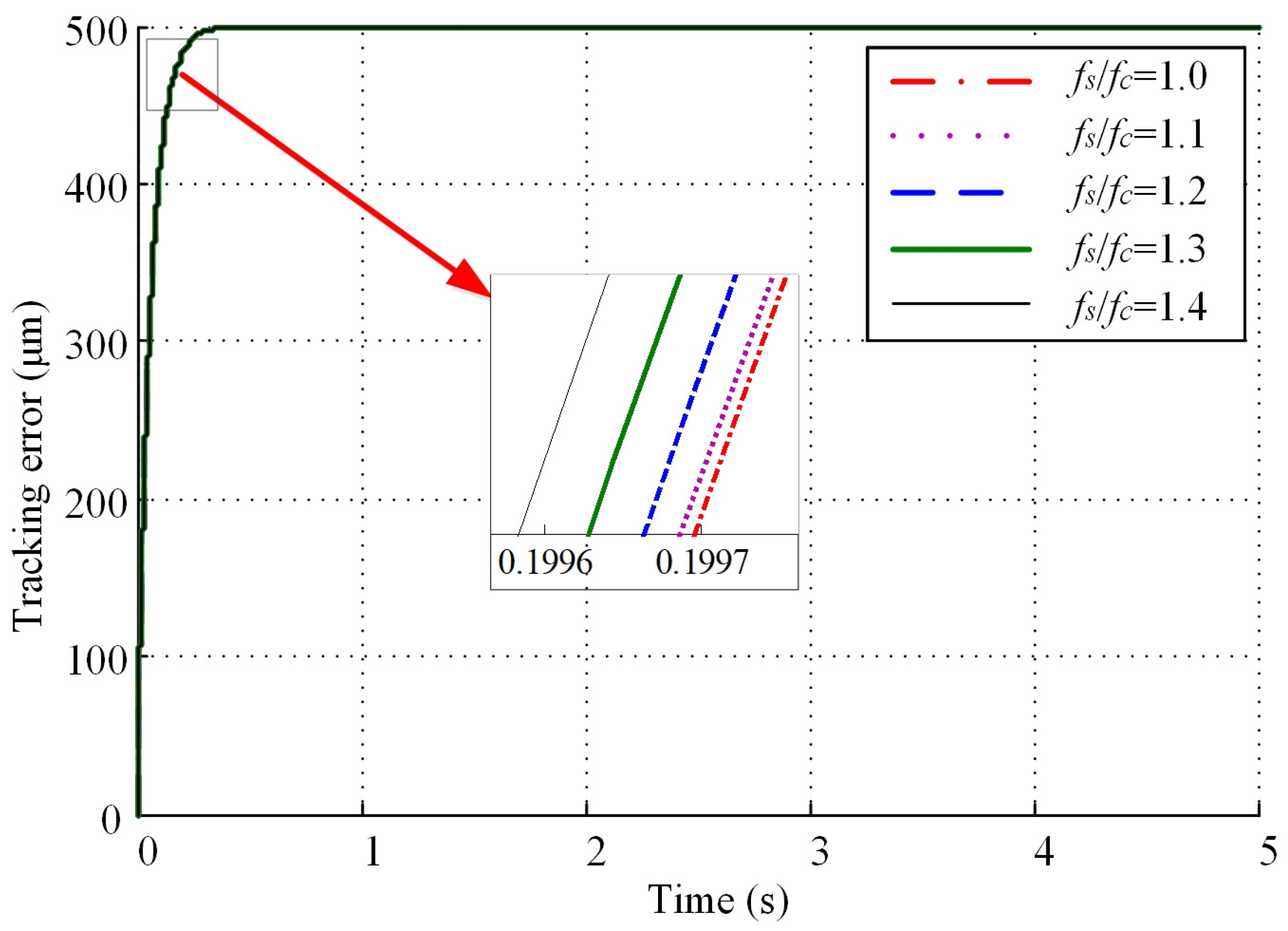
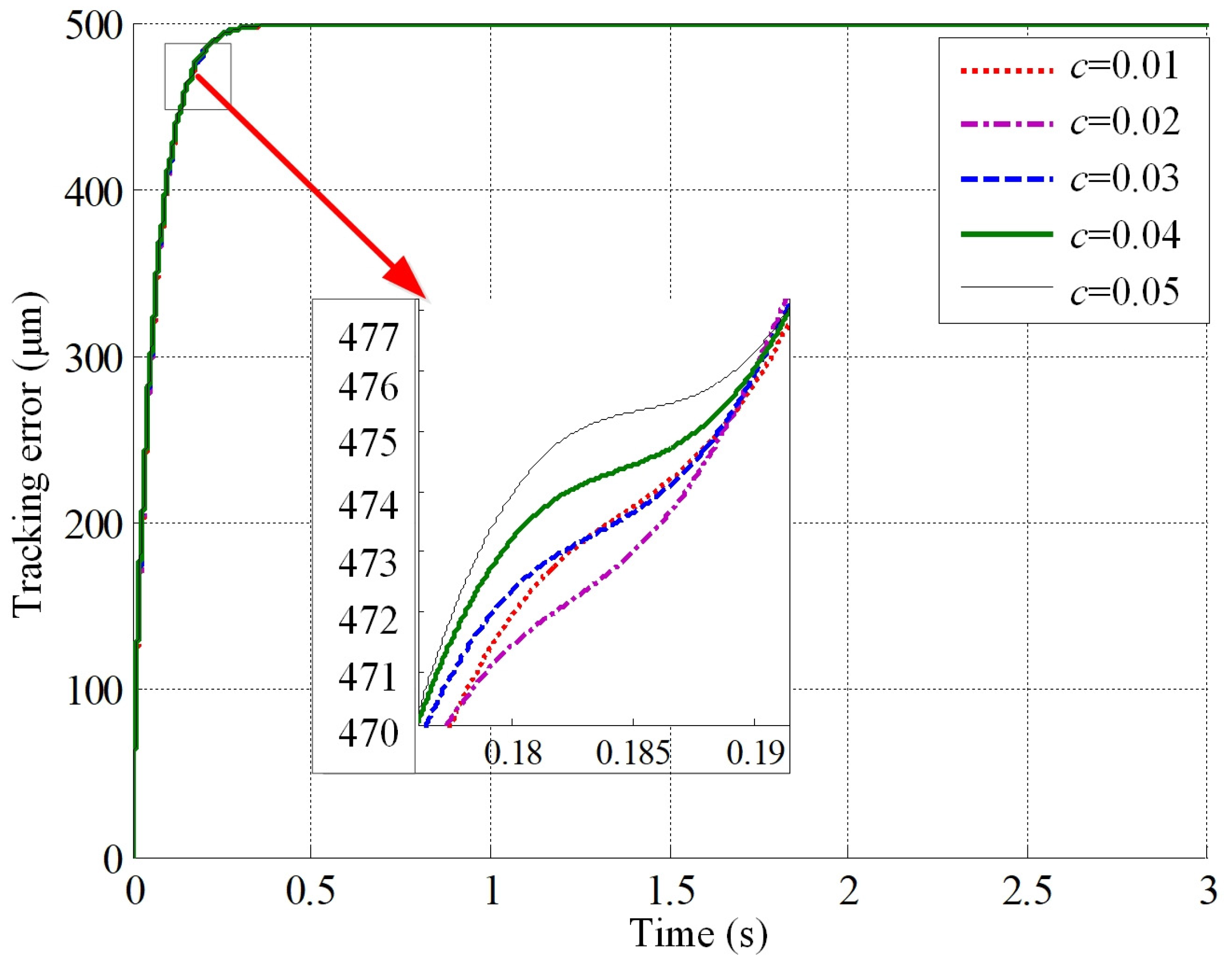
3.2.1. Simulation and Analysis of Nonlinear Factors
- (1)
- The effects of friction force on tracking error
- (a)
- The effect of the static-dynamic friction ratio and Coulomb friction coefficient on the tracking error in the stable state is not significant, mainly during machine tool startup. the larger the static to dynamic friction ratio and Coulomb friction coefficient, the greater the startup tracking error and the longer the startup.
- (b)
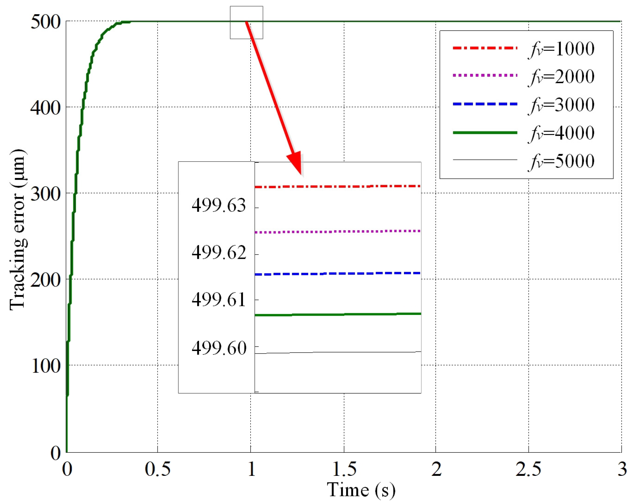
- The changes in viscous friction coefficient have little effect on the tracking error.
- (2)
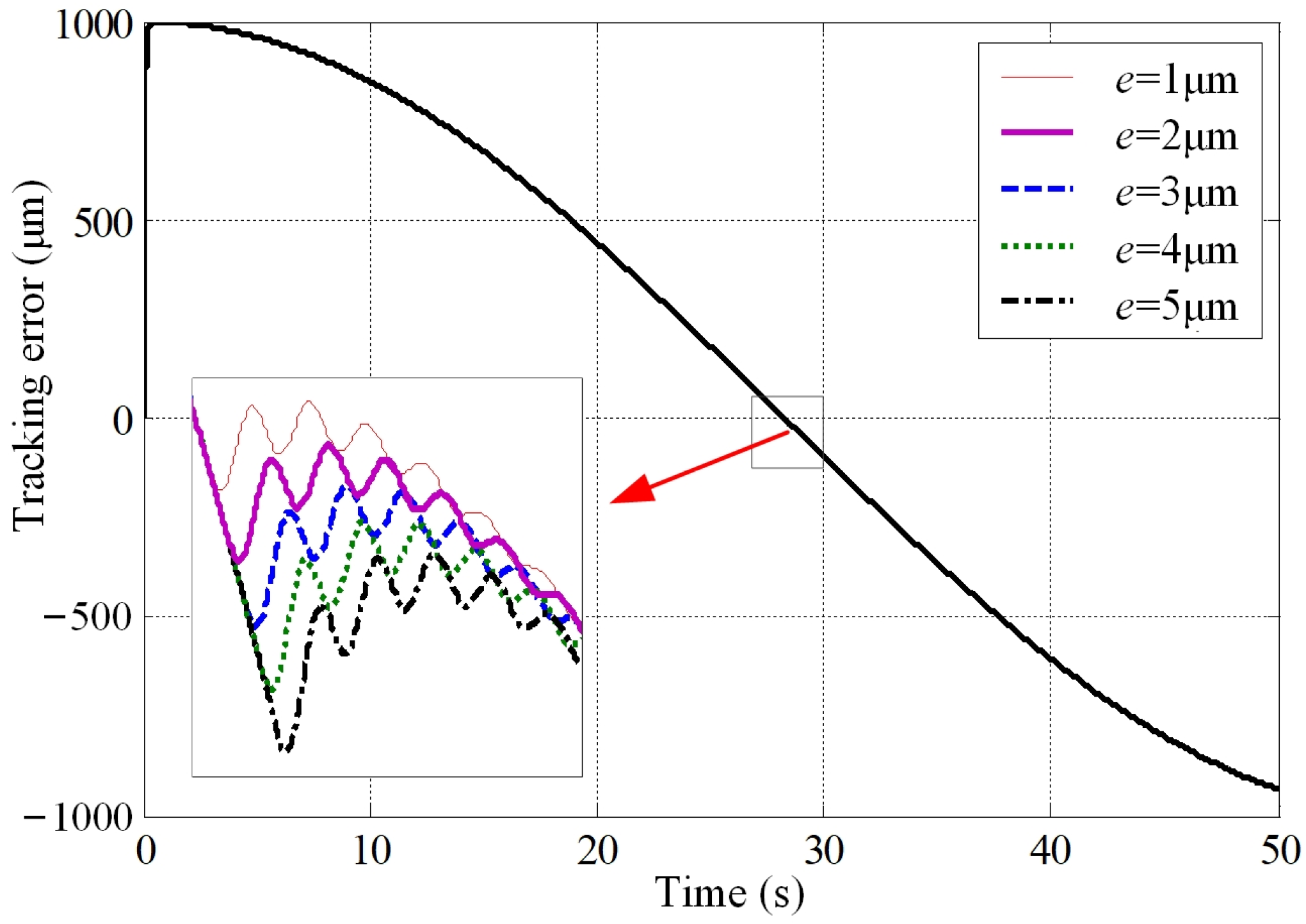
- The influence of backlash on tracking error
- (3)
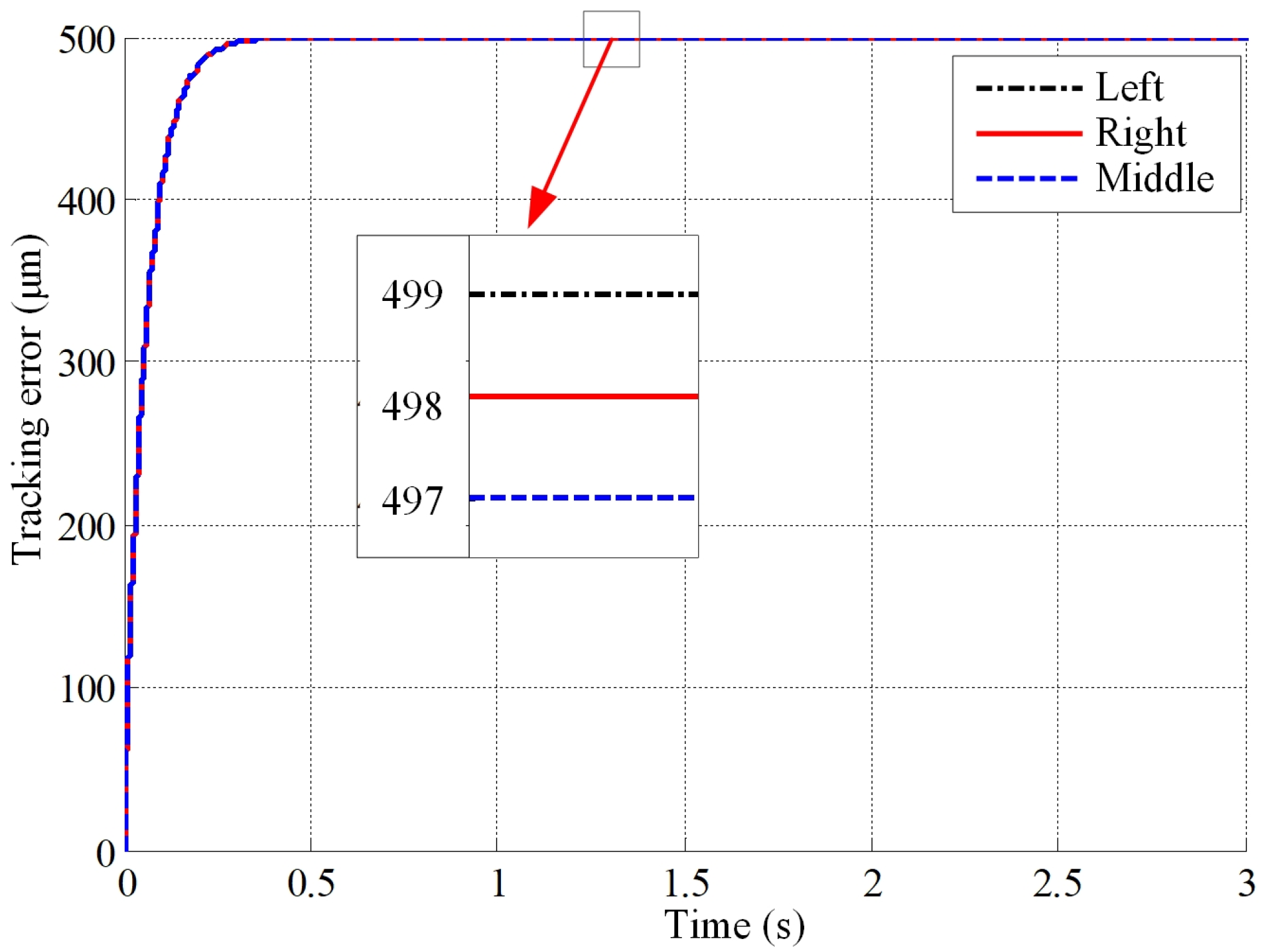
- Influence of lateral shift on tracking error
3.2.2. Simulation and Analysis of Linear Factors
- (1)
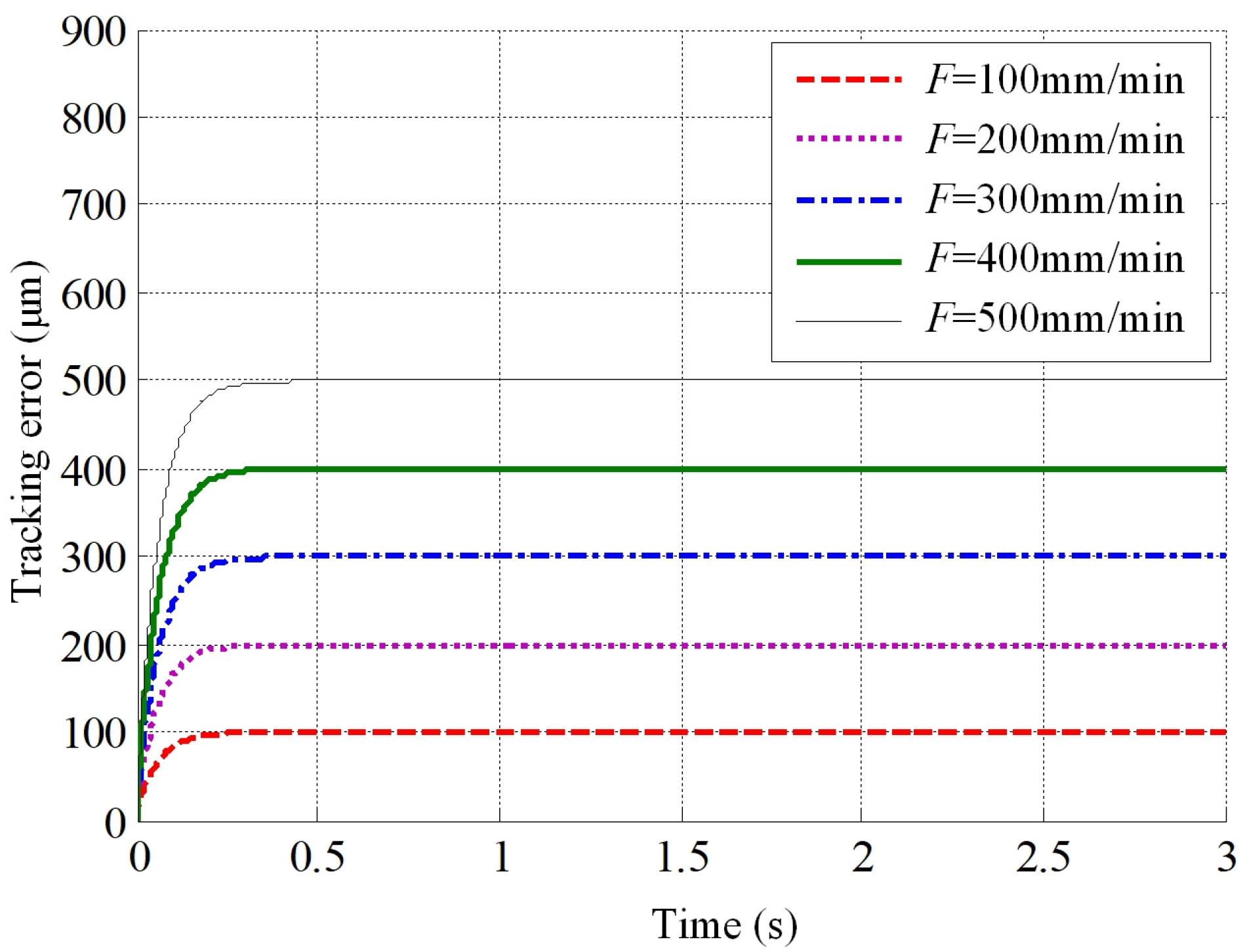
- The influence of different inputs on tracking error
- (2)
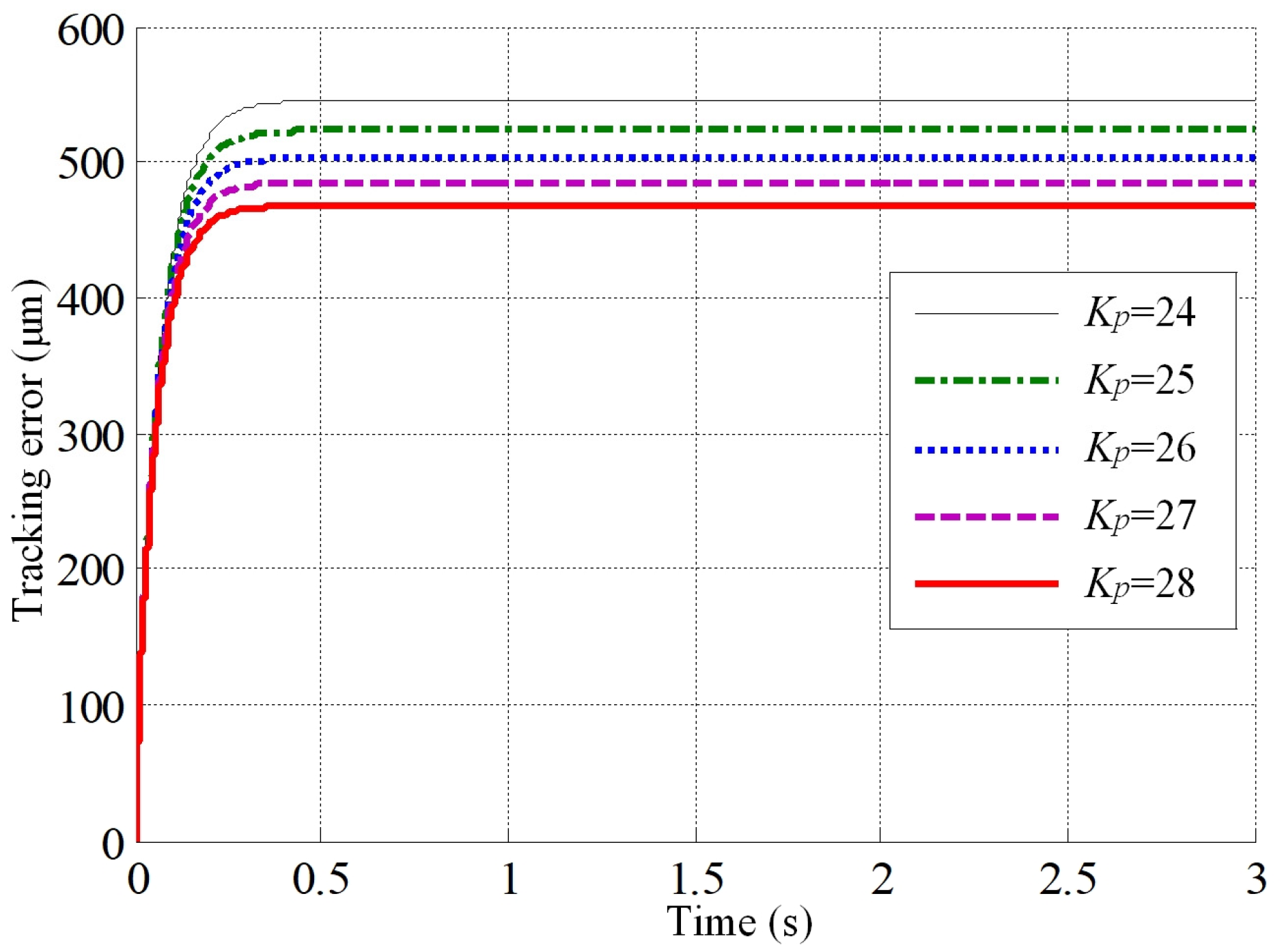
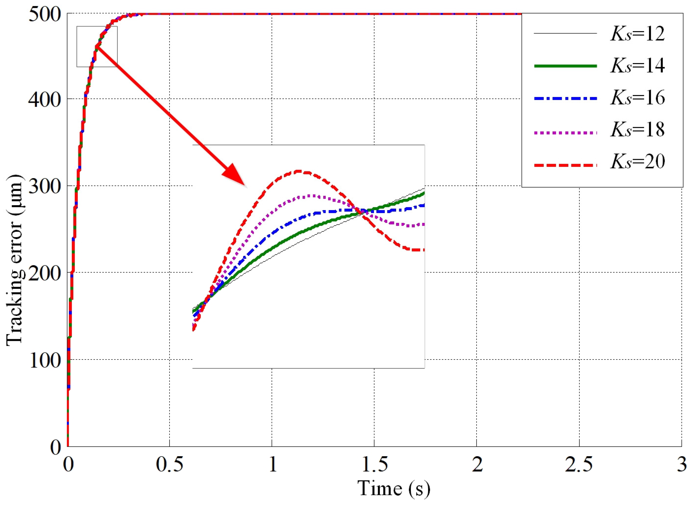
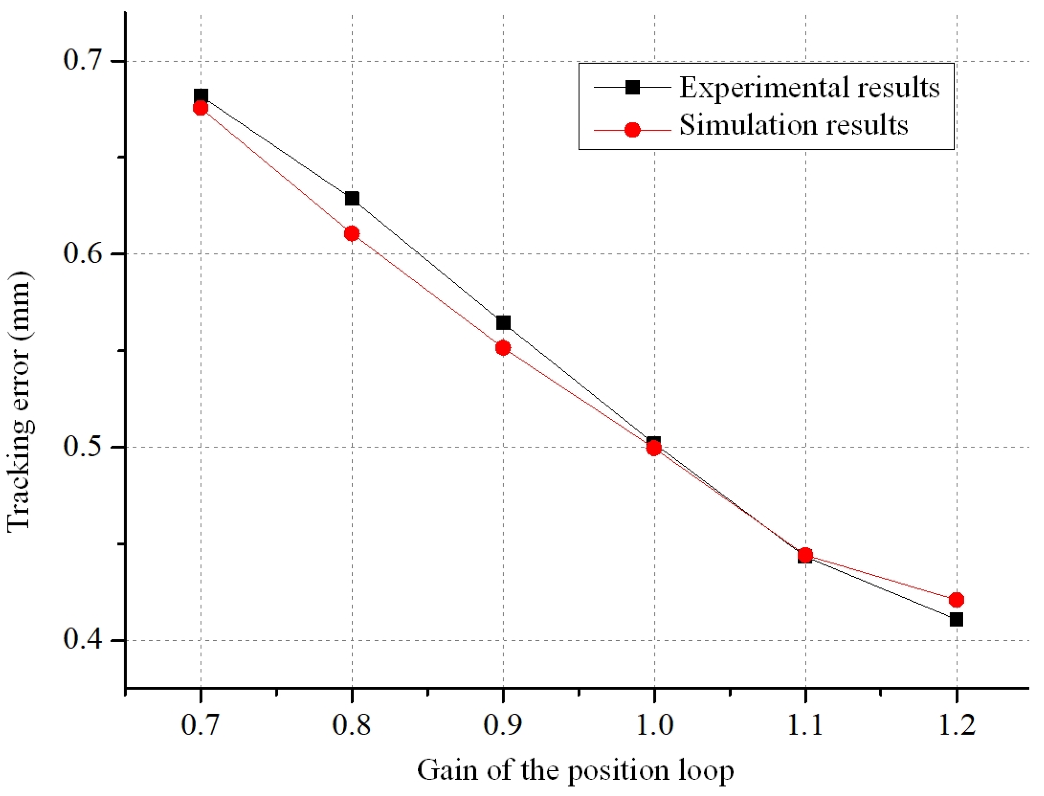
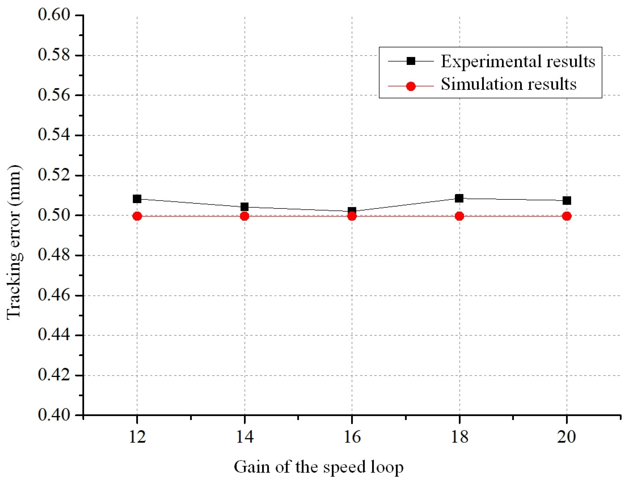
- Effect of different gains on tracking error
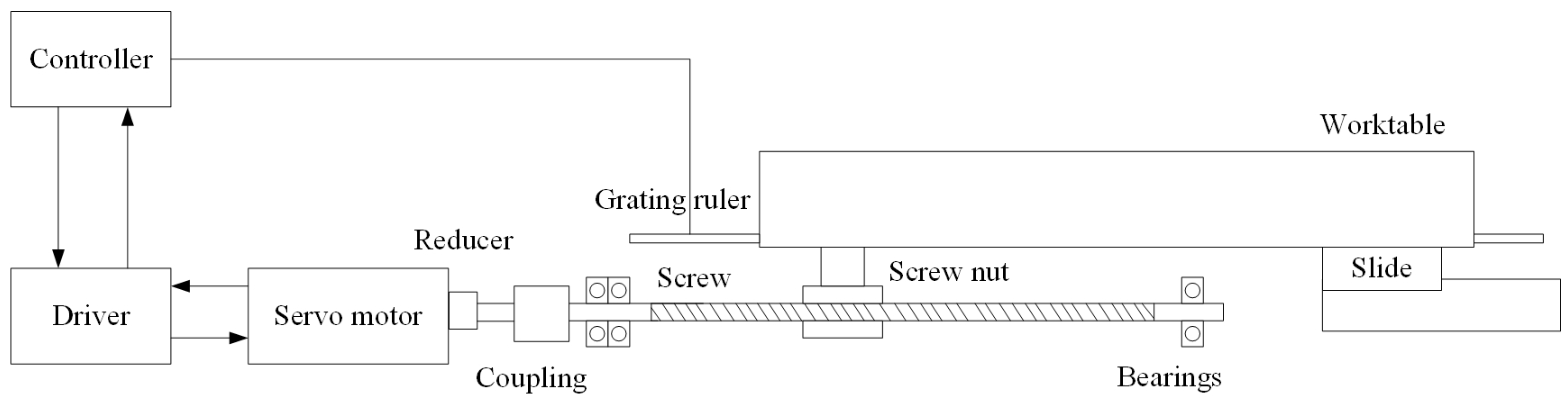
4. Experimental Verification of the Servo Feed System Model for Heavy Vertical Machining Centres
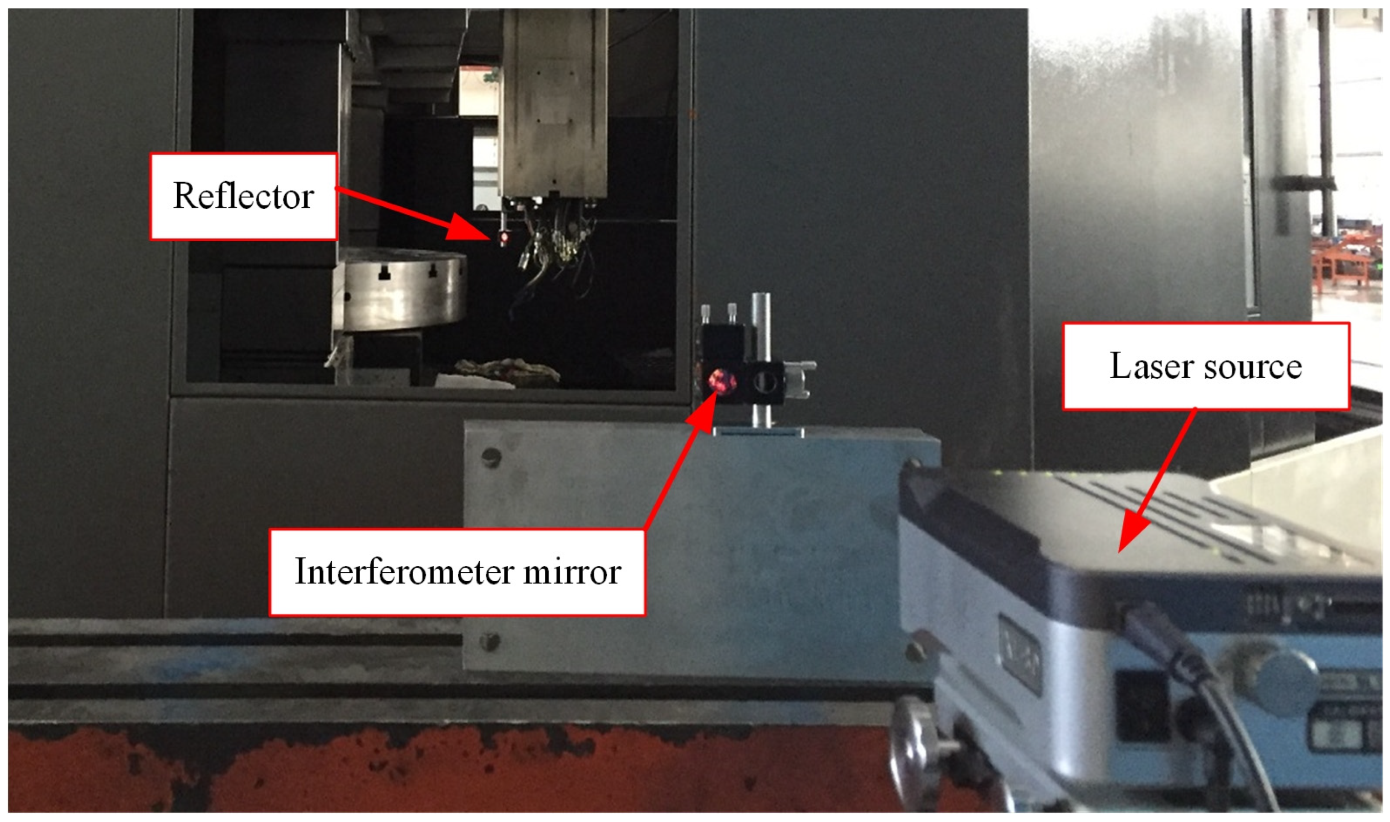
4.1. Experimental Setup
4.2. Experimental Verification of the Theoretical Model of the Servo Feed System
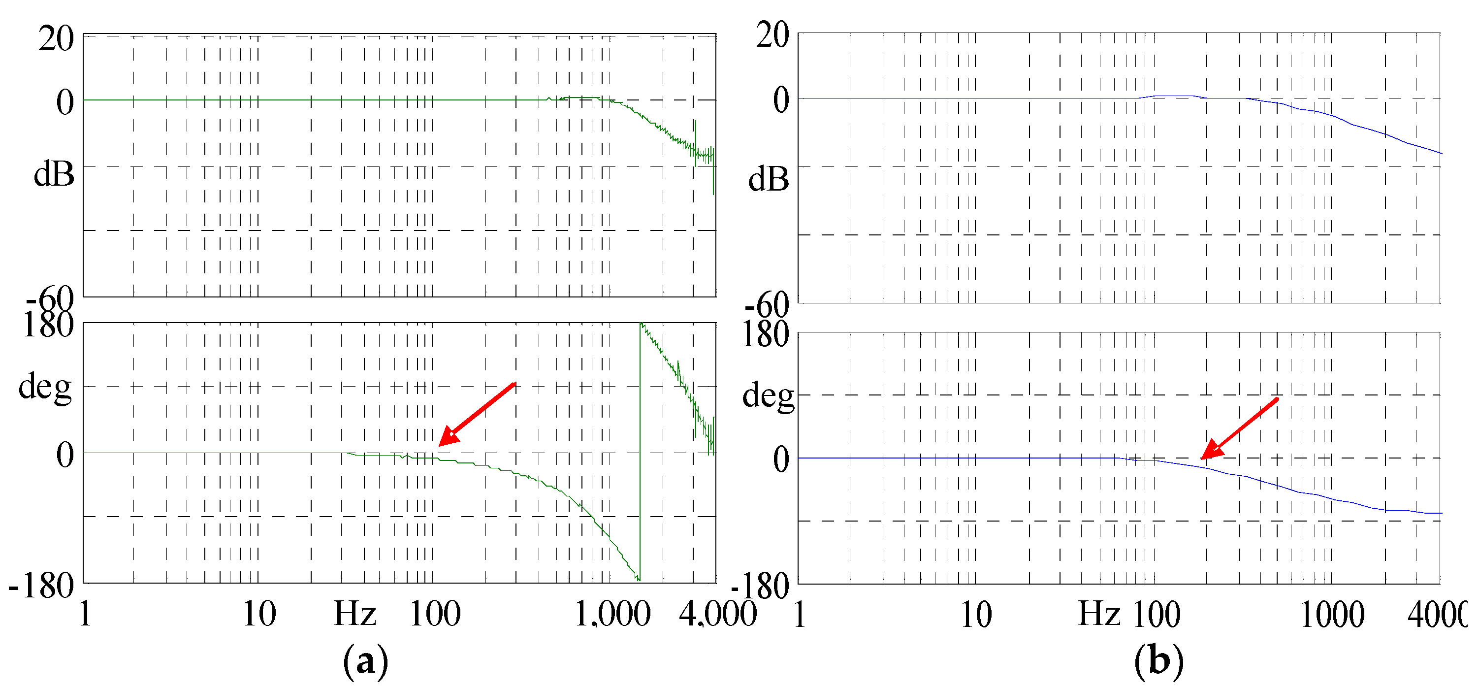
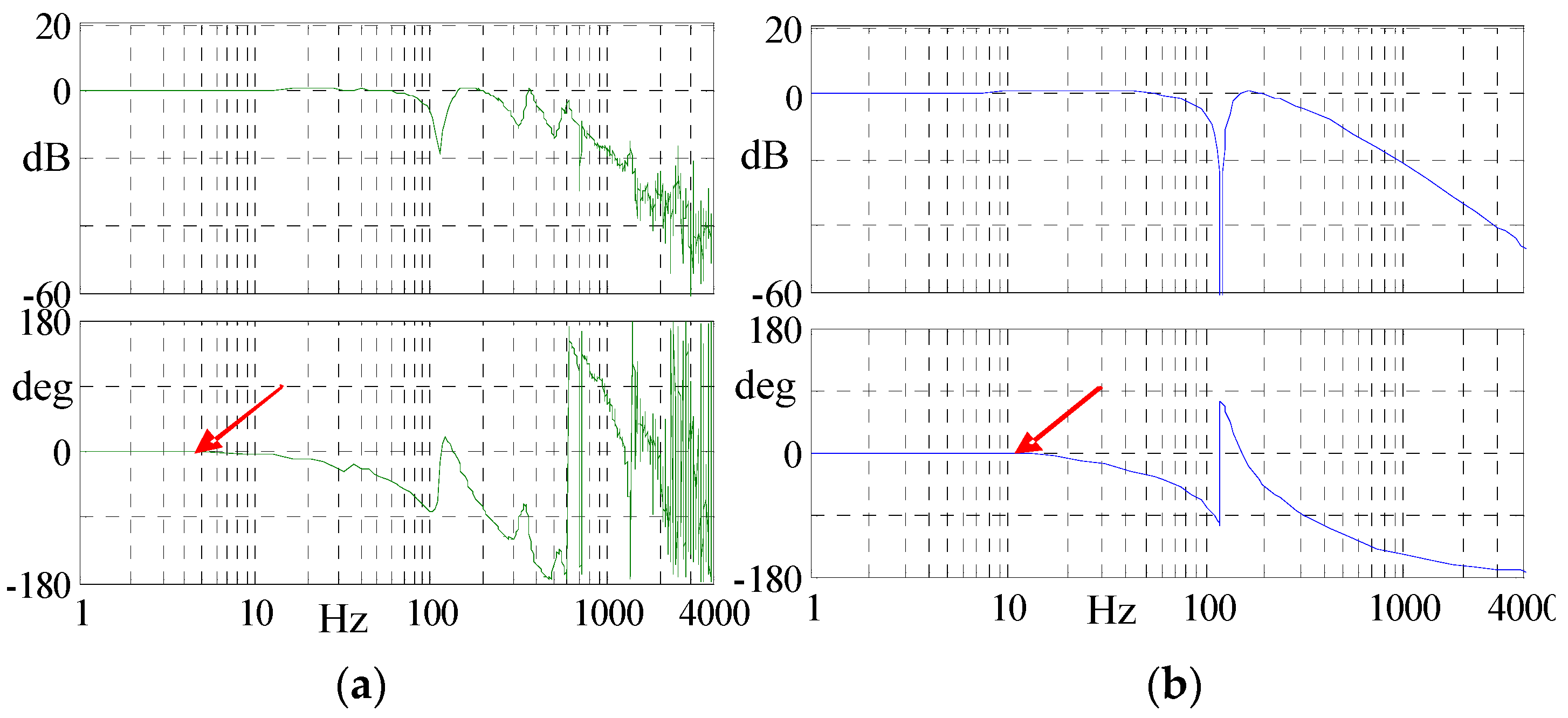
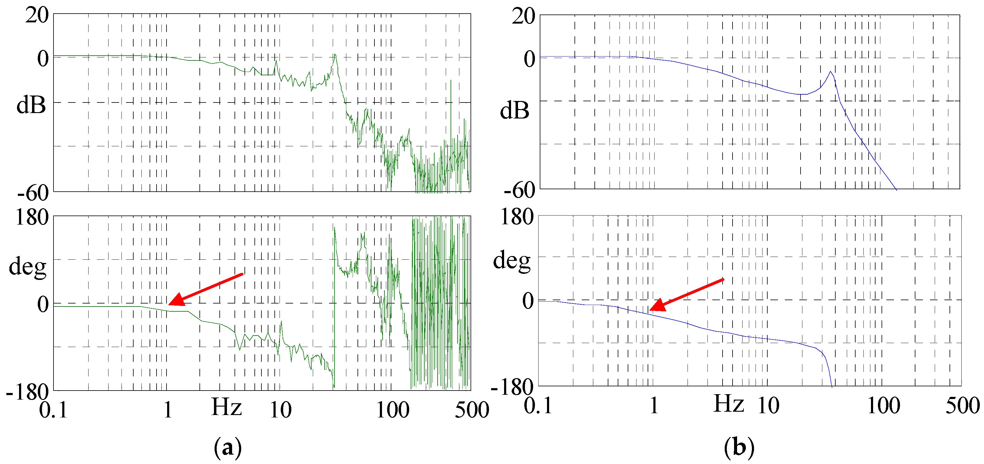
4.2.1. Verification of the Theoretical Model of the Servo Drive System
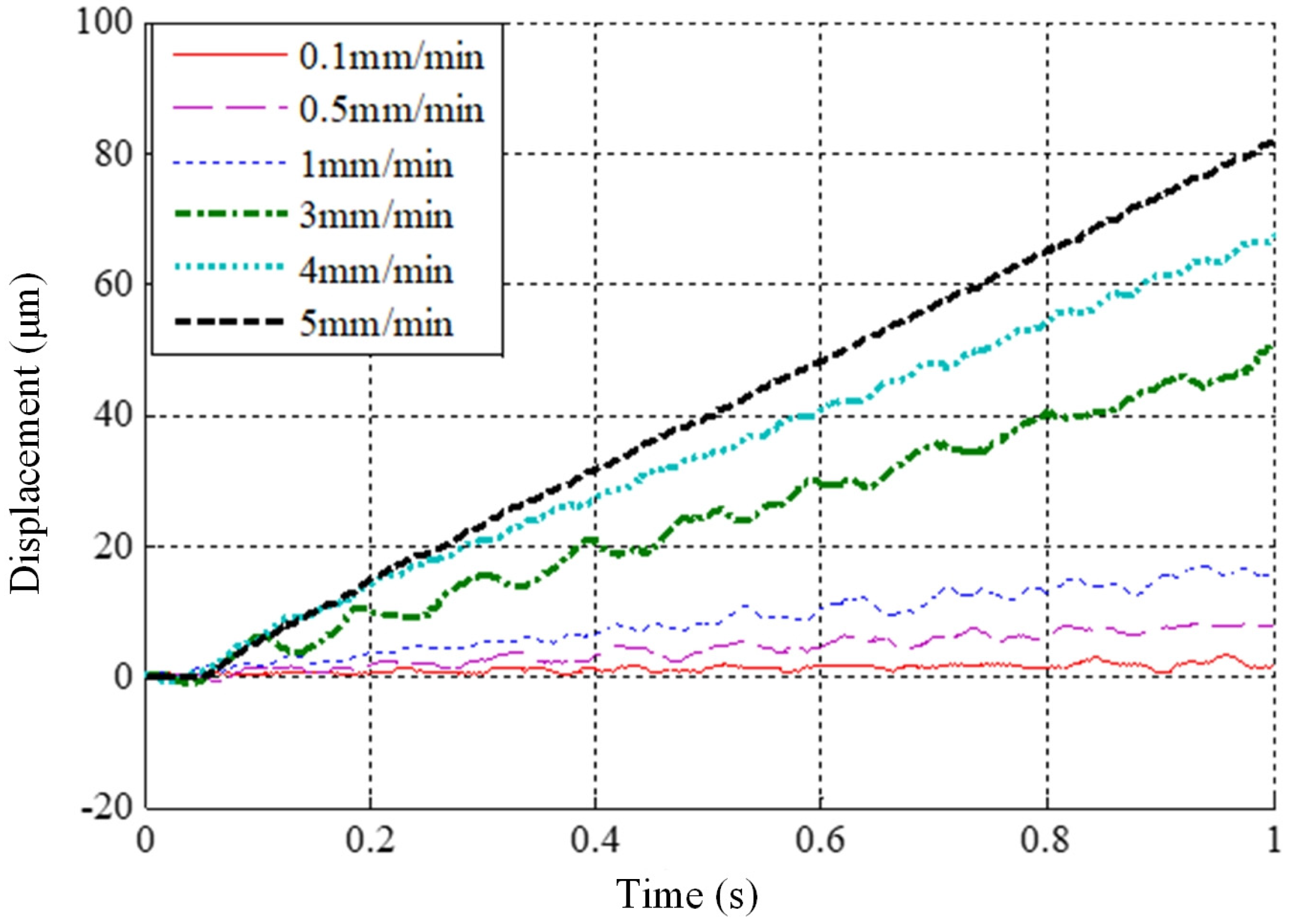
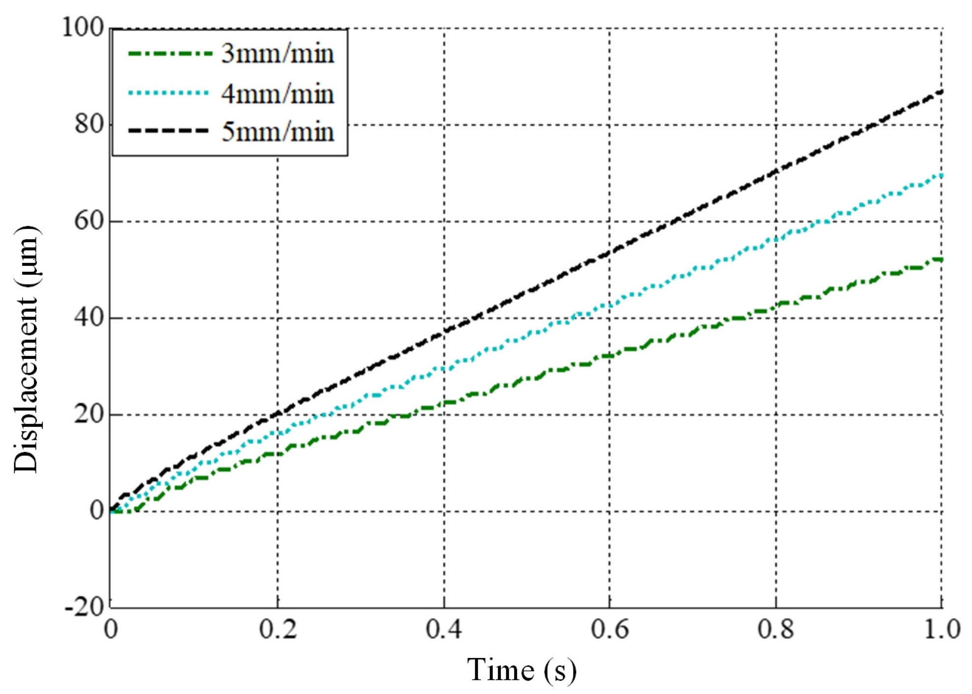
4.2.2. Verification of Critical Stick-Slip Velocity
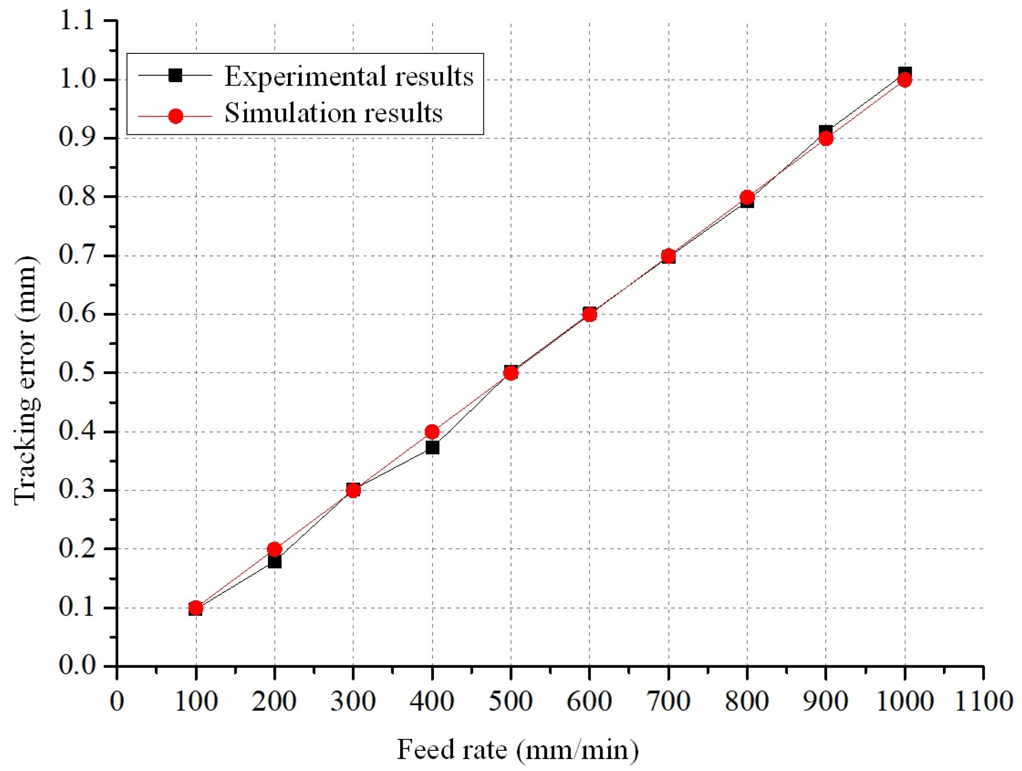
4.2.3. Tracking Error for Linear Motion of X-Axis
5. Conclusions
- (1)
- A theoretical model of the servo feed system for heavy-duty vertical machining centres was created. The model takes into account the characteristics of large mass, large load, and large travel distance, and consists of the servo drive system model and the mechanical transmission system model. The servo drive system model adopts a three-loop control structure commonly used in commercial CNC systems, such as Siemens, FANUC, HEIDENHAIN. The mechanical transmission system model encompasses non-linear aspects such as friction, backlash, and lateral shifts.
- (2)
- The Simulink simulation model for the theoretical servo feed system was established and, through simulations, it was determined that larger backlash, greater offset of the tool holder from the beam centre, and higher feed rates lead to larger tracking errors. Moreover, there exists a positive correlation between tracking error and feed rate. Larger position loop gains result in smaller tracking errors. The impact of the viscous friction coefficient and the velocity loop gain on the tracking error is minimal and can be ignored. On the other hand, the static-to-dynamic friction ratio and the Coulomb friction coefficient primarily affect tracking errors during machine tool startup.
- (3)
- Experiments have been carried out to validate the developed theoretical models. The comparison of Bode plots between the actual CNC drive system and the theoretical models of the servo drive system, both employing a three-loop structure, indicates the validity of the drive system’s theoretical model. The agreement between the measured critical stick-slip velocity range for the X-axis, and the velocity range obtained from the theoretical model simulation, validates the accuracy of the model of the mechanical transmission system. Through a comparison of measured tracking error and theoretical simulation outcomes for the X-axis in linear motion, the accuracy of the developed servo feed system model is confirmed and the feasibility of analysing dynamic servo errors in real machine tools is demonstrated.
Author Contributions
Funding
Data Availability Statement
Conflicts of Interest
References
- Uriarte, L.; Zatarain, M.; Axinte, D.; Yagüe-Fabra, J.; Ihlenfeldt, S.; Eguia, J.; Olarra, A. Machine tools for large parts. CIRP Ann.-Manuf. Technol. 2013, 62, 731–750. [Google Scholar] [CrossRef]
- Andolfatto, L.; Lavernhe, S.; Mayer, J.R.R. Evaluation of servo, geometric and dynamic error sources on five-axis high-speed machine tool. Int. J. Mach. Tools Manuf. 2011, 51, 787–796. [Google Scholar] [CrossRef]
- Bringmann, B.; Maglie, P. A method for direct evaluation of the dynamic 3D path accuracy of NC machine tools. CIRP Ann.-Manuf. Technol. 2009, 58, 343–346. [Google Scholar] [CrossRef]
- Jia, Z.; Ma, J.; Song, D.; Wang, F.; Liu, W. A review of contouring-error reduction method in multi-axis CNC machining. Int. J. Mach. Tools Manuf. 2018, 125, 34–54. [Google Scholar] [CrossRef]
- Lyu, D.; Liu, Q.; Liu, H.; Zhao, W. Dynamic error of CNC machine tools: A state-of-the-art review. Int. J. Adv. Manuf. Technol. 2020, 106, 1869–1891. [Google Scholar] [CrossRef]
- Lin, C.-Y.; Luh, Y.-P.; Lin, W.-Z.; Lin, B.-C.; Hung, J.-P. Modeling the static and dynamic behaviors of a large heavy-duty lathe machine under rated loads. Computation 2022, 10, 207. [Google Scholar] [CrossRef]
- Poo, A.N.; Bollinger, J.G.; Younkin, G.W. Dynamic errors in type-I contouring systems. IEEE Trans. Ind. Appl. 1972, 4, 477–484. [Google Scholar] [CrossRef]
- Xi, X.C.; Poo, A.N.; Hong, G.S. Improving contouring gain accuracy by tuning gain for a bi-axial CNC machine. Int. J. Mach. Tools Manuf. 2009, 49, 395–406. [Google Scholar] [CrossRef]
- Koren, Y. Cross-coupled biaxial computer control for manufacturing systems. ASME J. Dyn. Syst. Meas. Control 1980, 102, 265–272. [Google Scholar] [CrossRef]
- Koren, Y.; Lo, C.C. Variable-gain cross-coupling controller for contouring. CIRP Ann.-Manuf. Technol. 1991, 40, 371–374. [Google Scholar] [CrossRef]
- Yeh, S.S.; Hsu, P.L. Estimation of the contouring error vector for the cross-coupled control design. IEEE/ASME Trans. Mechatron. 2022, 7, 44–51. [Google Scholar]
- Peng, C.C.; Chen, C.L. Biaxial contouring control with friction dynamics using a contour index approach. Int. J. Mach. Tools Manuf. 2007, 47, 1542–1555. [Google Scholar] [CrossRef]
- Cheng, M.Y.; Lee, C.C. Motion controller design for contour following tasks based on real-time contour error estimation. IEEE Trans. Ind. Electron. 2007, 54, 1686–1695. [Google Scholar] [CrossRef]
- Yang, J.; Li, Z. A novel contour error estimation for position loop-based cross-coupled control. IEEE Trans. Mechatron. 2011, 16, 643–655. [Google Scholar] [CrossRef]
- Huo, F.; Xi, X.C.; Poo, A.N. Generalized Taylor series expansion for free-form two-dimensional contour error compensation. Int. J. Mach. Tools Manuf. 2012, 53, 91–99. [Google Scholar] [CrossRef]
- Conway, J.R.; Ernesto, C.A.; Farouki, R.T.; Zhang, M. Performance analysis of cross-coupled controllers for CNC machines based upon precise real-time contour error measurement. Int. J. Mach. Tools Manuf. 2012, 52, 30–39. [Google Scholar] [CrossRef]
- Yu, H.; Zhang, L.; Wang, C.; Feng, X. Dynamic characteristics analysis and experimental of differential dual drive servo feed system. Proc. Inst. Mech. Eng. Part C J. Mech. Eng. Sci. 2021, 235, 6737–6751. [Google Scholar] [CrossRef]
- Shi, S.; Lin, J.; Wang, X.; Xu, X. Analysis of the transient backlash error in CNC machine tools with closed loops. Int. J. Mach. Tools Manuf. 2015, 93, 49–60. [Google Scholar] [CrossRef]
- Wan, M.; Dai, J.; Zhang, W.H.; Xiao, Q.B.; Qin, X.B. Adaptive feed-forward friction compensation through developing an asymmetrical dynamic friction model. Mech. Mach. Theory 2022, 170, 104691. [Google Scholar] [CrossRef]
- Yamada, S.; Fujimoto, H. Precise joint torque control method for two-inertia system with backlash using load-side encoder. IEEJ J. Ind. Appl. 2019, 8, 75–83. [Google Scholar] [CrossRef]
- Wang, Z.; Hu, C.; Zhu, Y. Double Taylor expansion-based real-time contouring error estimation for multi-axis motion systems. IEEE Trans. Ind. Electron. 2019, 66, 9490–9499. [Google Scholar] [CrossRef]
- Kim, S. Moment of inertia and friction torque coefficient identification in a servo drive system. IEEE Trans. Ind. Electron. 2018, 66, 60–70. [Google Scholar] [CrossRef]
- Ebrahimi, M.; Whalley, R. Analysis, modeling and simulation of stiffness in machine tool drives. Comput. Ind. Eng. 2000, 38, 93–105. [Google Scholar] [CrossRef]
- Otten, G.; de Vries, T.J.A. Linear motor motion control using a learning feed forward controller. IEEE/ASME Trans. Mechatron. 1997, 2, 179–187. [Google Scholar] [CrossRef]
- Shiau, T.N.; Huang, K.H.; Hsu, W.C. Dynamic response and stability of a rotating ball screw under a moving skew load. J. Chin. Soc. Mech. Eng. Ser. C 2006, 27, 297–305. [Google Scholar]


| Parameter | Value | Parameter | Value |
|---|---|---|---|
| Position loop gain Kp (rad/s/m) | 26.18 × 10³ | Current loop gain Ki (V/A) | 18.431 |
| Position feedback coefficient Kϕ | 1 | Current loop integral time constant Ti (s) | 0.002 |
| Feedforward coefficient kf | 1 | Total rotational inertia of motor rotor and shaft sleeve Jm (kg·m2) | 0.0215 |
| Equivalent inertia of X-axis Ix (kg·m2) | 0 | Torsional stiffness of the elastic body between the two sleeves of the coupling Kθ (N·m·rad−1) | 4 × 10⁷ |
| Velocity loop gain Ks (A·s·rad−1) | 6.84 | ||
| Velocity loop feedback coefficient Kb | 1 | The total rotational inertia of the ball screw and its shaft sleeve Js (kg·m2) | 0.010 |
| Velocity loop time constant Ts (s) | 0.01 | Ball screw lead (m) | 0.016 |
| Motor winding resistance (Ω) | 0.22 | Equivalent connection stiffness between screw nut and ball screw Km (kg·m2) | 3.6 × 10⁸ |
| Motor armature inductance (H) | 4.7 × 10⁻³ | Total mass of worktable and screw MT (kg) | 6000 |
| Torque current coefficient (N·m·A−1) | 2.34 | Transmission ratio itx | 0.25 |
| Current Loop | Velocity Loop | Position Loop | |||
|---|---|---|---|---|---|
| Proportional Gain | Integral Time Constant | Proportional Gain | Integral Time Constant | Proportional Gain | |
| Numerical Control system | 18.14 V/A | 2 ms | 16 N∙m∙s/rad | 10 ms | 1 m/min/mm |
| Simulation Model | 18.14 V/A | 2 ms | 6.84 N∙m∙s/rad | 10 ms | 26.18 rad/s/mm |
| Feed Rate (mm/min) | Measured Tracking Error (mm) | Simulated Tracking Error (mm) |
|---|---|---|
| 100 | 0.0976 | 0.09993 |
| 200 | 0.1792 | 0.19986 |
| 300 | 0.3015 | 0.29979 |
| 400 | 0.3725 | 0.39972 |
| 500 | 0.502 | 0.49965 |
| 600 | 0.6011 | 0.59958 |
| 700 | 0.6977 | 0.69951 |
| 800 | 0.7926 | 0.79944 |
| 900 | 0.9108 | 0.89937 |
| 1000 | 1.0104 | 0.99936 |
| Kp (m/min/mm) | Measured Tracking Error (mm) | Simulated Tracking Error (mm) |
|---|---|---|
| 0.7 | 0.6820 | 0.6757 |
| 0.8 | 0.6288 | 0.6107 |
| 0.9 | 0.5645 | 0.5516 |
| 1 | 0.5020 | 0.4996 |
| 1.1 | 0.4434 | 0.4442 |
| 1.2 | 0.4109 | 0.4210 |
| Ks (N·m·s/rad) | Measured Tracking Error (mm) | Simulated Tracking Error (mm) |
|---|---|---|
| 12 | 0.5083 | 0.49965 |
| 14 | 0.5042 | 0.49965 |
| 16 | 0.502 | 0.49965 |
| 18 | 0.5085 | 0.49965 |
| 20 | 0.5075 | 0.49965 |
Disclaimer/Publisher’s Note: The statements, opinions and data contained in all publications are solely those of the individual author(s) and contributor(s) and not of MDPI and/or the editor(s). MDPI and/or the editor(s) disclaim responsibility for any injury to people or property resulting from any ideas, methods, instructions or products referred to in the content. |
© 2023 by the authors. Licensee MDPI, Basel, Switzerland. This article is an open access article distributed under the terms and conditions of the Creative Commons Attribution (CC BY) license (https://creativecommons.org/licenses/by/4.0/).
Share and Cite
Wang, H.; Li, T.; Sun, X.; Mynors, D.; Wu, T. Modelling and Analysis of Dynamic Servo Error of Heavy Vertical Machining Centre Considering Nonlinear Factors. Processes 2023, 11, 2930. https://doi.org/10.3390/pr11102930
Wang H, Li T, Sun X, Mynors D, Wu T. Modelling and Analysis of Dynamic Servo Error of Heavy Vertical Machining Centre Considering Nonlinear Factors. Processes. 2023; 11(10):2930. https://doi.org/10.3390/pr11102930
Chicago/Turabian StyleWang, Han, Tianjian Li, Xizhi Sun, Diane Mynors, and Tao Wu. 2023. "Modelling and Analysis of Dynamic Servo Error of Heavy Vertical Machining Centre Considering Nonlinear Factors" Processes 11, no. 10: 2930. https://doi.org/10.3390/pr11102930
APA StyleWang, H., Li, T., Sun, X., Mynors, D., & Wu, T. (2023). Modelling and Analysis of Dynamic Servo Error of Heavy Vertical Machining Centre Considering Nonlinear Factors. Processes, 11(10), 2930. https://doi.org/10.3390/pr11102930