Article

Research on Pressure Control of an Electro-Hydraulic Servo System Based on Sliding-Mode Variable-Structure Direct Torque Control

1
Henan Institute of Technology, Xinxiang 453003, China
2
School of Mechanical Engineering, Yanshan University, Qinhuangdao 066004, China
*
Author to whom correspondence should be addressed.
Processes 2023, 11(1), 92; https://doi.org/10.3390/pr11010092
Submission received: 14 November 2022 / Revised: 10 December 2022 / Accepted: 17 December 2022 / Published: 29 December 2022

Abstract

:
Taking a direct-drive volume control (DDVC) electro-hydraulic servo system as the research object and aiming at the problems of the servo motor torque fluctuation, high-precision system pressure control, and dynamic response of the system, based on traditional motor direct torque control (DTC), a motor direct torque control method based on a sliding-mode variable structure is proposed to control the system pressure. The motor torque loop is part of the inner control loop and has a rapid dynamic response speed, resulting in higher pressure control accuracy. A nonlinear mathematical model was established for the DDVC electro-hydraulic servo system. The switch meter hysteresis controller in the traditional DTC system was replaced with space vector pulse-width modulation technology. Then, the PID control module in space vector modulation technology was replaced with high-order sliding-mode variable-structure control. Through the coupling relationship between the electric machine and the constant-displacement pump, the pressure can be controlled with high precision using motor torque control. Finally, using the MATLAB/Simulink simulation platform and the DDVC electro-hydraulic servo system simulation model, the proposed theoretical approach to torque control was verified on the basis of simulations and experiments, and the performance with regard to pressure control in the hydraulic system was observed. The simulation and experimental results show that the designed torque control is able to effectively reduce the motor torque fluctuation and improve the dynamic response characteristics of the system. The system pressure control is superior to traditional pressure control methods based on speed regulation, and it has higher control accuracy and a better dynamic response.

1. Introduction

Electro-hydraulic servo control systems are an important part of hydraulic technologies and are one of the basic technical components of modern control engineering. Depending on their working principle, electro-hydraulic servo systems can be divided into pump control and valve control systems. Traditional electro-hydraulic servo technologies are mainly based on valve control systems. Traditional electro-hydraulic servo valve control systems are widely used in aerospace and automatic industrial production due to their fast dynamic response and high control accuracy, but they also have disadvantages related to high throttling loss and the low use of system energy [1]. Direct-drive volume servo electro-hydraulic servo systems are a form of closed electro-hydraulic servo pump control systems composed of a servo motor, a constant-displacement pump, a hydraulic cylinder, etc. Compared with traditional valve control systems, they have the technical advantages of a high power-to-weight ratio, high integration, high efficiency, energy conservation, environmental friendliness, etc. [2]. Therefore, they are widely favored by engineers and have become a key topic of research and development in the electro-hydraulic servo field. The research on DDVC electro-hydraulic servo systems is relatively mature in the United States, Japan, and other countries and is based on a wealth of experience in practical applications and the provision of considerable economic benefits [3,4]. Japanese companies such as Mitsubishi, Kawasaki, and Buoyue have made fruitful research achievements with respect to the efficiency, energy savings, compactness of the configuration, noise reduction, and other aspects of DDVC systems, and DDVC systems have been widely applied in the precision industry. The American MOOG Company used EHA actuators for flight tests and performance simulations of various types of aircraft and flight simulators and achieved certain success; therefore, they have gradually begun to be used in practice [5]. With the continuous development of electro-hydraulic servo technology, its applications are becoming increasingly extensive, and the requirements in terms of the control accuracy and dynamic response characteristics of electro-hydraulic servo pump control systems are becoming increasingly high. Improving the dynamic response characteristics of the system is the key research direction of the current DDVC electro-hydraulic servo system [6,7,8,9,10].
In view of the uncertainty and nonlinearity of accurate and efficient hydraulic actuators, Dang Xuan Ba et al. proposed a control method for integrated model inversion controllers for the position-tracking control of pump-controlled electro-hydraulic systems. Inversion technology was used to compensate for the nonlinearity and unknown aspects of the system. At the same time, a new identification method based on this model was used to better deal with the uncertainty of the system. This method exhibited improved robustness and adaptability [11]. Quoc Dong Hoang et al. proposed a variable integral sliding-mode control structure with a disturbance observer based on the super-twisting algorithm to solve the problem of system instability under conditions of transient-state and control performance degradation due to complex disturbances. It was not only able to overcome the extreme sensitivity of the system when moving rapidly but also eliminated the uncertainty of the system’s internal parameters and the interference caused by external loads when tracking the acceleration of the fast gain plan [12]. Guihai Luo and Daniel Gorges proposed an adaptive robust force control method for pump-controlled electro-hydraulic actuators used in active suspension systems. Aiming to address the limitations of the existing linear model of pump-controlled electro-hydraulic actuators, an improved nonlinear model was proposed. An adaptive robust control method based on a linear tracking differentiator was proposed to deal with parameter uncertainty and unknown nonlinear dynamics [13]. Bobo Helian et al. designed an ARC backstepping controller for pump-controlled electro-hydraulic systems. To achieve the accurate tracking of the target trajectory, an adaptive robust control strategy based on nonlinear dynamics and uncertain parameters was adopted to design the controller. This control method can achieve high-precision motion control under the condition of nonlinearity and the uncertainty of the hydraulic system [14]. Zheng Zhang et al. proposed a double fuzzy sliding mode control method based on feedback linearization optimal sliding mode surface, which further improved the response speed and control accuracy [15].
Kou Farong et al., from Xi’an University of Science and Technology, analyzed the motor principle and proposed a current controller based on the inner loop of the motor speed to realize force tracking, control the law of influence on system force, and improve the dynamic characteristics of the electro-hydraulic servo pump control system [16]. Gu et al., from Chang’an University, analyzed the coupling mechanism of multiple energy domain parameters of the electromechanical hydraulic system under the combined action of load conditions and power sources in view of the problem of strong nonlinear coupling within the electromechanical hydraulic system. On the basis of the established internal coupling effect chain of mechanical, electrical, and hydraulic subsystems, the authors proposed a kinetic energy stiffness analysis method for electromechanical hydraulic systems, and they revealed the change law of the kinetic energy stiffness of the system under the action of variable parameters of multiple sources [17]. Guo et al., from the Taiyuan University of Technology, proposed a sliding-mode position-tracking control strategy based on an extended state observer for the dynamic response performance and servo accuracy of electro-hydraulic servo pump control systems [18]. Jiang et al., from the Harbin Institute of Technology, designed a discrete sliding-mode controller using the exponential approach law to solve the dead zone and nonlinear characteristics of the force control of an electro-hydraulic servo pump control system, significantly improving the control performance of the DDVC system [19].
For the pressure control of electro-hydraulic servo pump control systems, considering that the motor torque loop belongs to the inner control loop, with a fast dynamic response and more direct pressure control, this study used the motor torque mode to control the output pressure of the pump control system. The hydraulic components and internal torque drive unit of a torque direct-drive pump control system were studied, a torque direct-drive pump control system framework was built, and the mathematical model of the hydraulic system was deduced and analyzed. Considering the high-performance pressure control requirements of the system, the torque control method of the servo motor was optimized using the sliding-mode control algorithm.

2. Principle of the DDVC Electro-Hydraulic Servo System

The DDVC electro-hydraulic servo system adopts an integrated design consisting of a servo motor, a constant-displacement pump, and a hydraulic cylinder, which has the advantages of high integration, a high power–weight ratio, and a good energy-saving effect. A schematic diagram of the DDVC electro-hydraulic servo system is shown in Figure 1 [20].
The DDVC electro-hydraulic servo system uses a servo motor to drive a constant-displacement pump. Both ends of the pump are directly connected to both ends of the hydraulic cylinder. Compared with the traditional valve control system, this reduces the flow loss caused by the valve while having a higher energy use rate. The accumulator and one-way valve work together to replenish the oil in the system. The overflow valve maintains the system pressure within the safe value range to ensure system safety. The controller outputs the command to control the torque and speed of the servo motor, adjusts the flow required in the system through the torque and speed, and then controls the displacement, speed, force, etc., of the hydraulic cylinder.
In this paper, the principle of motor direct torque control is used to control the pressure of hydraulic systems with high accuracy. Traditional motor direct torque control uses a Bang–Bang controller composed of two hysteresis modules controlling the torque and flux amplitude, respectively. This presents issues such as high flux and torque ripple, an inconstant inverter switching frequency, and high-frequency noise caused by torque ripple. To address these problems and improve the dynamic quality of the motor torque control system, this study first used space vector modulation technology to solve the problem of the instability of inverter switching and then used the advantages of sliding-mode control, such as its insensitivity to disturbances and parameters and its fast response speed, to optimize the motor torque control algorithm to improve the robustness and control performance of the system. The final control principle is shown in Figure 2.

3. Mathematical Model of the DDVC Electro-Hydraulic Servo System

3.1. Mathematical Model of the Servo Motor

The structure of the servo motor is complex. Without changing the basic functions of the servo motor system, some complicated nonlinear factors that have little influence on the system are ignored. In order to establish the mathematical model of the servo motor, the mathematical model in the synchronous rotation d-q coordinate system is usually selected. The specific analysis process is as follows.
Stator flux equation:
ψ d = L d i d + ψ f ψ q = L q i q
Stator voltage equation:
U d = R s i d + d d t ψ d ω e ψ q U q = R s i q + d d t ψ q + ω e ψ d
We substitute the stator flux formula in Equation (1) into the stator voltage equation, which can be converted into:
U d = R s i d + L d d d t i d ω e L q i q U q = R s i q + L q d d t i q + ω e ( L d i d + ψ f )
Electromagnetic torque equation:
T e = 3 2 p n ψ f i q + L d L q i d i q
Equation of motion:
T e T L = J L d ω m d t + B m ω m
where ψ d , ψ q are the d-q axis components of the stator flux, L d , L q are d-q axis equivalent inductances of stator inductance, i d , i q are d-q axis components of the stator current, ψ f is the permanent magnet flux linkage, U d , U q are the d-q axis components of the stator voltage, R s is the stator resistance, ω e is the electrical angular velocity, T e is the internal electromagnetic torque, P n is the polar logarithm, T L is the load torque, J L is the total moment of inertia converted to the axis of rotation, ω m is the mechanical angular speed of the motor, and B m is the motor damping coefficient.
By means of coordinate conversion, the current components of the d-axis and q-axis of the stator current are converted into Equation (6):
i α i β = 2 3 1 1 2 1 2 0 3 2 3 2 i a i b i c
The inverse transformation equation is:
i a i b i c = 2 3 1 0 1 2 3 2 1 2 3 2 i α i β
The PARK transformation equation is:
i d i q = cos ω e t sin ω e t sin ω e t cos ω e t i α i β
The inverse transformation equation is:
i α i β = cos ω e t sin ω e t sin ω e t cos ω e t i d i q

3.2. Mathematical Model of the Hydraulic System

3.2.1. Flow Equation of the Constant-Displacement Pump

The flow distribution characteristics of the constant-displacement pump are analyzed in consideration of oil compression, internal and external leakage, and other factors, as shown in Figure 3.
Here, p A and p B are the pressures of chambers A and B of the constant-displacement pump, q A and q B are the flow in chamber A and chamber B of the constant-displacement pump, C ip is the internal leakage coefficient of the constant-displacement pump, C ip is the external leakage coefficient of the constant-displacement pump, ω m is the input speed, p 0 is the pressure of unloading the chamber of the constant-displacement pump, and D p is the displacement of the fixed-displacement pump.
With further arrangement, the load flow continuity equation of the constant-displacement pump can be expressed as:
Q p = D p ω m C p P L
where Q p is system flow, where Q p = ( q A + q B ) / 2 ; C p is the total leakage coefficient of the constant-displacement pump, where C p = C ip + C ep / 2 ; and P L is the differential pressure of chamber A and chamber B of the system, where P L = P A P B .

3.2.2. Flow Continuity Equation of the Hydraulic Cylinder

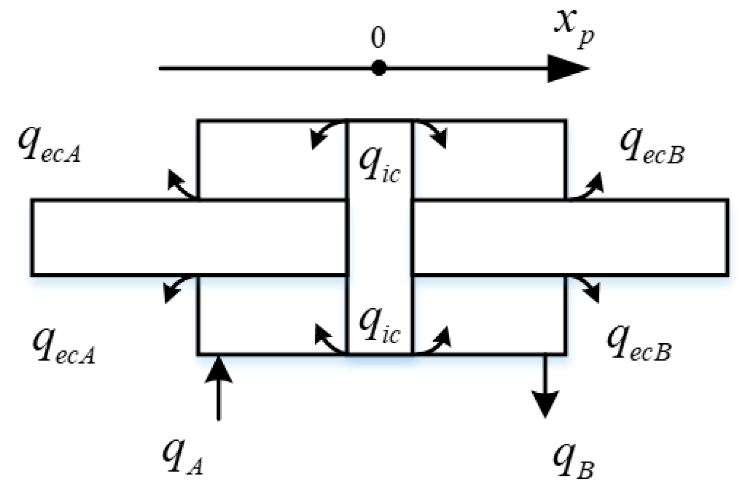
Considering load conditions, oil compression, internal and external leakage, and other factors, the flow distribution characteristics of the hydraulic cylinder are analyzed, as shown in Figure 4.
The flow continuity equation for cavities A and B of the hydraulic cylinder is:
q A = A p x ˙ p + C ic ( p A p B ) + C ec p A + V A β e p ˙ A q B = A p x ˙ p + C ic ( p A p B ) C ec p B V B β e p ˙ B
where C ic and C ec are the internal and external leakage coefficients of the hydraulic cylinder, V A and V B are the effective volumes of chambers A and B of the hydraulic cylinder and their pipelines, A p is the effective working area of the hydraulic cylinder, x p is the output displacement of the hydraulic cylinder, and β e is the effective bulk modulus of elasticity.
Furthermore, the flow continuity equation of the symmetric hydraulic cylinder can be expressed as:
Q p = A p x ˙ p + K ce P L + V t 4 β e P ˙ L
where C t is the total leakage coefficient of the hydraulic cylinder, where C t = C ic + C ec / 2 , and V t is the total compressed volume, where V t = V A + V B .
According to Newton’s second law, the load/force balance equation of hydraulic cylinders can be derived as follows:
A p ( p A p B ) = m t x ¨ p + B p x ˙ p + K x p + F L
where m t is the equivalent load mass, B p is the fluid viscosity damping coefficient, K is the load spring stiffness, and F L is the friction and external load interference force.

4. The Motor Direct Torque Control Algorithm

The included angle between the stator flux ψ s and rotor pole flux ψ f is defined as δ ; this angle is called the torque angle. The projection of the stator flux in the d-q coordinate system can be calculated as:
ψ d = ψ s cos δ ψ q = ψ s sin δ
According to Equations (1) and (14), the stator current equation in the d-q coordinate system is:
i d = ψ d ψ f L d = ψ s cos δ ψ f L d i q = ψ q L q = ψ s sin δ L q
We substitute Equation (15) into Equation (4) to obtain:
T e = 3 2 p n L d ψ s ψ f sin δ + 3 L d L q 4 ψ s 2 sin 2 δ
It can be seen from Equation (16) that electromagnetic torque consists of two parts: the first is electromagnetic torque, which is generated by the interaction between magnetic fields of the stator and rotor of the motor; the other part is reluctance torque, which is generated by the salient pole structure of the motor. For surface-mounted three-phase PMSM, the stator inductance satisfies L d = L q = L s , and Equation (16) can be expressed as:
T e = 3 2 p n L d ψ s ψ f sin δ
By analyzing the mathematical model of the stator shaft system, we can understand the basic idea of direct torque control. Assuming that the rotor flux and stator flux both have certain values, it can be seen from Formula (17) that δ directly affects the adjustment of motor torque. The change in the rotor flux always lags behind that in the stator flux, and torque regulation is a transient dynamic process, so it can be considered that the rotor flux remains unchanged in this process. Therefore, it is obvious that the amplitude of the stator flux remains unchanged during the control process, and the motor torque can be changed by adjusting δ . This is the essence of direct torque control. It can be seen that in order to control the motor, it is necessary to obtain its flux linkage equation, the vector form of which is:
ψ s = ( u s R s i s ) d t
where i s is the stator current vector, and u s is the stator voltage vector.
If the influence of stator resistance is ignored, Equation (18) can be simplified as:
ψ s = u s d t
It can be seen from Formula (19) that when the stator voltage vector inputs are different, the stator flux will be affected, and the direction of the voltage vector determines the direction of the stator flux increment. In this way, in the flux control of the motor, different voltage vectors can be used to cause the motor flux to reach the predetermined trajectory so as to achieve the effective control of the stator flux and torque.

5. Direct Torque Control of Servo Motor Based on Sliding-Mode Control

5.1. Space Vector Pulse-Width Modulation

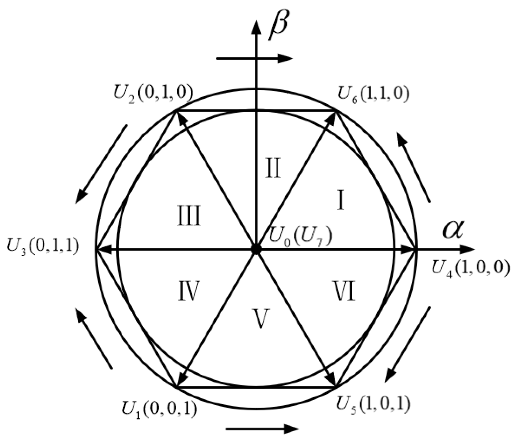
The SVPWM algorithm is actually a special combination of a switch trigger sequence and pulse width corresponding to a three-phase voltage inverter power device in an AC motor. This switch trigger sequence and combination generate a three-phase sine-wave current waveform with a 120° electrical angle difference and less distortion in the stator coil. A simplified diagram of voltage space vector is shown in Figure 5 below.
The instantaneous expression of three-phase symmetrical sinusoidal voltage is:
u a = U m cos ω t u b = U m cos ( ω t 2 3 π ) u c = U m cos ( ω t + 2 3 π )
Space vector synthesis results in:
U out = R e U out + J I m U out = 1.5 U m e j ( ω t π / 2 )
We determine the sector in which the voltage space vector U out is located, and we determine the basic voltage space vector used in this switching cycle.
U ref 1 = u β U ref 2 = 3 2 u α 1 2 u β U ref 3 = 3 2 u α 1 2 u β
The definitions of A, B, and C are as follows:
If U ref 1 > 0, then A = 1; otherwise, it is zero.
If U ref 2 > 0, then B = 1; otherwise, it is zero.
If U ref 3 > 0, then C = 1; otherwise, it is zero.
Let N = 4C + 2B + A, and find the sector position according to Table 1.
The vector action time can be calculated on the basis of the voltage space vector diagram as follows:
X = 3 T s u β U d c Y = 3 T s U dc ( 3 2 u α + 1 2 u β ) Z = 3 T s U dc ( 3 2 u α + 1 2 u β )
where T s is the switching cycle, U dc is the DC bus voltage, and X , Y , and Z are the basic vector action times.
The basic vector action time of each sector is presented in Table 2.
If T4 + T6 > Ts, overmodulation processing is required:
T 4 = T 4 T 4 + T 6 T s T 6 = T 6 T 4 + T 6 T s
The time point of sector switching is determined on the basis of sector N and the action time of the corresponding sector.
T a = ( T s T 4 T 6 ) / 4 T b = T a + T 4 / 2 T c = T b + T 6 / 2
The implementation of the SVPWM algorithm includes the sector determination of the reference voltage vector, the calculation of the non-zero and zero vector action times for each sector, and the determination of the switching point for each sector vector. Sector switching time is shown in Table 3. Finally, triangular carrier signals of a certain frequency are compared with the switching points of each sector vector so that the PWM pulse signals required by the converter can be generated.

5.2. Sliding-Mode Controller Design

On the basis of the modeling analysis of the servo motor in each coordinate system, it can be concluded that the mathematical model of the motor can be expressed as follows:
u s = R s i s + p n ψ s + j ω e ψ s ψ s = ψ f + L s i s
where ω e is the electrical angular velocity, u s is the stator voltage space vector, u s = u d + j u q , i s is the stator current space vector, i s = i d + j i q , ψ s is the stator flux space vector, and ψ s = ψ d + j ψ q .
At this time, the expression of electromagnetic torque T e is:
T e = 3 2 p n ( ψ d i q ψ q i d )
When the stator flux is in the same direction as axis d, ψ d = ψ s , and the stator flux amplitude can be expressed as:
ψ s = ( u d R s i d ) d t
In the second-order sliding-mode control algorithm, a dynamic system is defined as:
x ˙ = a ( x , t ) + b ( x , t ) u y = s ( x , t )
where x is the state variable, u is the input control quantity, y is the output function, and a , b are two smooth and uncertain bounded functions of the state quantity and time.
The control objective of Equation (29) is to cause the system to reach a sliding-mode surface s = 0 in a finite time and possess second-order sliding-mode dynamics:
d 2 y d t 2 = A ( x , t ) + B ( x , t ) d u d t
where A and B are undetermined functions.
Equation (30) is usually used for second-order sliding-mode control:
u = K a sgn ( k 1 y ˙ + k 2 y r sgn ( y ) ) + K b sgn ( k 3 y ˙ + k 4 sgn ( y ) )
where K a and K b are gain coefficients.
The super-spiral sliding-mode system in Equation (31) can be divided into two parts: one is a discontinuous sliding variable function, and the other is a continuous derivative.
The control law of the super-spiral sliding-mode control algorithm can be written as follows:
u = K p y r sgn ( y ) + u 1 u ˙ 1 = K i sgn ( y )
where K p is the proportional gain coefficient, and K i is the integral gain coefficient.
To obtain the expression of the flux controller, the sliding surface function of the flux is defined as:
s ψ = ψ s ψ s
where ψ s is the expected stator flux amplitude.
Second-order sliding-mode control based on the super-spiral algorithm can ensure that the state trajectory of the system can reach the sliding-mode surface in a short time, improve the robustness of the system, and simplify the calculation process. At this time, the expression of the flux controller is:
u d = K p s ψ r sgn ( s ψ ) + u sd u ˙ sd = K i sgn ( s ψ )
where K p and K i are parameters to be determined, and K p > 0 and K i > 0.
The sliding surface function defining the torque is:
s T = T e T e
where T e is the desired torque.
The same torque controller is designed as:
u q = K ps s ψ r sgn ( s T ) + u sq u ˙ sq = K is sgn ( s T )
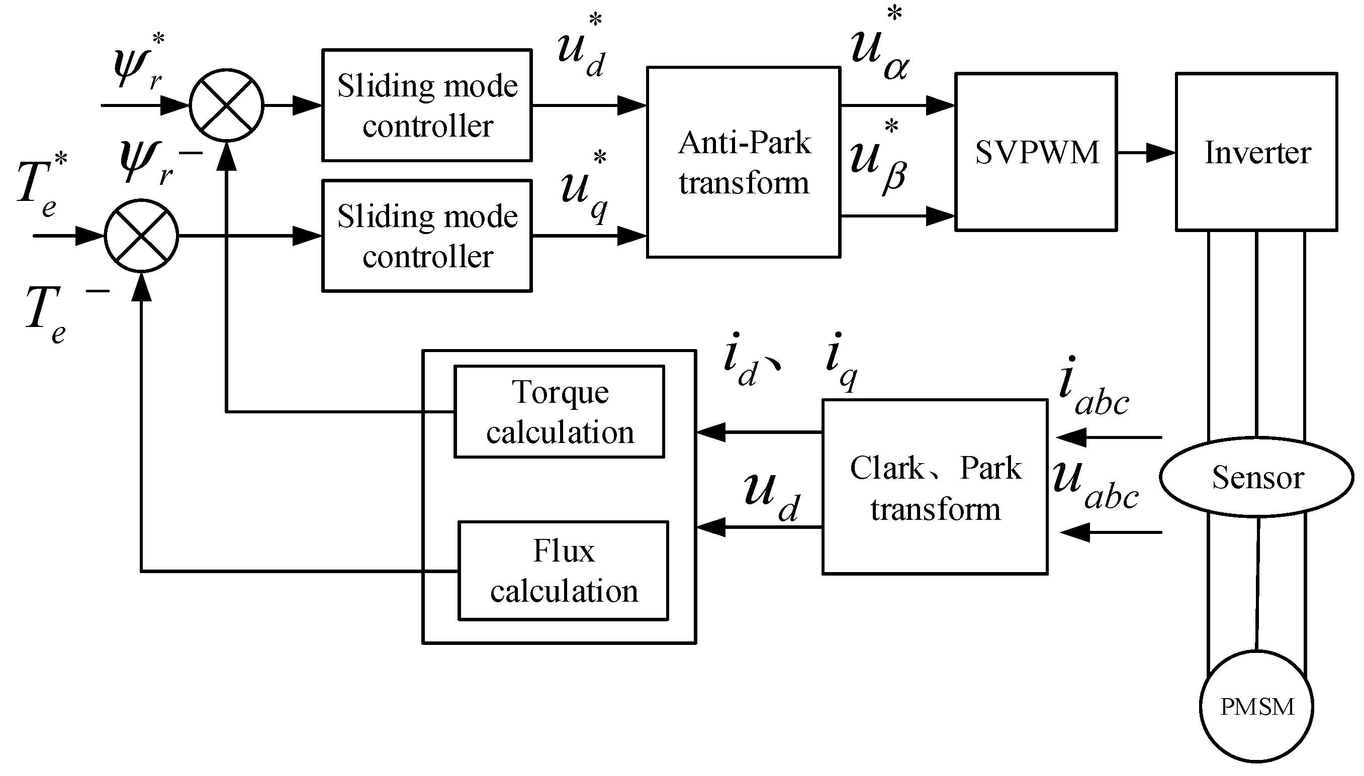
The principle of motor direct torque control based on sliding-mode control is shown in Figure 6. The system detects the current and the voltage value of the servo motor, calculates the actual value through the flux linkage and torque, compares the actual value with the expected target value, calculates the deviation, and controls the torque of the servo motor by outputting the control voltage of the servo motor through sliding-mode control so that the motor can reach the set torque value according to the control requirements.

6. Simulation Analysis

6.1. Building the Simulation Model

The traditional direct torque control simulation model is shown in Figure 7. On the basis of the voltage and current of the motor stator obtained via real-time detection, the amplitudes of the torque and flux are calculated and compared with the given values of torque and flux. The obtained pair of differences is used to control the amplitude of the stator flux and the angle between the vector and the flux. The torque and flux controllers directly output the required space voltage vector in order to achieve direct torque control. The control strategy is mainly composed of speed loop control, a Bang–Bang control module, a switch table selection module, flux linkage, and a torque calculation module.
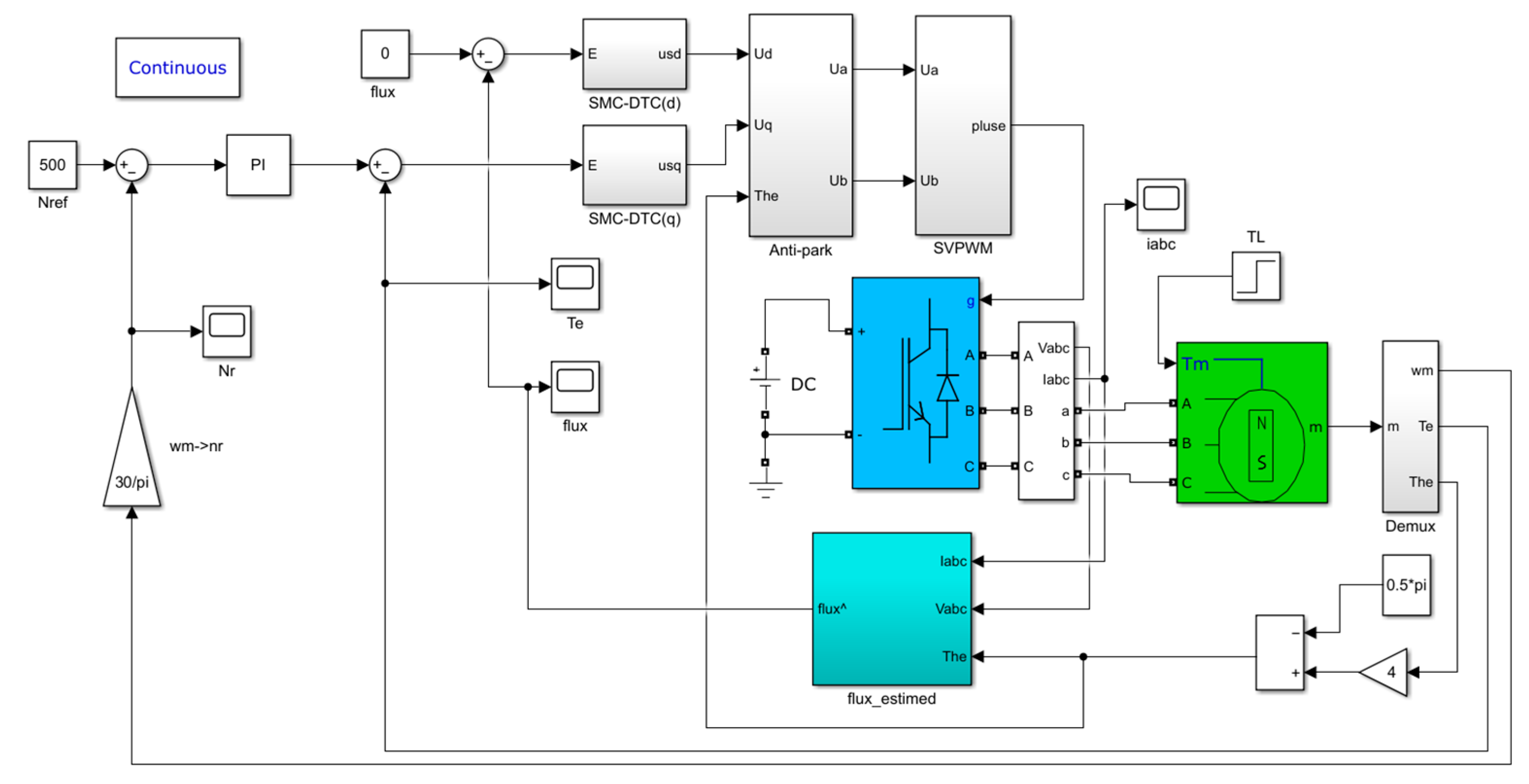
The optimized simulation model is shown in Figure 8. In accordance with the direct torque control principle of the servo motor based on sliding-mode control and the structural parameters of the servo motor, the simulation model of the servo motor was built with reference to the control schematic diagram. Its main components include a speed loop regulator module, a flux and torque regulator module, a flux and torque calculation module, an SVPWM module, etc. Based on the traditional DTC algorithm, space vector pulse modulation is added to improve the switching frequency of the inverter, and sliding-mode variable-structure control is used to replace the PID controller in order to reduce the torque ripple of the motor.
The SVPWM module is modeled on the basis of space vector pulse modulation, as described in Section 3 and shown in Figure 9.
The simulation modeling of the flux linkage and torque control module was carried out, as shown in Figure 10 and Figure 11.
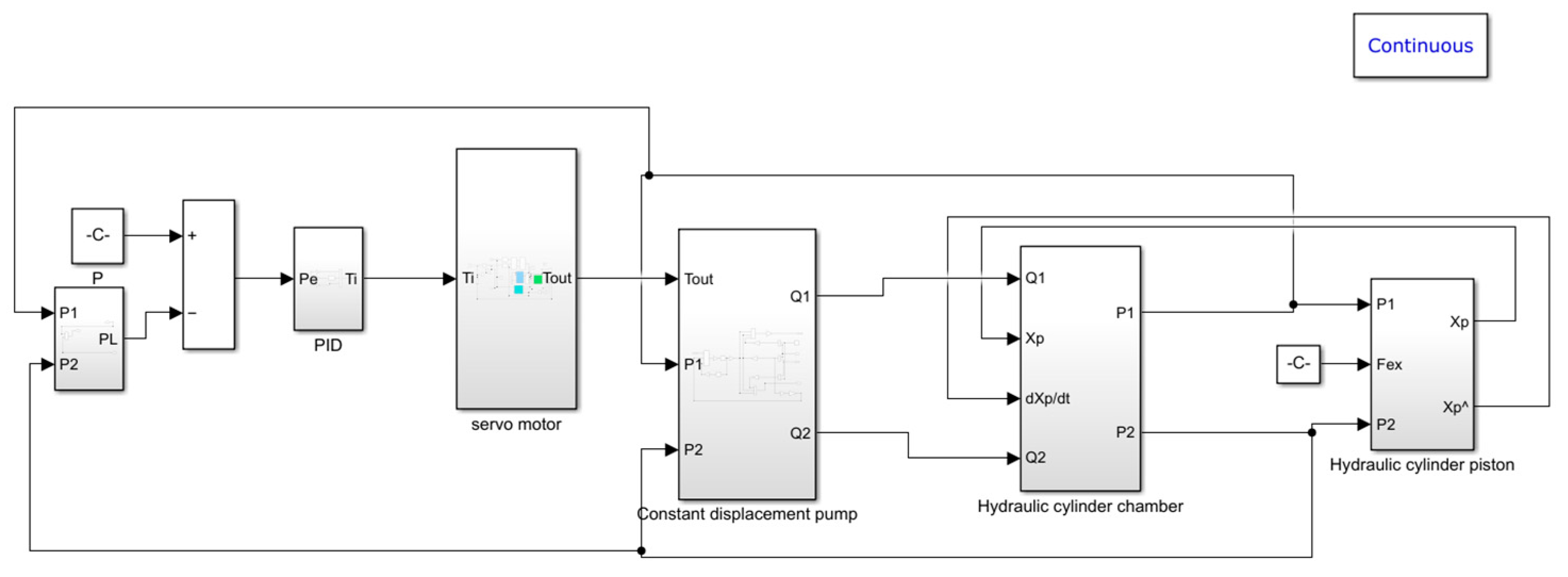
The hydraulic part was simulated and modeled using the flow continuity equation of the constant-displacement pump and the flow continuity equation of the hydraulic cylinder. By combining this with the servo motor simulation model, the overall simulation model of the DDVC electro-hydraulic servo system was obtained, as shown in Figure 12.
In the Simulink simulation process, model parameter setting is a very important aspect. Therefore, in order to simulate the actual working conditions of the pressure control of the electro-hydraulic servo pump control system as accurately as possible, it is necessary to configure the parameters of each simulation element in the system when building the overall simulation model of the system. Among these elements, hydraulic pump displacement, the hydraulic cylinder working volume, the piston effective area, and other parameters can be calculated on the basis of performance indicators; conversely, the leakage coefficient, the elastic modulus, and other parameters were determined on the basis of measurements or experience. The detailed system parameters are shown in Table 4.

6.2. Analysis of Simulation Results

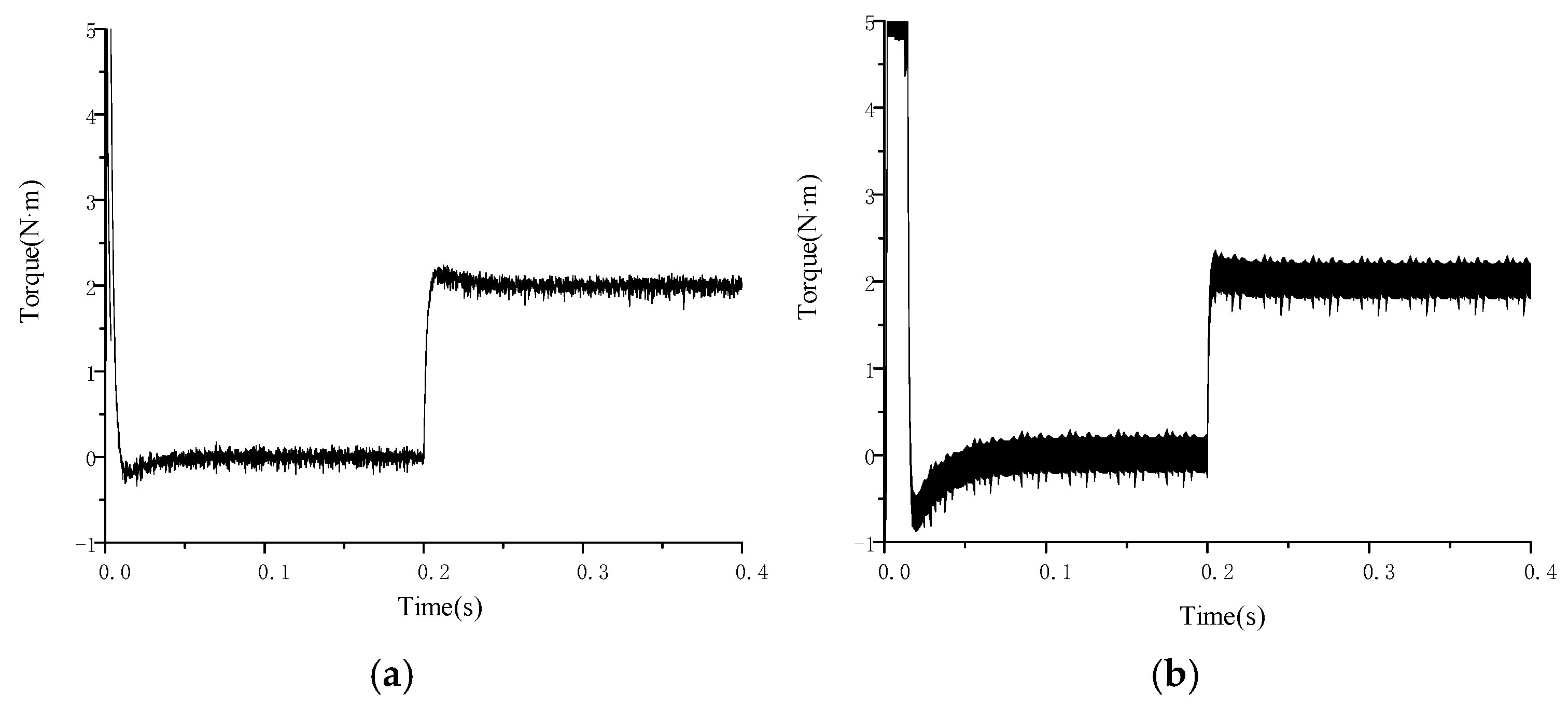
In the established traditional motor simulation model and the motor simulation model with the sliding-mode control method, the same conditions were set, and a load torque of 2 N·m was added at 0.2 s of simulation. The output speed and torque curves of the servo motor are shown in Figure 13 and Figure 14. It can be seen that for the two torque control methods, the speed has a good control effect and can be quickly adjusted to the required speed after adding the load. In traditional direct torque control, the speed overshoot of the motor is higher when it starts, and the adjustment time is slightly longer. The difference in the speed of the response to load disturbances between them is very small, but it can be seen from the torque curve that, compared with the traditional motor direct torque control method, the motor torque ripple is significantly reduced after adding the sliding-mode variable-structure control strategy.
In the DDVC electro-hydraulic servo simulation model, the step signal and sinusoidal signal are given in order to observe pressure control in the system. The pressure control effect is shown in the figure. As shown in Figure 15, given a 30-bar step response signal, the following process can be observed for the actual pressure and the expected pressure of the rodless cavity of the hydraulic cylinder.
It can be seen by comparing Figure 15 and Figure 16 that the dynamic response and steady-state response of the pressure curve of the DTC system based on sliding-mode control follow the expected pressure well, while the pressure control curve of the traditional variable-speed system shows an obvious overshoot and a relatively large steady-state error. By adding the sliding-mode control algorithm to the DTC system, the steady-state accuracy of the pressure is significantly improved.
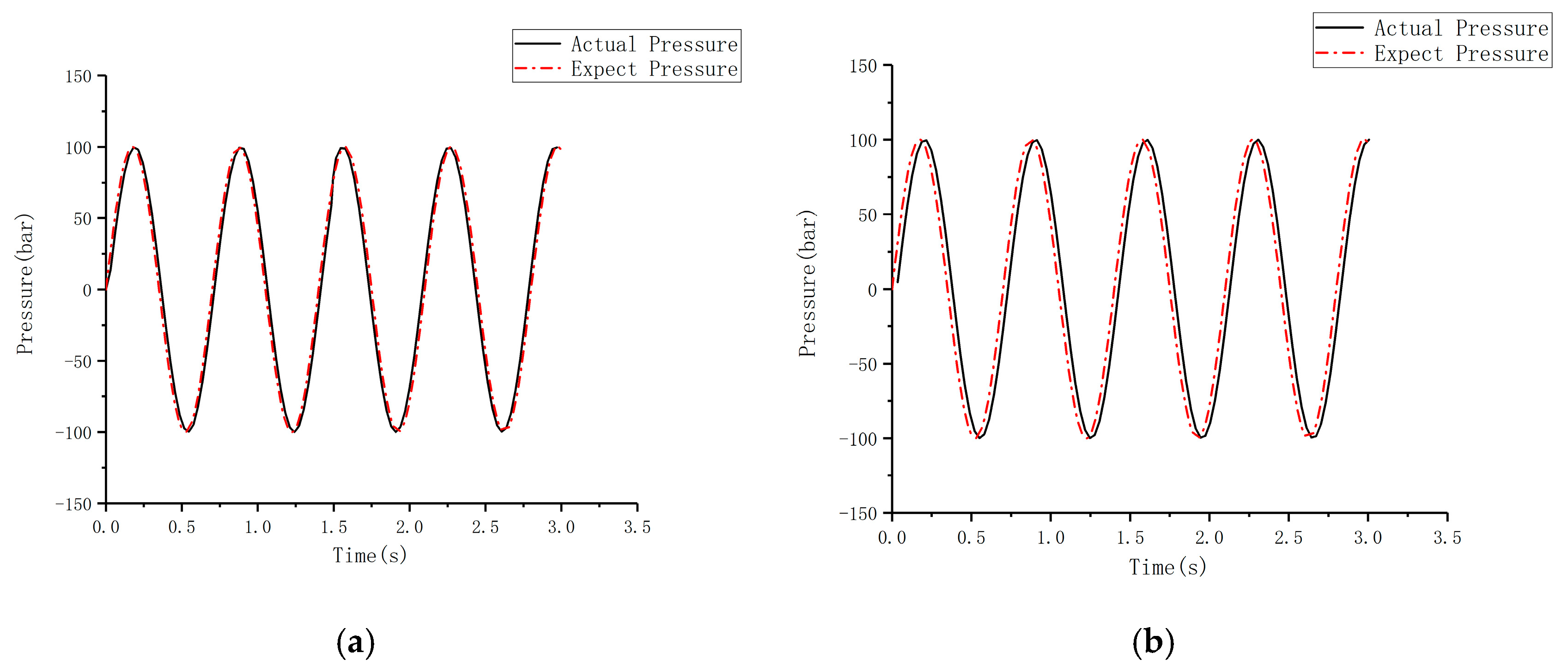
Given a sinusoidal signal with a system frequency of 2 Hz and an amplitude of 100 bar, the following process can be observed between the actual pressure and the expected pressure in the rodless cavity of the hydraulic cylinder, as shown in Figure 16.
It can be seen from the curve that under the load of the sinusoidal signal, the pressure control of the traditional variable-speed electro-hydraulic servo system exhibits obvious hysteresis. The DTC system based on a sliding-mode variable structure has better tracking characteristics and dynamic response characteristics to the expected pressure, and the control accuracy demonstrates significant improvement.

6.3. Experimental Content and Analysis

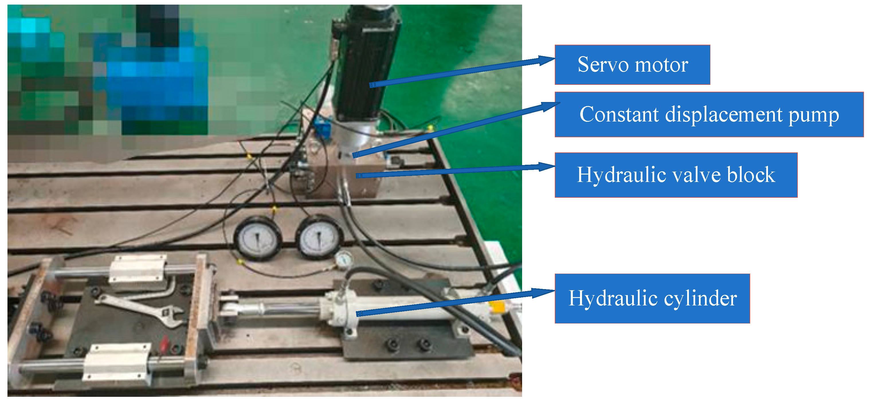
A DDCV electro-hydraulic servo pressure control test platform was built. The detailed values of parameters such as hydraulic pump displacement, hydraulic cylinder working volume, piston effective area, and other equipment are shown in Table 1. The pressure control strategy of DTC based on a variable structure for the synovium proposed in this paper was verified on the basis of experiments performed using the experimental platform. In accordance with the actual demands of the process and the hardware model of the system, the electrical schematic diagram and hydraulic valve block were designed, each element was installed and fixed in the electric control cabinet according to the electrical schematic diagram, and the cables were connected. All parts of the test bench after installation are shown in Figure 17. The main components of the experimental platform were an upper computer PLC, a Moog MSCII motion controller, a servo driver, a motor pump unit, a functional valve block, a working and loading hydraulic cylinder, an electric control cabinet console, etc.
The upper computer PLC sends the pressure control command to the Moog MSCII motion controller as an analog quantity. At the same time, the controller collects the pressure, displacement, temperature, and other information in the hydraulic system in real time through the sensor, calculates the torque signal required by the motor in combination with the pressure control algorithm program, and sends the output signal to the servo driver through the CAN bus communication mode to control the action of the motor pump unit. Finally, the target pressure difference in the hydraulic system is precisely controlled, thus constituting high-performance closed-loop pressure control. The main parameters of the test platform are shown in Table 5.
The specific implementation method of the experiment is as follows: First, the traditional variable-speed system control algorithm and the DTC control algorithm are built based on a sliding-mode variable structure in Simulink software, the program is downloaded to the Moog MACS axis control software, and the system logic control program is edited in the software. Then, the expected pressure signal in the experiment is set using the software. Two control methods—variable speed and DTC based on a sliding-mode variable structure—are adopted to control the system pressure. The pressure signal is collected by the pressure sensor in real time, and the pressure control results of the two methods are obtained through analysis and calculation. On the basis of a comparative analysis of the experimental results, the control accuracy and dynamic response effect of the DTC control algorithm based on a sliding-mode variable structure are verified with respect to system pressure.
The pressure control curves for the DTC system based on a sliding-mode variable structure when the given step signal changes from 10 bar to 20 bar and from 20 bar to 10 bar are shown in Figure 18a,b, respectively, while the pressure curves for the traditional variable-speed system are shown in c and d, respectively, in Figure 18. On the basis of placing the actual pressure curve and the expected pressure in the same interface, it can be concluded from the experimental curves that the overshoot and hysteresis of the pressure control of the traditional variable-speed system are serious, and the pressure accuracy error reaches about 3 bar. The DTC system based on a sliding-mode variable structure has a higher response accuracy of pressure control, and the overshoot demonstrates an obvious improvement. The dynamic response and steady-state response errors are much smaller than in the traditional DTC system. The pressure control accuracy is about 1 bar, and the accuracy is about 2 bar higher.
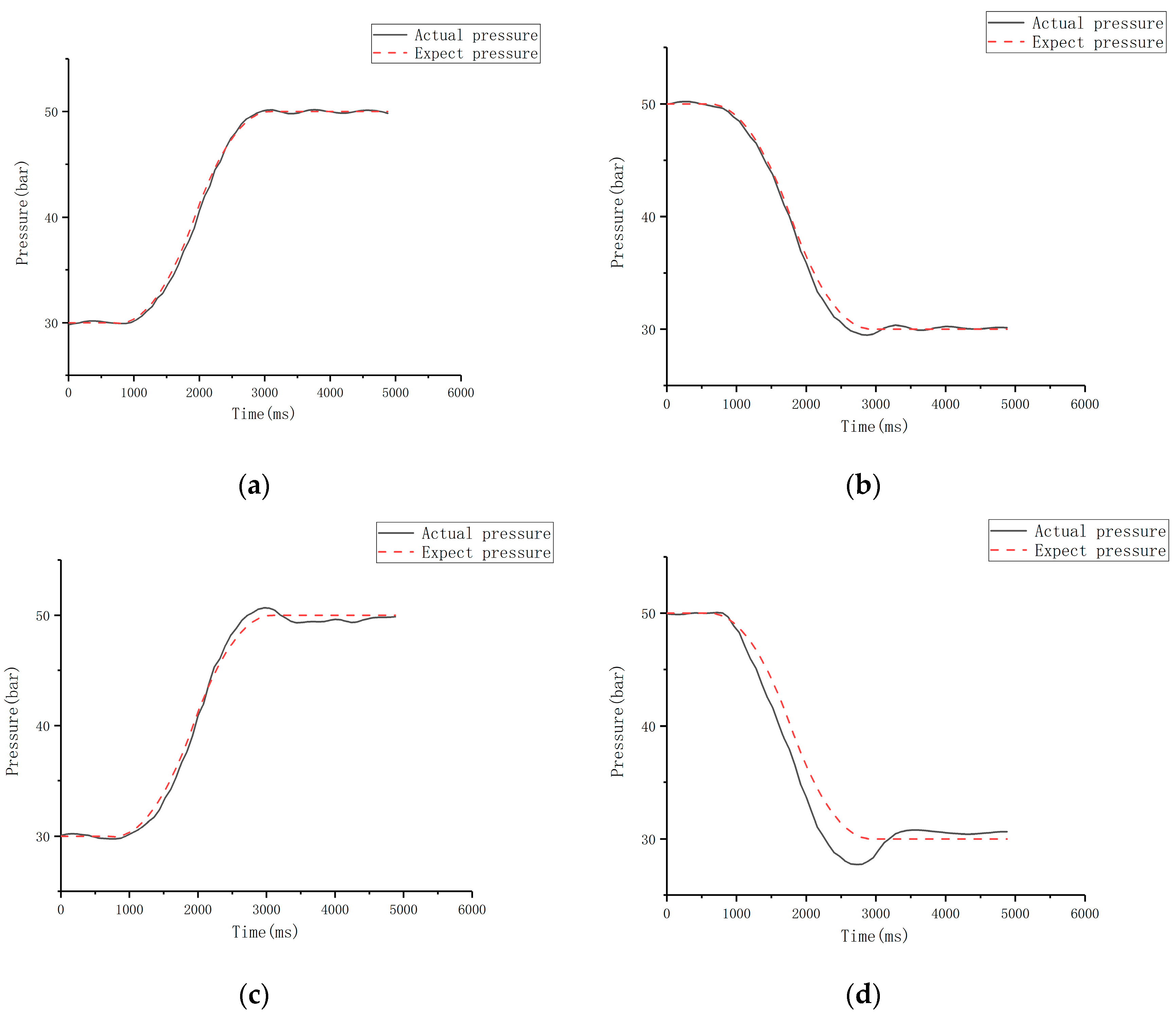
The pressure in the system when the given step signal changes from 30 bar to 50 bar and from 50 bar to 30 bar is shown in Figure 19. It can be seen from the experimental curve that the overshoot and hysteresis are obvious when performing pressure control using the traditional variable-speed system, and the steady-state error is large. The overshoot is about 3 bar, the steady-state error is about ±4 bar, and the maximum error can reach 5 bar. The pressure control response accuracy of the DTC system based on a sliding-mode variable structure is higher, the overshoot phenomenon is obviously improved, and the dynamic response and steady-state response errors are much smaller than in the traditional variable-speed system; the error is within ±2 bar, and accuracy is improved by about 2~3 bar, being better able to follow the expected pressure curve.
The pressure in the system when the given step signal changes from 10 bar to 50 bar and from 50 bar to 10 bar is shown in Figure 20. It can be seen from the experimental curve that the pressure control of the traditional variable-speed system still exhibits overshoot and hysteresis phenomena, and there is an obvious steady-state error, which is about ±4 bar. The pressure control response accuracy of the DTC system based on a sliding-mode variable structure is higher. The dynamic response and steady-state response errors are much smaller than in the traditional variable-speed system, the error is about ±1 bar, and the accuracy is improved by 2~3 bar, being better able to follow the expected pressure curve.

7. Conclusions

With the aim of solving the high-precision pressure control problem in DDVC electro-hydraulic servo systems, a direct torque control strategy for motors based on sliding-mode variable-structure control optimized using space vector pulse-width modulation technology was proposed, and the following conclusions were obtained:
(1) A mathematical model of the DDVC electro-hydraulic servo system was established, and the system pressure output function was derived.
(2) Aiming at the problem of high torque ripple in traditional DTC, a high-order sliding-mode control super-spiral algorithm was proposed to replace the original Bang–Bang controller, and space vector pulse-width modulation technology was added to keep the switching frequency of the inverter constant so as to solve the problem whereby accurate control is difficult to achieve at low speed.
(3) The simulation results show that, compared with traditional pressure control strategies in variable-speed systems, the DTC pressure control strategy based on sliding-mode variable-structure control proposed in this paper is able to effectively reduce the torque ripple of the motor, improve the dynamic response characteristics of the system, and further improve the precision of pressure control in the system. However, in the process of modeling the nonlinear aspects of the hydraulic system, some characteristics were idealized for the sake of convenience. Refining the nonlinear model of the hydraulic system would further improve the control accuracy.

Author Contributions

Conceptualization, Z.W. and G.Y.; formal analysis, G.Y. and C.J.; funding acquisition, G.C.; investigation, R.L.; methodology, R.L.; project administration, G.C.; resources, R.L.; software, P.J.; validation, G.Y.; writing—original draft, Z.W. and P.J.; writing—review and editing, Z.W. and T.Z. All authors have read and agreed to the published version of the manuscript.

Funding

This research was funded by the Key Project of the National Natural Science Foundation of China (No. 52275066), the Key Project of Science and Technology Research Project of Colleges and Universities of Hebei Province (No. ZD2021340), Key R&D projects of Hebei Province (No. 20314402D), and the Key Project of Natural Science Foundation of Xinjiang Uygur Autonomous Region (No. 2021D01A63).

Institutional Review Board Statement

Not applicable.

Informed Consent Statement

Not applicable.

Data Availability Statement

Not applicable.

Conflicts of Interest

The authors declare no conflict of interest.

References

  1. Yu, B.; Zhu, Q.; Yao, J.; Zhang, J.; Huang, Z.; Jin, Z.; Wang, X. Design, Mathematical Modelling and Force Control for Electro-Hydraulic Servo System with Pump-Valve Compound Drive. IEEE Access 2020, 8, 171988–172005. [Google Scholar]
  2. Zhao, P. Research on Position Control of Transferable Vane Electro-Hydraulic Servo Closed Pump Control System. Master’s Thesis, Yanshan University, Qinhuangdao, China, 2020. [Google Scholar]
  3. Yao, B. Study on Thermal Balance of Direct-Drive Volumetric Control Electro-Hydraulic Servo System. Master’s Thesis, Yanshan University, Qinhuangdao, China, 2020. [Google Scholar]
  4. Helbig, A. Injection moulding machine with electric-hydrostatic drives. In Proceedings of the 3rd International Fluid Power Conference (3. IFK), Aachen, Germany, 5–6 March 2002; pp. 67–82. [Google Scholar]
  5. Sedrak, D. Closed-loop electronic valuing and the application of variable voltage variable frequency in hydraulics. Elev. World 1999, 47, 66–72. [Google Scholar]
  6. Lee, S.R.; Hong, Y.S. A Dual EHA System for the Improvement of Position Control Performance via Active Load Compensation. Int. J. Precis. Eng. Manuf. 2017, 18, 937–944. [Google Scholar] [CrossRef]
  7. Ahn, K.K.; Nam, C.; Jin, M.L. Adaptive Backstepping Control of an Electro-Hydraulic Actuator. IEEE/ASME Trans. Mechatron. 2014, 19, 987–995. [Google Scholar] [CrossRef]
  8. Zhang, Z.; Li, H.; Qu, X.; Zhang, Z. Robust feedback linearization control of electro-hydraulic position servo system. Mach. Tool Hydraul. 2016, 44, 148–152. [Google Scholar]
  9. Han, J. Development and application of electro-hydraulic servo system. Mach. Tool Hydraul. 2012, 40, 15–18. [Google Scholar]
  10. Liu, D. Analysis and Compensation Method for Position and Force Control Characteristics of Electrohydrostatic System. Master’s Thesis, Yanshan University, Qinhuangdao, China, 2020. [Google Scholar]
  11. Ba, D.X.; Ahn, K.K.; Truong, D.Q.; Park, H.G. Integrated Model-based Backstepping Control for an Electro-Hydraulic System. Int. J. Precis. Eng. Manuf. 2016, 17, 565–577. [Google Scholar]
  12. Hoang, Q.D.; Lee, S.G.; Dugarjavn, B. Super-Twisting Observer-Based Integral Sliding Mode Control for Tracking the Rapid Acceleration of a Pison in a Hybrid Electro-Hydraulic and Pneumatic System. Asian J. Control. 2019, 21, 483–498. [Google Scholar]
  13. Luo, G.; Görges, D. Modeling and Adaptive Robust Force Control of a Pump-Controlled Electro-Hydraulic Actuator for an Active Suspension System. In Proceedings of the IEEE Conference on Control Technology and Applications (CCTA), Hong Kong, China, 19–21 August 2019; pp. 592–597. [Google Scholar]
  14. Helian, B.; Chen, Z.; Yao, B. Precision Motion Control of a Servo Motor-Pump Direct Drive Electro-hydraulic System with a Nonlinear Pump Flow Mapping. IEEE Trans. Ind. Electron. 2019, 67, 8638–8648. [Google Scholar]
  15. Zhang, Z.; Li, H.; Zhu, D. EHA feedback linearization optimal sliding mode surface double fuzzy sliding mode control. J. Beijing Univ. Aeronaut. Astronaut. 2016, 42, 1398–1405. [Google Scholar]
  16. Kou, F.; Du, J.; Wang, Z.; Li, D.; Xu, J. Nonlinear modeling and coordinate optimization of a semi-active energy regenerative suspension with an electro-hydraulic actuator. Algorithms 2018, 11, 12. [Google Scholar] [CrossRef] [Green Version]
  17. Zhao, S.; Gao, L.; Bin, Y. Multi-variable coupled mechanism and kinetic energy stiffness analysis method for a mechanical-electrical hydraulic system. Vib. Shock. 2018, 37, 27–33. [Google Scholar]
  18. He, D.; Wang, T.; Xie, J.; Ren, Z.; Liu, Y. An analysis on parametrically excited nonlinear vertical vibration of a roller system in corrugated rolling mills. Vib. Shock. 2019, 38, 164–171. [Google Scholar]
  19. Jiang, J.; Ge, Z.; Yang, C.; Liang, H. Differentiator-based discrete variable structure controller for direct drive electro-hydraulic servo system. J. Jilin Univ. 2018, 48, 1492–1499. [Google Scholar]
  20. Chen, G.; Jia, P.; Yan, G.; Liu, H.; Chen, W.; Jia, C.; Ai, C. Research on Feedback-Linearized Sliding Mode Control of Direct-Drive Volume Control Electro-Hydraulic Servo System. Processes 2021, 9, 1676. [Google Scholar] [CrossRef]
Figure 1. Hydraulic schematic diagram of the DDVC system: 1—servo motor; 2—constant-displacement pump; 3—temperature sensor; 4—pressure relay; 5—pressure-measuring connector; 6—check valve; 7—oil-replenishing accumulator; 8—high-pressure relief valve; 9—pressure sensor; 10—unloading valve; 11—symmetric hydraulic cylinder.
Processes 11 00092 g001
Figure 2. Schematic diagram of torque control pressure.
Processes 11 00092 g002
Figure 3. Hydraulic pump flow distribution.
Processes 11 00092 g003
Figure 4. Flow distribution of the hydraulic cylinder.
Processes 11 00092 g004
Figure 5. Voltage space vector diagram.
Processes 11 00092 g005
Figure 6. Block diagram of direct torque control based on sliding-mode control.
Processes 11 00092 g006
Figure 7. Traditional direct torque control simulation model.
Processes 11 00092 g007
Figure 8. Simulation model of direct torque control based on sliding-mode control.
Processes 11 00092 g008
Figure 9. Vector modulation simulation model.
Processes 11 00092 g009
Figure 10. Simulation model of the flux regulator.
Processes 11 00092 g010
Figure 11. Simulation model of the torque regulator.
Processes 11 00092 g011
Figure 12. Overall simulation model of the DDVC electro-hydraulic servo system.
Processes 11 00092 g012
Figure 13. Servo motor speed curve: (a) sliding-mode control DTC speed curve; (b) traditional DTC speed curve.
Processes 11 00092 g013
Figure 14. Servo motor torque curve: (a) sliding-mode control DTC torque curve; (b) traditional DTC motor torque curve.
Processes 11 00092 g014
Figure 15. Step signal pressure simulation curve. (a) Pressure curve of DTC system controlled by sliding-mode system under step signal. (b) Pressure curve of variable-speed system under step signal.
Processes 11 00092 g015
Figure 16. Sinusoidal signal pressure simulation curve. (a) Pressure curve of DTC system controlled by sliding-mode system under sinusoidal signal. (b) Pressure curve of variable-speed system under sinusoidal signal.
Processes 11 00092 g016
Figure 17. Electro-hydraulic servo pump control test platform.
Processes 11 00092 g017
Figure 18. Pressure change curves when step signal changes from 10 bar to 20 bar and 20 bar to 10 bar. (a) Step rise curve of DTC based on sliding-mode control; (b) step descent curve of DTC based on sliding-mode control; (c) step rise pressure change curve of variable-speed pressure control; (d) variable-speed pressure control step-down pressure change curve.
Processes 11 00092 g018
Figure 19. Pressure change curves when step signal changes from 30 bar to 50 bar and 50 bar to 30 bar. (a) Step rise curve of DTC based on sliding-mode control; (b) step descent curve of DTC based on sliding-mode control; (c) step rise pressure change curve of variable-speed pressure control; (d) variable-speed pressure control step-down pressure change curve.
Processes 11 00092 g019
Figure 20. Pressure change curves when step signal changes from 10 bar to 50 bar and 50 bar to 10 bar. (a) Step rise curve of DTC based on sliding-mode control; (b) step descent curve of DTC based on sliding-mode control; (c) step rise pressure change curve of variable-speed pressure control; (d) variable-speed pressure control step-down pressure change curve.
Processes 11 00092 g020
Table 1. Comparison between N and sector.
NSector
3I
1II
5III
4IV
6V
2VI
Table 2. Base vector action schedule.
NT4T6T0
1ZYT0 = (TST4T6)/2
2Y−X
3−ZX
4−XZ
5X−Y
6−Y−Z
Table 3. Switching schedule of each sector.
NTcm1Tcm2Tcm3
1TbTaTc
2TaTcTb
3TaTbTc
4TcTbTa
5TcTaTb
6TbTcTa
Table 4. System simulation parameter settings.
SymbolPhysical SignificanceSet Value
C ip [(m3/s)/Pa]Leakage coefficient of pump3 × 10−13
C ep [(m3/s)/Pa]External leakage coefficient of pump3 × 10−13
D p [L/r]Pump delivery0.008
C ic [(m3/s)/Pa]Leakage coefficient of hydraulic cylinder3 × 10−13
C ec [(m3/s)/Pa]External leakage coefficient of hydraulic cylinder3 × 10−13
k vic [N/(m/s)]Viscous damping coefficient150
F s [N]Maximum static friction25
F c [N]Coulomb friction15
V 0 [mL]One-side initial volume of hydraulic cylinder450
β e [N/m2]Oil elastic modulus6.5 × 10−8
A p [cm2]Effective area of piston71
J L [kg·m2]Moment of inertia on the axis of rotation2.65 × 10−4
B m Motor damping coefficient7.2 × 10−5
m t [kg]Converted load mass500
Table 5. Main parameters of the experimental platform.
SymbolPhysical SignificanceValue
C ip [(m3/s)/Pa]Leakage coefficient of pump1 × 10−13
C ep [(m3/s)/Pa]External leakage coefficient of pump1 × 10−13
D [mL/r]Pump delivery0.8
P P [kW]Pump rated power1
p m [Mpa]Maximum operating pressure of pump21
C ic [(m3/s)/Pa]Leakage coefficient of hydraulic cylinder1 × 10−13
K vp [N/(m/s)]Piston damping coefficient150
k Gas polytropic index1.3
F s [N]Sliding static friction25
F c [N]Sliding coulomb friction15
V 0 [mL]One-side initial volume of hydraulic cylinder450
β e [N/m2]Oil elastic modulus6.5 × 10−8
A [cm2]Effective area of piston71
m [Kg]Converted load mass2000
V gi [mL]Initial gas volume of accumulator200
P ai [Mpa]Initial pressure of accumulator3
V ai [mL]Initial oil volume of accumulator200
u [V]Rated voltage of servo motor220
P m [kW]Rated power of servo motor1
n [r/min]Rated speed of servo motor3000
J [kg m2]Servo motor moment of inertia2.65 × 10−4
Disclaimer/Publisher’s Note: The statements, opinions and data contained in all publications are solely those of the individual author(s) and contributor(s) and not of MDPI and/or the editor(s). MDPI and/or the editor(s) disclaim responsibility for any injury to people or property resulting from any ideas, methods, instructions or products referred to in the content.