Article

Manufacturing Cell Integrated Layout Method Based on RNS-FOA Algorithm in Smart Factory

Intelligent Manufacturing College, Panzhihua University, Panzhihua 617000, China
Processes 2022, 10(9), 1759; https://doi.org/10.3390/pr10091759
Submission received: 1 August 2022 / Revised: 27 August 2022 / Accepted: 30 August 2022 / Published: 2 September 2022

Abstract

:
The research on the layout of multi-layer manufacturing cells for smart factories is still in its infancy, but there is an urgent need to address this issue in building smart factories. This paper presents the Manufacturing Cell Integrated Layout (MCIL) Method, which integrates multiple layout forms of multi-layer and single-layer manufacturing cells. The paper develops a mathematical model of the MCIL problem which considers the multi-objective functions of logistics handling, occupied space, cell stability, lost time, and non-logistics relations, as well as the constraints between equipment in the cell and cells. An adaptive RNS-FOA algorithm is proposed to solve the high-dimensional and large-scale characteristics of the MCIL problem based on the research of academics. Lastly, a case demonstrates the outstanding contribution of the mathematical model to the solution of the MCIL problem, while simultaneously validating the efficiency and stability of the RNS-FOA algorithm for solving the MCIL problem.

1. Introduction

Cloud Manufacturing (CM), Cyber-physical Production Systems (CPS), and the Internet of Things (IoT) have been proposed successively in the exploration of manufacturing models for smart factories [1,2]. In order to cope with large fluctuations in commodity demand, smart factories must have rapid response capabilities. Early factories used information management systems for production management, but it was difficult to capture the real-time data situation of the factory [3]. With the development and application of IoT, the problem of capturing real-time data in factories has been solved, and the application of smart IoT in factories has subsequently been proposed [4]. Smart IoT in manufacturing can be defined as a future. In this future, physical objects, people, and systems (things) on the shop floor are connected through the IoT to build services critical to manufacturing [5]. Smart factories are a way to implement IoT, which is very consistent with IoT. The smart IoT system analyzes and evaluates key indicators of smart factories such as sustainable product life cycle management, equipment effectiveness, and workshop facility layout through industrial big data-driven decision-making [6].
The primary objective of appeal manufacturing models is to integrate advanced technology into the smart factory in order to realize technological advancements in the manufacturing mode [7]. As the manufacturing mode is optimized, the individualization of market demand becomes increasingly apparent. The Cellular Manufacturing System (CMS) for multi-variety and small-batch production meets the diverse manufacturing requirements of intelligent factories [8]. The intelligent logistics of the smart factory enable in-process products to precisely reach any location in the workshop, and the intelligent equipment enables unmanned operation [9]. The equipment layout and WIP handling throughout the smart factory break space limitations, so the cellular layout in the CMS is not limited to a single layout. Consequently, Yanlin et al. [10,11] proposed the Multi-layer Linear Manufacturing Cell Layout (MLMCL) and the Multi-layer U-shaped Manufacturing Cell Layout (MUMCL) and implemented them in enterprises. Concurrently, Mariem et al. [12] proposed and implemented a Multi-layer Equipment Layout in the Tunisian valve factory.
Currently, the multi-layer manufacturing cell layout proposed by scholars mainly focuses on the equipment layout of the intra-cell but does not consider the integrated layout of multiple inter-cells and intra-cells. The equipment layout problem of a smart factory is to consider the overall benefit, not just the intra-cell layout. In the overall equipment layout of the smart factory, both the intra-cell layout and the inter-cell layout affect the overall layout and affect each other. The application cases of smart factories require the integrated layout of manufacturing cells, and scholars lack research on this problem. Therefore, it is necessary to study the integrated layout of manufacturing cells.
The manufacturing cell integrated layout (MCIL) is better suited to the requirements of intelligent factories. Using a variety of manufacturing cell layout forms, including multi-layer manufacturing cells, single-layer manufacturing cells, U-shaped manufacturing cells, linear manufacturing cells, and circular manufacturing cells, MCIL conducts research on the smart factory’s overall layout. MCIL analyzes exhaustively internal and external logistics, equipment interference and production balance, etc., which are examples of high-dimensional and extensive combinatorial optimization problems.
The MCIL problem is different from the equipment layout within a single manufacturing cell, which involves a large quantity of equipment, high-dimensional objectives, and complex constraints. MCIL is, therefore, a large-scale, multi-objective, discontinuous, non-differentiable, and multi-constraint nonlinear combinatorial optimization problem. The MCIL problem cannot be solved in a single step and requires an iterative, layer-by-layer algorithm. The complexity of an MCIL problem is primarily reflected by three factors: mathematical modeling, multi-objective, and solution scale. The size of MCIL is (n × m). If the amount of equipment in the MCIL problem is m, the number of cells is n, and no other factors are considered. If you consider information such as cell constraints and I/O points, the MCIL problem will continue to grow. Considering NSGA III and FOA, this paper proposes an adaptive RNS-FOA (Reference-point Based Non-dominated Sorting, RNS, Fruit fly optimization algorithm, FOA) hybrid algorithm for designing adaptive parameters to solve the MCIL problem.
This paper presents a manufacturing cell integrated layout method, which integrates multiple layout forms of multi-layer and single-layer manufacturing cells to fill research gaps. The paper develops a mathematical model of the MCIL problem, and an adaptive RNS-FOA algorithm is proposed to solve the model. Lastly, a case demonstrates the outstanding contribution of the mathematical model to the solution of the MCIL problem while simultaneously validating the efficiency and stability of the RNS-FOA algorithm. The main contributions of this paper include the following:
(1)
Manufacturing cell integrated layout method for smart factory is proposed.
(2)
Based on the characteristics of smart factories, a multi-objective mathematical model of MCIL is constructed.
(3)
An adaptive RNS-FOA algorithm is designed, which is helpful for solving the combinatorial optimization problems of high-dimensional and large-scale.
(4)
High-quality cases can provide a reference for the cell layout of enterprise.
The rest of the article is organized as follows: Section 1 presents research pertaining to the contribution of the manufacturing cell layout problem. Section 2 presents the MCIL problem’s hypothesis and description, as well as its mathematical model. Section 3 designs the RNS-FOA algorithm. Section 4 presents case applications to demonstrate the efficacy of the MCIL and RNS-FOA algorithms. Finally, Section 5 presents the conclusions and outlook for the future.

2. Literature Review

In the 1950s, researchers began to investigate the layout of manufacturing cells, resulting in an abundance of research findings [13]. With time, the application of manufacturing cells has become increasingly complex, the layout forms have increased, and the scale of problem-solving has expanded, which has also increased the difficulty of academic research and application [14,15]. Consequently, research on the layout of manufacturing cells has been on the rise. The research content on manufacturing cell layout focuses primarily on the cell layout form and algorithm solution, so this article summarizes these two aspects.
The layout shape of the manufacturing cell has a direct impact on the factory’s layout and is an essential component of the CMS. CMS is primarily divided into manufacturing cell construction and layout. Building a manufacturing cell entails constructing the corresponding product or part family and equipment organization cell based on information about the production product or part and the degree of relationship between the equipment and the product or part. The layout of a manufacturing cell refers to the placement of equipment based on its fundamental characteristics, as determined by cell construction, product or part processing process path, quantity, and other factors. Forms of manufacturing cell layouts include single-row layout, double-row layout, U-shaped layout, annular layout, and others. The most prevalent cell layout types are linear, U-shaped, and circular. Yu et al. [16], Liu et al. [17], and Hamdia et al. [18], for instance, have studied the layout of linear manufacturing cells; He et al. [19], Qi et al. [20] and Frittandi et al. [21], U-shaped manufacturing cells; and Zheng et al. [22], circular robot cells.
There are few studies on the layout of multi-layer manufacturing cells, as the majority of research on the layout of manufacturing cells focuses on the layout of single-layer manufacturing cells. To meet the functions of multi-layer manufacturing cells, the application of multi-layer manufacturing cells in engineering applications is still in its infancy, as is academic research on multi-layer manufacturing cells. Yanlin et al. [10,11] proposed a form of equipment layout in a multi-layer U-shaped manufacturing cell. Mariem et al. [12] proposed the 3D facility layout problem, constructed a multi-layer linear facility layout problem within the workshop, and then implemented it in a Tunisian valve workshop.
In conclusion, as the global industry enters the era of Industry 4.0, researchers have shifted from single-layer to multi-layer layout research, and layout forms have become more diverse. However, most research focuses on the equipment layout in multi-layer manufacturing cells, and few investigate the integrated layout of multi-layer manufacturing cells and single-layer manufacturing cells with various layout forms.
The equipment layout problem in manufacturing cells has evolved from early single-objective research to current multi-objective research. There are numerous algorithms for optimizing multi-objective problems. In the past, accurate algorithms were the most prominent, whereas intelligent algorithms are the most prominent today. The multi-objective algorithm is separated into two categories by Professor Kalyanmoy et al. [23]. The first is to convert the multi-objective algorithm into a single-objective algorithm by employing a preference selection factor, and the second is to retain the attributes of the original objective function and implement a particular selection strategy for iteration. The first type of algorithm violates the original properties of the objective function, so the strategy selection of the preference selection factor has a direct impact on the solution, which also creates complications for the preference selection factor. The second category performs multi-objective goodness selection without violating the original objective function’s properties. In 1994, Kalyanmoy et al. [24] and Nidamarthi et al. [25] Srinivas proposed the first generation of the NSGA. On the premise of retaining multi-objective properties, the first generation of NSGA selects outstanding individuals for iteration via non-dominated sorting, thereby paving the way for future research on non-dominated sorting evolutionary algorithms. The NSGA algorithm’s search speed is slow. Professor Deb proposed a fast non-dominated sorting genetic algorithm (NSGA II) in 2000 as a solution to the problem of excessive computation [26]. Since its introduction, NSGA II has been favored by academics and engineers and has been widely adopted. It is not an exception when solving facility layout issues. It has also been widely implemented with positive outcomes [27]. In the application of multi-objective optimization, NSGA II performs well when solving problems with fewer than three objectives, but its performance degrades as the number of objectives increases. Professor Deb, therefore, proposed a non-dominated sorting genetic algorithm-based reference point in 2014 (NSGA III). Since its introduction, NSGA III has been widely adopted in engineering applications and academic research, with positive results. However, the algorithm for equipment layout remains NSGA II. Presently, NSGA III is utilized infrequently to solve multi-objective equipment layout problems. There is much-applied research on other problems (non-equipment layout problems) that have a greater impact, such as equipment inspection, workshop scheduling, logistics network design, and other fields. The MCIL problem has more than three objectives; the solution is more complex, and the problem’s scope is enormous. In order to obtain the stability, adaptability, and diversity of the algorithm solution, it is necessary to incorporate the NSGA III algorithm into the solution of the multi-layer manufacturing cell layout problem in order to address this issue.
The NSGA III algorithm has great advantages in the case of a large number of optimization targets, but it must be improved for the problem of the integrated layout of excessively large manufacturing cells. In 2012, Taiwanese scholar Pan Wenchao introduced the Fruit Fly Optimization Algorithm (FOA), which has simple and practical operations and is frequently used for parameter tuning of population diversity [28]. FOA is an optimal search that mimics how fruit flies, an insect, locate fruit food. First, individuals in a Drosophila population use their olfactory organs to search for food and send information regarding food odors to other Drosophila flies. When a fruit fly compares the food odor concentration of other fruit flies, it searches with its visual organs for the location with the highest food odor concentration and flies there. It then flies to the position with the highest concentration of food odor in the entire region, which is discovered through iterative evolution [29]. Standard FOA fruit flies conduct a local search with a fixed radius and a global assistance mechanism. When the position range (LR) of fruit flies is very large, it is simple for the standard FOA to converge on the local optimal solution; consequently, numerous researchers have developed enhancements. Adjusting and enhancing the local search radius, associating the number of iterations with the search radius, and developing an adaptive function are the responsibilities of Yuan et al. [30]. Meng et al. [31] modify the global assistance mechanism and the search radius weight coefficient. Wang et al. [32] proposed the simultaneous flight search of multiple groups of fruit flies in order to avoid achieving the optimal local solution. Currently, the majority of FOA research focuses on algorithm improvement for continuous problems, with less emphasis on discrete problems and equipment layout. This paper proposes a multi-objective, large-scale discrete problem for MCIL. The fixed local search radius and global assistance mechanism of FOA can easily result in the optimal local solution for this problem. Therefore, based on FOA and NSGA III, a combination of Reference-point Based Non-dominated Sorting (RNS) and FOA is proposed as an RNS-FOA hybrid algorithm, and adaptive population control is used to solve the MCIL problem.

3. Proposition

3.1. Problem Hypothesis

For academic research and engineering applications, it is necessary to make certain abstract assumptions about the MCIL situation.
(1)
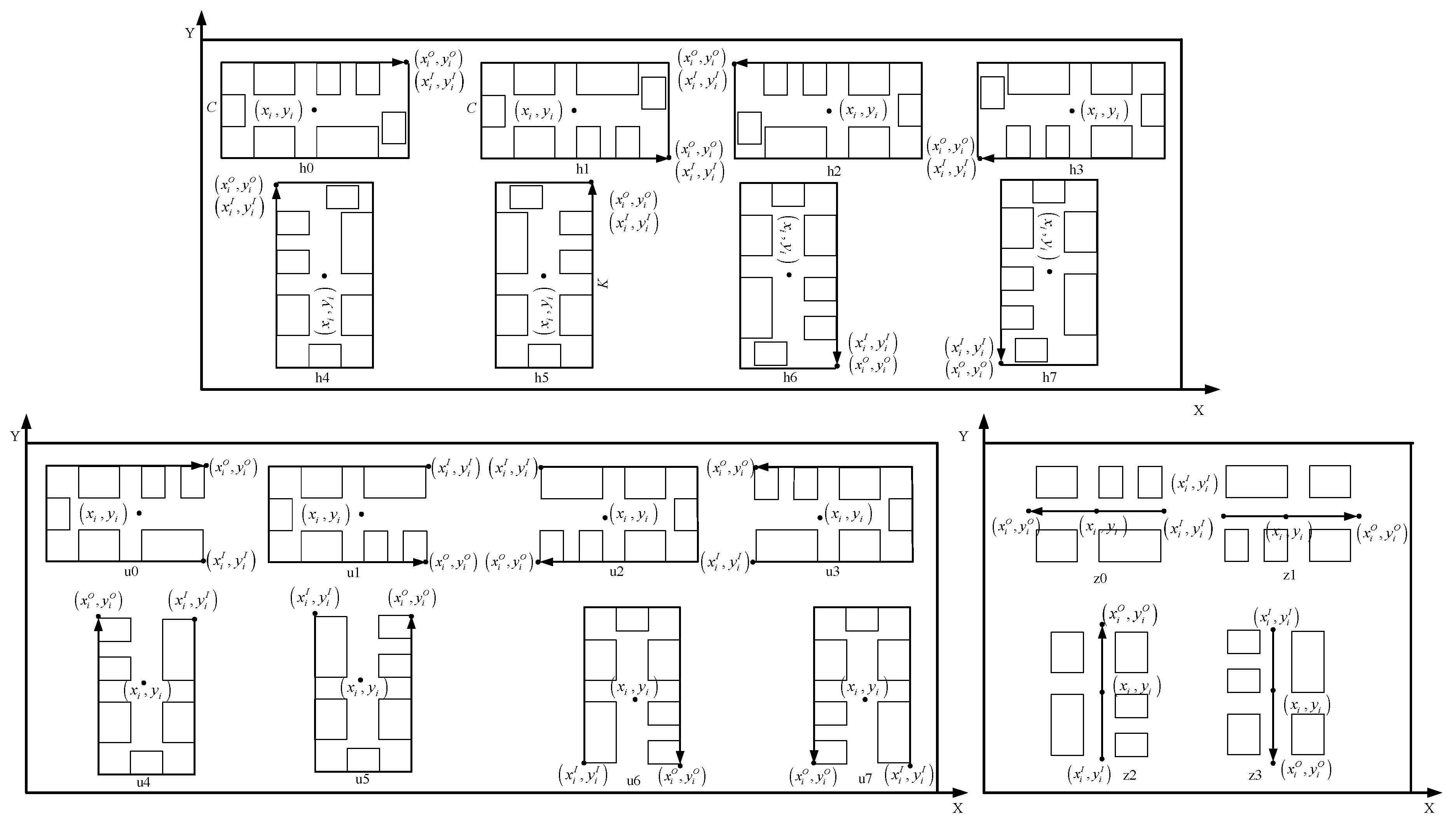
Shape of the equipment is a cuboid, and the manufacturing cell is a rectangular block.
Due to the prevalence of equipment with irregular shapes in engineering applications, with most of such equipment being cuboid, many scholars study the layout of equipment primarily in a cuboid form [33,34]. When equipment is not cuboid in shape, it is difficult to utilize some of the free space resources for other purposes. The device is abstracted into a cuboid, and the smallest cuboid that wraps around the device is used to represent it.
Three common layout forms are employed in MCIL: linear, U-shaped, and circular. The inter-cell layout in MCIL analyzes the problem for these three layout forms, all of which exist as blocks; therefore, rectangular blocks are used to represent the manufacturing cells.
(2)
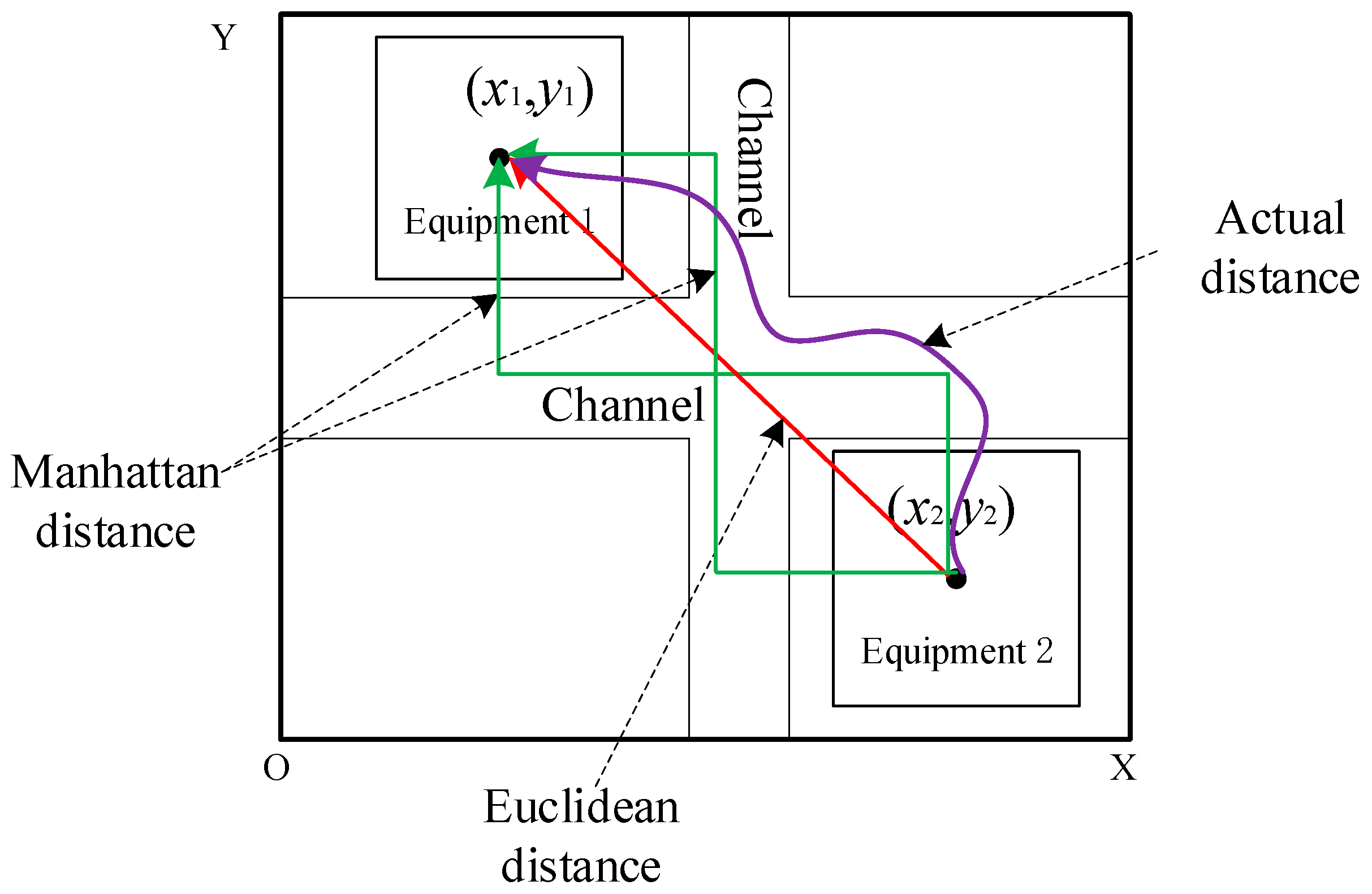
Handling distance is the Manhattan distance.
Distance is one of the most complicated aspects of a cell layout. In academic research, Euclidean distance, Manhattan distance, and Actual distance predominate. The actual distance is the distance that varies in real-time, and because the difference between factories is so great, it is seldom used. Practical distance study cell layout math problems [35], the Euclidean distance (Equation (1)) and the Manhattan distance (Equation (2)), have more research applications than the actual distance [36]. Manhattan distance, Euclidean distance, and Actual distance are shown in Figure 1.
Euclidean distance:
D = ( x i x j ) 2 + ( y i y j ) 2
Euclidean distance:
D = | x i x j | + | y i y j |
Cell layout problems require an Actual distance close to the production case. The Actual distance is a value that changes at any time according to the production situation, so the Manhattan distance and the Euclidean distance are used instead of the Actual distance. The Manhattan distance is closer to the Actual distance of a workshop with the channel in Figure 1. In a smart factory’s layout, the common workshops and equipment are primarily rectangular and cuboid, respectively. The conveyor belts and material handling passages in the factory are frequently aligned parallel to the workshop’s length and width. The end of the handling robot moves simultaneously using the Manhattan distance. The logistics handling distance is closer to the Manhattan distance since the path of the handling robot follows the material handling channel. The actual distance is closer to the Euclidean distance if the operator moves. The actual distance is closer to the Manhattan distance if the handling equipment (robot, AGV, bridge crane, etc.) moves. The intelligent/smart factory relies heavily on automation equipment. This paper uses the Manhattan distance to model the handling distance, which is more in line with the layout requirements for smart factories.
(3)
The same layer is transported on the same horizontal line, and the product is transported through the center point of the equipment.
The smart factory’s equipment has a high degree of automation, and the handling robot is more flexible. However, the handling robot’s purchase price is high, which is not conducive to cost control in the planning and construction of the smart factory. Therefore, a combination of conveyor belts and handling robots is utilized to design the factory’s material handling system. In this paper’s design of MCIL, the equipment on the same floor transfers products using a conveyor belt, so the logistics handling between the equipment on the same floor occurs along the same horizontal line.
In addition to the above assumptions, common assumptions such as the assumption that the cell can accommodate all equipment, the workshop can accommodate all cells, and the processing of products completed in the workshop are also required.

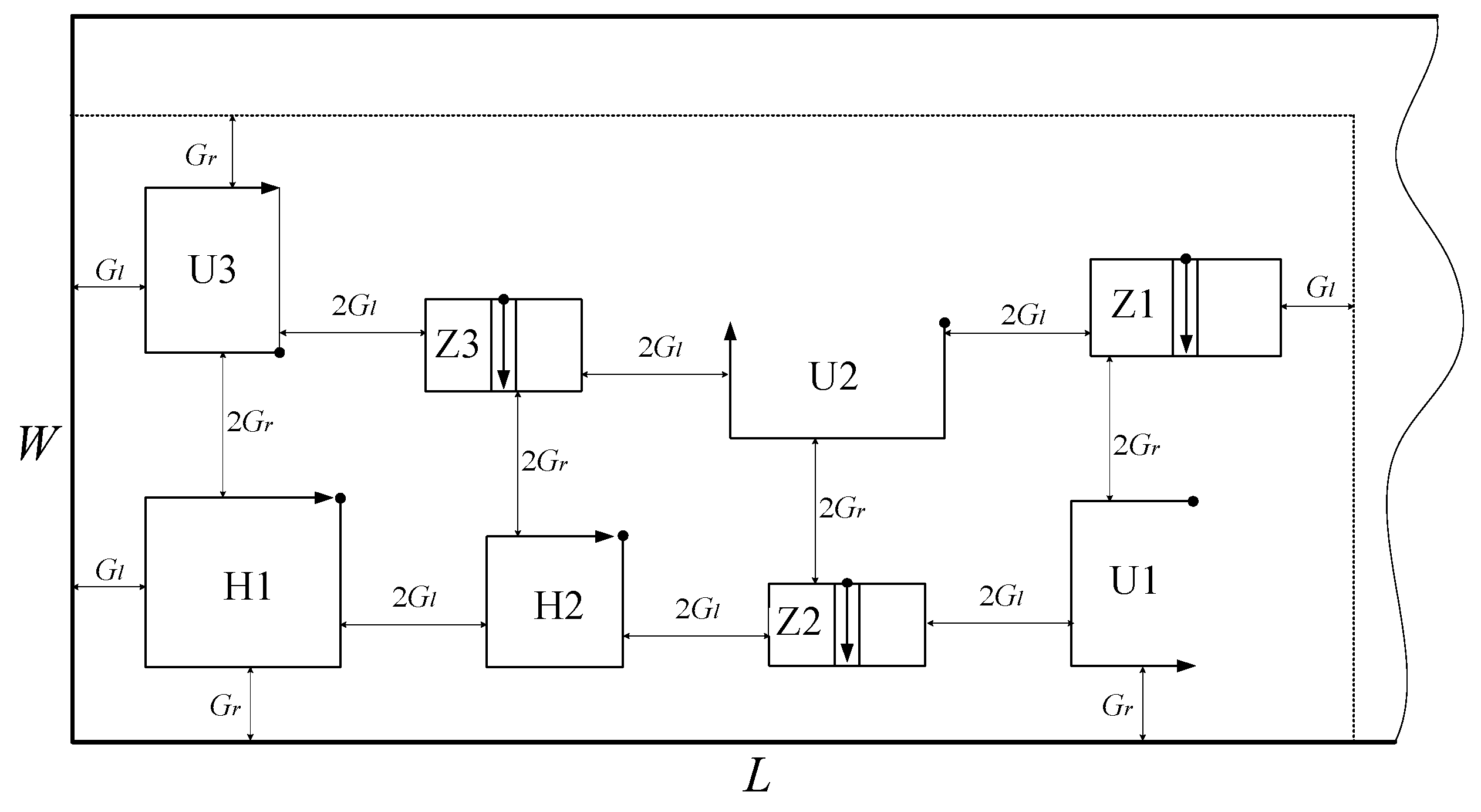
3.2. Problem Description

The traditional single manufacturing cell layout is a special case of equipment layout within a multi-layer manufacturing cell. Consequently, MCIL for smart factories includes a mixed layout of single-layer and multi-layer manufacturing cells, as well as three common layout forms: linear, U-shaped, and circular. Figure 2 depicts the building MCIL schematic design.
The layout in block form comprises the top views of all layout forms for the multi-layer manufacturing cell and the single-layer manufacturing cell. Assuming Gl is the minimum spacing limit in the X-axis direction and Gr is the minimum spacing limit in the width Y-axis direction, Figure 2’s three-dimensional integrated layout diagram can be abstracted to Figure 3’s plane layout diagram.
No. 1 is a single-layer U-shaped manufacturing cell; No. 5 is a single-layer linear manufacturing cell; No. 4 is a circular manufacturing cell; No. 2 and No. 6 are multi-layer linear manufacturing cell; No. 3 is a multi-layer U-shaped manufacturing cell. In the X-axis direction, the distance between the cells is 2Gl; the distance between the cell and the X-axis workshop wall is Gl; the Y-axis distance between the cell and the cell is 2Gr; the distance between the cell and the Y-axis workshop wall is Gr. In Figure 3, the green arrow depicts the primary flow direction of the cell.
MCIL is an integrated layout problem, so it is necessary to consider the comprehensive layout between cells and within cells. The layout within the manufacturing cell is shown in Figure 4.
The layout of Figure 4 is converted to a plane as shown in Figure 5, and the conversion method refers to Yanlin et al. [10,11].
The MCIL problem involves simultaneously solving the integrated layout problem within and between cells. The integrated layout is complicated. In the integrated layout problem, the outcome of the layout within the cell will influence the layout between cells. Similarly, the layout between cells will influence the layout within the cell. In order to achieve good results for the integrated layout, this paper considers the MCIL problem as a whole for optimization research and effectively resolves the connection between the cell layout and the layout within the cell.
The MCIL problem must also consider the layout scale expansion caused by the shape, orientation, entrances, and exits of the cell layout, in addition to the layout scale expansion caused by the total number of equipment layouts in the cell. For instance, a straight line has four layout directions: z0, z1, z2, and z3; a U-shape has eight layout directions: u0, u1, u2, u3, u4, u5, u6, and u7; a ring has h0, h1, h2, h3, and eight layout directions: h4, h5, h6, and h7. The MCIL problem is depicted in Figure 6.
Considering the integration of intra-cell device layout and inter-cell layout, the MCIL problem necessitates a comprehensive solution to the diverse cell layout directions caused by different cell shapes. Simultaneously, the MCIL problem must solve the equipment layout problem in the cell, which makes the scale of the solving problem very large, and it is very easy to fall into the optimal local solution, which complicates the problem.

3.3. Mathematical Modeling

MCIL takes the workshop layout as a whole; the number of equipment considered is the total number for the entire workshop, and the layout is designed as a whole. In the MCIL problem, the material handling volume consists of the intra-cell material handling volume and the inter-cell material handling volume; the total occupied space of the manufacturing workshop is proportional to the space occupied by each cell itself and the layout linkage between cells; loss of time, stability, and flexibility are all affected by the layout. Sexual and non-logistical relationships in the workshop must consider the proximity of products and equipment. The mathematical expression of the objective function of the MCIL problem is shown below.
(1)
Material handling
The material handling capacity of MCIL includes the sum of the handling between the equipment in the cell and the material handling capacity between the cells, so the objective function is more convenient and effective to construct by adding the two handling distances, as shown in Equation (3).
min D = k = 1 K q = 1 Q p = 1 P c e i l [ V p / B p ] ( | x k O x q I | + | y k O y q I | ) + i = 1 M j = 1 M p = 1 P c e i l [ V p / B p ] ( | x i x j | + | y i y j | + | z i z j | )
D is total logistics handling; i and j are equipment number; k and q are Manufacturing cell number; p is product category number; P is total number of categories; M is total number of equipment in the cell; V p and B p represent the total quantity of products to be processed in the cell and the quantity to be transported at one time; ( x k O , y k O ) is logistics input point; ( x q I , y q I ) is logistics output point; (xi, yi, zi) is coordinates of the center of the equipment; ceil[] means round up.
(2)
Workshop space occupation
The objective function of the MCIL occupied space is the multiplication of the length, width, and height of the layout, and the objective function is constructed as shown in Equation (4).
{ min V = L W H L = max { f k ( x k + K k 2 + G l ) + ( 1 f k ) ( x k + C k 2 + G l ) } W = max { f k ( y k + C k 2 + G r ) + ( 1 f k ) ( x k + K k 2 + G r ) } H = max { H k }
(3)
Lost time
The loss time of MCIL is the balance of processing products in the whole workshop process. It is necessary to consider the whole process, from the product entering the workshop to the finished product leaving the workshop, and the loss time of the whole process needs to be calculated. The relevant calculation formula is shown in Equation (5).
{ min T = c e i l [ V p / B p ] p = 1 P ( max ( T p i j ) length ( T p i j ) sum ( T p i j ) ) T p i j = [ ( t i p + δ ( d i j ) ) f i j p ]
(4)
Cell stability
The stability of MCIL needs to consider the stable value of all equipment in the workshop, and the stability of MCIL is shown in Equation (6).
min B = i = 1 M y i W i
(5)
Non-logistics relationship
The non-logistics relationship needs to consider the integration of the non-logistics relationship between the equipment in the cell and the non-logistics relationship between the cell and the cell. The mathematical model is constructed as shown in Equation (7).
{ min E = i = 1 M 1 j = i + 1 M 1 a i j b i j + k = 1 K 1 q = k + 1 K 1 a k q b k q d i j = | x i x j | + | y i y j | + | z i z j | d k q = | x k O x q I | + | y k O y q I |
Constraints for MCIL include non-overlapping elements, minimum spacing, and boundary constraints in addition to the built-in device internal constraints. Constraints are shown in Equations (8)–(11).
{ | x k x q | ( f c k K k + ( 1 f c k ) C k ) + ( f c k K q + ( 1 f c k ) C q ) 2 + 2 G l k , q | y k y q | ( f c k C k + ( 1 f c k ) K k ) + ( f c k C q + ( 1 f c k ) K q ) 2 + 2 G r k , q f k ( y k + C k 2 + G r ) + ( 1 f k ) ( x k + K k 2 + G r ) W L L W W H H
{ x i I = ( x i + C 2 ) z 0 + ( x i C 2 ) z 1 + x i z 2 + x i z 3 y i I = y i z 0 + y i z 1 + ( y i K 2 ) z 2 + ( y i + K 2 ) z 3 x i O = ( x i C 2 ) z 0 + ( x i + C 2 ) z 1 + x i z 2 + + x i z 3 y i O = y i z 0 + + y i z 1 + ( y i + K 2 ) z 2 + ( y i K 2 ) z 3 i = 1 z i = 1
{ x i I = ( x i + C 2 ) ( u 0 + u 1 ) + ( x i C 2 ) ( u 2 + u 3 ) + ( x i + K 2 ) ( u 4 + u 7 ) + ( x i K 2 ) ( u 5 + u 6 ) y i I = ( y i K 2 ) ( u 0 + u 3 ) + ( y i + K 2 ) ( u 1 + u 2 ) + ( y i + C 2 ) ( u 4 + u 5 ) + ( y i C 2 ) ( u 6 + u 7 ) x i O = ( x i + C 2 ) ( u 0 + u 1 ) + ( x i C 2 ) ( u 2 + u 3 ) + ( x i K 2 ) ( u 4 + u 7 ) + ( x i + K 2 ) ( u 5 + u 6 ) y i O = ( y i + K 2 ) ( u 0 + u 3 ) + ( y i K 2 ) ( u 1 + u 2 ) + ( y i + C 2 ) ( u 4 + u 5 ) + ( y i C 2 ) ( u 6 + u 7 ) i = 1 u i = 1
{ x i I = x i O = ( x i + C 2 ) ( h 0 + h 1 ) + ( x i C 2 ) ( h 2 + h 3 ) + ( x i K 2 ) ( h 4 + h 7 ) + ( x i + K 2 ) ( h 5 + h 6 ) y i I = y i O = ( x i + K 2 ) ( h 0 + h 2 ) + ( x i K 2 ) ( h 1 + h 3 ) + ( x i + C 2 ) ( h 4 + h 5 ) + ( x i C 2 ) ( h 6 + h 7 ) i = 1 h i = 1
Equation (8) indicates that any element k, q satisfies the condition, thereby constraining the lateral non-coincidence constraint of any adjacent elements. The workshop width W is used as a line wrapping constraint, and the cells are ordered along the width axis. L, W, and H are shop size constraints that represent shop-fixed values.
As depicted in Figure 6, the arrows denote the flow direction within the cell, the origin at the end of the arrow denotes the input point, and the end of the arrow denotes the output point. Different cell shapes result in distinct layout directions. The input point and output point of a cell are crucial logistics communication interfaces between cells, and their selection has a direct impact on logistics transfer. Input and output points are also dependent on the lengths, widths, and heights generated by the arrangement of the cell’s internal equipment and the arrangement order and direction selection between the cells. The relationship between the input point, the output point, the cell arrangement direction, and the cell center point is shown below, in which Equations (9)–(11) represent a straight line, a U shape, and a ring, respectively.

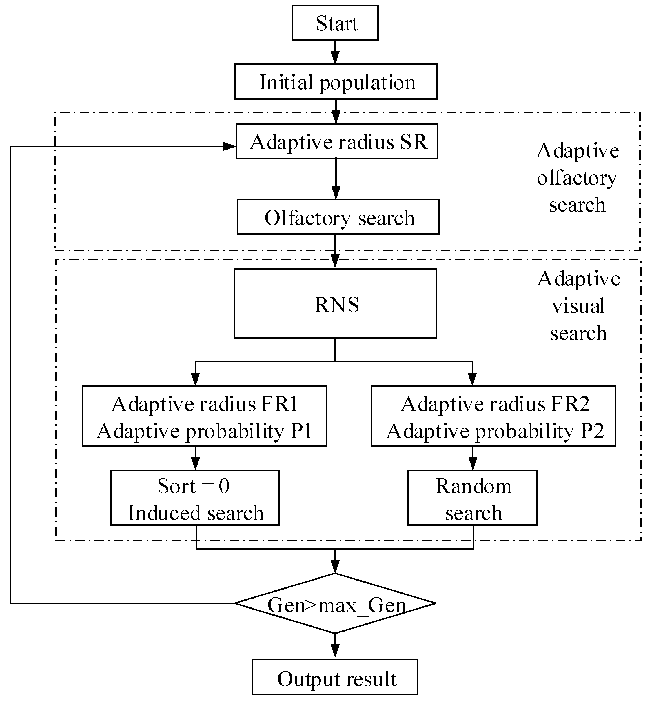
4. RNS-FOA Algorithm Design

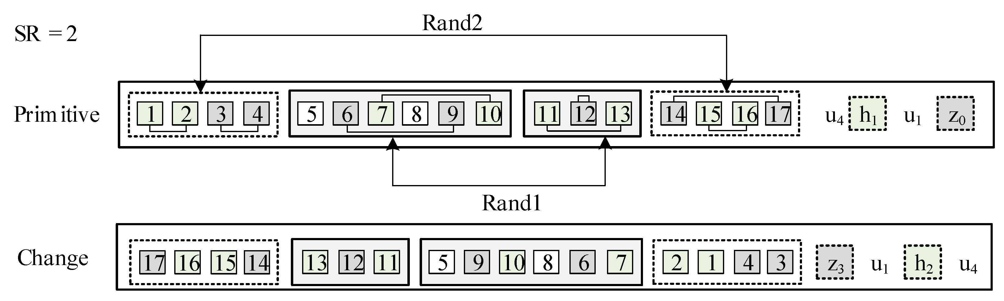
4.1. Coding and Initial Population

MCIL is encoded symbol order. The numbers represent the number of the device. The layout order and orientation of the cells are encoded using a two-segment method. The first-segment encoding indicates the arrangement order within the device and between the cells, whereas the rear-end encoding indicates the direction of cell arrangement. For example, the encoding is (1,2,3,4)(5,6,7,8,9,10)(11,12,13)(14,15,16,17)[u4,h1,u1,z0]. This example shows the layout of 4 cells of 17 devices, where [u4,h1,u1,z0] represents the layout order, layout form, and layout direction of the four cells. The layout forms of the four cells are U-shaped, annular, and linear in sequence. For example, (1,2,3,4) adopt the layout direction of u4, and the device layout order in the cell is the order of (1,2,3,4); (5,6,7,8,9,10) adopt the layout in the direction of h1, the layout order in the cell is (5, 6,7,8,9,10); (11,12,13) is arranged in the direction of u1, and the layout order in the cell is (11,12,13); (14,15,16,17) are arranged in the direction of z1, and the layout order in the cell is (14,15,16,17).
The initial population is randomly generated, such as random survival of P initial populations.

4.2. Adaptive Olfactory Search

The standard FOA is utilized primarily for the search of continuous problems, while the olfactory search is conducted within a radius of the Drosophila’s own position. This paper proposes an adaptive sense of smell based on its predecessors. The parameter of adaptive SR represents the number of exchanges, and SR is a dynamic value. Adaptive olfactory search is the exchange of individual loci to generate domain individuals. Assuming that when SR = 2, the chromosome randomly generates two pairs of loci for exchange and that the second segment of the cell orientation code will also change with the change in the previous cell position, it can be concluded that the chromosome generates two random pairs of loci for exchange when SR = 2. As depicted in Figure 7, if the newly generated individual is superior to the original, the new individual replaces the original and is added to the local Drosophila individual.

4.3. Adaptive Visual Search

The standard FOA is utilized primarily for the search of continuous problems, while the olfactory search is conducted.
The adaptive visual search incorporates a perturbed global assistance mechanism, wherein some fruit flies fly towards the optimal individual while others fly randomly, ensuring the diversity and stability of the global search.

4.3.1. Calculation of Food Concentration Value (Adaptation Value)

Most researchers continue to employ de-dimension weighted transformation to the single-objective optimization problem for the fruit fly optimization algorithm. Scholars such as Deb and Pratap have demonstrated that the optimization method of multi-objective weighted conversion to a single-objective problem will overlook a significant number of excellent individuals. Therefore, this paper introduces the RNS in NSGA III to the multi-objective fruit fly optimization algorithm. The RNS performs multi-objective sorting of food concentration values. After sorting, the highest-ranked fruit fly is selected as the current optimal fruit fly position.

4.3.2. Flight Strategy

For continuous problem optimization, the flight strategy flies a fixed distance to the optimal individual, whereas the standard FOA flight strategy cannot be used for discrete problems. Zheng [37] adopted the interpolation method to convert continuous FOA into a discrete shop-floor scheduling problem for discrete problem optimization. In order to ensure the diversity of the population and the stability of convergence, an adaptive dynamic flight strategy and the dynamic perturbation operation of certain Drosophila are proposed in this paper.
In the adaptive flight strategy, certain fruit flies choose between random or induced searches based on adaptive probability. The higher the RNS ranking, the greater the probability of induced search and the greater the probability of random search for flies with a lower ranking. Random search is to fly according to the adaptive search radius FR2, as depicted in Figure 8a. The original Drosophila continuous gene with the length of FR2 = 3 is selected at random, reordered randomly, and then inserted into the original Drosophila to produce a new Drosophila individual. The individual induction search of RNS sorting flies based on the adaptive radius FR1, as depicted in Figure 8b, randomly selects excellent Drosophila continuous genes with a length of FR1 = 2, replaces the genes in the same position as the original Drosophila, and obtains a new Drosophila individual.

4.4. General Process of RNS-FOA Algorithm
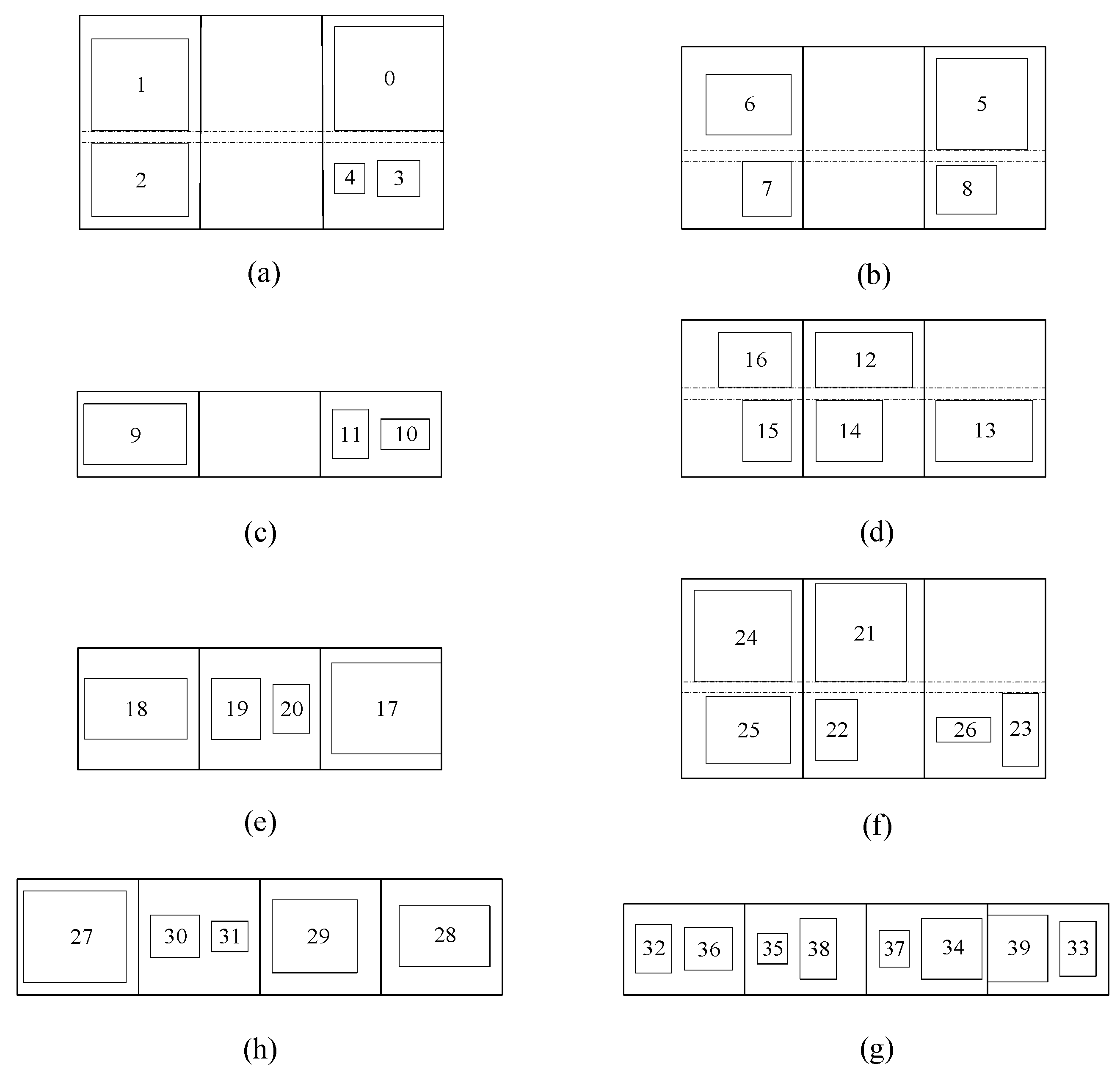
The overall process framework of the RNS-FOA algorithm is shown Figure 9.

5. Case

5.1. Case Data

This example uses 40 devices as the research object and has eight cells. The internal layout of the cell is three multi-layer linear, three multi-layer U-shaped, and two circular layouts. The equipment information is shown in Table 1.
The inter-cell product process path must pass through both the cell’s internal equipment and inter-cell logistics transportation. The primary steps of the product processing path occur within and between cells. Overall, the product’s processing path is lengthy and involves multiple cells. The information about processed products is shown in Table 2.
In addition to the logistics intensity relationship between equipment and equipment, there is also a non-logistics relationship. The importance of non-logistics relationships is represented by five levels of A, E, I, O, and U, as shown in Table 3.
In addition to the relevant information in the above table, there are W = 15, Gr = 1.5, and Gl = 1.5 constraints in order to ensure that the workshop can accommodate the equipment shown, so there is no limit to the workshop length L.

5.2. Case Solving Analysis

5.2.1. Parameters and Operating Environment

The operating environment is Windows 10 (64-bit, WA, US) operating system, configured as Intel i7-9750H 2.60 Ghz 12 cores, 24 Gb memory. The software adopts Anaconda3 (Python3.7, DE, US) and NumPy, math, Matplotlib, and other libraries. The population size of the RNS-FOA algorithm is 1000, and the maximum number of iterations is 30,000 generations, which are run ten times each.

5.2.2. Analysis of Running Results

The MCIL problem is simulated using adaptive RSN-FOA and NSGA III. The objective function includes logistics handling (D), occupied space (V), lost time (T), stability (B), and non-logistics relationship (E). The first three Pareto solution sets of the simulation results are selected, as shown in Table 4.
In Table 4, the RNS-FOA optimization outcomes are significantly superior to those of NSAG III. The RNS-FOA algorithm adjusts the population’s diversity adaptively and can produce better results for larger equipment scales. Figure 10 demonstrates the optimal Pareto solution set. However, when NSAG III solves the MCIL problem, it converges on a local optimal solution, resulting in a population with low diversity. Multiple levels of population diversity exist within the adaptive RNS-FOA, and it is easy to jump out of the optimal solution.
In Figure 11, the distance between the cell and the workshop wall is Gl = Gr = 1.5 m; the distance between the cell and the cell is 2 Gl, 2 Gr; the cell layout in the workshop with W = 15 m is a two-line layout; and the distance between the cell and the cell is 2 Gl, 2 Gr. The cell contains, as shown in Figure 12, two multi-layer linear layouts, two multi-layer U-shaped layouts, one single-layer linear layout, one single-layer U-shaped layout, and two single-layer annular layouts. This case demonstrates that there are various equipment layouts in MCIL, which can be multi-layer manufacturing cells or single-layer manufacturing cells, thereby enriching the workshop layout, and making it more flexible.

6. Conclusions

Throughout this work, we have taken a closer look at integrated layout methods for manufacturing cells. The layout method can provide application value for the facility layout design of smart factories, and the innovation of the solution algorithm can bring convenience to the solution of combinatorial optimization problems.
In this paper, the theory and application of MCIL problems involving single-layer fabrication cells, multi-layer fabrication cells, and linear, U-shaped, and annular shapes are demonstrated. The paper constructs the mathematical model of the MCIL problem in full accordance with engineering application requirements. The mathematical model considers the multi-objective functions of logistics handling, occupied space, cell stability, lost time, and non-logistics relationships, as well as the constraints and equipment selection within and between cells. The case demonstrates the significant contribution of the mathematical model to the solution of the MCIL problem, providing a benchmark for future studies of the same type. An adaptive RNS-FOA algorithm is proposed to solve the high-dimensional and large-scale characteristics of the MCIL problem based on the research of academics. The case contrasts the RNS-FOA algorithm with NSGA III, which is more effective at solving multi-objective problems, and demonstrates the effectiveness and stability of the RNS-FOA algorithm in solving the MCIL problem.
In future work, machine learning to solve the manufacturing cell layout problem is the trend because the method can be solved quickly. After machine learning is trained, the solution speed has great advantages, but the generalization ability of this method is poor. Therefore, using machine learning to solve combinatorial optimization problems is a direction that needs to be broken through.

Funding

This research was funded by the Sichuan Province Key Research Funds, grant number 22ZDYF3665.

Institutional Review Board Statement

Not applicable.

Informed Consent Statement

Not applicable.

Data Availability Statement

The data presented in this study are available in the article.

Conflicts of Interest

The author declares no conflict of interest.

References

  1. Xin, Y.; Guijiang, D. The Real-Time Prediction of Product Quality Based on the Equipment Parameters in a Smart Factory. Processes 2022, 10, 967. [Google Scholar] [CrossRef]
  2. Fátima, L.; Adriana, E.; Simon, C. Smart Pharmaceutical Manufacturing: Ensuring End-to-End Traceability and Data Integrity in Medicine Production. Big Data Res. 2021, 24, 100172. [Google Scholar] [CrossRef]
  3. Gyusun, H.; Jeongcheol, L.; Jinwoo, P. Developing Performance Measurement System for Internet of Things and smart Factory Environment. Int. J. Prod. Res. 2017, 55, 2590–2602. [Google Scholar] [CrossRef]
  4. Glenn, T. Sustainable Product Lifecycle Management, Industrial Big Data and Internet of Things Sensing Networks in Cyber-Physical System-based Smart Factories. J. Self-Gov. Manag. Economics. 2021, 9, 9–19. [Google Scholar]
  5. Navid, S.; Thomas, L.; Lars, L. Integration of digital factory with smart factory based on Internet of Things. Procedia CIRP 2016, 50, 512–517. [Google Scholar] [CrossRef]
  6. Seyed, M.S.S.; Yoo, H.S.; Sang, D.N. A Conceptual Definition and Future Directions of Urban Smart Factory for Sustainable Manufacturing. Sustainability 2022, 14, 1221. [Google Scholar] [CrossRef]
  7. Rao, B.C. Frugal Manufacturing in Smart Factories for Widespread Sustainable Development. R. Soc. Open Sci. 2021, 8, 210375. [Google Scholar] [CrossRef]
  8. Vikrant, S.; Gidwani, B.D. Cellular Manufacturing System Practices in Manufacturing Industries: A Pilot Study. Int. J. Indian Cult. Bus. Manag. 2022, 25, 550–569. [Google Scholar]
  9. Long, H.; Yiming, M.; Gaoxiang, W. IRobot-factory: An Intelligent Robot Factory Based on Cognitive Manufacturing and Edge Computing. Future Gener. Comput. Syst. 2019, 90, 569–577. [Google Scholar] [CrossRef]
  10. Yanlin, Z.; Jiansha, L.; Wenchao, Y. A New Cellular Manufacturing Layout: Multi-Floor Linear Cellular Manufacturing Layout. Int. J. Adv. Robot. Syst. 2020, 17, 1–14. [Google Scholar] [CrossRef]
  11. Yanlin, Z.; Jiansha, L.; Qing, Y. 3D-U Intelligent Manufacturing Cell Facilities Layout Based on Self-Adapting Multi-Objective Fruit Fly Optimization Algorithm. Comput. Integr. Manuf. Syst. 2020, 26, 2743–2752. [Google Scholar] [CrossRef]
  12. Mariem, B.; Marc, Z.; Roberta, C. 3D Facility Layout Problem. J. Intell. Manuf. 2021, 32, 1065–1090. [Google Scholar] [CrossRef]
  13. Shine-Der, L. Configuring Layout for a Cellular Manufacturing System. Int. J. Syst. Sci. 1998, 29, 557–564. [Google Scholar] [CrossRef]
  14. Chen, S.L.; Lee, K.M.; Li, I.C. Using MQTT IIot Gateway to Implement Bi-Direction Communication. J. Chin. Soc. Mech. 2020, 41, 585–594. [Google Scholar]
  15. Yan, W.; Siyu, X.; Huang, Z. Coupling Layout Optimization of Key Plant and Industrial Area. Processes 2020, 8, 185. [Google Scholar] [CrossRef]
  16. Yu, W.Y.; Fang, J.J. Integrated Cellular and Facility Layout Design with Linear Shaped Production Cell. Ind. Eng. Manag. 2016, 21, 102–108. [Google Scholar]
  17. Liu, J.; Liang, C.Y. Simulation Research and Implementation of Design-Oriented Hybrid Manufacturing Systems. Comput. Integr. Manuf. Syst. 2016, 22, 1264–1271. [Google Scholar] [CrossRef]
  18. Hamdia, M.; Islam, H.A.; Sayed, M.T. Heuristic-based Approach to Solve Layout Design and Workers’ Assignment Problem in the Cellular Manufacturing System. Int. J. Manag. Sci. Eng. Manag. 2022, 17, 49–65. [Google Scholar] [CrossRef]
  19. He, X.C.; Wu, X.; Ding, Y.K. Research of Manufacturing Cell Formation Based On U-Shaped Layout. J. Zhejiang Univ. Technol. 2017, 45, 88–93. [Google Scholar]
  20. Qi, B.S.; Qi, E.S. A Lean Design Method for U-Shaped Manufacturing Cell Facility Layout Based on Improved Genetic Algorithm. Ind. Eng. Manag. 2017, 22, 7–14. [Google Scholar]
  21. Frittandi, F.; Rainisa, M.H.; David, T.L. The Application of U-shaped Line Balancing at Furniture Manufacturing. Int. Conf. Ind. Syst. Eng. Technol. Innov. Manag. 2022, 2, 155–165. [Google Scholar] [CrossRef]
  22. Zheng, Y.Q.; Dai, D.M. Layout Design for Cellular Manufacturing Systems Based on Unidirectional Loop Flow Path. Comput. Integr. Manuf. Syst. 2013, 19, 1224–1231. [Google Scholar]
  23. Deb, K.; Jain, H. An Evolutionary Many-Objective Optimization Algorithm Using Reference-Point-Based Non-dominated Sorting Approach, Part I: Solving Problems with Box Constraints. IEEE Trans. Evol. Comput. 2014, 18, 577–601. [Google Scholar] [CrossRef]
  24. Reza, P.M.; Sadigh, R. Muiltiobjective Optimization Using Non-Dominated Sorting in Genetic Algorithms. J. Ind. Inf. Integr. 2017, 8, 49–58. [Google Scholar] [CrossRef]
  25. Nidamarthi, S.; Deb, K. An Integrated Simulation-Based Optimization Technique for Multi-Objective Dynamic Facility Layout Problem. Evol. Comput. 1994, 2, 221–248. [Google Scholar] [CrossRef]
  26. Deb, K.; Pratap, A. A Fast and Elitist Multiobjective Genetic Algorithm: NSGA-II. IEEE Trans. Evol. Comput. 2002, 6, 182–197. [Google Scholar] [CrossRef]
  27. Ahrari, A.; Blank, J.; Deb, K. A Proximity-Based Surrogate-Assisted Method for Simulation-Based Design Optimization of a Cylinder Head Water Jacket. Eng. Optim. 2020, 1, 1–19. [Google Scholar] [CrossRef]
  28. Nazir, H.; Bajwa, I.S.; Samiullah, M. Robust Secure Color Image Watermarking Using 4d Hyperchaotic System, Dwt, Hbd, and Svd Based on Improved FOA Algorithm. Secur. Commun. Netw. 2021, 28, 256–271. [Google Scholar] [CrossRef]
  29. Salehi, M.; Farhadi, S.; Moieni, A. A Hybrid Model Based on General Regression Neural Network and Fruit Fly Optimization Algorithm For Forecasting and Optimizing Paclitaxel Biosynthesis in Corylus Avellana Cell Culture. Plant. Methods 2021, 17, 1–13. [Google Scholar] [CrossRef]
  30. Yuan, X.; Cao, G.H.; Zhao, J. On A Novel Multi-Swarmfruit Fly Optimization Algorithm and Its Application. Appl. Math. Comput. 2014, 233, 260–271. [Google Scholar] [CrossRef]
  31. Meng, T.; Pan, Q.K. An Improved Fruit Fly Optimization Algorithm for Solving the Multidimensional Knapsack Problem. Appl. Soft Comput. 2017, 50, 79–93. [Google Scholar] [CrossRef]
  32. Wang, L.; Lv, C.X.; Zeng, Y.R. Literature Survey of Fruit Fly Optimization Algorithm. Control. Decis. 2017, 32, 1153–1162. [Google Scholar]
  33. Rahimi, V.; Arkat, J.; Farughi, H.R. A Vibration Damping Optimization Algorithm for the Integrated Problem of Cell Formation, Cellular Scheduling, and Intercellular Layout. Comput. Ind. Eng. 2020, 143, 6439–6456. [Google Scholar] [CrossRef]
  34. Forghani, K.; Ghomi, S.M.T. Joint Cell Formation, Cell Scheduling, and Group Layout Problem in Virtual and Classical Cellular Manufacturing Systems. Appl. Soft Comput. 2020, 97, 867–890. [Google Scholar] [CrossRef]
  35. Besbes, M.; Zolghadri, M.; Affonso, R.C. A Methodology for Solving Facility Layout Problem Considering Barriers: Genetic Algorithm Coupled With A* Search. J. Intell. Manuf. 2020, 31, 615–640. [Google Scholar] [CrossRef]
  36. Xie, Y.; Zhou, S.H.; Xiao, Y.Y. A Beta-Accurate Linearization Method of Euclidean Distance for The Facility Layout Problem with Heterogeneous Distance Metrics. Eur. J. Oper. Res. 2018, 365, 26–38. [Google Scholar] [CrossRef]
  37. Zheng, X.L.; Wang, L. An Order-Based Fruit Fly Optimization Algorithm for Stochastic Resource-constrained Project Scheduling. Control. Theory Appl. 2015, 4, 540–545. [Google Scholar]
Figure 1. Manhattan distance, Euclidean distance, and Actual distance.
Processes 10 01759 g001
Figure 2. Stereoscopic diagram of MCIL.
Processes 10 01759 g002
Figure 3. Plane diagram of MCIL.
Processes 10 01759 g003
Figure 4. Equipment layout within a single manufacturing cell. (a)—U-shaped manufacturing cell; (b)—linear manufacturing cell; (c)—circular manufacturing cell.
Processes 10 01759 g004
Figure 5. Plane diagram of single manufacturing cell. (a)—linear plane cell; (b)—U-shaped plane cell; (c)—circular plane cell.
Processes 10 01759 g005
Figure 6. Layout directions of different shapes.
Processes 10 01759 g006
Figure 7. Adaptive olfactory search.
Processes 10 01759 g007
Figure 8. Random and induced search strategy. (a)—LR2 = 3; (b)—LR1 = 2.
Processes 10 01759 g008
Figure 9. RNS-FOA flow char.
Processes 10 01759 g009
Figure 10. The population individual of the optimal solution set of the cell integration layout example.
Processes 10 01759 g010
Figure 11. Schematic diagram of the integrated layout between the cells.
Processes 10 01759 g011
Figure 12. Schematic diagram of the equipment layout in the integrated layout cell. (a)—Multi-layer Linear Manufacturing Cell; (b)—Multi-layer Linear Manufacturing Cell; (c)—Single-layer Manufacturing Cell; (d)—Multi-layer U-shaped manufacturing cell; (e)—Single-layer U-shaped manufacturing cell; (f)—Multi-layer U-shaped manufacturing cell; (g)—Single-layer Ring Manufacturing Cell; (h)—Single-layer Ring Manufacturing Cell.
Processes 10 01759 g012
Table 1. Device information.
No.[li,wi,hi]WeightTimeCell Shape
0[1.8,1.5,1.7]20030Z1
1[1.6,1.2,1.5]15015
2[1.6,1.4,1.2]16018
3[0.7,0.5,0.6]8021
4[0.5,0.5,0.5]5020
5[1.5,1.2,1.5]13025Z2
6[1.4,1.0,1.0]12018
7[0.8,0.8,0.9]9010
8[1.0,0.5,0.8]10016
9[1.7,1.5,1.0]18014Z3
10[0.8,0.7,0.5]9013
11[0.6,0.5,0.8]7012
12[1.5,1.6,0.9]18011U1
13[1.6,1.5,1.0]19018
14[1.0,1.1,1.0]11027
15[0.8,0.9,1.0]10028
16[1.2,0.8,0.9]11024
17[1.8,1.6,1.5]21025U2
18[1.7,1.8,1.0]18042
19[0.8,0.8,1.0]11045
20[0.5,0.6,0.8]7031
21[1.7,1.5,1.6]18038U3
22[0.8,0.7,1.0]13041
23[0.6,0.8,1.2]8036
24[1.6,1.4,1.5]16012
25[1.4,1.2,1.1]14042
26[0.9,1.0,0.4]13037
27[1.7,1.4,1.5]18022H1
28[1.6,1.5,1.0]16042
29[1.4,1.6,1.2]12024
30[0.9,0.8,0.7]10039
31[0.4,0.6,0.5]5025
32[0.6,0.5,0.8]6028H2
33[0.7,0.6,0.9]7026
34[1.0,1.1,1.0]12021
35[0.5,0.5,0.5]6016
36[0.8,0.4,0.7]8014
37[0.5,0.5,0.6]7019
38[0.7,0.6,1.0]9020
39[0.9,1.0,1.1]11025
Table 2. Product information.
No.Product Process PathProcessing BatchHandling Batches
116-12-15-14--7-8-6-5--21-25-22-26-24-23--32-36-37-34-33-39600010
210-9-11--0-4-2-3-1--19-18-17-20500010
320-19--3-2-1-0--9-11--26-22-25-23--33-32-34-38-36-35800010
44-0-1--26-22-25-23--32-36-37-34-33-39600020
528-31-30-27-29--24-23-25-26--15-13-16--1-4-0300010
67-8--14-16--31-28-27--37-36-33-32--6-7-5500020
714-16--1-4-0--10-9--18-17-20400010
829-27-29-31--22-25-24-21--35-34-37-38-35700010
96-5-8--39-35-36-33-38-37--16-12-15-14500020
1038-36-32--15-13-16--24-23-25-26400010
Table 3. Non-logistics hierarchy.
O-DGradeO-DGradeO-DGradeO-DGrade
0-1O14-16I27-31I36-39A
0-2I17-18A28-29O38-39I
0-4I17-19I28-30EL1-L3O
1-3A18-19I28-31AL1-U2E
3-4E18-20E30-31OL1-U3O
5-7E21-23A32-34OL1-H2I
6-7I21-24I32-36EL2-U2I
6-8A21-26I32-37OL2-H1E
9-10I22-24A32-39IL2-U1I
9-11E22-25E33-36IL2-U2I
10-11O23-25O33-38EL2-H1A
12-13E23-26E34-35IU1-H1O
12-14E24-25I34-36IU2-H2A
12-16O24-26O34-38AH1-H2I
13-15A27-29I35-38O
Table 4. Integrated layout example solution results.
AlgorithmMCIY Layout SchemeD, V, T, B, E
RNS-FOA(27,30,31,29,28)(25,22,26,23,24,21)(36,32,35,38,37,34,33,39)(9,11,10)(7,8,6,5)(18,19,20,17)(15,14,13,16,12)(2,4,3,1,0)[h0,u0,h5,z3,z3,u4,u1,z3]187595.0,912.0,1588942.6,4642.6,30.4
(25,22,23,26,24,21)(32,36,33,39,34,37,35,38)(14,13,15,16,12)(17,20,19,18)(6,8,5,7)(2,3,4,1,0)(27,28,31,30,29)(9,10,11)[u4,h1,u1,u0,z2,z3 h5,z1]189310.0,835.8,1577643.2,4674.1,31.2
(31,30,28,27,29)(8,7,5,6)(19,20,18,17)(11,10,9)(36,35,32,34,37,38,33,39)(13,14,15,12,16)(25,26,23,22,24,21)(4,3,2,0,1)[h0,z0,u3,z2,h5,u1,u4,z2]198000.0,855.2,1512590.8,4642.6,30.7
NSAG III(33,39,35,37,38,36,32,34)(7,8,5,6)(19,20,17,18)(13,14,16,12,15)(22,25,24,26,21,23)(1,0,3,4,2)(9,11,10)(28,29,31,30,27)[h4,z3,u6,u5,u7,z2,z1,h0]210657.5,1020.3,1812176.8,5482.8,33.2
(38,39,37,34,35,33,36,32)(28,30,31,27,29)(19,20,17,18)(16,14,13,15,12)(25,24,26,23,22,21)(3,2,1,0,4),(8,7,6,5)(11,10,9)[h5,h5,u4,u0,u4,z3,z1,z3]199355.0,1024.1,2043603.8,5107.80,33.2
(12,15,14,16,13)(5,8,6,7)(22,24,21,26,25,23)(11,10,9)(17,18,20,19)(36,32,33,39,34,35,37,38)(27,29,28,31,30)(1,4,3,0,2)[u7,z0,u6,z2,u4,h3,h3,z2]198525.0,986.4,2140589.5,5304.9,34.4
Publisher’s Note: MDPI stays neutral with regard to jurisdictional claims in published maps and institutional affiliations.

