Abstract
The high intensity of solar radiation and long sunshine time in the Turpan area lead to the necessity of sunshade construction. Sunshade components can effectively block direct solar radiation and the secondary heating of buildings. Through the analysis of the importance and sensitivity of sunshade components, it was found that the importance of sunshade components accounts for the largest proportion of multi-parameters, and the sensitivity of sunshade components accounts for about 60% of the total. At the same time, the change in sunshade length has an important influence on the proportion of air conditioning energy consumption and space comfort when the sunshade length reached the 0.6 m–0.8 m range. The energy consumption curve of air conditioning no longer decreased and tended to be horizontal, which showed that a sunshade could effectively reduce the energy consumption of air conditioning, while the PMV comfort curve gradually increased and tended to be horizontal, indicating that a sunshade could effectively improve indoor comfort; therefore, a sunshade could reduce direct solar radiation, reduce the energy consumption of air conditioning and improve indoor thermal comfort. In view of the extremely harsh climate characteristics of Turpan, although Turpan needs to carry out shading design, as a typical wind-sensitive component, the structural safety of the visor under the action of an extreme wind environment is the primary focus of designers. The design requires wind loads as control loads. Based on the ANSYS Workbench platform, this study used the fluid–structure coupling technology to calculate and solve for the wind load stress and strain of a horizontal sunshade and a vertical sunshade in a cantilevered external sunshade of different buildings orientations. In this study, by solving for the maximum principal stress and maximum principal elastic strain under 10 working conditions, the results showed that the maximum principal stress of the sun visor under all working conditions was 0.39 MPa, which is much smaller than the tensile strength of C25 concrete. The calculated maximum principal elastic strain of the sun visor was 0.12 × 10⁻⁴, which is much smaller than the maximum strain value of concrete. Therefore, the wind load under this research condition had no great influence on the structural safety of the concrete sunshade, which proves the structural feasibility of the building sunshade member in the Turpan area, and provides a reference for the future practical engineering of cantilever members in the Turpan area.
1. Introduction
Turpan is located in the intermountain basin in the middle-eastern part of the Xinjiang Uygur Autonomous Region. This basin is the lowest basin in China. Turpan has five major characteristics: long sunshine hours, a large temperature difference between day and night, low precipitation, high temperature, and strong wind. It belongs to the temperate desert climate [1]. According to relevant specifications, for areas with hot summers and cold winters, that is, for areas with high solar radiation intensity in summer and long periods of sunshine, the solar radiation intensity in winter is relatively low [2]. Buildings in such areas need to take certain measures to achieve heat protection in summer conditions and heat preservation in winter. According to statistics, in Turpan, the total annual solar sunshine time in summer reaches more than 3000 h, the annual sunshine rate is 70%, and the solar radiation is 5940–6120 MJ/m2, of which, the solar radiation intensity is from June to August [3]. Turpan air conditioners are used from May to October every year for more than five months. The air conditioner degree days are 553 °Cd. According to the data analysis obtained by the research group, the importance analysis and sensitivity analysis of the sunshade components are shown in Figure 1 and Figure 2.
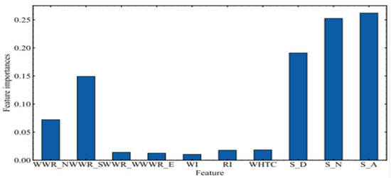
Figure 1.
Analysis of the importance of shading components.
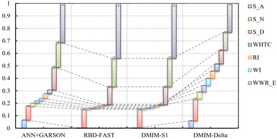
Figure 2.
Sensitivity analysis of shading components.
According to the analysis of the importance of the shading components, the importance of the parameters of the shading components is much higher than that of the building window-to-wall ratio, the thickness of the roof insulation layer, the comprehensive heat transfer coefficient of the external windows, and the parameters of the envelope structure [4]. The order of importance from high to low is window-to-wall ratio in the south (WWR_S), window-to-wall ratio in the north (WWR_N), and window heat transfer coefficient (WHTC); according to the sensitivity analysis of the sunshade components, the sensitivity of the sunshade components in the multi-parameter analysis accounts for about 60% of the total.
Bruhwiler studied the radiative heat transfer characteristics of 26 bicycle helmets and their associated sun visors were evaluated using a thermally simulated head shape in the climate chamber to evaluate their ability to protect the wearer from the sun, which showed that all the helmets of the study resisted 50–75% of the radiant heat in the case of no visor and resisted 65–85% of radiant heat in the case of a visor [5]. With the development of computational fluid dynamics technology, Qing et al. used ecological building ECOTECT simulation software analysis of the influence of a sun visor on the solar radiation in a university building, the radiation changes in the sun visor in the reading room were analyzed, and the corresponding sun visor adjustment control strategy was given [6]. Huo et al. conducted on-site comparison tests in a cold area of China by comprehensively studying the effects of external shading on the thermospective optical properties of ultra-low energy consumption [7]. The results showed that the outer shading device helped to keep the indoor temperature in the sunside area below the temperature of the reference area in the summer and helped the indoor temperature of the sunshade area to stay below the temperature of the reference area. Ye et al. showed through simulation and experiments that by using high reflective materials, the inner shade can significantly reduce the cold load. If they are used, the reduced cold load of the internal sunshade can even match the outer sun [8]. Sun et al. used simulation software to analyze the indoor fluid environment and energy-saving effects after setting outdoor shading devices [9]. The results showed that through reasonable outdoor sunshade design, the indoor thermal environment and comfort level could be significantly improved while reducing air conditioning energy consumption. Shahdan et al. studied the effects of external sunshade equipment for different configurations on the energy consumption of a case study building [10]. The results showed that the energy consumption of different configurations was significant and was best configured as an egg box sunshade. Alhuwayil et al. analyzed the energy-saving potential and economic feasibility of implementing external passive shading strategies for multi-story hotel buildings under the typical wet hot weather of Saudi Arabia [11]. Studies showed that implementing passive shading strategies can reduce the annual energy consumption of the benchmark building by 20.5%. However, this study was specifically targeted toward the Northern Hemisphere and in the main climate, the proposed sunshade strategy was only available for a given direction. Through further research, it was found that the sunshade components had a significant impact on the energy consumption of the air conditioner. Arifin et al. studied indoor temperature and relative humidity using indoor temperature and relative humidity equipment (Hobo Data Logger) in office rooms that were affected by three different types of shading equipment in Malaysia, focusing on vertical shading, horizontal shading, and egg-crate shading [12].
In many buildings, energy usage can be significantly reduced by adopting passive strategies [13]. Building shading is considered to be an economic and effective passive technology. Many scholars have conducted a series of related research on architectural shading. The shave sunshade is preferably between the sun and the area to be cooled, and the sunshade coefficient is between 0.29–0.33. Existing research has promoted the development of architectural shading, but most studies are universal, mainly concentrated in urban buildings or public buildings [14,15,16,17,18,19]. The external boundary conditions of the building do not consider the impact of various local factors, and it is not possible to adapt to the specific extreme thermal climatic conditions, such as those in Turpan, which cannot be effectively combined with the geographical properties of the building. Moreover, the optimization design of the sunshade member does not take into account the influence of the extreme wind environment; furthermore, the research is mainly concentrated in the southern hot areas, with less research on regional buildings in the Northwest Basin [20,21].
Moreover, wind disasters are the largest part of natural disasters, which will cause great losses and damage to buildings and many aspects of production and life [22]. Turfan has an average wind speed of more than 17 m/s for nearly three months. The effect of wind on an object will affect the structural system and produce wind pressure. The wind that plays a role in structural safety is usually formed by atmospheric movement under conditions of intense activity. The wind-induced displacements have a certain periodicity and change steadily [23]. The software used in this study was ANSYS, where the numerical wind tunnel was simulated using CFD technology; the stress and strain were realized through a workbench; and finally, through the Workbench platform, the fluid–structure coupling was realized. Therefore, in modern buildings, this research can play a guiding role in the design and application of cantilevered external shading components. Through the studies, it can be seen that previous studies on sun visors were still not perfect, the research on the wind load of sun visors was different, and the feasibility analysis of sun visor structures under extreme wind environments was even more lacking. Therefore, for modern buildings, this research can play a guiding role in the design and application of cantilevered external shading components under extreme wind conditions [24].
2. Methodology
In recent years, the rapid development of computers has brought new research breakthroughs to wind engineering. The numerical simulation of computational fluid dynamics is similar to wind tunnel experiments and is called a “Numerical Wind Tunnel (NWT)” [25]. In the process of wind load research using computational fluid dynamics technology, considering the different sizes of turbulence vortices, the degree of convergence and accuracy of the calculation results will be largely affected by the selection method of the turbulence model such that different turbulence models are critical to the accuracy and precision of the numerical simulation of the wind load on the building’s north–south horizontal and vertical sunshades [26]. Among them, the fluid mechanics equation is the basis of the solution [27]. Based on the different scale of the turbulent vortex, the Nmurs equation can obtain the exact solution of the turbulence information of the fluid motion process from the theoretical level [28].
This research was based on ANSYS numerical simulation, which can analyze the deformation or movement of a deformed solid under the action of a fluid load. After establishing a reasonable building model, the fluid–structure coupling technology of the workbench platform and fluid field analysis was adopted. Fluent was used, and Mechanical was used for the solid field analysis. The study used Fluent calculations, and the calculation process used the finite volume method. By comparing the effects of different turbulence models on the accuracy of numerical simulation, and combining with the related research results of various turbulence models at home and abroad [29,30,31], in this study, Reynolds average N-S equations model and standard k-ε turbulence model were selected for numerical wind tunnel simulation. Among them, the turbulence model of the fluid field was the standard k-epsilon model, and the solid field calculation used the finite element method. Through the workbench platform, the wind field was imported into the solid field, and the calculation results of the flow field (pressure field) of Fluent were read by Mechanical, and the equivalent stress, strain, maximum principal stress, and principal elastic strain were calculated, thereby completing the shading component structural safety analysis in wind loads.
Through field investigations, it was found that many renewable energy utilization technologies have been put into use in the Turpan demonstration area, and the comprehensive use of photovoltaic and photothermal technologies has been adopted. The whole demonstration area will be the renewable energy utilization mode of ground source heat pump cooling and heating, microgrid system operation and meteorological observation station operation, new energy bus station, and solar roof photovoltaic power generation.
Through testing the indoor environment data of the Turpan demonstration area, it was found that the indoor thermal environment of modern buildings in Turpan was poor under the action of natural ventilation, and the comfort of the space is largely provided by the active energy supply. In this area, due to the lack of reasonable sunshade components and the large window-to-wall ratio, there are a large number of transparent enclosure structures (such as windows), which leads to some problems in the running state of L equipment. The air conditioning and heating of the building are all in the same group of ground source heat pump units, and the power consumption of this unit is an important embodiment of the overall cooling and heating load of the building. At the same time, under the condition of using solar energy resources in the demonstration area, the energy consumption per unit area of the building for refrigeration was 24.17 kW·h/m2, and the energy consumption for heating was 26.35 kW·h/m2, which was higher than the energy-saving standard of 65%. Therefore, taking scientific and reasonable measures to reduce the adverse effects of solar radiation on buildings is in line with Turpan’s regional policy of promoting new urbanization.
2.1. Optimal Parameter Combination and Numerical Solution Design
2.1.1. Parameter Combination Analysis of Building Orientation and Shading Components
Model construction is the basis of finite element analysis. This article used Rhino software to model a 1:1 full-scale model and import it into ANSYS software for further numerical calculations. There are many kinds of sun visor materials [32]. External sun-shading visors include sun visors, sun-shading roller blinds, awnings, movable shutters, and other types. This study selected C25 reinforced concrete as the sun visor material. The corresponding elastic modulus Ec was 2.8 × 10⁴ MPa, the Poisson’s ratio Vc was 0.2, the density ρc was 2400 kg/m3, and the damping coefficient was 0.05. The size of the building was 23.46 m × 12.06 m × 18.2 m. Due to the difference in the width of different windows, the length of the horizontal sun visor was generally between 1.2 m and 2.0 m, and the length of the outer cantilever was 0.8 m; The cantilever length of the vertical sunshade is 0.6 m, the height was 1.5 m, and the thickness was 0.08 m. The partial schematic diagram is shown in Figure 3.
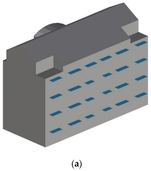
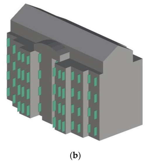
Figure 3.
Schematic diagram of building model with sun visors. (a) Schematic diagram of the south-facing horizontal sun visors; (b) Schematic diagram of the north-facing horizontal sun visors.
2.1.2. Orthogonal Experiment Combination Design
In this research, 10 numerical orthogonal experiments with 5 building orientations under the conditions of southeast wind and northwest wind were carried out, and all working conditions were screened. The specific working conditions are set as shown in the Table 1. The calculation of this project adopted extreme wind conditions, where the wind speed was 28 m/s, and the southeast wind and northwest wind were selected as the dominant wind directions according to the local wind rose chart. Five orientations were selected for the architectural orientation, namely, south, south by west 15, south by west 30, south by east 15, and south by east 30.

Table 1.
Orthogonal experiment table.
2.2. CFD Numerical Wind Tunnel Calculation Parameter Setting
2.2.1. Calculation Parameter Settings
The inlet velocity boundary condition was used at the inlet of the windward side of the calculation basin to define the average wind speed and direction of the incoming flow, the turbulence intensity was set to 5%, and the turbulence viscosity ratio was 10. The calculation adopted the self-maintaining technology of the inlet wind profile, which further improved the accuracy of the numerical simulation. A fully developed outflow boundary condition was used at the outlet of the calculation basin. The ground and building surface adopted the non-slip static wall boundary condition (wall), and the roughness constant was 0.5. Symmetrical free-slip wall boundary conditions (symmetry) were used on the top and sides.
In this study, the turbulence model in the analysis process used the SSTk-w model, which has a good effect on the flow around bluff bodies. The N-S control equation, second-order upwind style, the pressure base solution method, and SIMPLE velocity pressure coupling algorithm were used, and other parameters were the default settings. Based on the above parameter settings, the target building and sunshade components were calculated in the CFD numerical wind tunnel. Furthermore, this study conducted stress and strain analysis on the wind load of the building’s shading components under the action of two maximum wind speeds with a certain turbulence intensity (v = 28.0 m/s, southeast wind and northwest wind).
2.2.2. Computational Domain Selection and Meshing
When using numerical wind tunnels, one should choose a sufficiently large computational domain to minimize the influence of the computational domain’s size on the flow field near the model. At the same time, the selection of the calculated watershed also has a great influence on the analysis time and the accuracy of the results. Therefore, in order to fully develop the flow and considering the calculation efficiency, the calculation domain was 50 m × 80 m × 30 m and the blocking rate was 2.0%.
This model was meshed in advanced meshing software. Because the cantilever structure of the building changed with height, it presented different wind load conditions in the wind environment. Therefore, the meshing process adopted a non-uniform structure with relatively good adaptability. Structured triangular and quadrilateral hybrid mesh patterned mesh were used in the process of generating the grid in order to enable the grid to reproduce the shape of the building, and to obtain more accurate calculation results, the grid sizes of different parts were different. The minimum grid size of the building surface was 1/80 of the height of the building, the grid size at the sun visor was 1/140 of the height of the building, and the maximum grid size of the computational domain was 1/40 of the height of the computational domain
In order to increase the calculation speed, the grid in the middle of the model was relatively sparse; in order to calculate the accuracy, the grid on the left and right sides of the model was encrypted. The grid model of the numerical wind tunnel in this study is shown in Figure 4, in which the grids of the main building and the surface boundary layer were encrypted. After the division was completed, the total number of model body elements was 1,962,800 and the total number of mesh nodes was 342,413.
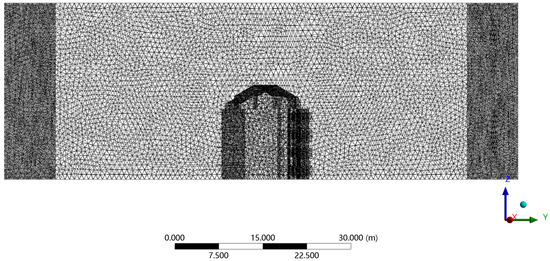
Figure 4.
Computational domain meshing.
2.3. Numerical Simulation of Fluid–Solid Coupling for Structural Analysis of a Sun Visor
The sunshade component of the research object was a reinforced concrete cantilever structure, which had a small solid deformation under a wind load. Therefore, this study adopted the unidirectional fluid–solid coupling method for the wind load calculation, ignoring the influence of the sunshade’s deformation on the fluid field. The finite element analysis road map of structural forces is shown in Figure 5.
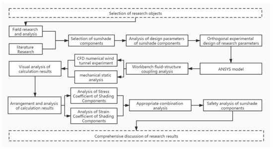
Figure 5.
Road map of finite element analysis of structural forces.
ANSYS software comes with a powerful meshing function; therefore, the building model shown in Figure 4 was imported into the Mechanical computing environment for meshing. The exterior surfaces of the building and the sun visors were all meshed with quadrilateral elements. The grid of the solid field after division is shown in Figure 6 and Figure 7, and then the north–south horizontal and vertical sun visor finite element calculation model was obtained. The number of nodes in the grid was 14,415,953, the number of cells was 3,515,856, the growth rate was 1.2, and the transition ratio was 0.272.
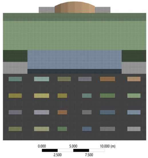
Figure 6.
South-facing horizontal sun visor structure grid.
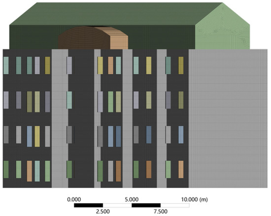
Figure 7.
North-direction vertical sun visor structure grid.
Under strong wind conditions, the load on the sun visor in the calculation model of this study was composed of wind load and dead load. The wind load was the static load of the southeast wind and the northwest wind (28 m/s) under the setting conditions, and the dead load was generated by the gravity of the sun visor itself. In this working condition, the connection between the north–south sunshade and the building structure was a fixed constraint.
3. Analysis Results of Shading Components under Different Working Conditions
Wind Load on Sunshade Components under Changing Building Orientation
In order to facilitate the subsequent analysis, the building’s south-facing horizontal sun visors were divided into I–IV areas according to the height of each floor, and the sun visors of each layer were numbered ①–⑥ in the horizontal direction, as shown in Figure 8; for the same reason, the north-facing vertical sun visors of the building were divided into I–XVIII areas according to the vertical axis, and the sun visors of each layer were numbered ①–④ in the vertical direction, as shown in Figure 9.
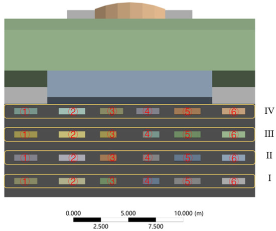
Figure 8.
Schematic diagram of south-facing sun visors.
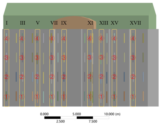
Figure 9.
Schematic diagram of north-facing sun visors.
- (1)
- The southeast wind, where the southward horizontal sun visors changed with the orientation of the building
In the southeast wind conditions, the comparison of the von Mises equivalent stress distribution cloud diagrams of wind loads for different building orientations showed that the building orientation had a greater influence on the equivalent stress of the south-facing horizontal sun visors and the overall coefficient of variation was 96.18%. On the whole, the average value of the equivalent stress of the south-facing horizontal sun visors under the southeast wind condition was 162,422.88 Pa. When the building orientation was true south and south by west 15, the maximum equivalent stresses of the south-facing horizontal sun visors were respectively 377.28 Pa and 577.11 Pa. When the building orientations were south by west 30, south by east 30, and south by east 30, the maximum equivalent stresses of the south-facing horizontal sunshades were 336,220 Pa, 194,540 Pa, and 280,400 Pa, respectively.
From Figure 10a–e, it can be clearly seen that under southeast wind conditions, the building orientation had a certain influence on the equivalent stress distribution of the south horizontal sun visor wind load and the south horizontal sun visor wind load of different building orientations. The distribution area of the effective force was different. When the building was facing south, the maximum equivalent stress was distributed at the sun visor numbered III-①. When the building was oriented south by west 30, the maximum equivalent stress was distributed at the sun visor numbered I-①. When the building orientations were south by west 30, south by east 15, and south by east 30, the equivalent stress of the wind load of the building’s south-facing horizontal sunshade was continuously strengthened with the height of the story and the stress concentration area was at the top of the building’s sunshade. Among them, when the building orientation was south by west 30, the maximum equivalent stress was distributed at the sun visor on the west side of the top floor, numbered IV-①; when the building orientation was south by east 15, the maximum equivalent stress was to the east, distributed at the sun visor numbered IV-④; when the building orientation was south by east 15, the maximum equivalent stress was distributed at the sun visor numbered IV-⑥. These stress concentration distributions should be paid attention to in structural design.
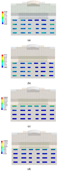
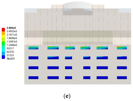
Figure 10.
The southeast wind, where the southward horizontal sun visor changed with the orientation of the building. (a) Cloud map of sun visors in the south direction; (b) Cloud map of the sun visors in the direction of south by west 15; (c) Cloud map of sun visors in the direction of south by west 30; (d) Cloud map of the sun visors in the direction of south by east 15; (e) Cloud map of the sun visors in the direction of south by east 30.
- (2)
- Northwest wind, where the southward horizontal sun visors changed with the orientation of the building
In the northwest wind conditions, the comparison of the von Mises equivalent stress distribution cloud diagrams of wind loads on the sun visors of different buildings showed that the equivalent stress of the south horizontal sun visors under the northwest wind conditions was smaller, with an average value of 6141.3 Pa, which was much smaller than the southeast wind conditions. On the whole, the building orientation had a greater influence on the equivalent stress of the south-facing horizontal sunshade and the overall coefficient of variation was 47.80%. When the building orientation was true south, the maximum equivalent stress of the south-facing horizontal sun visors was 4752.4 Pa. When the building’s orientation was south by west 15 and south by west 30, the maximum equivalent stresses of the south-facing horizontal sunshade were 10,573 Pa and 6335.1 Pa, respectively. When the building orientations were south by east 15 and south by east 30, the maximum equivalent stresses of the south-facing horizontal sunshade were 2571.3 Pa and 6474.7 Pa, respectively.
From Figure 11a–e, it can be clearly seen that under the northwest wind conditions, the building orientation had a certain influence on the equivalent stress distribution law of the wind load on the south horizontal sun visors, and the effects of different building orientations on the south horizontal sun visor wind loads and other effects; the force concentration distribution area was different. When the building was oriented toward the south direction, the equivalent stresses of the bottom I area and the top IV area were larger and the maximum equivalent stress was distributed at the sun visor numbered IV-①. When the building orientations were south by west 15, south by west 30, south by east 15, and south by east 30, the equivalent stresses of the wind loads of the building’s south-facing horizontal sunshade were continuously strengthened with the height of the story, and the stress was concentrated; the area was located at the sun visor of zone IV on the top floor of the building. Among them, when the building orientation was south by west 15, the maximum equivalent stress was distributed at the sunshade on the west side of the top floor, numbered IV-①; when the building orientation was south by west 30, the maximum equivalent stress was distributed on the top floor at the sun visor on the west side numbered IV-③; when the building was oriented south by east 15, the maximum equivalent stress continued to shift to the east and was distributed at the sun visor numbered IV-⑥; when the building was oriented to south by east 30, the maximum equivalent stress was distributed at the sun visor numbered IV-⑥.
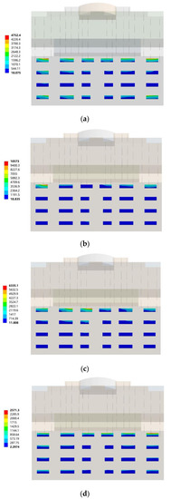
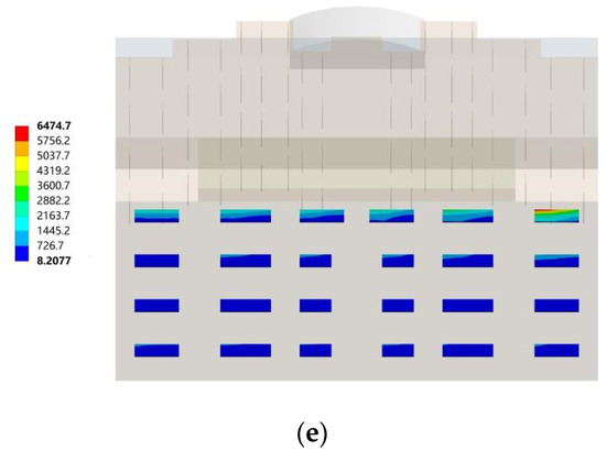
Figure 11.
Northwest wind, where the southward horizontal sun visors changed with the orientation of the building. (a) Clouds of the sun visors in the south direction; (b) Clouds of the sun visors in the direction of south by west 15; (c) Cloud map of sun visors in the direction of south by west 30; (d) Cloud map of sun visors in the direction of south by east 15; (e) Cloud map of the sun visors in the direction of south by east 30.
- (3)
- Northwest wind, where the northward vertical sun visors changed with the orientation of the building
In the northwest wind conditions, through the comparison of the von Mises equivalent stress distribution cloud diagrams of the wind load on the north-facing vertical sun visors of different buildings, it can be seen that the building orientation had a small effect on the equivalent stress of the north-facing vertical sun visors and the overall coefficient of variation was 26.01%. On the whole, the average value of the equivalent stress of the northward vertical sun visors under the northwest wind condition was 133,252.4 Pa. When the building was facing south, the maximum equivalent stress of the north-facing vertical sunshade was 152,790 Pa. When the orientations of the building were south by west 15 and south by west 30, the maximum equivalent stresses of the north-facing vertical sunshades were 139,130 Pa and 151,160 Pa, respectively. When the building orientations were south by east 15 and south by east 15, the maximum equivalent stresses of the north-facing vertical sunshade were 72,022 Pa and 151,160 Pa, respectively.
From Figure 12a–e, it can be seen that under northwest wind conditions, the building orientation had a certain effect on the equivalent stress distribution of the north vertical sun visor wind load. The equivalent stresses of the north vertical sun visor wind loads for different building orientations and the concentrated distribution areas were different. In the northwest wind condition, the equivalent stress of the wind load is concentrated on the north vertical sun visors of the building and the equivalent stress concentration area depended on the angle between the wind direction and the building. When the building was facing south, the wind angle was 45°, the equivalent stress was concentrated at both ends of the building, and the maximum equivalent stress was distributed at the sun visor numbered XVIII-②. When the building was oriented south by west 15, the wind angle was 60° at this time, the equivalent stress was concentrated at both ends of the building, and the maximum equivalent stress was distributed at the sun visor numbered I-①. When the building was facing south by west 30, the wind angle was 75° at this time, the equivalent stress was concentrated at both ends of the building, and the maximum equivalent stress was distributed at the sun visor numbered I-①. When the building was oriented south by east 15, the wind angle was 30°at this time, the equivalent stress concentration position shifted to the middle of the building, and the maximum equivalent stress was distributed at the sun visor numbered XIV-③. When the building orientation was south by east 15, the wind angle was 15° at this time, the equivalent stress was concentrated in the middle part of the building, the equivalent loads of the sun visors on each floor were relatively large, and the maximum equivalent stress was distributed at the sun visor numbered XII-①. When designing the structure, attention should be paid to the distribution of these stress concentrations.
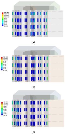
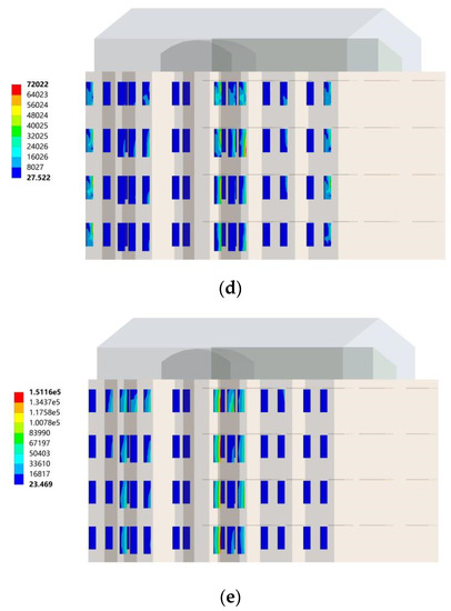
Figure 12.
Northwest wind, where the northward vertical sun visors changed with the orientation of the building. (a) Cloud map of the sun visors in the south direction; (b) Cloud map of the sun visors in the direction of south by west 15; (c) Cloud map of sun visors in the direction of south by west 30; (d) Cloud map of the sun visors in the direction of south by east 15; (e) Cloud map of the sun visors in the direction of south by east 30.
- (4)
- Southeast wind, where the northward vertical sun visors changed with the orientation of the building
In the southeast wind conditions, through the comparison of the von Mises equivalent stress distribution cloud diagrams of the wind loads on the north-facing vertical sun visors of different buildings, it can be seen that the building orientation had a great influence on the equivalent stress of the north-facing vertical sun visors and the overall coefficient of variation was 115.75%. On the whole, compared with the northwest wind condition, the equivalent stress of the north vertical sun visors under the southeast wind condition was smaller and the average value was only 6237.8 Pa. When the building orientation was true south, the maximum equivalent stress of the south-facing horizontal sun visor was 893.76 Pa. When the orientations of the building were south by west 15 and south by west 30, the maximum equivalent stresses of the south-facing horizontal sunshades were 1170.8 Pa and 5714.1 Pa, respectively. When the building orientations were south by east 15 and south by east 30, the maximum equivalent stresses of the south-facing horizontal sunshades were 4840.4 Pa and 18,570 Pa, respectively.
In summary, the equivalent stresses of the wind load of the building’s southward horizontal sunshades under the southeast wind condition were significantly greater than its value under the northwest wind condition. Therefore, the stress concentration areas of the south-facing horizontal sun visors of buildings under the southeast wind conditions should be paid attention to in the structural design. The equivalent stress of the wind load of the building’s northward vertical sunshade under the northwest wind condition was significantly greater than its value under the southeast wind condition. Therefore, the stress concentration areas of the north-facing vertical sun visors of buildings under northwest wind conditions should be paid attention to in the structural design, as shown in Figure 13.
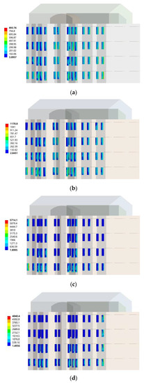
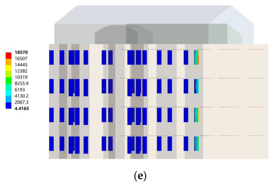
Figure 13.
Southeast wind, northward vertical sun visor changes with the orientation of the building. (a) Cloud map of sun visors in the south direction; (b) Sun visor cloud map in the direction of south by west 15; (c) Cloud map of sun visors in the direction of south by west 30; (d) Cloud map of the sun visor in the direction of south by east 15; (e) Cloud map of sun visors in the direction of south by east 30.
4. Discussion
4.1. Appropriate Combination form Analysis and Discussion
In order to avoid the occurrence of wind disasters in extreme convective weather, it is necessary to reasonably avoid wind load damage to the external shading components of the building when designing buildings in Turpan, where a reasonable combination of building orientation and shading type should be selected. Therefore, the numerical experiment results of the von Mises equivalent stress of wind loads on the south-facing horizontal sun visors and the north-facing vertical sun visors under 10 working conditions are summarized in Table 2. The maximum equivalent stress of a southward horizontal sun visor was 336,220 Pa, the minimum was 377.28 Pa, and the average was 84,279.39 Pa. The maximum equivalent stress of a north vertical sun visor was 152,790 Pa, the minimum was 839.76 Pa, and the average was 68,590.71 Pa.

Table 2.
Von Mises equivalent stress of wind load on sun visors under 10 working conditions.
- (1)
- The best architectural orientation of a south-facing horizontal sun visor
The maximum equivalent von Mises stress under wind loading of the south horizontal sun visor under various working conditions is shown in Figure 14 and the optimal equivalent stress of working conditions No.1–No.4 and No.6/No.8/No.10 are shown in the figure. First of all, this shows that for the different building orientations in No.5, under the northwest wind conditions, the equivalent stresses of the wind load of the south-facing horizontal sun visors were all smaller. Second, the building orientation corresponding to No.1 and No.2 working conditions was south, and the building orientation corresponding to No.3 and No.4 working conditions was south by west 15, whether it was in the southeast wind condition or in the northwest. Under wind conditions, the equivalent stress of the wind load was relatively small. However, for other building orientations, the south-facing horizontal sun visors were greatly affected by the wind direction, where the maximum equivalent stress under the southeast wind condition was significantly greater than its value under the northwest wind condition. Therefore, for the south-facing horizontal sunshade, when the building orientation was true south and south by west 15, this was the most suitable combination.
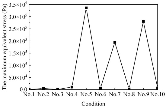
Figure 14.
Maximum equivalent stress under 10 working conditions of south-facing horizontal sun visors.
- (2)
- The best architectural orientation of the north-facing vertical sun visor
The maximum equivalent von Mises stress from wind loading of north horizontal sun visors under various working conditions is shown in Figure 15 and the optimal working conditions were No.1/No.3/No.5/No.7/No.8/No.9. The equivalent stress was small. First of all, this shows that for the five different building orientations, the equivalent stresses of the wind load on the north-facing vertical sun visors were all relatively small under the southeast wind conditions. Second, No.7 and No.8 respectively corresponded to the southeast wind and northwest wind when the building was oriented south by east 15, and the maximum equivalent stress of the wind load was relatively small. However, for other building orientations, the northward vertical sunshades were greatly affected by the wind direction, and the maximum equivalent stress under the northwest wind condition was significantly greater than its value under the southeast wind condition. Therefore, for the north-facing vertical sun visors, when the building orientation was south by east 15, this was the most suitable combination form.
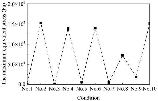
Figure 15.
Maximum equivalent stress of north vertical sun visors under 10 working conditions.
- (3)
- The best architectural orientation of the comprehensive north–south sunshades
Based on the above analysis, it can be seen that the south-facing horizontal sun visors and the north-facing vertical sun visors had their respective best combinations of architectural orientations. However, in actual situations, the north–south sun visors are all necessary building components; therefore, they need to be integrated by considering the south-facing horizontal sun visor and the north-facing vertical sun visor to find the best combination of sun visors and building orientation. Figure 16 depicts the maximum von Mises equivalent stress of the sun visors when the five building orientations were in the southeast wind and northwest conditions. The comparison shows that when the building orientations were south and south by west 15, the comprehensive maximum equivalent stress of the north–south sun visor was smaller. Therefore, when the south-facing horizontal sun visors and the north-facing vertical sun visors were used at the same time, the best architectural orientation was south by west 15, followed by the south direction.
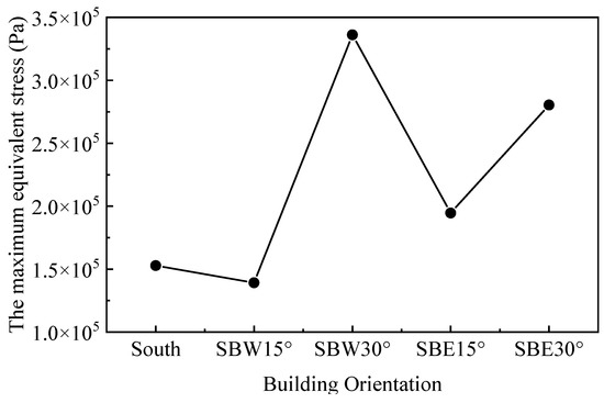
Figure 16.
The comprehensive maximum equivalent stress of 5 building orientations under 2 wind direction conditions.
4.2. The Structural Safety Analysis of Sunshade Components under Wind Loading
Under the action of wind loading, the structural safety of the sunshade construction needs to be paid attention to; otherwise, it will cause damage to the sunshade or the building structure, affect the use of the building, and cause harm to the personal safety of people moving around the building. Therefore, the most unfavorable situation of structural safety under various working conditions needs to be paid attention to. Based on the above analysis, this study further calculated the maximum principal stress and maximum principal elastic strain under 10 working conditions.
Figure 17 and Figure 18 show the maximum principal stress cloud diagram of the south-facing horizontal sunshades with different building orientations under two wind conditions. When the most stressed part appears below, it means that the root of the lower surface of the horizontal sun visor was stressed; when the most stressed part appears on the top, it means that the root of the horizontal sun visor was stressed.
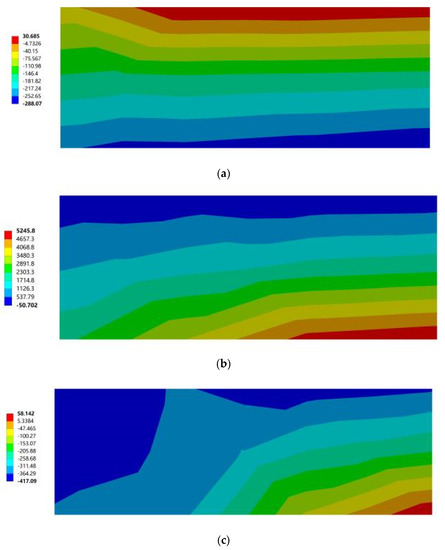
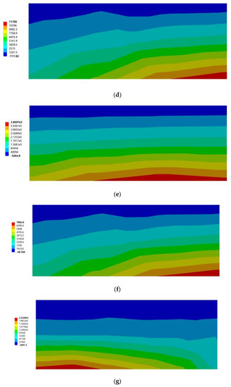
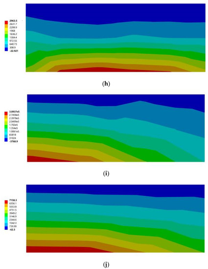
Figure 17.
The maximum principal stress cloud diagram of the southward horizontal sun visor. (a) South to southeast wind. (b) South to northwest wind. (c) South by west 15 to southeast wind. (d) South by west 15 to northwest wind. (e) South by west 30 to southeast wind. (f) South by west 30 to northwest wind. (g) South by east 15 to southeast wind. (h) South by east 15 to northwest wind. (i) South by east 30 to southeast wind. (j) South by east 30 to northwest wind.
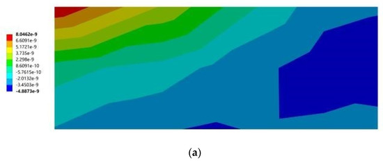
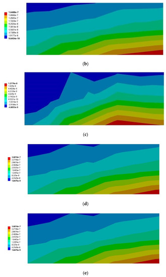
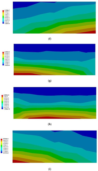
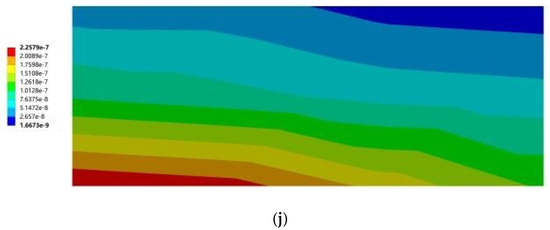
Figure 18.
Cloud diagram of the maximum elastic principal strain of southward horizontal sun visors. (a) South to southeast wind. (b) South to northwest wind. (c) South by west 15 to southeast wind. (d) South by west 15 to northwest wind. (e) South by west 30 to southeast wind. (f) South by west 30 to northwest wind. (g) South by east 15 to southeast wind. (h) South by east 15 to northwest wind. (i) South by east 30 to southeast wind. (j) South by east 30 to northwest wind.
Figure 19 and Figure 20 show the maximum principal elastic strain cloud diagrams of the southward horizontal sunshades with different building orientations under two wind conditions. When the most strained part appears below, it means that the root of the lower surface of the horizontal sun visor was stressed; when the most strained part appears on the top, it means that the root of the horizontal sun visor was stressed.
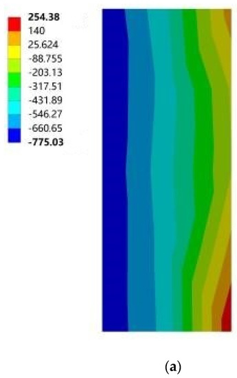


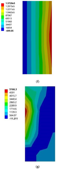

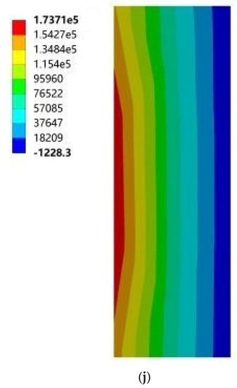
Figure 19.
Maximum principal stress cloud diagram of north vertical sun visors. (a) South to southeast wind. (b) South to northwest wind. (c) South by west 15 to southeast wind. (d) South by west 15 to northwest wind. (e) South by west 30 to southeast wind. (f) South by west 30 to northwest wind. (g) South by east 15 to southeast wind. (h) South by east 15 to northwest wind. (i) South by east 30 to southeast wind. (j) South by east 30 to northwest wind.
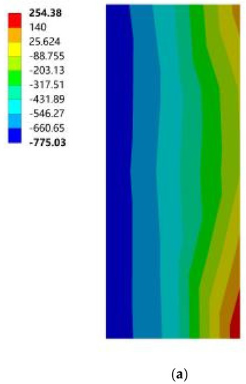
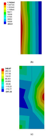

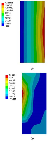

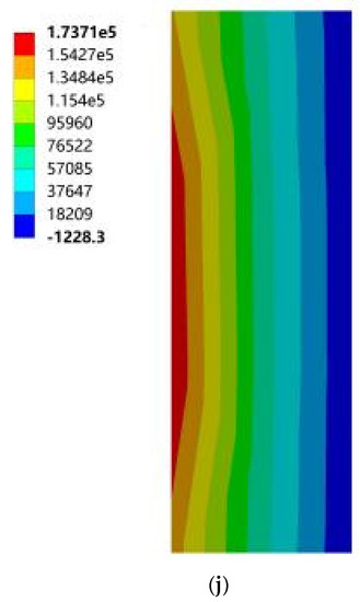
Figure 20.
Cloud diagram of the maximum elastic principal strain of southward horizontal sun visors. (a) South to southeast wind. (b) South to northwest wind. (c) South by west 15 to southeast wind. (d) South by west 15 to northwest wind. (e) South by west 30 to southeast wind. (f) South by west 30 to northwest wind. (g) South by east 15 to southeast wind. (h) South by east 15 to northwest wind. (i) South by east 30 to southeast wind. (j) South by east 30 to northwest wind.
Based on the above 18 cloud diagrams, Table 3 summarizes the specific values corresponding to the maximum principal stress and maximum principal elastic strain of the south-facing horizontal sun visors and the north-facing vertical sun visors under 10 working conditions. It can be seen from Table 3 that, according to 4.2.3 of the “Code for Design of Concrete Structures” GB 50010-2010, the standard value of C25 concrete axial compressive strength is 16.7 MPa and the standard value of compressive strength is 1.78 MPa. In general, the maximum tensile strain of concrete is 1 × 10⁻⁴ and the maximum compressive strain is 3.3 × 10⁻⁴. The data in the comparison Table 3 shows that the maximum principal stress of the sun visor under all working conditions was 0.39 MPa, which is much smaller than the tensile strength of C25 concrete. In the same way, the maximum principal elastic strain of the sun visor under all working conditions was 0.12 × 10⁻⁴ according to the provisions of 4.2.3 in China’s current “Code for Design of Concrete Structures” GB 50010-2010, which is much smaller than the maximum strain value of concrete. Therefore, the wind load under the working conditions of this study had no significant impact on the safety of the concrete structure. However, considering the dynamic abrupt changes and duration characteristics of wind loads in nature, the wind loads in actual use may exceed the set range in this study. Therefore, in buildings using concrete external shading components, it is still necessary to strengthen the shading by paying attention to the stress concentration of the slab in the structural design when necessary. According to the wind tunnel test research conducted by the State Key Laboratory of Civil Engineering and Disaster Prevention of Tongji University on the wind load of horizontal cantilever sunshades, the results showed that the maximum value of the most unfavorable net wind pressure of the horizontal cantilever sunshades of high-rise buildings appeared on the top sunshade on the board [33]. This confirmed the wind pressure distribution and the force of the horizontal sun visor in this study, but the test did not consider the structural safety analysis of the cantilever sun visor under multiple parameters. On this basis, this study further considered the structural safety performance analysis of the sunshade components under different building orientations, different sunshade forms, and different mechanical parameters, and the results were summarized, analyzed, and discussed accordingly, and some practical results were obtained. Finally, there were some valuable conclusions from the project.

Table 3.
Maximum principal stress and maximum principal elastic strain under 10 working conditions.
5. Conclusions
In this study, by considering the wind load characteristics of sunshade components and the structural safety of sunshade components on the structure, flow field simulations in an extreme wind environment were carried out to undertake a structural safety analysis of building exterior sunshade components. By demonstrating the importance and sensitivity of the sunshade component, the importance of the parameters of the sunshade component was much higher than the window-to-wall ratio, the thickness of the roof insulation layer, the comprehensive heat transfer coefficient of the outer window, and the parameters of the envelope structure. The sensitivity of the sunshade component accounted for about 60% of the total proportion of multiple parameters; therefore, it can be seen that the sunshade component is the most important and sensitive part of the influence of building performance in Turpan. However, the Turpan area has a bad wind environment, which causes great damage to the building components. Therefore, considering the safety of sunshade components in a wind environment was the focus of this study.
By analyzing the influence of different forms of sunshades on air conditioning energy consumption, heating energy consumption, and comfort in the Turpan area, the structural design parameters of different forms of sunshades in the Turpan area were obtained, as well as the dimensions of cantilevered exterior sunshades suitable for buildings in the Turpan area. The length of the horizontal sunshade was between 1.2 m and 2.0 m, the size of the external cantilever was 0.8 m, the length of the vertical sunshade was 0.6 m, the height was 1.5 m, and the thickness was 0.08 m. The analysis showed the importance of setting sunshade structures in the Turpan area. Using the finite element method for the fluid–structure interaction analysis of the shading component under the environment of extreme wind, and adopting a full-size scale modeling method for the main body of the building to ensure the accuracy of the results of the analysis, solutions for different building orientations for the south and the north building outside shading, cantilever horizontal visors, and vertical wind load stresses and strains of the visors were obtained. In this study, the maximum principal stress σ max and maximum principal elastic strain ε max were calculated under 10 working conditions. According to the solution results, the maximum principal stress of the sunshade under all working conditions was 0.39 MPa, which is far less than the tensile strength of C25 concrete. The calculated maximum principal elastic strain of the sunshade was 0.12 × 10⁻⁴, which is far less than the maximum strain of concrete. Therefore, the wind load in this study had no great influence on the structural safety of concrete.
Author Contributions
Formal analysis, H.Z.; resources, Z.W.; data curation, P.N.; writing—original draft preparation, C.L.; project administration, W.W. All authors have read and agreed to the published version of the manuscript.
Funding
This subject was supported by the Xinjiang Uygur Autonomous Region University Scientific Research Program Key Project (XJEDU2019I006), and the project name was “Research on the Heat Protection Mechanism and Structural System of Buildings in Turpan Region”.
Conflicts of Interest
The authors declare no conflict of interest.
References
- Yang, L.; Fu, R.; He, W.; He, Q.; Liu, Y. Adaptive thermal comfort and climate responsive building design strategies in dry–hot and dry–cold areas: Case study in Turpan, China. Energy Build. 2020, 209, 109678. [Google Scholar] [CrossRef]
- Sarkar, A.; Bose, S. Evaluating the Effect of Building Envelope on Thermal Performance of Houses in Lower Himachal Pradesh. In From Poverty, Inequality to Smart City; Springer: Singapore, 2016; pp. 143–159. [Google Scholar] [CrossRef]
- Chen, J.; Yang, L.; Luo, Z.X. Research on indoor thermal environment of residential buildings in Turpan. J. Xi’an Univ. Archit. Technol. 2019, 51, 578–583. [Google Scholar] [CrossRef]
- Ni, P.; Wang, W.; Zheng, H.; Ji, W. Sensitivity analysis of design parameters of envelope enclosure performance in the dry-hot and dry-cold areas. In Applied Mathematics and Nonlinear Sciences; Sciendo: Warsaw, Poland, 2021. [Google Scholar] [CrossRef]
- Brühwiler, P. Radiant heat transfer of bicycle helmets and visors. J. Sports Sci. 2008, 26, 1025–1031. [Google Scholar] [CrossRef] [PubMed]
- Qing, L.; Run, G.; Bo, J.; Shiming, W. University Library External Window Sunshade Device Simulation Analysis and Optimization Design. Proc. Eng. 2017, 174, 1196–1201. [Google Scholar] [CrossRef]
- Huo, H.; Xu, W.; Li, A.; Cui, G.; Wu, Y.; Liu, C. Field comparison test study of external shading effect on thermal-optical performance of ultralow-energy buildings in cold regions of China. Build. Environ. 2020, 180, 106926. [Google Scholar] [CrossRef]
- Ye, Y.; Xu, P.; Mao, J.; Ji, Y. Experimental study on the effectiveness of internal shading devices. Energy Build. 2016, 111, 154–163. [Google Scholar] [CrossRef]
- Sun, N.; Cui, Y.; Jiang, Y.; Li, S. Lighting and Ventilation-based Building Sun-Shading Design and Simulation Case in Cold Regions. Energy Proc. 2018, 152, 462–469. [Google Scholar] [CrossRef]
- Shahdan, M.S.; Ahmad, S.S.; Hussin, M.A. External shading devices for energy efficient building. In IOP Conference Series: Earth and Environmental Science; IOP Publishing: Bristol, UK, 2018; Volume 117, p. 012034. [Google Scholar] [CrossRef]
- Alhuwayil, W.K.; Mujeebu, M.A.; Algarny, A.M.M. Impact of external shading strategy on energy performance of multi-story hotel building in hot-humid climate. Energy 2018, 169, 1166–1174. [Google Scholar] [CrossRef]
- Arifin, N.A.; Denan, Z. An Analysis of Indoor Air Temperature and Relative Humidity in Office Room with Various External Shading Devices in Malaysia. Proc. Soc. Behav. Sci. 2015, 179, 290–296. [Google Scholar] [CrossRef]
- Amirifard, F.; Sharif, S.A.; Nasiri, F. Application of passive measures for energy conservation in buildings—a review. Adv. Build. Energy Res. 2018, 13, 282–315. [Google Scholar] [CrossRef]
- Xie, J.C.; Xue, P.; Mak, C.M.; Liu, J.P. Balancing energy and daylighting performances for envelope design: A new index and proposition of a case study in Hong Kong. Appl. Energy. 2017, 205, 13–22. [Google Scholar] [CrossRef]
- Noranai, Z.; Azman, A. Potential reduction of energy consumption in public university library. In IOP Conference Series: Materials Science and Engineering; IOP Publishing: Bristol, UK, 2017; Volume 243, p. 12023. [Google Scholar] [CrossRef]
- Liu, S.; Kwok, Y.T.; Lau, K.K.-L.; Chan, P.W.; Ng, E. Investigating the energy saving potential of applying shading panels on opaque façades: A case study for residential buildings in Hong Kong. Energy Build. 2019, 193, 78–91. [Google Scholar] [CrossRef]
- Li, L.; Qu, M.; Peng, S. Performance evaluation of building integrated solar thermal shading system: Building energy consumption and daylight provision. Energy Build. 2016, 113, 189–201. [Google Scholar] [CrossRef]
- Bellia, L.; Marino, C.; Minichiello, F.; Pedace, A. An Overview on Solar Shading Systems for Buildings. Energy Proc. 2014, 62, 309–317. [Google Scholar] [CrossRef]
- Kim, S.-H.; Shin, K.-J.; Choi, B.-E.; Jo, J.-H.; Cho, S.; Cho, Y.-H. A Study on the Variation of Heating and Cooling Load According to the Use of Horizontal Shading and Venetian Blinds in Office Buildings in Korea. Energies 2015, 8, 1487–1504. [Google Scholar] [CrossRef]
- Soflaei, F.; Shokouhian, M.; Abraveshdar, H.; Alipour, A. The impact of courtyard design variants on shading performance in hot- arid climates of Iran. Energy Build. 2017, 143, 71–83. [Google Scholar] [CrossRef]
- Dutta, A.; Samanta, A.; Neogi, S. Influence of orientation and the impact of external window shading on building thermal performance in tropical climate. Energy Build. 2017, 139, 680–689. [Google Scholar] [CrossRef]
- Deng, J.; Fang, S.; Lin, X.; Cai, P. Risk Analysis and Protection Strategy of Coastal Urban Construction Project under Extreme Typhoon Climate—A Case Study of Xiamen City. In IOP Conference Series: Earth and Environmental Science; IOP Publishing: Bristol, UK, 2020; Volume 510. [Google Scholar] [CrossRef]
- Ma, J.; Zhou, D.; Han, Z.; Zhang, K.; Nguyen, J.; Lu, J.; Bao, Y. Numerical Simulation of Fluctuating Wind Effects on an Offshore Deck Structure. Shock Vib. 2017, 2017, 3210271. [Google Scholar] [CrossRef]
- Rostam-Alilou, A.A.; Zhang, C.; Salboukh, F.; Gunes, O. Potential use of Bayesian Networks for estimating relationship among rotational dynamics of floating offshore wind turbine tower in extreme environmental conditions. Ocean Eng. 2021, 244, 110230. [Google Scholar] [CrossRef]
- Qu, X.; Zhang, Y.; Lu, X.; Lei, Z.; Zhu, J. The effect of endwall boundary layer and incoming wakes on secondary flow in a high-lift low-pressure turbine cascade at low Reynolds number. Proc. Inst. Mech. Eng. Part G J. Aerosp. Eng. 2019, 233, 5637–5649. [Google Scholar] [CrossRef]
- Thordal, M.S.; Bennetsen, J.C.; Koss, H.H.H. Review for practical application of CFD for the determination of wind load on high-rise buildings. J. Wind Eng. Ind. Aerodyn. 2019, 186, 155–168. [Google Scholar] [CrossRef]
- Wright, N.G.; Easom, G.J.; Hoxey, R.J. Development and validation of a non-linear k-ε model for flow over a full-scale building. Wind. Struct. 2001, 4, 177–196. [Google Scholar] [CrossRef]
- Wissink, J.G. DNS of separating, low Reynolds number flow in a turbine cascade with incoming wakes. Int. J. Heat Fluid Flow 2003, 24, 626–635. [Google Scholar] [CrossRef]
- Majdoubi, H.; Boulard, T.; Fatnassi, H.; Bouirden, L. Airflow and microclimate patterns in a one-hectare Canary type greenhouse: An experimental and CFD assisted study. Agric. For. Meteorol. 2009, 149, 1050–1062. [Google Scholar] [CrossRef]
- Ould Khaoua, S.A.; Bournet, P.-E.; Migeon, C.; Boulard, T.; Chassériaux, G. Analysis of Greenhouse Ventilation Efficiency based on Computational Fluid Dynamics. Biosyst. Eng. 2006, 95, 83–98. [Google Scholar] [CrossRef]
- Teitel, M.; Ziskind, G.; Liran, O.; Dubovsky, V.; Letan, R. Effect of wind direction on greenhouse ventilation rate, airflow patterns and temperature distributions. Biosyst. Eng. 2008, 101, 351–369. [Google Scholar] [CrossRef]
- Babaizadeh, H.; Haghighi, N.; Broun, R.; Asadi, S. Life Cycle Assessment of Common Materials Used for Exterior Window Shadings in Residential Buildings. Proc. Eng. 2015, 118, 794–801. [Google Scholar] [CrossRef][Green Version]
- Quan, Y.; Qiu, H.Z.; Zhang, Z.W.; Gu, M. Wind tunnel test study of wind load on horizontal cantilevered sunshades of high-rise buildings. J. Build. Struct. 2022, 43, 92–97. [Google Scholar] [CrossRef]
Publisher’s Note: MDPI stays neutral with regard to jurisdictional claims in published maps and institutional affiliations. |
© 2022 by the authors. Licensee MDPI, Basel, Switzerland. This article is an open access article distributed under the terms and conditions of the Creative Commons Attribution (CC BY) license (https://creativecommons.org/licenses/by/4.0/).