
Model Test on Approaching the Construction of Multi-Line Overlapping Shield Tunnels for Up- and Down-Crossing

Abstract
:1. Introduction
2. Model Tests
2.1. Testing Material
2.1.1. Derivation of Similarity Criterion
2.1.2. Test Soil
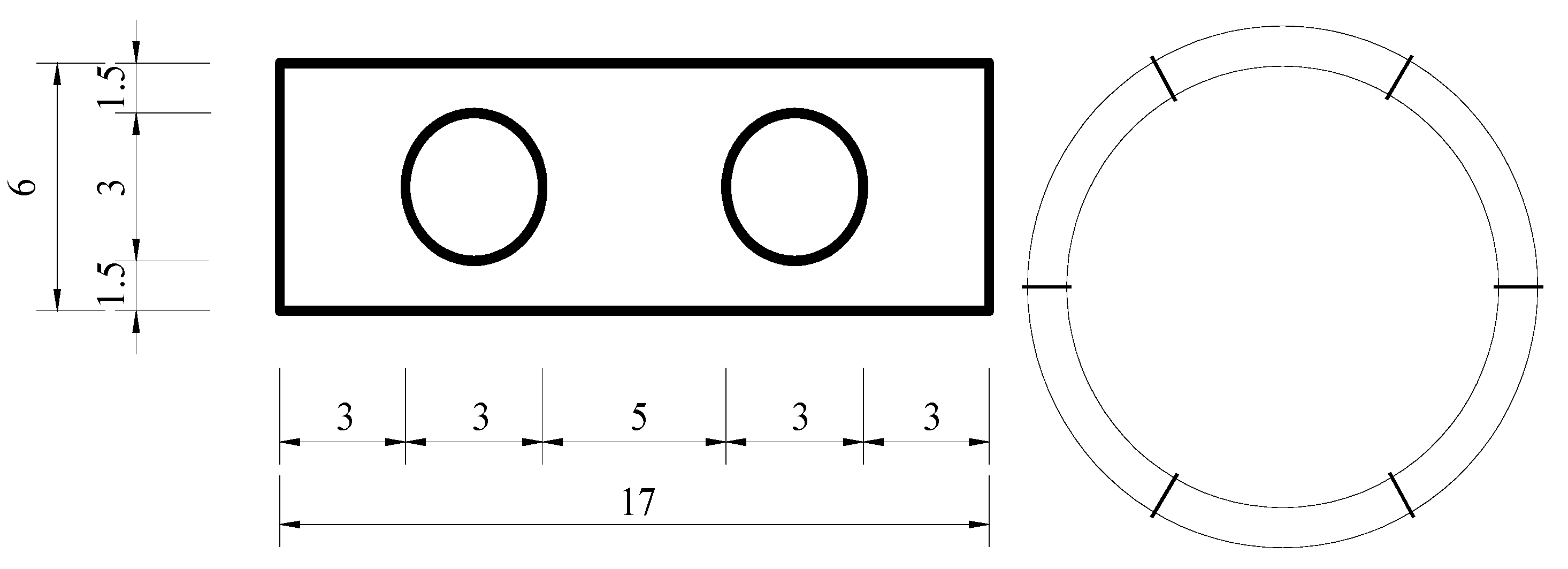
2.1.3. Tunnel Model
2.2. Testing Conditions
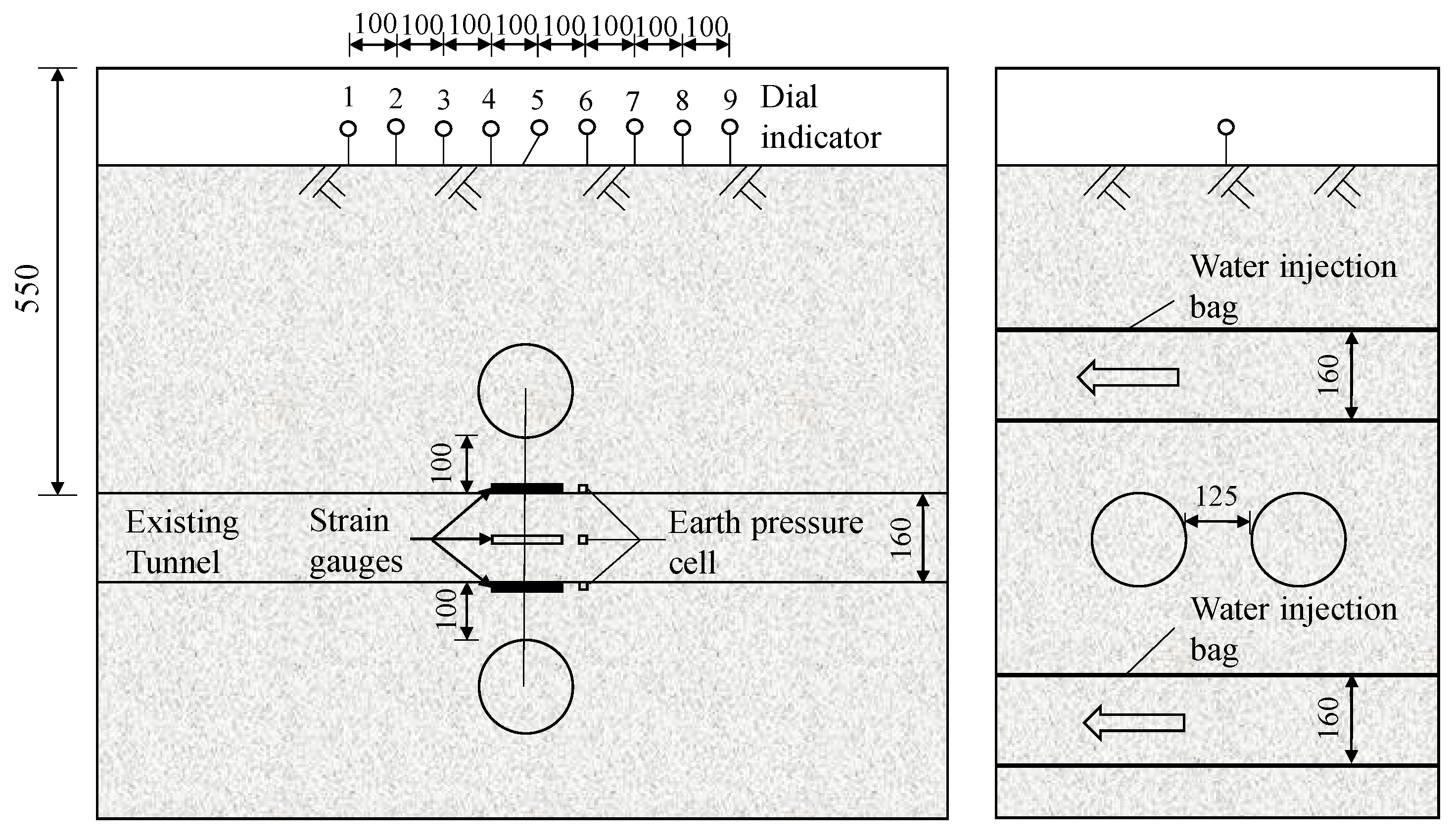
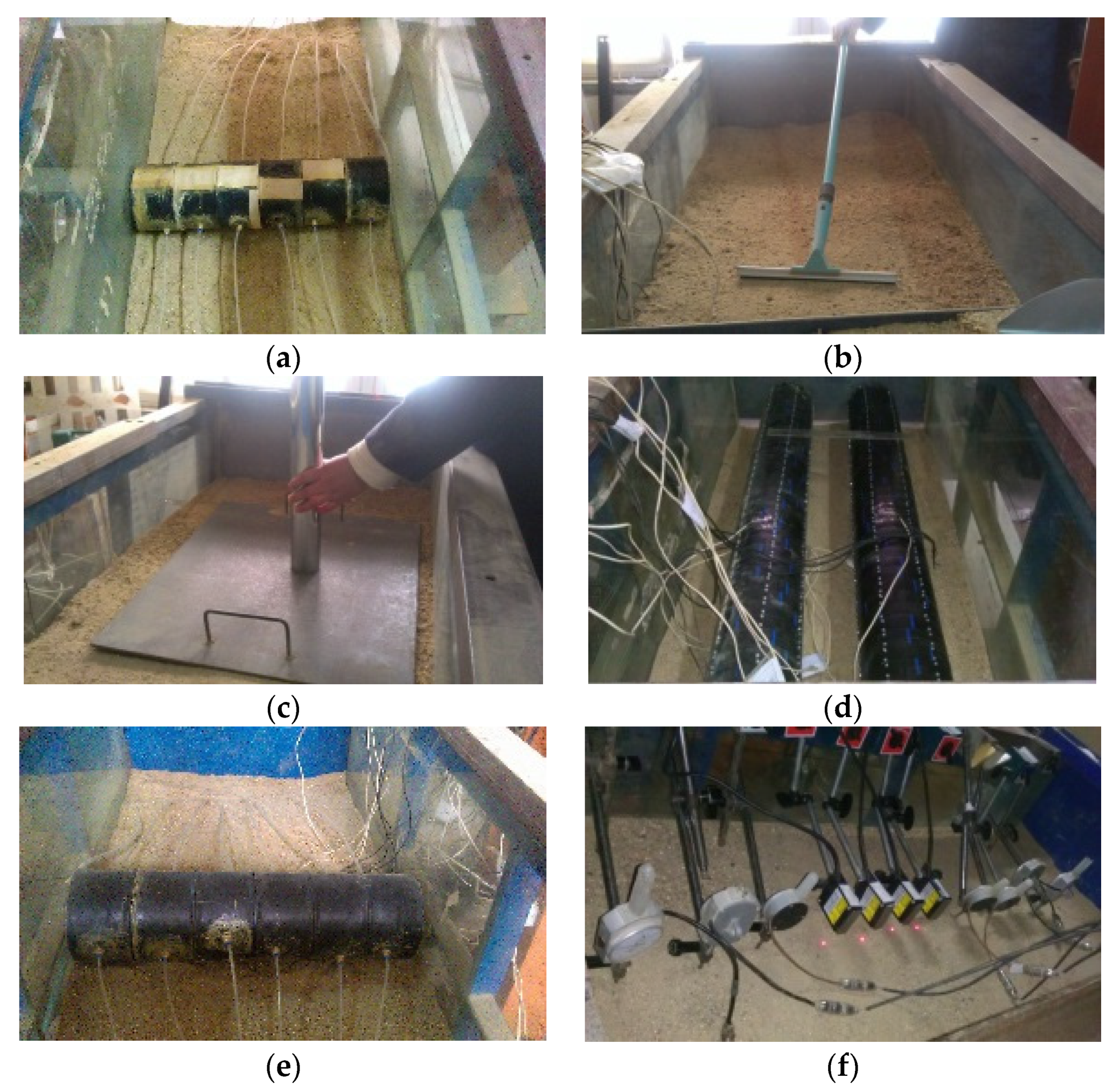
2.3. Testing Process
3. Analysis of Test Results
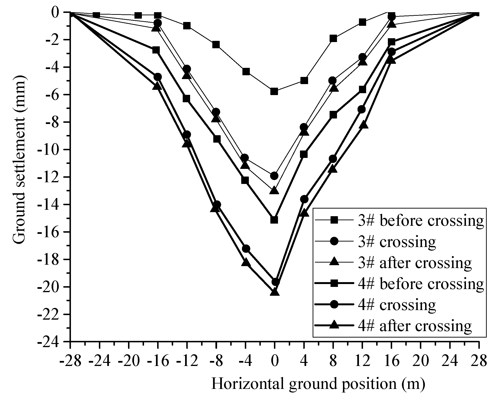
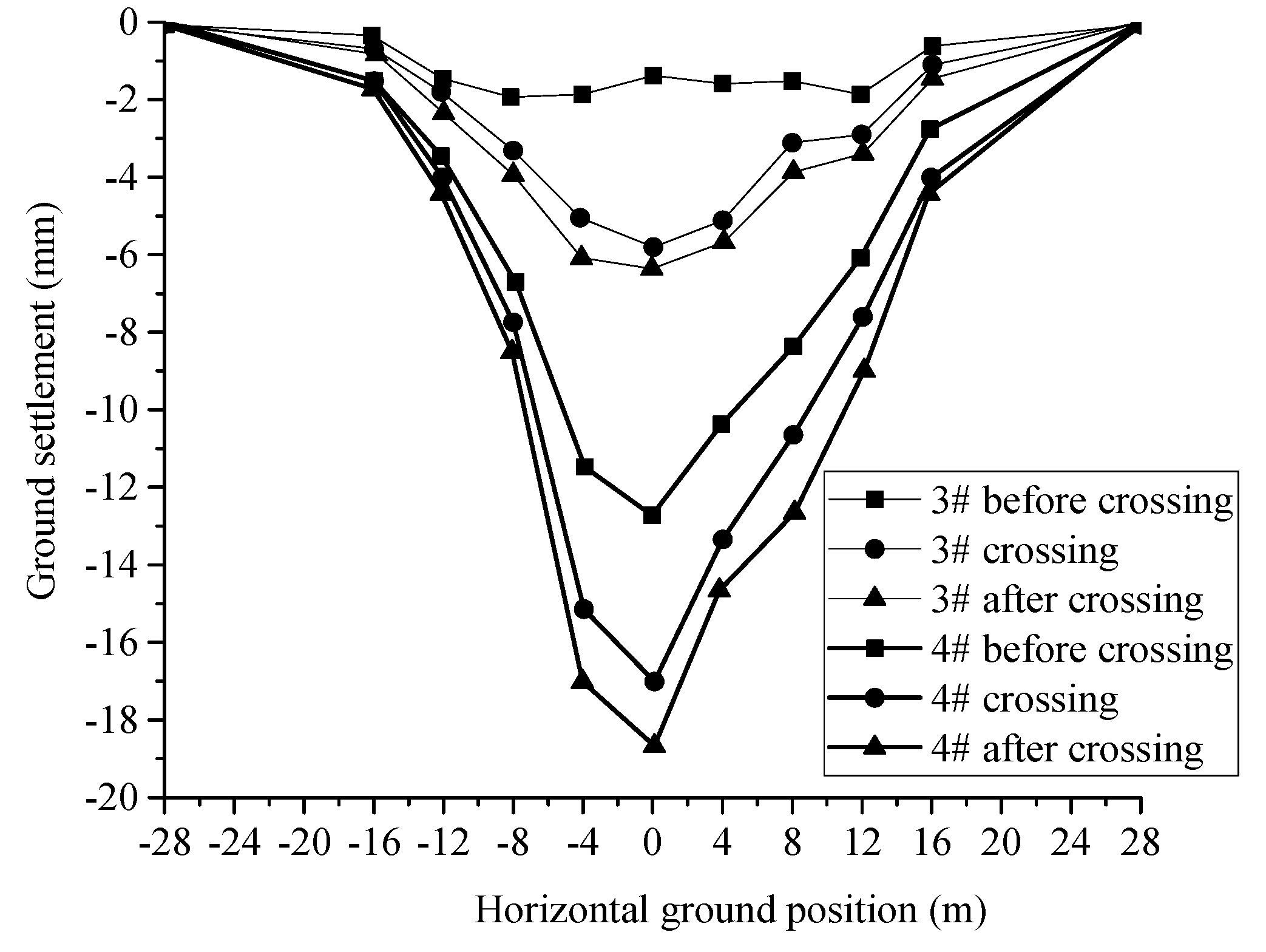
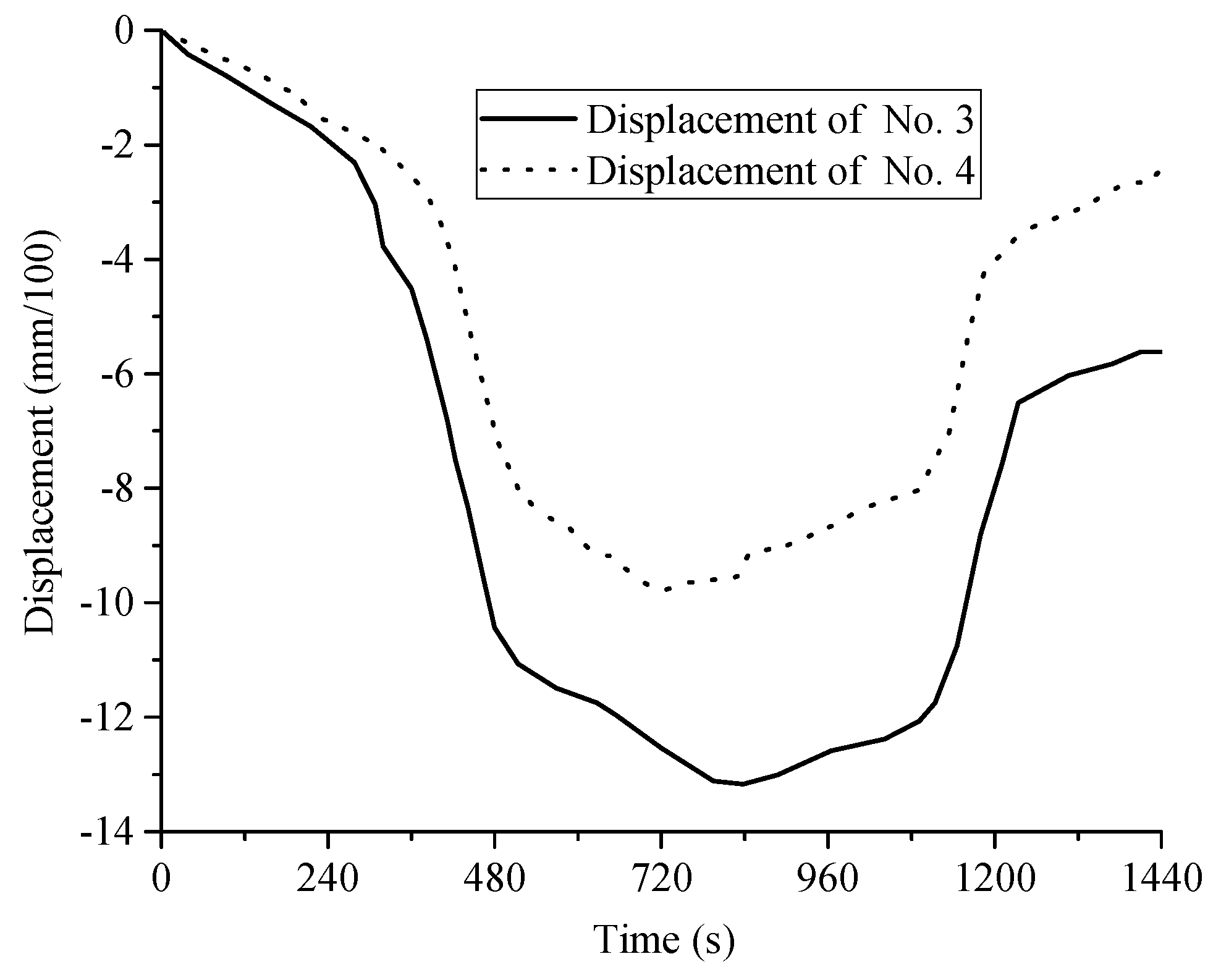
3.1. Analysis of the Surface Settlement
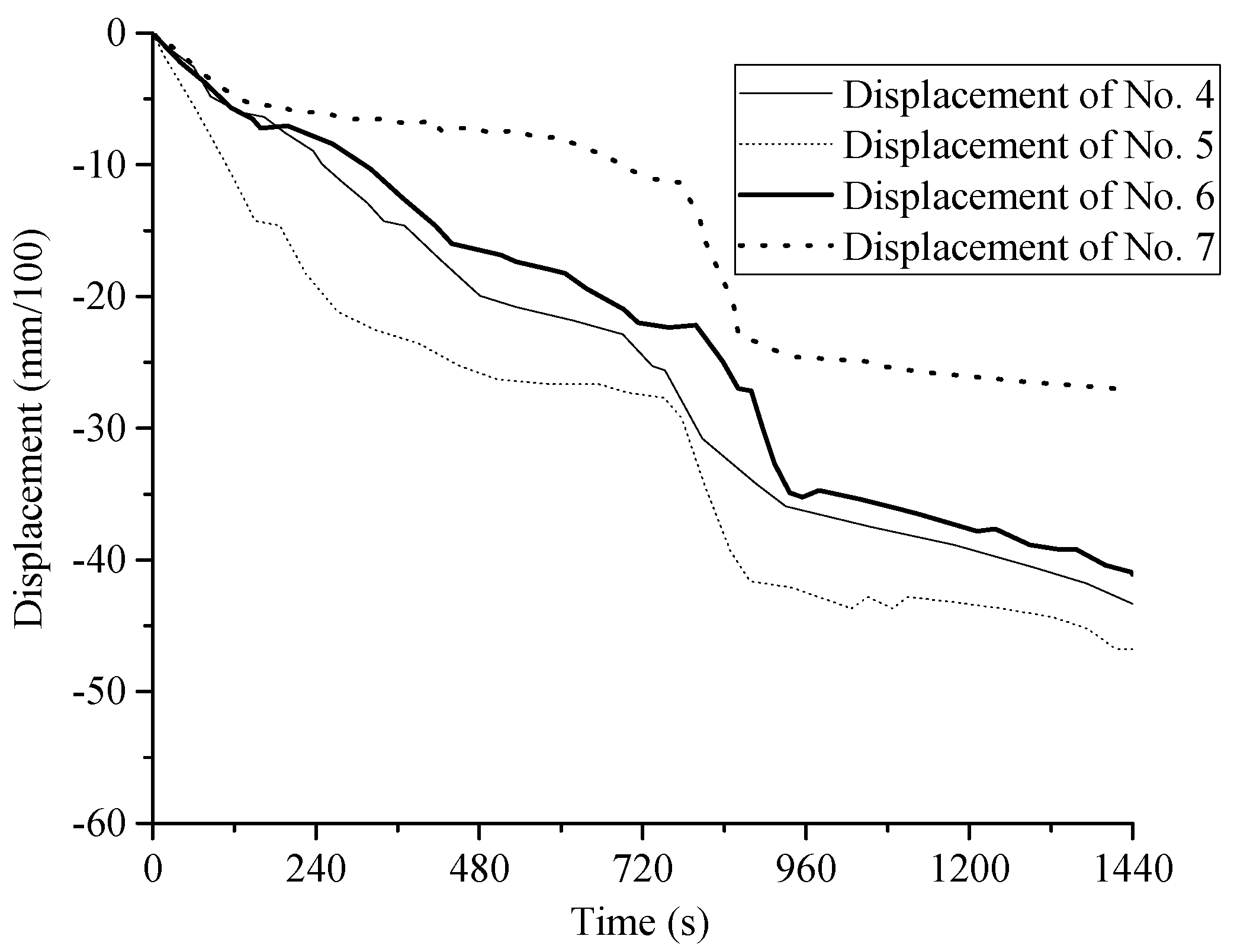
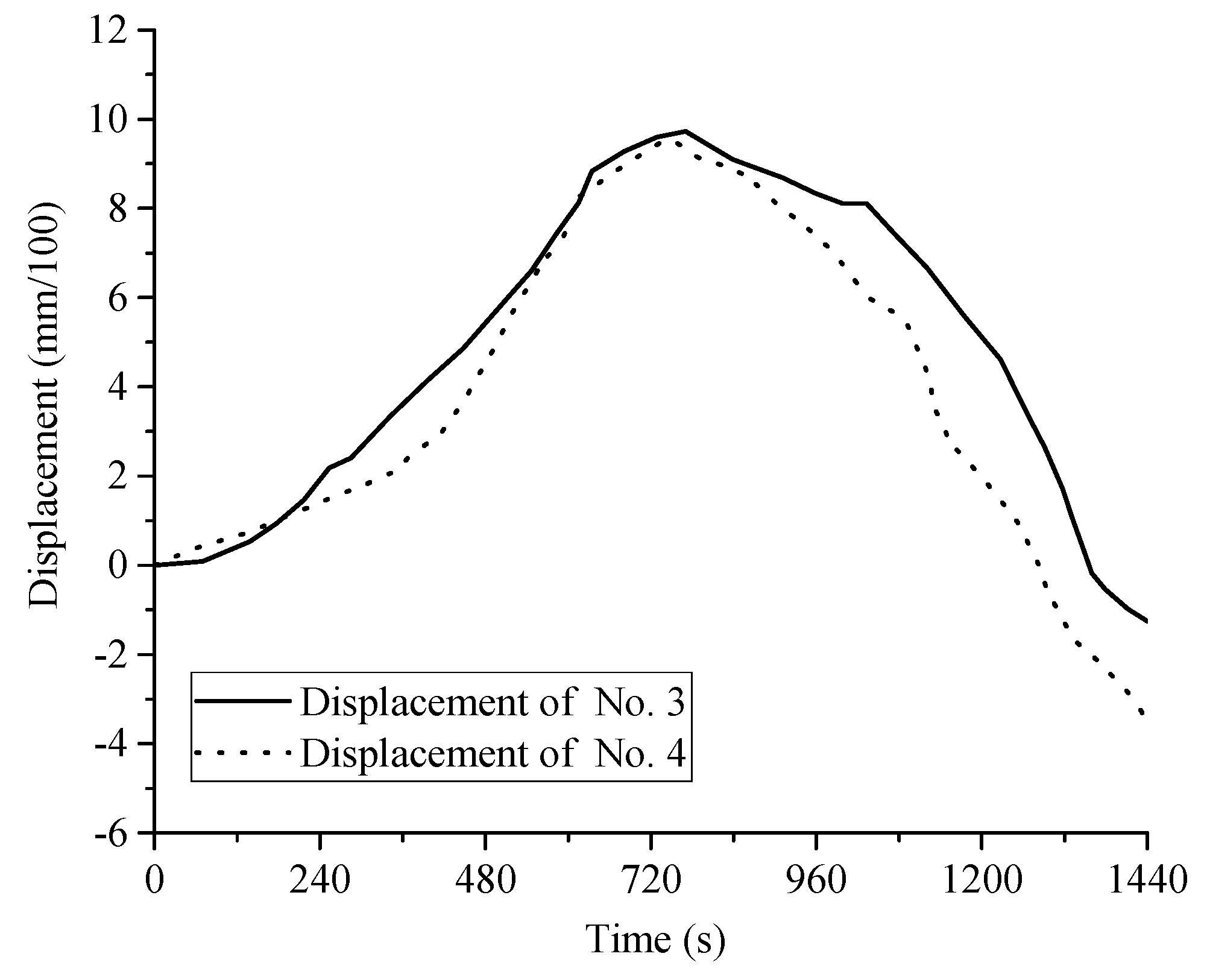
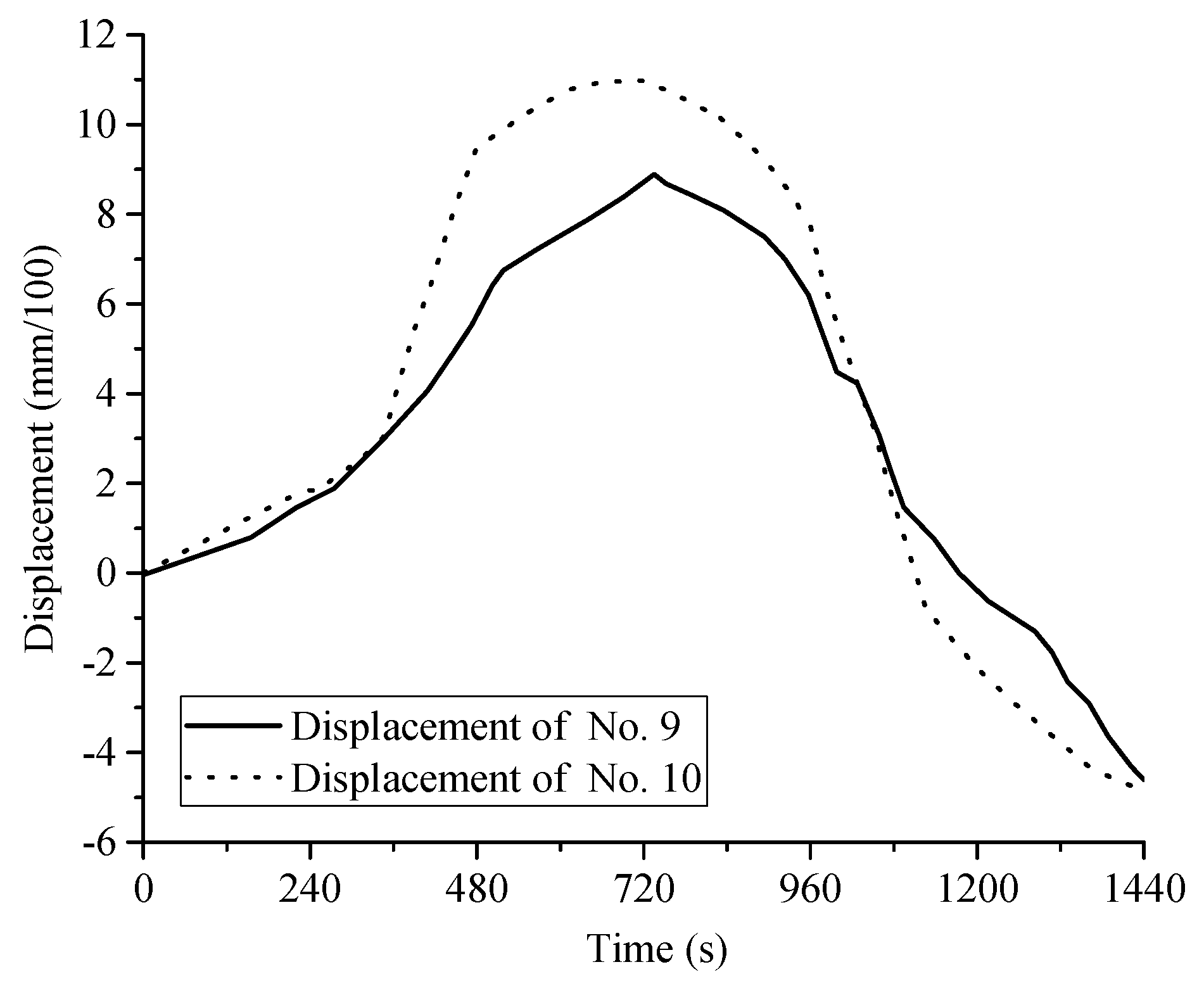
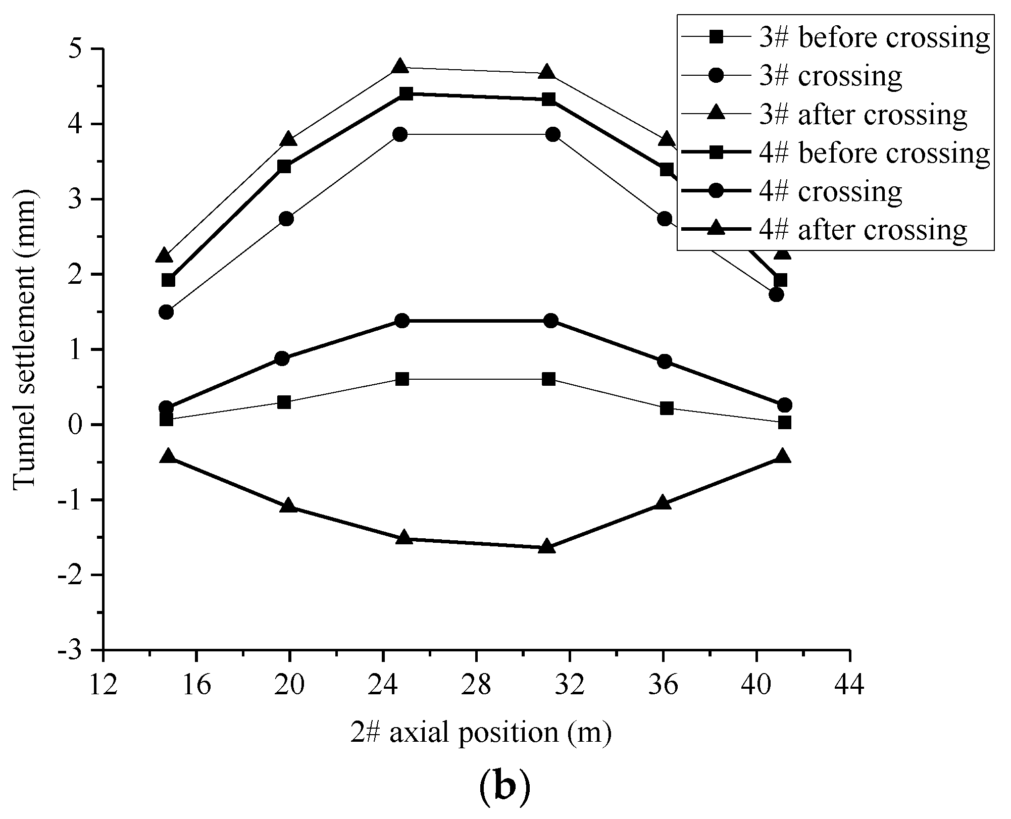
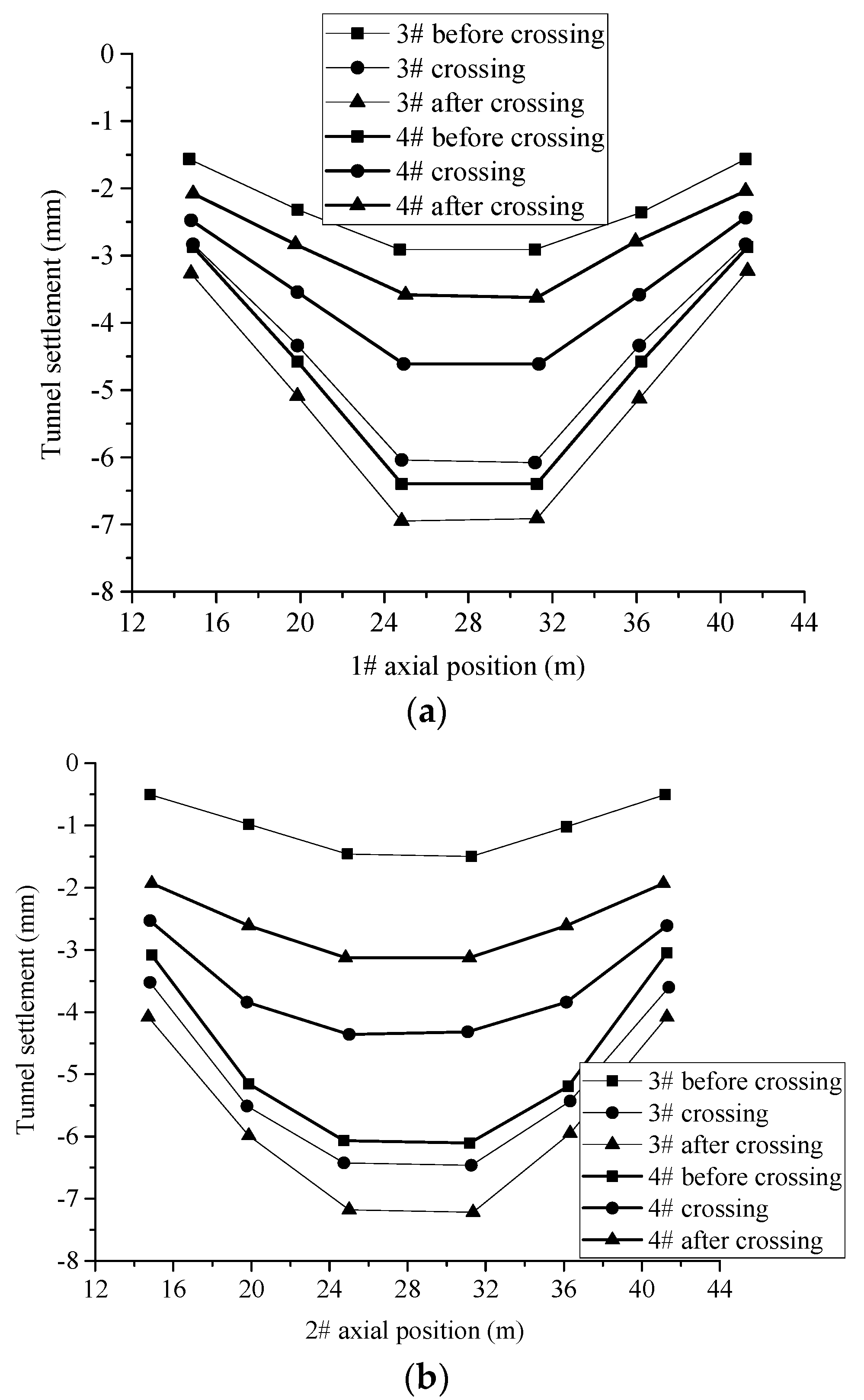
3.2. Analysis of Tunnel Deformation
4. Conclusions
Author Contributions
Funding
Acknowledgments
Conflicts of Interest
References
- Zhao, W.; Jia, P.; Zhu, L.; Cheng, C.; Han, J.; Chen, Y.; Wang, Z. Analysis of the additional stress and ground settlement induced by the construction of double-O-tube shield tunnels in sandy soils. Appl. Sci. 2019, 9, 1399. [Google Scholar] [CrossRef] [Green Version]
- Han, J.-Y.; Zhao, W.; Jia, P.-J.; Guan, Y.-P.; Chen, Y.; Jiang, B.-F. Risk analysis of the opening of shield-tunnel circumferential joints induced by adjacent deep excavation. J. Perform. Constr. Facil. 2018, 32, 04017123. [Google Scholar] [CrossRef]
- Jin, D.; Yuan, D.; Li, X.; Zheng, H. Analysis of the settlement of an existing tunnel induced by shield tunneling underneath. Tunn. Undergr. Space Technol. 2018, 81, 209–220. [Google Scholar] [CrossRef]
- Chakeri, H.; Hasanpour, R.; Hindistan, M.A.; Ünver, B. Analysis of interaction between tunnels in soft ground by 3D numerical modeling. Bull. Eng. Geol. Environ. 2011, 70, 439–448. [Google Scholar] [CrossRef]
- Kong, X.X.; Xia, C.C.; Qiu, Y.L.; Zhang, L.Y.; Gong, J.W. Study of construction mechanical behavior of parallel-small spacing metro tunnels excavated by shield method and cross diaphragm (CRD) method in loess region. Rock Soil Mech. 2011, 32, 516–524. [Google Scholar]
- Liu, D.; Zuo, C.; Tang, X.; Ding, S.; Chen, J. Mechanical effects of adjacent metro shield construction of the first hole on the second hole. J. Cent. South Univ. (Sci. Technol.) 2017, 48, 1027–1034. [Google Scholar] [CrossRef]
- Lin, X.-T.; Chen, R.-P.; Wu, H.-N.; Cheng, H. Deformation behaviors of existing tunnels caused by shield tunneling undercrossing with oblique angle. Tunn. Undergr. Space Technol. 2019, 89, 78–90. [Google Scholar] [CrossRef]
- Ding, Z.; Wu, Y.; Zhang, X.; Chen, K. Numerical analysis of impact of soft soil shield tunnel crossing existing subway at close range. J. Cent. South Univ. (Sci. Technol.) 2018, 49, 663–671. [Google Scholar]
- Jin, D.; Yuan, D.; Liu, S.; Li, X.; Luo, W. Performance of existing subway tunnels undercrossed by four closely spaced shield tunnels. J. Perform. Constr. Facil. 2019, 33, 04018099. [Google Scholar] [CrossRef]
- Xie, X.; Tang, G. Effects of curved shield tunnelling adjacent to existing power tunnel. Eur. J. Environ. Civ. Eng. 2018, 22 (Suppl. 1), s164–s178. [Google Scholar] [CrossRef]
- Yuan, S. Analysis of influence of loess tunnel excavation in plateau area on stability of existing adjacent tunnel. Tunn. Constr. 2017, 37, 60–66. [Google Scholar]
- Ma, W.; Peng, H.; Yang, C. Construction parameters control of shield tunnel underneath traversing existing dual shield tunnels. J. Southwest Jiaotong Univ. 2018, 53, 119–127. [Google Scholar]
- Meng, Q. Study on the deformation and control of foundation in shield construction of four-line overlapped tunnel. Chin. J. Undergr. Space Eng. 2019, 15, 911–919, 926. [Google Scholar]
- Liu, W.; Wu, Y.; Zhao, H.; Xu, X.; Miao, L. Deformations of Subway Tunnels Induced by the Overcrossing Jacked Box Tunnels. Symmetry 2021, 13, 1800. [Google Scholar] [CrossRef]
- Zhang, M.; Zhang, J.; Wu, Y.; Jia, W.; Han, J.; Zhou, L. Analysis of the impact of a double-lane shield going up through a nearby metro tunnel in a fully weathered rock formation. China Civ. Eng. J. 2019, 52, 100–108. [Google Scholar]
- Geng, D.; Dai, N.; Guo, P.; Zhou, S.; Di, H. Implicit numerical integration of highly nonlinear plasticity models. Comput. Geotech. 2021, 132, 103961. [Google Scholar] [CrossRef]
- Geng, D.; Guo, P.; Zhou, S. Implicit numerical integration of an elasto-plastic constitutive model for structured clays. Chin. J. Theor. Appl. Mech. 2018, 50, 78–86. [Google Scholar]
- Zhang, D.M.; Huang, Z.K.; Li, Z.L.; Zong, X.; Zhang, D.M. Analytical solution for the response of an existing tunnel to a new tunnel excavation underneath. Comput. Geotech. 2019, 108, 197–211. [Google Scholar] [CrossRef]
- Tao, L.; Sun, B.; Li, X. Interaction analysis of double holes extremely close approaching parallel shield tunnel construction. Chin. J. Rock Mech. Eng. 2009, 28, 1856–1862. [Google Scholar]
- Cai, W.; Zhang, M.; Wu, H. Analysis of deformation of existing tunnel overlapped by new shield tunnel. J. Shanghai Univ. (Nat. Sci. Ed.) 2016, 22, 813–820. [Google Scholar]
- Choi, J.I.; Lee, S.W. Influence of existing tunnel on mechanical behavior of new tunnel. KSCE J. Civ. Eng. 2010, 14, 773–783. [Google Scholar] [CrossRef]
- Yang, J.; Liu, C.; Chen, Q.; Xie, X. Performance of overlapped shield tunneling through an integrated physical model tests, numerical simulations and real-time field monitoring. Undergr. Space 2017, 2, 45–59. [Google Scholar] [CrossRef]
- Zhang, X.; Zhang, M.; Li, L. Study on construction disturbance mechanism of multi-lane stacked shield tunnel close crossing. Rock Soil Mech. 2017, 38, 1133–1140. [Google Scholar]
- Zhang, J.; Ye, L.; Yan, C.; Yan, B.; Wei, P.; Feng, J. Study on construction influence of shield tunnel of urban rail transit on large-section mining tunnel. Adv. Civ. Eng. 2020, 2020, 6836492. [Google Scholar] [CrossRef]
- Xiaoqing, Z.; Meng, Z.; Yingming, W.; Lei, L.; Youcheng, W. Model test on approaching construction of multi-line overlapped shield tunnelling. J. Shanghai Jiaotong Univ. 2015, 49, 1040–1045. [Google Scholar]
- Sun, J.; Xiao, W. Design on model test of shield tunnel in transparent soil. J. Wuhan Univ. Technol. 2011, 33, 108–112. [Google Scholar]


| Outer Diameter (mm) | Segment Thickness (mm) | Width of Segment Ring (mm) | Elastic Modulus (MPa) | |
|---|---|---|---|---|
| Prototype tunnel | 6400 | 350 | 1200 | 32,500 |
| Model tunnel | 160 | 9.5 | 300 | 820 |
| Crossing Mode | Cumulative Settlement (mm) | Maximum Change in Single Settlement (mm) |
|---|---|---|
| First-up and then-down crossing | 20.10 | 6.20 |
| First-down and then-up crossing | 19.10 | 7.70 |
| Crossing Method | Cumulative Settlement (mm) | Maximum Change in Single Settlement (mm) | ||
|---|---|---|---|---|
| No. 1 | No. 2 | No. 1 | No. 2 | |
| First-up and then-down crossing | 2.2 | 1.8 | 3.6 | 3.6 |
| First-down and then-up crossing | 3.2 | 4.7 | 3.7 | 3.1 |
Publisher’s Note: MDPI stays neutral with regard to jurisdictional claims in published maps and institutional affiliations. |
© 2022 by the authors. Licensee MDPI, Basel, Switzerland. This article is an open access article distributed under the terms and conditions of the Creative Commons Attribution (CC BY) license (https://creativecommons.org/licenses/by/4.0/).
Share and Cite
Liu, S.; Wang, Y.; Zhou, H.; Sun, C.; Lin, D. Model Test on Approaching the Construction of Multi-Line Overlapping Shield Tunnels for Up- and Down-Crossing. Processes 2022, 10, 500. https://doi.org/10.3390/pr10030500
Liu S, Wang Y, Zhou H, Sun C, Lin D. Model Test on Approaching the Construction of Multi-Line Overlapping Shield Tunnels for Up- and Down-Crossing. Processes. 2022; 10(3):500. https://doi.org/10.3390/pr10030500
Chicago/Turabian StyleLiu, Shangge, Yuanhai Wang, Hui Zhou, Changzhong Sun, and Dongfei Lin. 2022. "Model Test on Approaching the Construction of Multi-Line Overlapping Shield Tunnels for Up- and Down-Crossing" Processes 10, no. 3: 500. https://doi.org/10.3390/pr10030500
APA StyleLiu, S., Wang, Y., Zhou, H., Sun, C., & Lin, D. (2022). Model Test on Approaching the Construction of Multi-Line Overlapping Shield Tunnels for Up- and Down-Crossing. Processes, 10(3), 500. https://doi.org/10.3390/pr10030500