Article

Detailed Analysis of Exergy Destruction of All Basic Types of Heat Exchangers

Faculty of Mechanical Engineering and Naval Architecture, University of Zagreb, Ivana Lučića 5, HR-10000 Zagreb, Croatia
*
Author to whom correspondence should be addressed.
Processes 2022, 10(2), 249; https://doi.org/10.3390/pr10020249
Submission received: 30 November 2021 / Revised: 18 January 2022 / Accepted: 24 January 2022 / Published: 27 January 2022

Abstract

:
Dimensionless expressions of exergy destruction, normalized to ambient temperature and heat capacity of the weaker stream, for all basic types of recuperators are derived. The analytical expressions for maximum exergy destruction were calculated using the GNU Octave software for all recuperators, namely parallel-flow and counter-flow recuperators, and all forms of cross-flow heat exchangers, namely without mixing of streams, only mixing the streamlines of the weaker stream, only mixing the streamlines of the stronger stream and mixing the weaker and stronger streams. For parallel-flow and counter-flow recuperators, as well as for their special cases, expressions for local and total exergy destruction are given. It is shown that the maximum exergy destruction, as a local extreme, is the same for all recuperators for mutually equal values of the quantities π3 (ratio of the heat capacity of the weaker stream to the heat capacity of the stronger stream) and πT (ratio of the inlet temperature of the stronger stream to the inlet temperature of the weaker stream). The ratio of exergy destruction to effectiveness of each basic type of recuperator is further analyzed. The obtained results are presented and interpreted in appropriate dimensionless diagrams.

1. Introduction

Back in 1938, Professor Bošnjaković wrote the pioneering paper “Kampf den Nichtumkehrbarkeiten” [1], which states the fact that in all thermal problems it is necessary to detect causes of irreversibility and to reduce them if possible. Shortly afterward, Professor Rant introduces the notion of exergy which is also directly related to irreversibilities in the observed process [2]. Each process, according to the second law of thermodynamics, generates a positive increase in entropy which when multiplied by the thermodynamic ambient temperature, according to the Gouy–Stodola theorem [3,4], denotes exergy destruction. Many scientific books, as well as many scientific papers, have been written in which numerous thermal problems are analyzed from the aspect of entropy or exergy. The concepts of irreversibility, entropy generation and exergy destruction are well known and were described decades ago by Bejan [5].
To evaluate the performance of heat exchange, some researchers presented reviews of second-law-based analysis [6,7] with classified performance criteria (entropy and exergy as evaluation parameters). Estimation of thermodynamic efficiency is based on an assessment of energy that is available to be used (exergy), or analogously irreversibility (entropy) generation. It can be seen from literature review how entropy generation minimization and exergy destruction are powerful tools in the optimization of thermodynamic systems. Many researchers have investigated this important topic, using experimental or numerical methods in different types of heat exchangers and different fluids inside them. Heat transfer and entropy generation are numerically investigated in shell and helically coiled finned tube heat exchangers and presented in the study of Sepehr et al. [8]. According to the results, correlation is suggested for the calculation of entropy generation rate based on the values of the operational and geometrical variables. Genić et al. [9] developed a methodology of entropy generation minimization for counter-current and cocurrent heat exchangers which can be applied in the general case for all types of heat exchangers. The methodology is based on combining the second law of thermodynamics with the number of transfer units (NTU) method. In order to investigate the entropy transportation process inside a plate and tube heat exchanger, Guzmán et al. [10] conducted numerical simulations in their work. The authors analyzed and compared entropy levels around tubes with circular and elliptical cross-sections. The purpose of the comparison was to determine how the entropy flux contributes to the value of the entropy in certain regions of the flow field. An experimental study was conducted by Goh et al. [11] with the aim to determine the effects of interturbulator distance of rotating turbulator inserts on the heat transfer enhancement and entropy generation of forced convection in the turbulent flow region of a heat exchanger. Etghani and Baboli [12] developed a numerical model of a shell and helical tube heat exchanger and examined the effect of geometry and design parameters on heat transfer and exergy loss. The Taguchi method was used to obtain the optimum values of the design variables. According to the research, it has been proven that tube diameter and cold flow rate are the most significant design parameters of heat transfer and exergy loss. In their study, Wang et al. [13] established a numerical method for analyzing the effect of fin geometry and the inlet mass flow rate on the exergy loss in cylindrical shell and the helically coiled finned tube heat exchangers with an internal core inside the shell. The study showed that exergy loss increases with the increase in the inlet mass flow rate of the shell side, height and number of fins, NTU, heat transfer and operation of the fan. Alimoradi [14] in his study presents exergy analysis for forced convection heat transfer in shell and helically coiled tube heat exchangers. The effect of operational and geometrical parameters on the exergy efficiency was obtained. Results of the study show that efficiency decreases linearly with the increase in the fluid’s dimensionless inlet temperature difference. Al-Salem et al. [15] used a numerical method to obtain correlations for estimation of the annulus section exergy efficiency and coefficient of exergy performance for steady-state heat transfer and fluid flow in the annulus section of a tube-in-tube conically coiled heat exchanger. The study showed that the highest values of the turn number and the minimum values of the Reynolds number, Prandtl number, tube diameter ratio and the cone angle in the studied range maximize the exergy efficiency and coefficient of exergy performance. Wilhelmsen et al. [16] evaluated the strategies to reduce exergy destruction and entropy production in the plate–fin heat exchangers in the cryogenic part of a hydrogen liquefaction facility. Two main sources of exergy loss are thermal gradients and ortho–para hydrogen conversion. The proposed solution for reducing exergy destruction is a combination of an improved catalyst and the use of hydrogen and helium–neon as refrigerants. Abu-Hamdeh et al. [17] used a numerical method to simulate the three-dimensional turbulent thermal energy transfer and fluid flow through a finned tube heat exchanger. Energy and exergy analyses were performed and a multiobjective model was defined to obtain the optimal and critical values of the operational and geometrical parameters. Equations for estimation of thermal effectiveness, dimensionless exergy loss and dimensionless work were suggested. The heat exchanger for air dehumidification using liquid desiccant is mainly composed of an air–solution heat exchanger (dehumidifier) and a solution–refrigerant heat exchanger, wherein there are three fluids, i.e., air, desiccant solution, and refrigerant. It was found that the largest exergy destructions took place in the regenerator and dehumidifier. Findings of research of Guan et al. [18] can be used for achieving an efficient air dehumidification process in a heat exchanger using liquid desiccant. Recent work from Xie et al. [19] fills the gap of heat transfer and the geometrical optimization study of helical microfin tubes. Based on the exergy destruction minimization principle, the geometrical parameters are optimized by using numerical methods.
Many researchers have examined the attributes of conventional fluids inside heat exchangers. The ordinary working fluids possess great thermal resistance owing to their poor thermal conductivity and therefore can negatively influence the overall efficiency of heat exchangers. To address this shortcoming, nanofluids (which comprise the suspension of nanoscaled metallic or nonmetallic particles inside a pure liquid) are used as advanced heat transfer fluids [20,21], but also many second-law-based analyses have been performed with them [22,23].
The idea behind this paper is to develop a dimensionless mathematical model for the calculation of exergy destruction for all basic types of heat exchangers using dimensionless quantities commonly used in effectiveness–NTU energy calculations. This means that in the scope of this paper, the influence of these quantities on exergy destruction in heat exchangers, which is a consequence only of heat transfer at final temperature differences between the streams, is analyzed in detail. However, total exergy destruction of a heat exchanger is a summarized consequence of the local contributions, so within this paper, a local and then global approach is used to obtain the solution of exergy destruction. The analytical expressions for maximum exergy destruction were calculated using the GNU Octave software (Version 3.4.3, John W. Eaton, Madison, WI, USA). The basic types of heat exchangers discussed in this paper are those for which every stream, weaker and stronger, passes over the heat exchanging area only once. Division is based on mutual stream direction: parallel-flow heat exchanger, counter-flow heat exchanger, cross-flow heat exchanger without mixing of streamlines, cross-flow heat exchanger with mixing of only weaker stream streamlines, cross-flow heat exchanger with mixing of only stronger stream streamlines and cross-flow heat exchanger with mixing of weaker and stronger stream streamlines.

2. Mathematical Model

Model development for calculation of dimensionless exergy destruction uses the same presumptions as in development of existing models for function dependence ε = π1 = f(π2 = NTU; π3) [24], which means a constant value of the heat transfer coefficient and heat capacity of weaker and stronger streams. For calculating the mentioned values, the physical properties of streams are taken as arithmetic means of the inlet and outlet temperatures of each stream. The model neglects the effect of the environment on the amount of heat flow rate, which means that the heat exchanger is observed as an adiabatic system. The model for the calculation of the ratio of exergy destruction to effectiveness is obtained using the same presumptions, so those results are also connected to the operating point of the heat exchanger.
In this work, exergy destruction is a result of irreversible heat transfer between streams. Besides heat transfer, the exergy destruction in general depends also on stream pressure drop in a heat exchanger. However, as the primary goal of this paper is to connect the operating point of the heat exchanger given by the function ε =π1 = f(π2 = NTU; π3) with the corresponding dimensionless exergy destruction as well as the ratio of exergy destruction to effectiveness of each basic type of recuperator, the impact of the stream pressure drop is neglected.

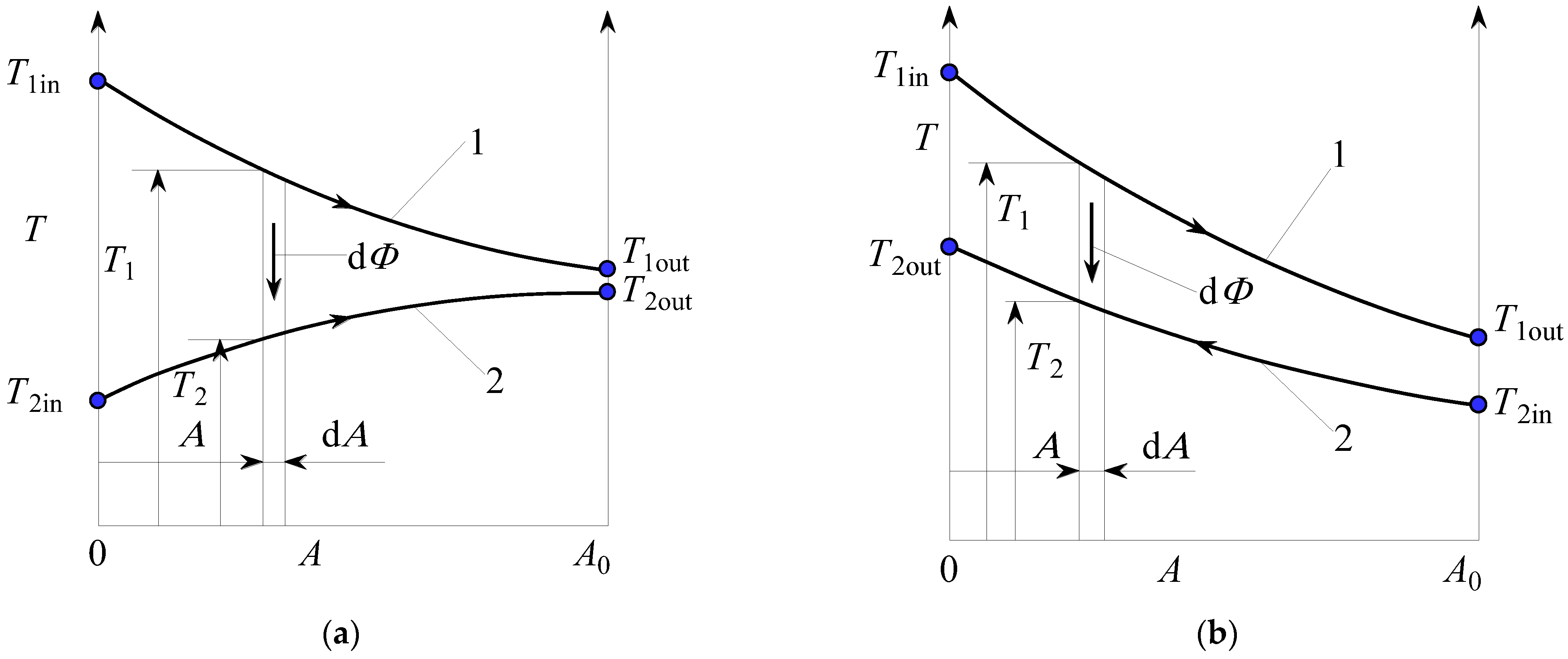
2.1. Local and Total Exergy Destruction of Parallel-Flow and Counter-Flow Recuperators

Since the total exergy destruction on the finite-surface recuperator is a consequence of the summarized local effects, the differential amount of exergy destruction for the observed recuperators is shown in Figure 1a,b.
The differential amount of heat transfer rate is [24]
d Φ = U ( T 1 T 2 ) d A
The corresponding differential entropy increment is given with the following equation [5]:
d S is . syst = d Φ T 1 + d Φ T 2 = U ( T 1 T 2 ) 2 T 1 T 2 d A
The total entropy generated due to irreversible heat transfer is
Δ S is . syst = U A = 0 A ( T 1 T 2 ) 2 T 1 T 2 d A
The following dimensionless quantities are also used for further analysis [24,25]:
π 3 = m ˙ 1 c p 1 m ˙ 2 c p 2 = C ˙ 1 C ˙ 2
π T = T 2 in T 1 in
π 2 = N T U = U A 0 / C ˙ 1
π 1 = ε = T 1 in T 1 out T 1 in T 2 in

2.1.1. Parallel-Flow Recuperator

By placing a system of energy differential equations on a parallel-flow recuperator, the following expressions for local values of temperatures of weaker and stronger streams are determined [25]:
T 1 = B 1 + B 2 exp ( ( 1 + π 3 ) A A 0 )
T 2 = B 1 π 3 B 2 exp ( ( 1 + π 3 ) A A 0 )
where the constants are determined from the boundary condition that for A = 0, T1 = T1in and T2 = T2out.
B 1 = T 2 in + π 3 T 1 in 1 + π 3 , B 2 = T 1 in T 2 in 1 + π 3
By including Equations (8) and (9) together with Equation (10) in Equation (3), and using the Gouy–Stodola theorem [3,4], and after integration, the following expression for local exergy destruction in a parallel recuperator is obtained:
( Δ E x ( A / A 0 ) C 1 T ok ) p a r = ln π T + π 3 + ( 1 π T ) exp ( π 2 ( 1 + π 3 ) A A 0 ) 1 + π 3 + 1 π 3 ln π T + π 3 π 3 ( 1 π T ) exp ( π 2 ( 1 + π 3 ) A A 0 ) ( 1 + π 3 ) π T
where Tok is ambient temperature.
If A/A0 = 1.0 is included in the above equation, an expression that describes the total (global) exergy destruction of the parallel-flow recuperator is obtained:
( Δ E x C 1 T ok ) p a r = ln π T + π 3 + ( 1 π T ) exp ( π 2 ( 1 + π 3 ) ) 1 + π 3 + 1 π 3 ln π T + π 3 π 3 ( 1 π T ) exp ( π 2 ( 1 + π 3 ) ) ( 1 + π 3 ) π T
By searching for the extremum of Equation (12) with respect to the variable π2, according to the performed procedure, it is easily shown that the maximum exergy destruction is achieved for π2stac,par → ∞, so its inclusion in Equation (12) gives the expression for maximum exergy destruction of a parallel-flow recuperator.
( Δ E x C 1 T ok ) p a r , max = ln π T + π 3 1 + π 3 + 1 π 3 ln π T + π 3 ( 1 + π 3 ) π T

2.1.2. Counter-Flow Recuperator

For the counter-flow recuperator, expressions for the local temperature of both streams are [25]
T 1 = B 1 + B 2 exp ( π 3 ( π 3 1 ) A A 0 )
T 2 = B 1 + π 3 B 2 exp ( π 3 ( π 3 1 ) A A 0 )
The constants B1 and B2 follow from the boundary conditions A = 0, T1 = T1in, and A = A0, T2 = T2in.
B 1 = ( T 1 in T 2 in ) exp ( π 2 ( 1 π 3 ) ) exp ( π 2 ( 1 π 3 ) ) π 3 ; B 2 = T 2 in exp ( π 2 ( 1 π 3 ) ) π 3 T 1 in exp ( π 2 ( 1 π 3 ) ) π 3
By including Equations (14) and (15) together with Equation (16) in Equation (3) and by carrying out the integration, the term for local exergy destruction of the counter-flow recuperator is obtained:
( Δ E x ( A / A 0 ) C 1 T ok ) c o = ln π T π 3 exp ( π 2 ( 1 π 3 ) ) + ( 1 π T ) exp ( π 2 ( 1 π 3 ) A A 0 ) 1 π 3 exp ( π 2 ( 1 π 3 ) ) + 1 π 3 ln π T π 3 exp ( π 2 ( 1 π 3 ) ) + ( 1 π T ) π 3 π T π 3 exp ( π 2 ( 1 π 3 ) ) + ( 1 π T ) π 3 exp ( π 2 ( 1 π 3 ) A A 0 )
The total (global) exergy destruction is obtained for A/A0 = 1.0.
( Δ E x C 1 T ok ) c o = ln π T π 3 exp ( π 2 ( 1 π 3 ) ) + ( 1 π T ) exp ( π 2 ( 1 π 3 ) ) 1 π 3 exp ( π 2 ( 1 π 3 ) ) + 1 π 3 ln π T π 3 exp ( π 2 ( 1 π 3 ) ) + ( 1 π T ) π 3 π T π 3 exp ( π 2 ( 1 π 3 ) ) + ( 1 π T ) π 3 exp ( π 2 ( 1 π 3 ) )
From Equations (17) and (18), a solution for a balanced counter-flow recuperator where π3 = 1.0 is obtained:
( Δ E x ( A / A 0 ) C 1 T ok ) c o , π 3 = 1.0 = ln π 2 ( 1 π T ) A A 0 + π 2 π T + π T π T ( π 2 + 1 ) + ln π 2 ( 1 π T ) A A 0 + π 2 π T + 1 π 2 π T + 1
when π2 → ∞, local and thus total exergy destruction → 0, which means that heat transfer between streams in a balanced counter-flow recuperator takes place with vanishing temperature differences; i.e., such a balanced counter-flow recuperator hypothetically works reversibly.
The total exergy destruction of the balanced counter-flow recuperator is shown with Equation (20):
( Δ E x C 1 T ok ) c o , π 3 = 1.0 = ln π 2 + π T π 2 π T + π T ln π 2 + 1 π 2 π T + 1
In order to check whether Equation (18) has an extremum with respect to variable π2, it is necessary to find a value (π2 = π2stac) [26]:
π 2 stac = 1 1 π 3 ln 1 π 3
Equation (21) shows that the value of π2stac depends only on π3, not on πT.
By including Equation (21) in Equation (18), the expression for maximum exergy destruction in a counter-flow recuperator is obtained.
( Δ E x C ˙ 1 T ok ) c o , max = ln π 3 + π T 1 + π 3 + 1 π 3 ln π 3 + π T π T ( 1 + π 3 )
By comparing Equations (13) and (22), it can be concluded that in both parallel-flow and counter-flow recuperators for the same πT and π3, the same values of maximum exergy destruction are achieved.
For a balanced counter-flow recuperator, the expression for π2stac is obtained directly by searching for the extremum of the function in Equation (20) or by applying L’Hopital’s rule to Equation (21).
π2stac(π3 = 1.0) = 1.0
Returning (23) to Equation (20) gives the expression for the maximum exergy destruction of the balanced counter-flow recuperator.
( Δ E x C ˙ 1 T ok ) c o ,   max ,   π 3 =   1 , 0   = ln ( 1 + π T ) 2 4 π T
The principal question is what physically represents, in terms of changes in stream temperatures, the value π2stac. In order to answer this question, it is good to start from the case of a balanced counter-flow recuperator for which π2stac = 1.0 follows from Equation (23), and then from Equation (37) it follows that
ε = π 2 stac π 2 stac + 1 = 1 2 = 0.50 .
From Equation (7) and the energy balance of the balanced counter-flow recuperator, temperature T1out equals
T 1 out = T 2 out = T 1 in + T 2 in 2
That is, the outlet temperatures of both streams in this case are equal to the arithmetic mean of the input stream temperatures, as qualitatively shown in Figure 2b.
For a case where π2A < π2B = 1.0, temperature distribution is shown qualitatively in Figure 2a, and for a case where π2C > π2B = 1.0, temperature distribution is shown in Figure 2c.
Completely analogous phenomena also occur in other counter-flow recuperators where π3 ≠ 1.0, shown in Figure 3a–c. For π2 = π2st, equal outlet stream temperatures are obtained. Such temperatures would be obtained if the inlet streams were mixed in one adiabatic mixing chamber. According to this fact, the energy equation of the adiabatic mixing chamber is given, with a condition: Tout = T1out = T2out.
C ˙ 1 T 1 in + C ˙ 2 T 2 in = ( C ˙ 1 + C ˙ 2 ) T out
T out = π 3 T 1 in + T 2 in 1 + π 3
Equation (27) refers to Figure 3b, which shows that the output temperatures of the weaker and stronger streams are equal. For this case, π2B = π2stac is determined by Equation (21). Case π2A < π2B is shown in Figure 3a, and case π2C > π2B is presented with Figure 3c.

2.1.3. Solutions for the Case π3 = 0.0

From the obtained solutions for the local and total exergy destruction for the parallel-flow and counter-flow recuperators, a solution is easily reached for a case when the stronger stream evaporates or condenses (π3 = 0.0).
( Δ E x ( A / A 0 ) C ˙ 1 T ok ) π 3 =   0 . 0   = ln ( π T + ( 1 π T ) exp ( π 2 A A 0 ) ) + 1 π T π T ( 1 exp ( π 2 A A 0 ) )
When A/A0 = 1.0, an expression for the total exergy destruction is obtained:
( Δ E x C ˙ 1 T ok ) π 3 = 0.0 = ln [ 1 ε ( 1 π T ) ] + ε 1 π T π T
Thus, the maximum of exergy destruction occurs in the counter-flow recuperator for the value of π2stac which is determined by Equation (21), while for the parallel recuperator as well as the recuperator with phase change, this maximum occurs for π2stac → ∞.

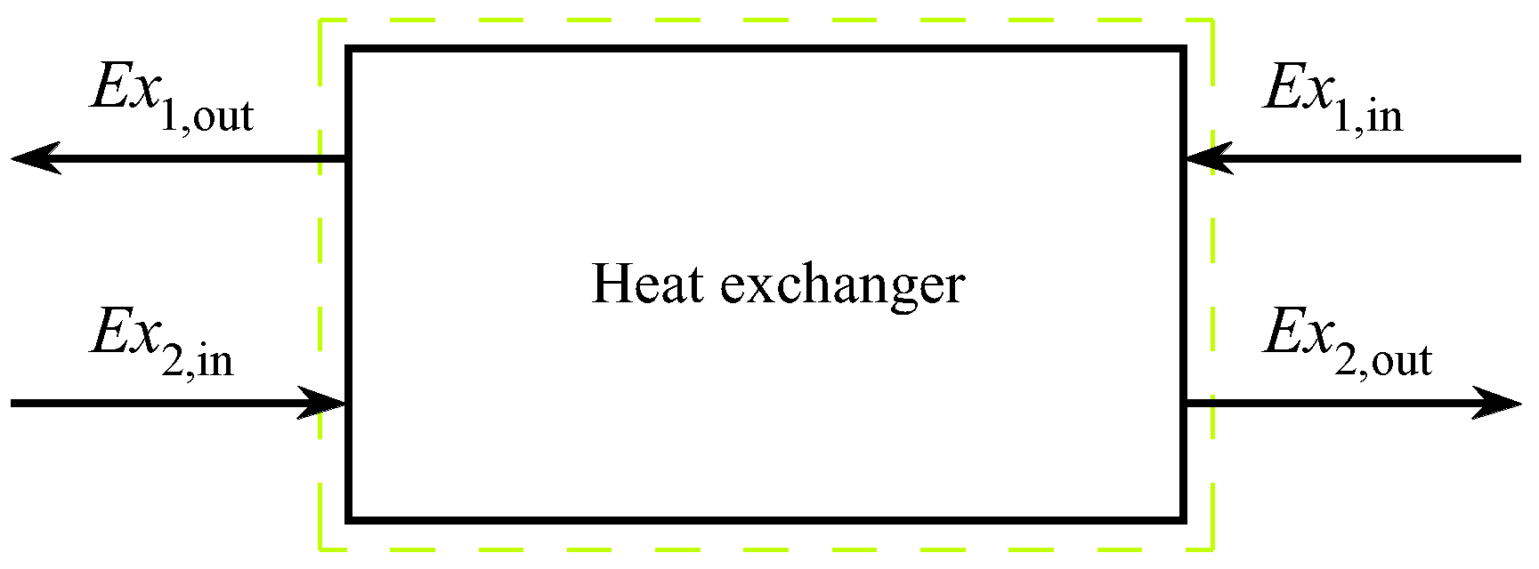
2.2. Total Exergy Destruction of All Basic Types of Heat Exchangers

The previous overall solutions are also reached by the so-called global approach to the problem. Such an approach will provide a solution also for all forms of cross-flow recuperators. From the temperature flow of stream along the heat exchanger surface of the cross-flow recuperator, it is intuitively inferred that the finite values of π2stac exist, for which maximum exergy destruction also occurs. In order to achieve this in general, the global exergy balance is set for the total heat exchanger area, shown in Figure 4.
Δ E x = E x 1 in E x 1 out + E x 2 in E x 2 out
The change in exergy of the weaker stream, index 1, and the change in exergy of the stronger stream, index 2, can be expressed as follows [27,28,29,30]:
E x 1 in E x 1 out = m ˙ 1 [ c p 1 ( T 1 in T 1 out ) T ok c p 1 ln T 1 in T 1 out ]
E x 2 in E x 2 out = m ˙ 2 [ c p 2 ( T 2 in T 2 out ) T ok c p 2 ln T 2 in T 2 out ]
By including Equations (31) and (32) in Equation (30), the expression for exergy destruction can be changed to the following dimensionless form:
Δ E x C ˙ 1 T ok = ln T 1 out T 1 in + 1 π 3 ln T 2 out T 2 in
By using Equations (4)–(7), it can be written in the following dimensionless form:
Δ E x C ˙ 1 T ok = ln [ 1 ε ( 1 π T ) ] + 1 π 3 ln [ 1 + π 3 ε 1 π T π T ]
In the case of evaporator or condenser, Equation (34) is transformed into the following form:
( Δ E x C ˙ 1 T ok ) π 3 = 0.0 = ln [ 1 ε ( 1 π T ) ] + ε 1 π T π T
For parallel-flow (par) and counter-flow (co) recuperators, the effectiveness ε is given by the following equations [5,27,28,29,30]:
ε p a r = 1 exp ( ( 1 + π 3 ) π 2 ) 1 + π 3
ε c o = 1 exp ( ( 1 π 3 ) π 2 ) 1 π 3 exp ( ( 1 π 3 ) π 2 )
For a counter-flow recuperator, for which π3 = 1.0, Equation (37) is transformed into
ε p ( π 3 = 1.0 ) = π 2 π 2 + 1
By including Equation (38) in Equation (34), the expression for exergy destruction of a balanced counter-flow recuperator is obtained:
( Δ E x C 1 T ok ) π 3 = 1.0 = ln π 2 + π T π 2 π T + π T ln π 2 + 1 π 2 π T + 1
This expression is identical to the expression in Equation (20). This means that Equation (34) is a significant equation that describes the total exergy destruction in all types of recuperators. In addition to the already shown parallel-flow and counter-flow recuperators, Equation (34) can also be applied to cross-flow recuperators.
In the case of a cross-flow recuperator, four cases should be distinguished:
  • Without mixing streamlines of weaker and stronger streams (cr);
  • Mixing streamlines only of a weaker stream (cr1);
  • Mixing streamlines only of a stronger stream (cr2);
  • Mixing streamlines of both streams (cr12).
Effectiveness ε for these types of cross-flow recuperators is expressed by the following equations [29]:
ε c r = π 1 c r = 1 exp [ π 2 0 . 22 π 3 ( exp ( π 3 π 2 0.78 ) 1 ) ]
ε c r 1 = π 1 c r 1 = 1 exp ( 1 exp ( π 2 π 3 ) π 3 )
ε c r 2 = π 1 c r 2 = 1 π 3 [ 1 exp ( π 3 ( 1 exp ( π 2 ) ) ) ]
ε c r 12 = π 1 c r 12 = 1 1 1 exp ( π 2 ) + π 3 1 exp ( π 2 π 3 ) 1 π 2
In the case of evaporator or condenser, from Equations (36), (37) and (40)–(43),
ε p a r = ε c o = ε c r = ε c r 1 = ε c r 2 = ε c r 12 =   1 exp ( π 2 )
which confirms the already known fact that in this case the effectiveness does not depend on the type of recuperator.
All equations for the effectiveness of the recuperator show that the value of the effectiveness of all recuperators equals zero for π2 = 0, while for the hypothetical case π2 → ∞ it depends on the type of recuperator and its effectiveness is shown with the following equations:
ε p a r ( π 2 ) = 1 π 3 + 1
ε c o ( π 2 )   =   ε c r ( π 2 ) =   1 . 0
ε c r 1 ( π 2 ) =   1 exp ( 1 π 3 )
ε c r 2 ( π 2 ) = 1 exp ( π 3 ) π 3
ε c r 12 ( π 2 ) = 1 1 + π 3
The local extreme of the function in Equation (34) is given by the following expressions:
d d ε ( Δ E x C ˙ 1 T ok ) = d d ε { ln [ 1 ε ( 1 π T ) ] + 1 π 3 ln [ 1 + π 3 ε 1 π T π T ] } = 0
ε stac = 1 1 + π 3
It is interesting to note that the value of the stationary effectiveness of the recuperator εstac does not depend on the temperature ratio πT and that it is the same for the same values of π3 for all types of recuperators.
By finding the second derivative of the function in Equation (34) and including the expression in Equation (51), it is obtained that
d 2 d ε 2 [ ( Δ E x C ˙ 1 T ok ) ] ( ε stac = 1 1 + π 3 ) = ( 1 π T ) 2 ( 1 + π 3 ) 2 ( π 3 + π T ) 2 ( π 3 1 )
As the expression in Equation (52) is always less than zero, this means that the function (34) at the stationary point εstac has a local extreme maximum, the value of which is obtained by including Equation (51) in Equation (34).
( Δ E x C ˙ 1 T ok ) max = ln π 3 + π T 1 + π 3 + 1 π 3 ln π 3 + π T π T ( 1 + π 3 )
If in Equation (33), with condition T2out = T1out = Tout, Equation (27) is included, then the following expression follows:
( Δ E x C ˙ 1 T ok ) = ln T out T 1 in + 1 π 3 ln T out T 2 in = ln π 3 T 1 in + T 2 in 1 + π 3 T 1 in + 1 π 3 ln π 3 T 1 in + T 2 in 1 + π 3 T 2 in = ln π 3 + π T 1 + π 3 + 1 π 3 ln π 3 + π T π T ( 1 + π 3 )
which is equal to expression in Equation (53).
Equation (53) is identical to Equations (13) and (22), so it shows that all basic types of recuperators have the same maximum exergy destruction with the same π3 and πT values, where values of output stream temperatures are the same. The respective value of the output temperature of both streams corresponds to the value of the output temperature that would be obtained by adiabatic mixing of the streams.
Equation (53) can be further modified to two cases of recuperators; the first is the case for which π3 = 0.0, and the second case refers to the counter-flow recuperator for which π3 = 1.0.
( Δ E x C ˙ 1 T ok ) max , π 3 =   0 . 0   = ln ( π T ) + 1 π T π T
The same form of the equation is obtained if the extreme of Equation (28) is required, from which it follows that εstac = 1.0. By including this value in Equation (28), the expression in Equation (55) is obtained.
For the case of a counter-flow recuperator with π3 = 1.0, the following expression is obtained:
( Δ E x C ˙ 1 T ok ) c o   max , π 3 =   1 . 0   = ln ( 1 + π T ) 2 4 π T
which is equal to the derived expression shown in Equation (24).
Equation (51) shows that εstac is the same for the given π3 for all types of recuperators. Since ε, according to Equations (36)–(38) and (40)–(44), also depends on the type of recuperator, this means that each type of recuperator will have its corresponding π2stac at which the maximum value of exergy destruction is achieved.
π 2 stac ,   p a r = π 2 stac , π 3 = 0.0  
π 2 stac ,   c o = 1 1 π 3 ln ( 1 π 3 )
π 2 stac ,   c o ( π 3 = 1.0 ) = 1.0
π 2 stac ,   c r 1 = 1 π 3 ln ( 1 1 π 3 ln 1 + π 3 π 3 )
π 2 stac ,   c r 2 =   ln ( π 3 π 3 ln ( 1 + π 3 ) )
It is not possible to find an explicit solution for a cross-flow recuperator without mixing streamlines of weaker and stronger streams (cr) or for a cross-flow recuperator in which weaker and stronger streams mix (cr12), due to the complexity of Equations (40) and (43), as can be seen from the following:
1 exp [ π 2 0 . 22 π 3 ( exp ( π 3 π 2 0.78 ) 1 ) ] = 1 1 + π 3
1 1 1 exp ( π 2 ) + π 3 1 exp ( π 2 π 3 ) 1 π 2 = 1 1 + π 3
The structure of Equations (62) and (63) shows that for the mentioned cases (cr and cr12), the value π2stac must be found by a numerical procedure.

2.3. The Ratio of Exergy Destruction to Recuperator Effectiveness

The ratio of exergy destruction to recuperator effectiveness is shown with the following equation
Δ E x C ˙ 1 T ok ε = ln [ 1 ε ( 1 π T ) ] ε + 1 π 3 ε ln [ 1 + π 3 ε 1 π T π T ]
For π3 = 0.0, the above equation is transformed into the form
( Δ E x C ˙ 1 T ok ε ) π 3 = 0.0 = ln [ 1 ε ( 1 π T ) ] ε + 1 π T π T
where the values of ε are in the interval 0.0 ≤ εε (π2 → ∞). The values of units ε (π2 → ∞) for individual types of recuperators are determined by Equations (45)–(49). For ε = 0.0, Equation (64) is transformed into the following expression:
( Δ E x C ˙ 1 T ok ε ) ( ε 0 ) = ( 1 π T ) 2 π T
By including the expression for πT in the above equation, according to Equation (5), the following expression is obtained:
( Δ E x C ˙ 1 T ok ε ) ( ε 0 ) = ( T 1 in T 2 in ) 2 T 1 in T 2 in
It can be concluded that when the heat exchanger area tends to zero, expression (67) represents the maximum ratio of exergy destruction to recuperator effectiveness.
It is possible to explicitly express the magnitude of π2 depending on ε and π3, so these functions are given for individual recuperators:
π 2 p a r = 1 1 + π 3 ln 1 [ 1 ε p a r ( 1 π 3 ) ]
π 2 c o = 1 1 π 3 ln 1 π 3 ε c o 1 ε c o
π 2 c o ( π 3 = 1.0 ) = ε c o 1 ε c o
π 2 c r 1 = 1 π 3 ln 1 1 + π 3 ln ( 1 ε c r 1 )
π 2 c r 2 = ln π 3 π 3 + ln ( 1 π 3 ε c r 2 )
π 2 , π 3 = 0.0 = ln 1 1 ε
For cross-flow recuperators (cr and cr12), due to the structure of Equations (39) and (42), it is not possible to explicitly express the value of π2.

3. Results and Discussion

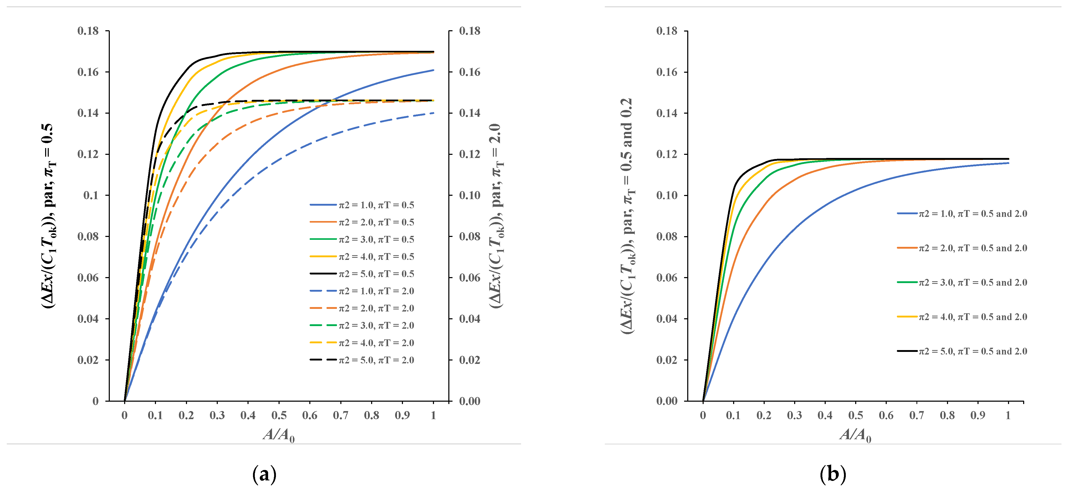
3.1. Presentation of Calculation Results for a Parallel-Flow Recuperator

Diagrams in Figure 5a,b show the local and the total exergy destruction of a parallel-flow heat exchanger for the selected values: πT = 0.50 and 2.0 and π3 = 1.0.
Figure 5a shows that in this case the local exergy destruction of the parallel recuperator increases continuously with the increase in the variable A/A0, as well as with the increase in the variable π2. It can also be seen from the same diagram that the values of exergy destruction are higher for πT = 0.50 (left ordinate axis, continuous lines) compared to πT = 2.0, which are shown on the right ordinate axis and with dashed lines. The values of total exergy destruction are read for individual π2 at the abscissa A/A0 = 1.0, and it can be seen that the values in question increase continuously with increasing π2. However, it can also be seen that for πT = 0.50 and πT = 2.0, there are asymptotic (maximum) values of exergy destruction, which are 0.1699 and 0.1462 and are easily proven by Equation (13). It can be concluded that in both cases the respective asymptotic values are practically reached for values π2 ≥ 2.0.
Figure 5b shows the local and total exergy destruction for π3 = 1.0 and πT = 0.50. These results are identical to results for π3 = 1.0 and πT = 2.0. In this case, the maximum value of exergy destruction is 0.1178, which is confirmed by the diagram in Figure 5b. In this case, the maximum (asymptotic) exergy destruction is practically achieved for π2 ≥ 2.0 too, so according to the irreversibility criterion, there is no justification for the operating point of a parallel recuperator when π2 ≥ 2.0.

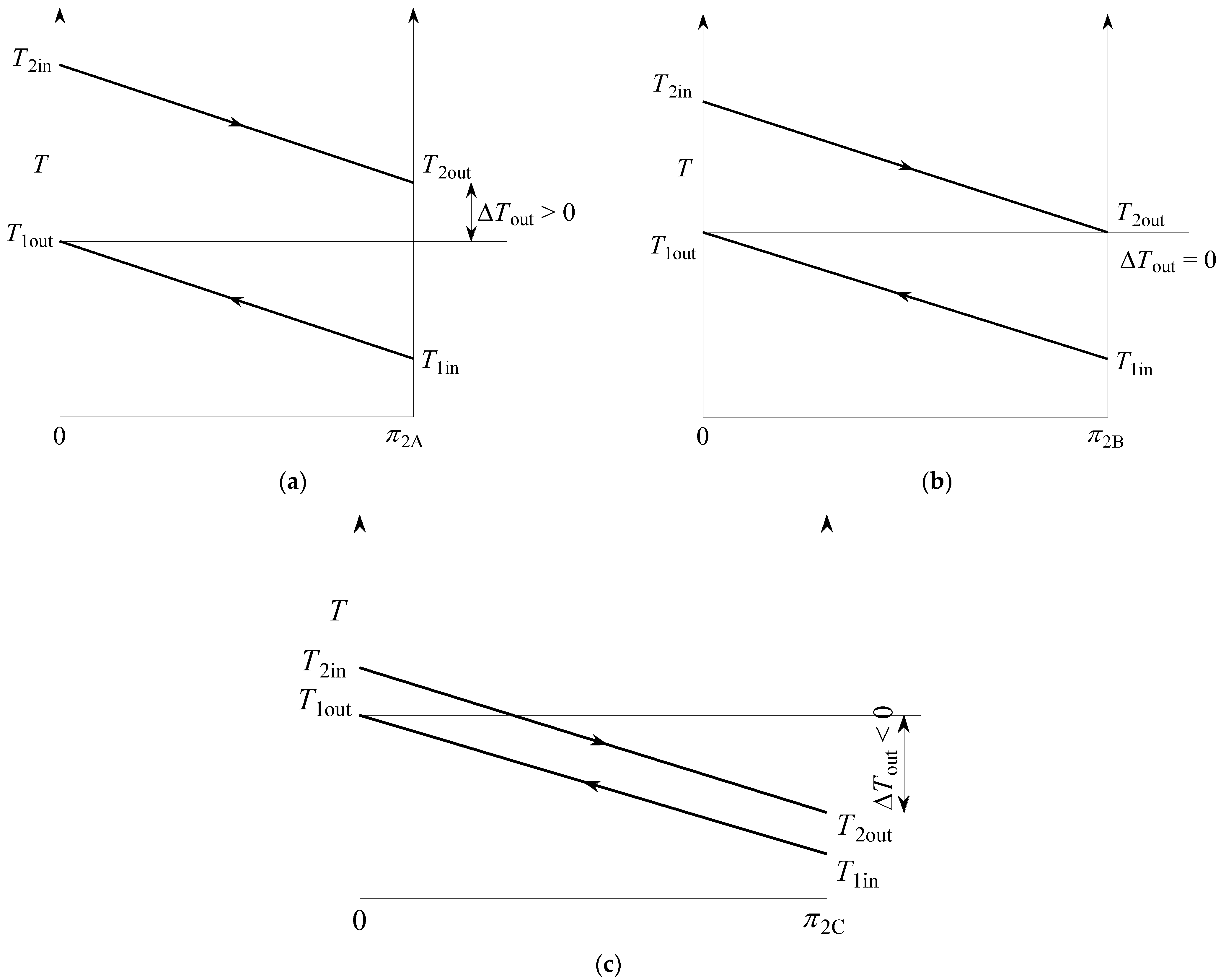
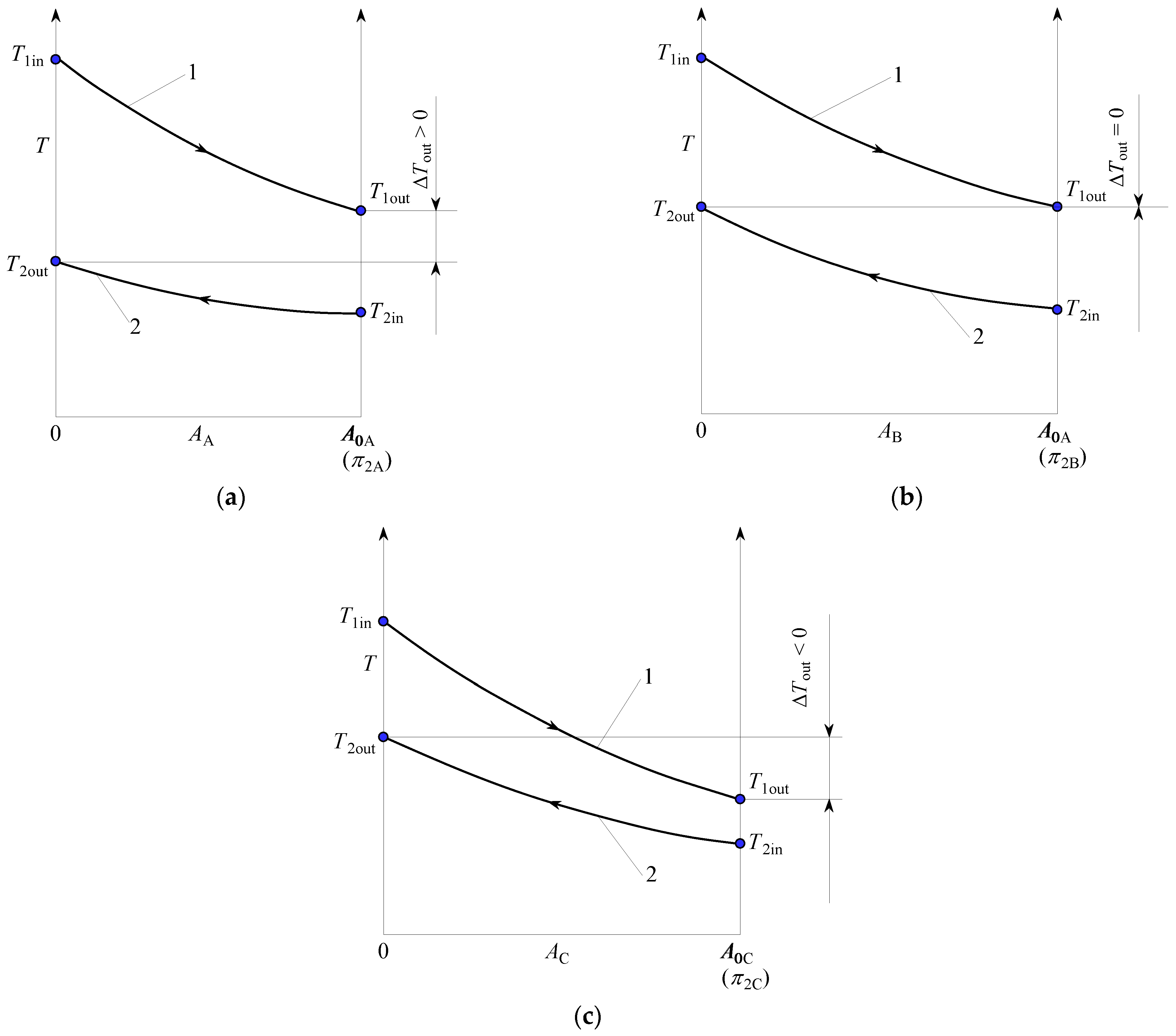
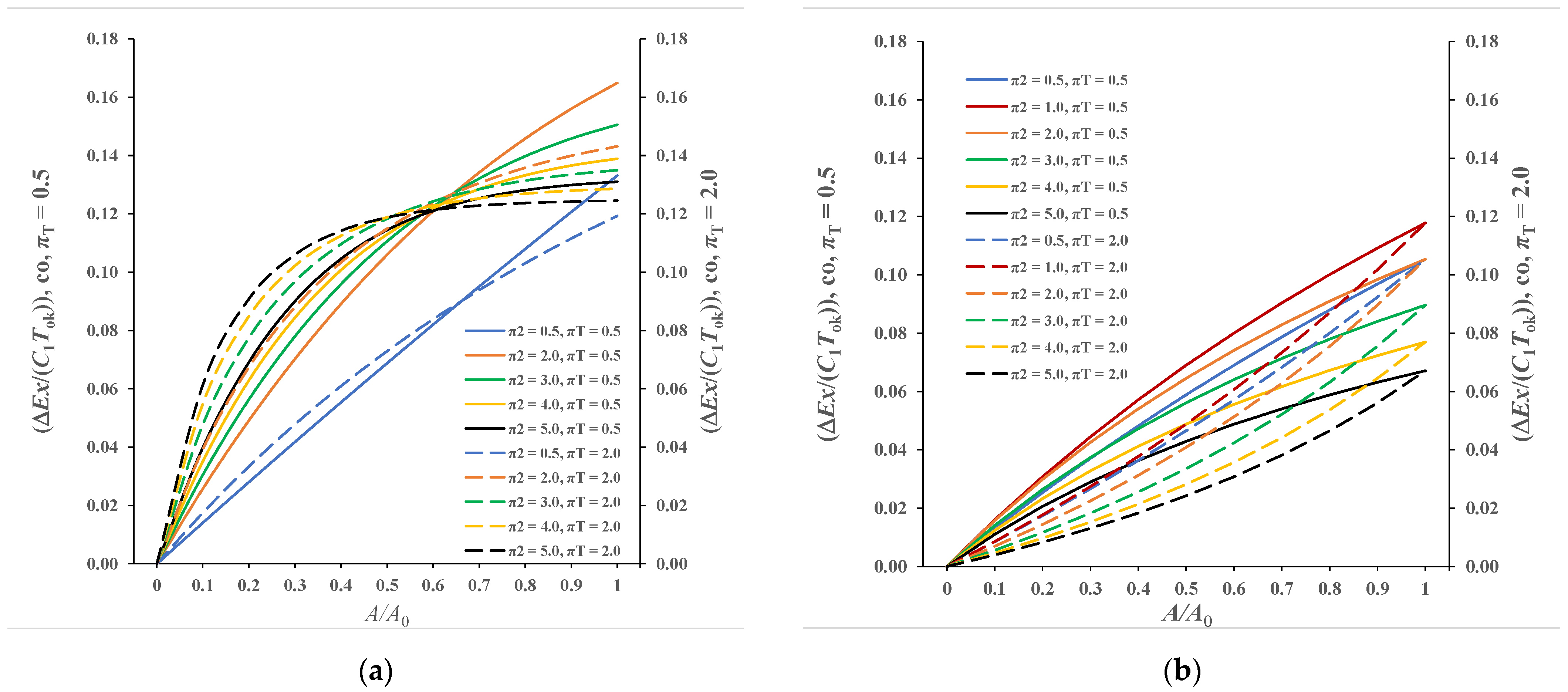
3.2. Presentation of Calculation Results for a Counter-Flow Recuperator

Diagrams in Figure 6a,b show the local and the total exergy destruction of the counter-flow recuperator for πT = 0.50 and 2.0 and π3 = 0.50 and 1.0.
From the diagram in Figure 6a,b, it can be seen that the local exergy destruction continuously increases from the value 0.0 to the final value of the recuperator, which is determined by the magnitude A/A0 = 1.0 with the corresponding π2. It can be seen from both diagrams that the final total amount of exergy destruction first increases with increasing π2, and then the value of exergy destruction decreases with a further increase in π2. This means (confirmed with Equations (21), (57) and (58)) that with the counter-flow recuperator there is a final value π2 = π2stac for which the maximum value of exergy destruction is achieved.

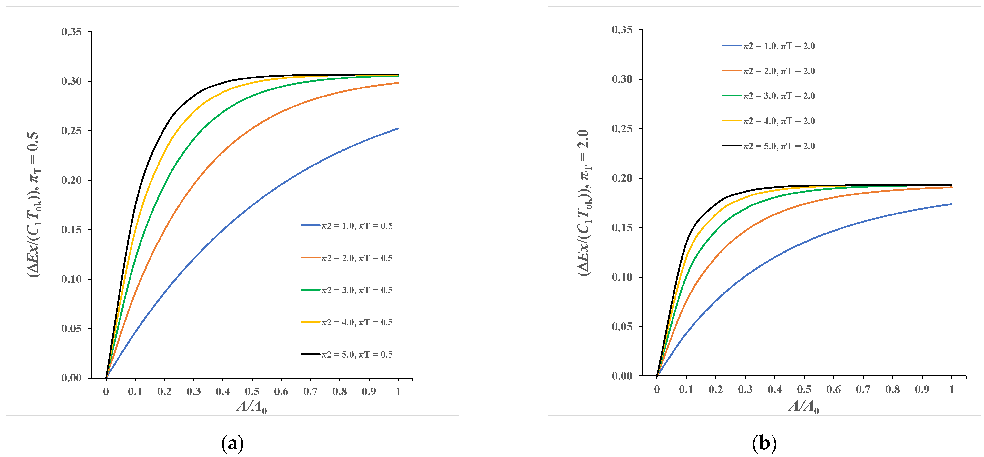
3.3. Presentation of Calculation Results for a Recuperator for Which π3 = 0.0

Diagrams in Figure 7a,b show the local and total exergy destruction for selected values πT = 0.50 and πT = 2.0 and indicated values of π2, for recuperators where a stronger stream condenses or evaporates. In this case, as shown in Equations (28), (29), (43) and (55), the type of recuperator is completely irrelevant.
The diagram in Figure 7a shows that the value of local exergy destruction continuously increases from zero to the values achieved for A/A0 = 1.0, with the corresponding π2. The respective values are shown for the selected π2 for the abscissa A/A0 = 1.0 and are as follows: 0.2522, 0.2894, 0.3056, 0.3067 and 0.3068. All curves tend to their asymptotic value determined by Equation (53), and this value for πT = 0.50 equals 0.30685. This means that these types of recuperators have practically already reached the maximum exergy destruction for π2 ≥ 3.0, and for these values the outlet temperature of the weaker stream, according to Equation (27), will practically achieve the value T1out = T2in = Tsat that represents the saturation temperature of a stronger stream.
The situation is completely similar in Figure 7b, which refers to πT = 2.0. Total values of exergy destruction at A/A0 = 1.0 are 0.1738, 0.1907, 0.1928, 0.1931 and 0.1931, while the maximum value of exergy destruction for this case is 0.19315. Maximum asymptotic values are explicitly confirmed by Equation (55).
This analysis, as confirmed by the diagrams above, shows that it makes no sense to increase the π2 value above 3.0, because such an unreasonable increase would lead to higher investment costs with a slight increase in recuperator effectiveness but with a significant (maximum) value of undesirable exergy destruction.

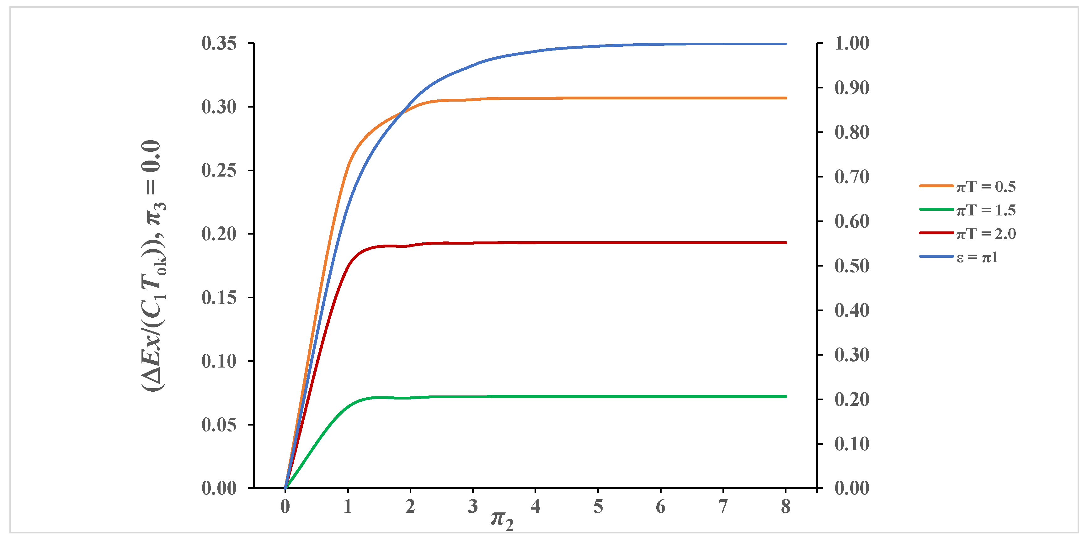
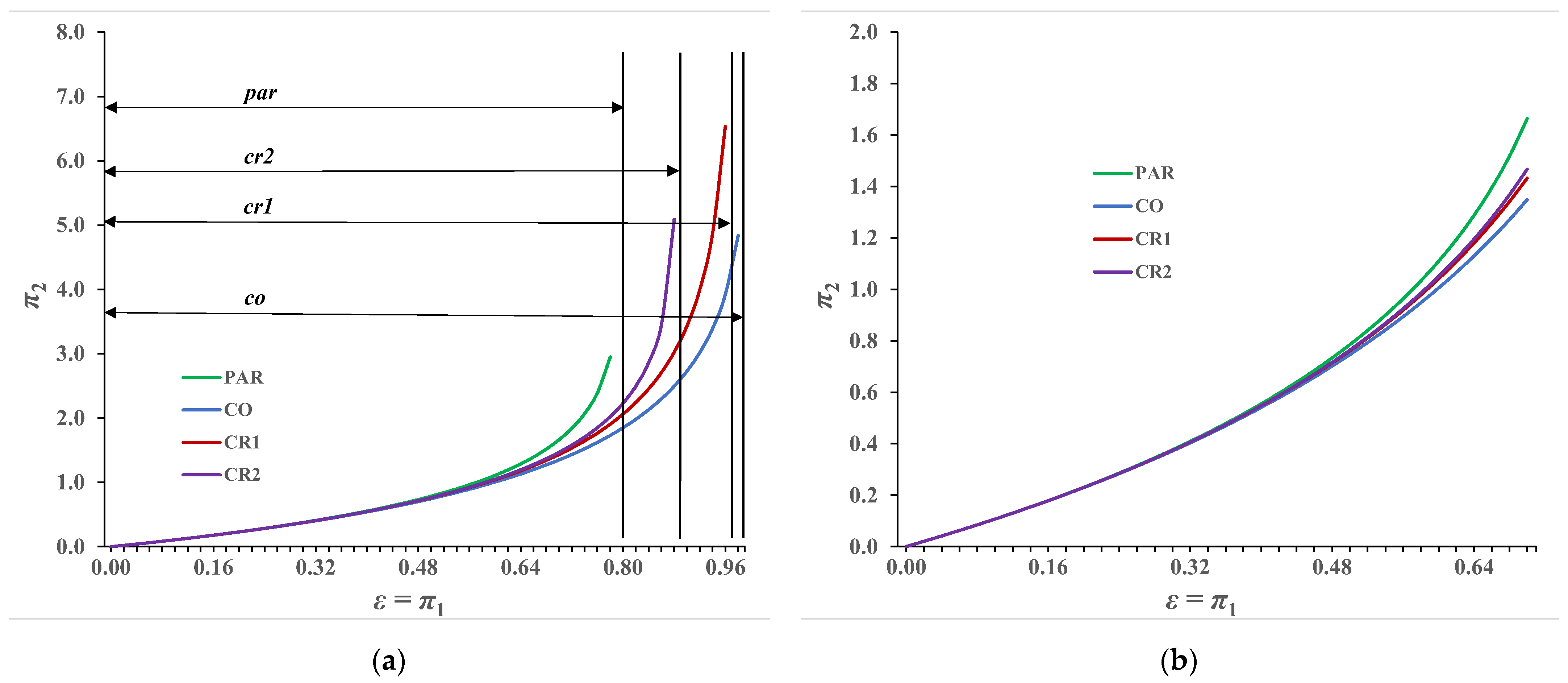
3.4. Presentation of Recuperator Calculation Results by Variable π2

The algorithm for calculating the total exergy destruction of all basic recuperators represented with Equations (30)–(63) shows that for a significant variable it is convenient to choose π2 so that the maximum exergy destructions for the values of π2stac can be visible in the diagrams. These values are determined with Equations (57)–(63).

3.4.1. Case π3 = 0.0

The diagram in Figure 8 shows the exergy destruction depending on π2 and πT in case the stronger stream changes its physical state. In the same diagram, the blue line shows the effectiveness of such a recuperator.
As already pointed out for this case, the type of recuperator has no effect on both the effectiveness and the amount of exergy destruction. The values of maximum exergy destruction are achieved relatively quickly; for πT = 0.50, 1.50 and 2.0, they are 0.3069, 0.0721 and 0.1931, respectively. It can be concluded that the working state of the recuperator with π2 > 3.0 makes no sense because for this area the increase in recuperator effectiveness is relatively small, while exergy destruction is practically maximum.

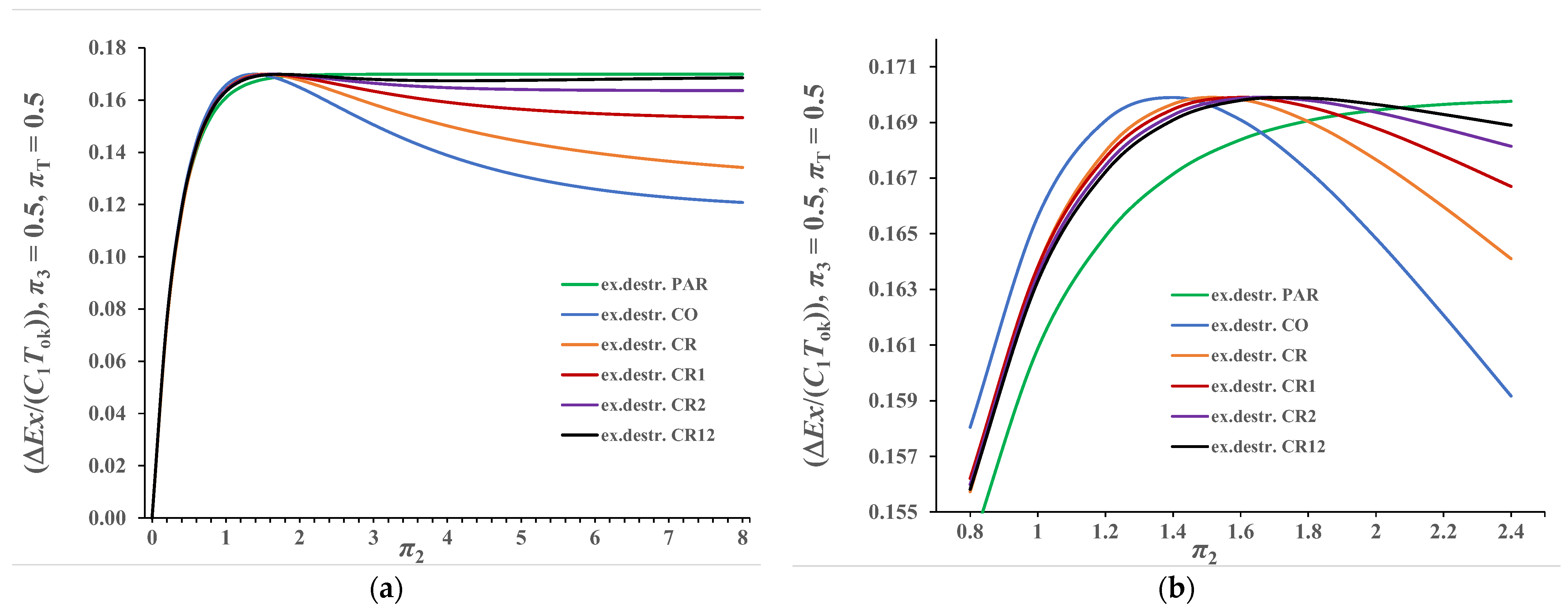
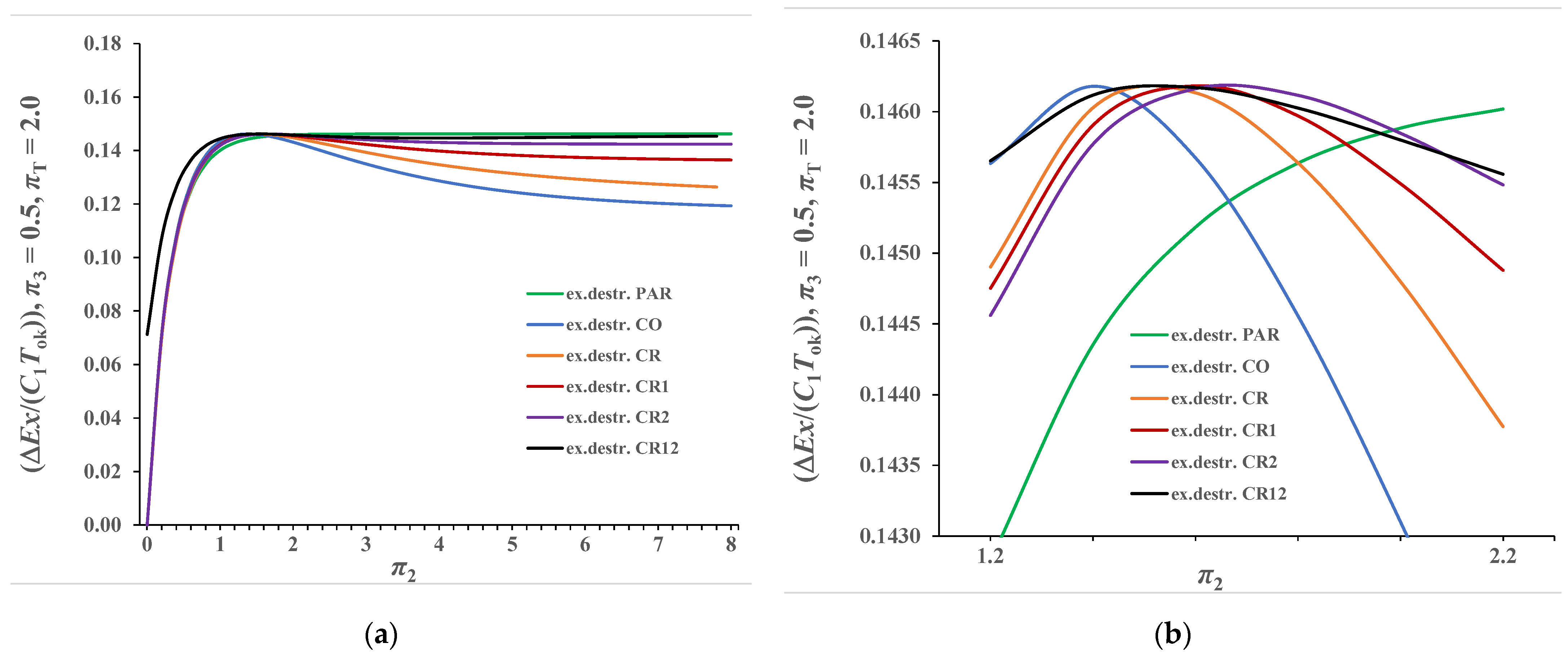
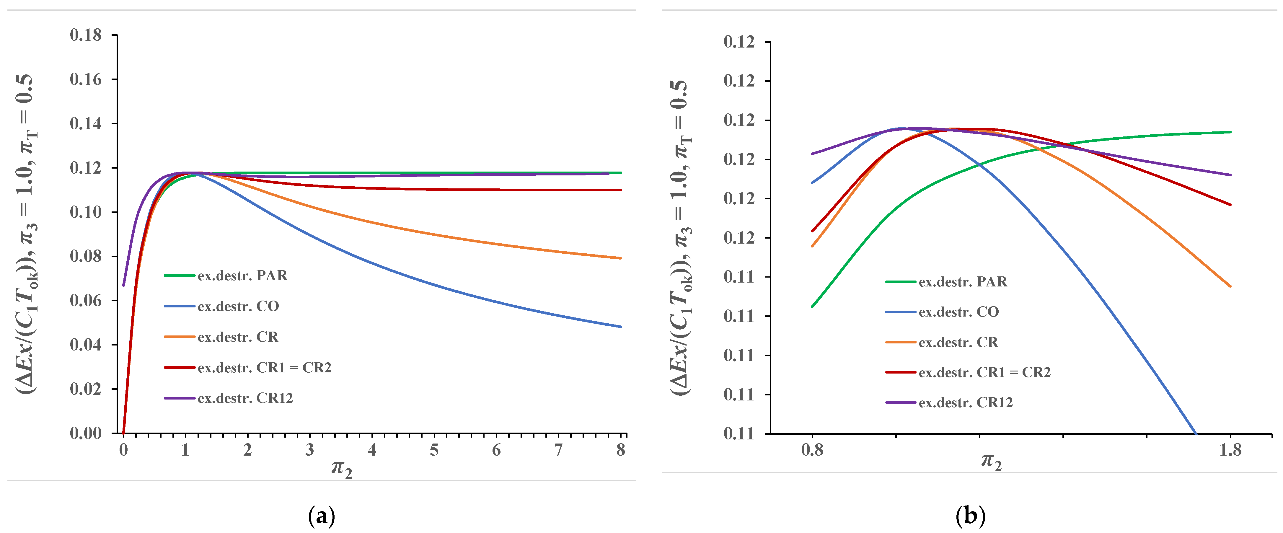
3.4.2. Case π3 ≠ 0.0

Each type of recuperator achieves different values of exergy destruction for π3 ≠ 0, so the diagram in Figure 9a,b shows the values of exergy destruction for all types of recuperators depending on π2, with selected values π3 = πT = 0.50.
The characteristic behavior of exergy destruction is such that it first increases, reaches a maximum and then decreases, except for the parallel-flow recuperator where exergy destruction increases continuously with the increase in π2. It is evident from the diagram, as shown in Equations (13), (22) and (53), that the achieved maxima, as local extremes, are the same for all types of recuperators and that maximum is 0.1699, which is at the same time the maximum exergy destruction of the parallel recuperator for π2 → ∞, which was practically reached for π2 = 2.60. When π3 equals 0.50, then εstac = 2/3 = 0.667 for all types of recuperators. Since the same values of πT are taken, according to Equation (53), the maximum values of exergy destruction must be equal. However, it can also be seen from the diagram in Figure 9a that the values of π2stac are not equal for the observed types of recuperators, which is clearly visible in Figure 9b.
These stationary values were determined with Equations (57), (58), (60) and (61) for parallel-flow recuperator, counter-flow recuperator, cross-flow recuperator with mixing streamlines of weaker stream and cross-flow recuperator with mixing streamlines of stronger stream. These values are ∞, 1.386, 1.594 and 1.666. Values π2stac,cr = 1.551 and π2stac,cr12 = 1.741 are determined by numerical procedure. It can be seen from Figure 9b that all cross-flow recuperators have mutually close values of exergy destruction for values π2 < π2stac, while more significant differences occur for π2 > π2stac.
Figure 10a,b represents results when π3 = 0.50 and πT = 2.0. The behavior of the curves is like that in the previous case, with the difference that in this case lower values of exergy destruction were obtained. The values π2stac in this observed case remained unchanged compared to the previous case because π3 also equals 0.50. Only the maximum value of exergy destruction decreased, which in this case, according to Equation (40), equals (∆Ex/(C1Tok))max = 0.1462.
The diagrams in Figure 11a,b show the values of exergy destruction of all recuperators as a function of π2 with πT = 0.50 and π3 = 1.0. The obtained values of exergy destruction, using Equations (20) and (39), are lower than the values shown in Figure 9a,b and Figure 10a,b. It is interesting to note here that the obtained values of exergy destruction are equal for a cross-flow recuperator with mixing streamlines only of a weaker stream and for a cross-flow recuperator with mixing streamlines only of a stronger stream.
In this case as well, each type of recuperator reaches a local extreme maximum, for which the positions of the corresponding π2stac, together with the equal values of the maxima, are more clearly shown in Figure 11b. In this case, according to Equation (51), εstac = 0.50, and the corresponding values of π2stac for counter-flow and all cross-flow recuperators are 1.0, 1.15, 1.18, 1.18 and 1.23. The maximum value of exergy destruction, according to Equation (56), is 0.1178.
It can be concluded that in the case of a parallel-flow recuperator and a recuperator with a phase change of a stronger stream, the maximum exergy destruction occurs when π2 → ∞ because only in these cases are temperatures of the streams at the outlet equalized. For all other types of recuperators, maximum exergy destruction occurs at εstac = 1/(1+π3) because for the corresponding final value π2stac the equality of output temperatures is realized, as shown for recuperator B in Figure 2b and Figure 3b.
As shown in Equations (57)–(61), value π2stac for which the maximum exergy destruction is achieved depends for a given type of recuperator only on the π3 and does not depend on the size πT. Of course, the maximum value of exergy destruction in addition to the π3, according to Equation (53), also depends on the πT. These dependencies are shown in the diagram in Figure 12, which shows the results for counter-flow (co) and cross-flow (cr1 and cr2) recuperators. For the cross-flow recuperators cr and cr12, numerical solutions are shown in Table 1.
The diagram in Figure 12 shows that the values π2stac continuously decrease with increasing π3, from the value π2stac → ∞ if ε → 0, to the π2stac (εmax = 1.0) = 1.0 for the counter-flow recuperator (co), and up to the common value π2stac (εmax = 0.632) = 1.1814 for π3 = 1.0 for both cross-flow recuperators (cr1) and (cr2). This is in accordance with Equations (47) and (48) which become identical for π3 = 1.0. Furthermore, it can be concluded that for the same values of π3, values of π2stac are the lowest in the counter-flow recuperator (co), slightly higher in the cross-flow recuperator (cr1) and highest in the cross-flow recuperator (cr2).
Dashed lines in Figure 12 show the maximum values of exergy destruction depending on π3 and πT and which are equal, according to Equation (53), for all types of recuperators. The diagram shows that the maximum value of exergy destruction decreases with increasing π3 and with increasing πT if πT increases from 0 to 1.0.

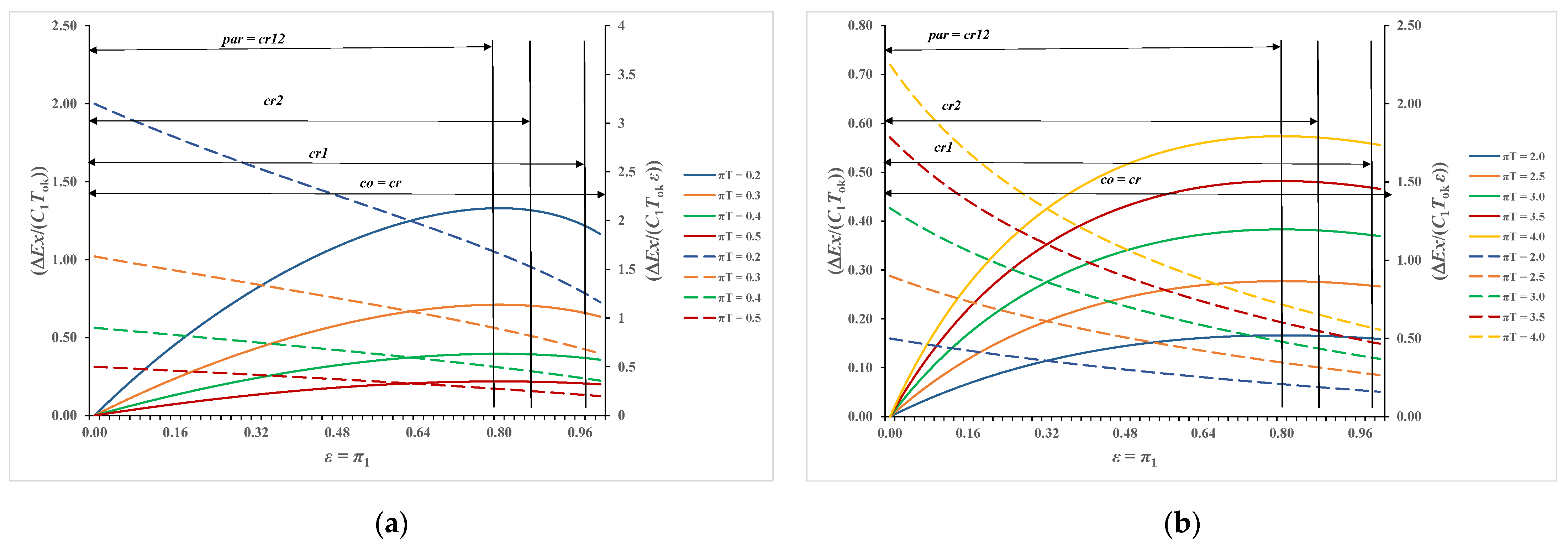
3.5. Presentation of the Ratio of Exergy Destruction to Effectiveness of the Recuperator

3.5.1. Case π3 = 0.0

The diagram in Figure 13a,b shows the exergy destruction as well as the ratio of exergy destruction to effectiveness of the recuperator in the case when a stronger stream evaporates or condenses. The value of ε is between 0.0 and 1.0. The value of these quantities is independent of the type of recuperator, which results from Equations (29) and (65). The maximum value of exergy destruction, according to Equation (55), is achieved at εstac = 1.0, which is in accordance with the diagram in Figure 13a,b, where continuous lines end with a horizontal tangent for ε = 1.0. For selected values πT = 0.2, 0.3, 0.4, 0.5 and 0.6, the respective maximum values are 2391, 1129, 0.584, 0.307 and 0.156. Dashed lines in Figure 13a show, according to Equations (65) and (66), values of the ratio of exergy destruction to effectiveness of the recuperator. This value, for a given πT, continuously decreases from the value determined with Equation (66) for ε = 0.0 to a value equal to maximum values of exergy destruction for ε = 1.0. Values of this ratio for ε = 0.0 with πT = 0.2, 0.3, 0.4, 0.5 and 0.6 respectively are 3.20, 1.633, 0.90, 0.50 and 0.267; for ε = 1.0, the respective values are, according to Equation (65), as follows: 2.391, 1.129, 0.584, 0.307 and 0.156.
Calculation results in Figure 13b represent the cases when πT > 1.0 for selected values πT = 2.0 to 4.0 with a step of 0.5. The left ordinate axis represents the values of exergy destruction, and the right ordinate axis represents the ratio of exergy destruction to effectiveness of the recuperator. Exergy destruction increases with the increase in ε from the value of zero to the maximum value that is determined with Equation (24). It is evident that in this case exergy destruction increases with increasing πT. The maximum values of exergy destruction, for selected πT = 2.0 to 4.0, are 0.193, 0.316, 0.432, 0.538 and 0.636. The right ordinate axis, related to the dashed lines, in Figure 13b, shows the ratio of exergy destruction to effectiveness of the recuperator as a function of ε and πT. It can be seen from the diagram that here too the ratio decreases with increasing ε and with decreasing πT. The ratio values for ε = 0.0 for the selected πT according to Equation (66) are 0.50, 0.90, 1.33, 1.78 and 2.25. The values of this ratio for ε = 1.0 are identical to the values of maximum exergy destruction indicated above. It is evident that with increasing πT there is a greater change in the ratio of exergy destruction to effectiveness of the recuperator.

3.5.2. Case π3 ≠ 0.0

In cases with π3 ≠ 0, the type of recuperator will be relevant both to the value of exergy destruction and to the value of the ratio of exergy destruction to effectiveness of the recuperator.
The diagrams in Figure 14a,b show the exergy destruction and the relevant ratio for π3 = 0.25.
The diagram in Figure 14a shows exergy destruction (continuous lines) and ratio (dashed lines) as a function of ε and πT where 0.20 ≤ πT ≤ 0.60 with a step of 0.10. It is interesting to note the fact that each parametric curve πT = const. has its own constraint related to the type of recuperator, so for parallel-flow (par) and cross-flow (cr12) recuperators, solutions apply only to the interval 0 ≤ ε ≤ 0.80 = εstac, since εstac equals 0.80 for all types of recuperators, according to Equation (51) and when π3 equals 0.25. For the value of εstac = 0.80 and the corresponding πT, according to Equation (53), all recuperators achieve the same value of the maximum exergy destruction and thus the same value of the ratio. Due to the value of εstac = 0.80 for parallel-flow (par) and cross-flow (cr12) recuperators, values greater than εstac can no longer refer to those types of recuperators. The constraint for cross-flow recuperator cr2 equals 0.885, and that for cross-flow recuperator cr1 is 0.982 while entire interval of ε refers to the counter-flow (co) and cross-flow (cr) recuperators. All these values are indicated by vertical lines in Figure 14a,b.
The diagrams in Figure 14a,b show that the value of exergy destruction continuously increases from zero to maximum with ε increasing from zero to εstac = 0.80 = εmax for parallel-flow (par) and cross-flow (cr12) recuperators. The values of these maxima decrease with increasing πT, as shown in Figure 14a, but further increase with increasing πT, as shown in Figure 14b. For all other cases, the values of exergy destruction reach the same maximum for a given πT and further decrease to the values shown at the ends cr2, cr1 and cr = co. These values can be easily read from the diagrams.
The diagrams in Figure 15 show a clearer meaning of the stated restrictions of individual recuperator types. Figure 15a,b represents the dependence of π2 on effectiveness for selected recuperators when π3 = 0.25. It is evident from these diagrams that for 0 ≤ εεstac = 0.80 and for the same ε and π3 value, π2par > π2k2 > π2k1 > π2co. This means that for the same values of heat transfer coefficient and heat capacity of the weaker stream there will be the following connection between heat exchanger area of the observed recuperators: A0par> A0cr2 > A0cr1 > A0co.

4. Conclusions

The paper presents dimensionless exergy destruction and the ratio of exergy destruction to effectiveness of a heat exchanger for all basic types of recuperators. The most important findings are as follows:
  • The obtained expressions enable detailed analysis of the quantitative influence of the dimensionless quantities π1 = ε, π2, π3 and πT both on the amount of exergy destruction and on the amount of the ratio of exergy destruction to effectiveness of the respective recuperator.
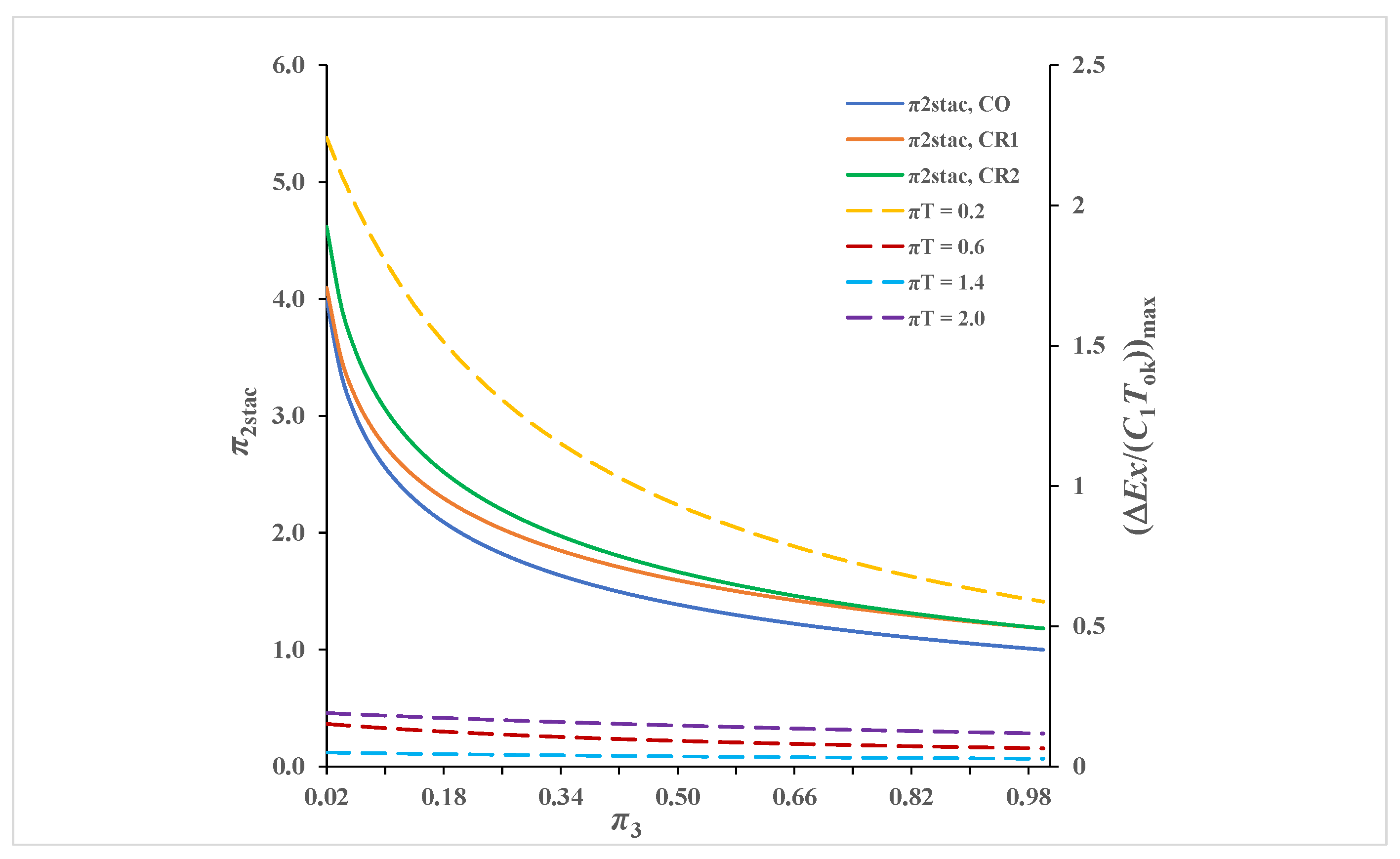
  • For all recuperators, derived analytical expressions explicitly determine the effectiveness of the recuperator εstac = 1/(1+π3) for which the maximum of exergy destruction occurs as a local extreme.
  • With the presented algorithm, it is possible to determine the operating point of the heat exchanger if either the value of dimensionless exergy destruction or the value of the ratio of exergy destruction to effectiveness is given as a criterion. For a given type of recuperator, the parameters of the recuperator operating point should be selected in a way that π2 is greater than π2stac, because in that case the exergy destruction is less than maximum and the value of the effectiveness is greater, which leads to the desired reduction in the ratio of exergy destruction to effectiveness.
  • For the parallel-flow and counter-flow recuperators, a local approach to the solution of exergy destruction is presented. This enables other local effects (such as stream pressure drop) to be built into this algorithm, with the optimization of local exergy destruction as a goal, involving more relevant effects. Moreover, it is possible to quantify the exergy destruction and the ratio of exergy destruction to effectiveness in respect to a higher number of streams passing through the heat exchanger [31], which is more often the practical case.

Author Contributions

Conceptualization, M.R. and A.G.; methodology, A.G. and M.R.; formal analysis, A.G.; investigation, M.R. and S.M.; writing—original draft preparation, M.R.; writing—review and editing, A.G. and S.M.; visualization, M.R. and S.M.; supervision, A.G. All authors have read and agreed to the published version of the manuscript.

Funding

This research received no external funding.

Institutional Review Board Statement

Not applicable.

Informed Consent Statement

Not applicable.

Data Availability Statement

Not applicable.

Conflicts of Interest

The authors declare no conflict of interest.

References

  1. Bošnjaković, F. Kampf den nichtumkehrbarkeiten. Arch. Wärmewirtsch. Dampfkesselwes. 1938, 19, 1–2. [Google Scholar]
  2. Rant, Z. Exergie, ein neues wort für technische arbeitsfähigkeit. Forsch. Geb. Ing. 1956, 22, 36–37. [Google Scholar]
  3. Gouy, M. Sur l’énergie utilizable. J. Phys. 1889, 8, 501–518. [Google Scholar]
  4. Stodola, A. Steam and Gas Turbines, 1st ed.; McGraw-Hill: New York, NY, USA, 1910. [Google Scholar]
  5. Bejan, A. Fundamentals of exergy analysis, entropy generation minimization, and the generation of flow architecture. Int. J. Energy Res. 2006, 26, 545–565. [Google Scholar] [CrossRef]
  6. Yilmaz, M.; Sara, O.N.; Karsli, S. Performance evaluation criteria for heat exchangers based on second law analysis. Int. J. Exergy 2001, 4, 278–294. [Google Scholar] [CrossRef]
  7. Manjunath, K.; Kaushik, S.C. Second law thermodynamic study of heat exchangers: A review. Renew. Sustain. Energy Rev. 2014, 40, 348–374. [Google Scholar] [CrossRef]
  8. Sepehr, M.; Hashemi, S.S.; Rahjoo, M.; Farhangmehr, V.; Alimoradi, A. Prediction of heat transfer, pressure drop and entropy generation in shell and helically coiled finned tube heat exchangers. Chem. Eng. Res. Des. 2018, 134, 277–291. [Google Scholar] [CrossRef]
  9. Genić, S.; Jaćimović, B.; Petrović, A. A novel method for combined entropy generation and economic optimization of counter-current and co-current heat exchangers. Appl. Therm. Eng. 2018, 136, 327–334. [Google Scholar] [CrossRef]
  10. Guzmán, J.E.V.; Hernández-Arrieta, I.; Vicente, W.; Salinas-Vazquez, M.; Martínez-Espinosa, E. Non-local entropy evolution in heat exchangers with elliptical and circular tube geometries. Int. J. Therm. Sci. 2018, 134, 601–611. [Google Scholar] [CrossRef]
  11. Goh, L.H.K.; Hung, Y.M.; Chen, G.M.; Tso, C.P. Entropy generation analysis of turbulent convection in a heat exchanger with self-rotating turbulator inserts. Int. J. Therm. Sci. 2021, 106, 106652. [Google Scholar] [CrossRef]
  12. Etghani, M.M.; Baboli, S.A.H. Numerical investigation and optimization of heat transfer and exergy loss in shell and helical tube heat exchanger. Appl. Therm. Eng. 2017, 121, 294–301. [Google Scholar] [CrossRef]
  13. Wang, J.; Hashemi, S.S.; Alahgholi, S.; Mehri, M.; Safarzadeh, M.; Alimoradi, A. Analysis of exergy and energy in shell and helically coiled finned tube heat exchangers and design optimization. Int. J. Refrig. 2018, 94, 11–23. [Google Scholar] [CrossRef]
  14. Alimoradi, A. Investigation of exergy efficiency in shell and helically coiled tube heat exchangers. Case Stud. Therm. Eng. 2017, 10, 1–8. [Google Scholar] [CrossRef]
  15. Al-Salem, K.; Hosseini, E.; Nohesara, A.; Mehri, M.; Ali, M.; Almuzaiqer, R.; Alimoradi, A.; Tlili, I. Suggestion of new correlations for the exergy efficiency and coefficient of exergy performance of annulus section of conically coiled tube-in-tube heat exchangers. Chem. Eng. Res. Des. 2019, 152, 309–319. [Google Scholar] [CrossRef]
  16. Wilhelmsen, Ø.; Berstad, B.; Aasen, A.; Nekså, P.; Skaugen, G. Reducing the exergy destruction in the cryogenic heat exchangers of hydrogen liquefaction processes. Int. J. Hydrogen Energy 2018, 10, 5033–5047. [Google Scholar] [CrossRef] [Green Version]
  17. Abu-Hamdeh, N.H.; Bantan, R.A.R.; Alimoradi, A. Heat transfer optimization through new form of pin type of finned tube heat exchangers using the exergy and energy analysis. Int. J. Refrig. 2020, 117, 12–22. [Google Scholar] [CrossRef]
  18. Guan, B.; Liu, X.; Zhang, T. Exergy analysis on optimal desiccant solution flow rate in heat exchanger for air dehumidification using liquid desiccant. Int. J. Refrig. 2021, 128, 129–138. [Google Scholar] [CrossRef]
  19. Xie, J.H.; Cui, H.C.; Liu, Z.C.; Liu, W. Optimization design of helical micro fin tubes based on exergy destruction minimization principle. Appl. Therm. Eng. 2022, 200, 117640. [Google Scholar] [CrossRef]
  20. Sundar, L.S.; Punnaiah, V.; Sharma, K.V.; Chamkhad, A.J.; Sousaa, A.C.M. Thermal entropy and exergy efficiency analyses of nanodiamond/water nanofluid flow in a plate heat exchanger. Diam. Relat. Mater. 2021, 120, 108648. [Google Scholar] [CrossRef]
  21. Li, Z.; Sheikholeslami, M.; Jafaryar, M.; Shafee, A.; Chamkha, A.J. Investigation of nanofluid entropy generation in a heat exchanger with helical twisted tapes. J. Mol. Liq. 2018, 266, 797–805. [Google Scholar] [CrossRef]
  22. Bahiraei, M.; Mazaheri, N. A comprehensive analysis for second law attributes of spiral heat exchanger operating with nanofluid using two-phase mixture model: Exergy destruction minimization attitude. Adv. Powder Technol. 2021, 32, 211–224. [Google Scholar] [CrossRef]
  23. Saleh, B.; Sundar, L.S. Experimental study on heat transfer, friction factor, entropy and exergy efficiency analyses of a corrugated plate heat exchanger using Ni/water nanofluids. Int. J. Therm. Sci. 2021, 165, 106935. [Google Scholar] [CrossRef]
  24. Bošnjaković, F. Nauka o Toplini, II Dio, 4th ed.; Tehnička knjiga: Zagreb, Croatia, 1976. [Google Scholar]
  25. Galović, A. Termodinamika II, 7th ed.; FSB: Zagreb, Croatia, 2019. [Google Scholar]
  26. Sekulić, D.P. Entropy generation in heat exchanger. Heat Transf. Eng. 1986, 2, 83–88. [Google Scholar] [CrossRef]
  27. Bošnjaković, F. Nauka o Toplini, I Dio, 5th ed.; Tehnička Knjiga: Zagreb, Croatia, 1978. [Google Scholar]
  28. Galović, A. Termodinamika I, 8th ed.; FSB: Zagreb, Croatia, 2021. [Google Scholar]
  29. Shah, R.K.; Sekulić, D.P. Fundamentals of Heat Exchanger Design; John Wiley & Sons: Hoboken, NJ, USA, 2003. [Google Scholar]
  30. Cengel, Y.A. Heat Trasnfer, A Practical Approach, 2nd ed.; McGraw-Hill: Boston, MA, USA, 2003. [Google Scholar]
  31. Roetzel, W.; Spang, B. C1 Thermal Design of Heat Exchangers. In VDI Heat Atlas, 2nd ed.; Stephen, P., Kabelac, S., Eds.; Springer: Berlin/Heidelberg, Germany, 2010; pp. 33–62. [Google Scholar]
Figure 1. The derivation of local exergy destruction in (a) parallel-flow and (b) counter-flow heat exchangers.
Processes 10 00249 g001
Figure 2. Characteristic π2 values and temperature streams in the balanced counter-flow recuperators A, B and C: (a) ΔTout > 0. (b) ΔTout = 0. (c) ΔTout < 0.
Processes 10 00249 g002
Figure 3. Characteristic π2 values and temperature streams in the counter-flow recuperators A, B and C: (a) ΔTout > 0. (b) ΔTout = 0. (c) ΔTout < 0.
Processes 10 00249 g003
Figure 4. Exergy balance of the heat exchanger [26].
Processes 10 00249 g004
Figure 5. Local exergy destruction of a parallel-flow recuperator for πT = 0.50 and 2.0: (a) π3 = 0.50; (b) π3 = 1.0.
Processes 10 00249 g005
Figure 6. Local exergy destruction of a counter-flow recuperator for πT = 0.50 and 2.0: (a) π3 = 0.50; (b) π3 = 1.0.
Processes 10 00249 g006
Figure 7. Local exergy destruction of a recuperator for π3 = 0.0: (a) πT = 0.50; (b) πT = 2.0.
Processes 10 00249 g007
Figure 8. Dependence of exergy destruction on π2 and πT with π3 = 0.0.
Processes 10 00249 g008
Figure 9. Dependence of exergy destruction on π2 for πT = 0.50 and π3 = 0.50: (a) 0 < π2 < 8.0; (b) 0.8 < π2 < 2.3.
Processes 10 00249 g009
Figure 10. Dependence of exergy destruction on π2 for πT = 2.0 and π3 = 0.50: (a) 0 < π2 < 8.0; (b) 1.2 < π2 < 2.2.
Processes 10 00249 g010
Figure 11. Dependence of exergy destruction on π2 for πT = 0.5 and π3 = 1.0: (a) 0 < π2 < 8.0; (b) 0.8 < π2 < 1.8.
Processes 10 00249 g011
Figure 12. Dependence of π2stac and (∆Ex/(C1Tok))max on πT and π3.
Processes 10 00249 g012
Figure 13. Dependence of exergy destruction and the ratio of exergy destruction to effectiveness of the recuperator on ε and πT for π3 = 0.0: (a) 0.2 < πT < 0.5; (b) 2.0 < πT < 4.0.
Processes 10 00249 g013
Figure 14. Dependence of exergy destruction and the ratio of exergy destruction to effectiveness of the recuperator on ε and πT for π3 = 0.25: (a) 0.2 < πT < 0.5; (b) 2.0 < πT < 4.0.
Processes 10 00249 g014
Figure 15. Dependence of π2 on effectiveness of recuperator with π3 = 0.25: (a) 0 < ε < 1.0; (b) 0 < ε < 0.7.
Processes 10 00249 g015
Table 1. Dependence of π2stac on π3 for recuperators cr and cr12.
π3π2stac (cr)π2stac (cr12)
0.251.9742.37
0.501.5201.74
0.751.2901.44
1.001.1501.26
Publisher’s Note: MDPI stays neutral with regard to jurisdictional claims in published maps and institutional affiliations.

