Article

Optimization Analysis of Locomotive Diesel Engine Intake System Based on Matlab-Simulink and GT-Power

1
School of Mechanical and Automotive, Guangxi University of Science and Technology, Liuzhou 545006, China
2
Guangxi Key Laboratory of Automobile Components and Vehicle Technology, Guangxi University of Science and Technology, Liuzhou 545006, China
*
Author to whom correspondence should be addressed.
Processes 2022, 10(1), 157; https://doi.org/10.3390/pr10010157
Submission received: 27 December 2021 / Revised: 11 January 2022 / Accepted: 11 January 2022 / Published: 13 January 2022
(This article belongs to the Special Issue Clean Combustion and Emission in Vehicle Power System)

Abstract

:
In this paper, based on the coupling calculation of Simulink software and GT-Power software, an Optimizer model method was proposed for a 16V265H diesel engine to study the effects of different ratios of biodiesel (B0, B10, and B20) on the performance of a 16V265H diesel engine at 1000 rpm and 75% load. Firstly, the four parameters of diesel engine power, BSFC, soot emission, and NOx emission were taken as the result variables of the optimization model. Taking the intake and exhaust timing of the diesel engine as the independent variable of the optimization model, the maximum power, minimum BSFC, and minimum diesel engine emission were studied and analyzed. Finally, the performance parameters were comprehensively analyzed to determine the best intake and exhaust valve timing. Moreover, based on the model optimization, the diesel engine’s BSFC and power performance were compared, and the optimal intake timing scheme for the diesel engine with different biodiesel ratios at 75% operating conditions was obtained. The results showed that the maximum power, optimum BSFC, and minimum emissions of the 16V265H diesel engine with different ratios of biodiesel and different intake valve timing angles were also different. Under 75% load conditions, the BSFC reduction rate was up to 6.32%, and the power increase rate was up to 5.87%. In addition, by optimizing the model with B10 biodiesel and the intake valve timing close to 202°CA and the exhaust valve timing close to 98°CA, the diesel engine had the lowest NOx emission; with B10 biodiesel and the intake timing at 180°CA, the diesel engine had the lowest BSFC; and with B10 biodiesel and the intake valve timing close to 179.5°CA, the diesel engine had the maximum power. In conclusion, the diesel engine is best with B10 biodiesel. This research method can provide a reference for implementing variable intake system technology for the 16V265H diesel engine.

1. Introduction

In recent years, with the rapid development of rail transit equipment worldwide [1] the requirements for a high-speed and heavy-load of railway freight are higher and higher [2,3]. In order to meet the market demand, the American EMD company has produced a 6000 HP HXN3 diesel locomotive [4]. The locomotive adopts the world’s most advanced 16V265H low emission four-stroke diesel engine. After years of technical renewal and development, the diesel engine has realized quantitative production [5]. The innovative use of biodiesel in a high-power locomotive diesel engine is a cutting-edge technology to deal with the world’s energy shortage [6] and increasingly stringent emission regulations [7], and to improve the operational performance of locomotive diesel engines, which helps to improve the emission [8], economy [9], and power performance of locomotive diesel engines [10].
The structural parameters and design parameters of diesel engines, such as cylinder diameter, piston stroke, compression ratio, fuel injection system parameters, valve phase value, and intake and exhaust system parameters [11,12] have a significant impact on the power, economy, and emission of a diesel engine [13]. Whether a diesel engine or gasoline engine, the structure and in-cylinder working process are extremely complex and changeable thermodynamic reaction processes, and fuel mixture combustion is accompanied by many physical and chemical reactions [14].
Improving the performance of automotive internal combustion engines is the most demanding factor in the development of new engines [15]. The design of intake and exhaust systems can improve volumetric efficiency, so as to provide better torque and horsepower at specific engine speeds, which is necessary [16]. Many experts and scholars have conducted a lot of research and put forward many new technologies to improve engine combustion [17,18,19]. Therefore, when developing new technologies [20,21], it has become a challenge to improve the performance of automotive internal combustion engines, decide to use fuel better [22], and even seek the actual performance of such engines under transient and steady-state conditions [23].
In recent years, many researchers have engaged in the optimization analysis of engine intake systems. For example, Yang et al. [24] developed the GT-Power model of an engine intake system and analyzed the influence of harmonics on the intake system. In addition, the intake system was optimized by the response surface method. Qi et al. [25] developed a CFD model using Kiva and STAR-CD software to analyze the temperature, concentration, and flow field in the engine cylinder. Then, the intake system was optimized according to the relationship between intake system structure and cylinder flow. Similarly, Pai et al. [26] established the engine simulation model by using GT-power and STAR-CD software, and studied the influence of the intake system on engine performance. The results showed that the engine performance had been significantly improved. In addition, Silva et al. [27] established an engine simulation model using the GT-power model. The relationship between intake manifold volumetric efficiency and geometric parameters was analyzed by the Brent method and the intake system was optimized.
The application of computer simulation technology has dramatically improved and improved the research and development (R&D) and optimization of the traditional internal combustion engine, and the working process of the engine is modelled by simulation software, which can effectively predict the performance of the engine under different working conditions [28]. In order to improve the economic and environmental performance of diesel engines, many researchers have optimized and analyzed the engine intake system in recent years. For instance, Leahu et al. [29] proposed to drive a composite vehicle, running through a DC motor instead of a supercharged engine, to form a composite driven supercharged diesel engine. Depending on the speed and load of the diesel engine, the speed of the motor could be modified by an electronic management system to optimize the air intake system. Wang et al. [30] optimized the intake system by studying the synergistic effects of the fuel injection system, intake system, and combustion system on the combustion characteristics of a controlled intake cyclone diesel engine. Ma et al. [31] studied the effect of intake air temperature on intake efficiency and found that the intake losses decreased significantly with increasing intake air temperature; thus, the increase in intake air temperature helped improve intake air efficiency. Kang et al. [32] used a diesel particulate filter with intake and exhaust throttling to increase the piston pumping, thus optimizing the intake system. Similarly, Cheng et al. [33] widely installed variable geometry turbochargers and exhaust gas recirculation valves on diesel engines to optimize intake airflow control and exhaust gas recirculation ratio. Li et al. [34] investigated smart charge compression ignition, a new dual-fuel combustion mode, by optimizing the intake pressure and thus the intake system. The decrease in exhaust pressure and the rapid increase in intake pressure leads to a pressure difference on the circulating valve. Therefore, Song et al. [35] investigated the auxiliary pressurization technology and determined that there is a trade-off between exhaust and intake to optimize the intake system. Zhen et al. [36] developed a simulation model of a four-cylinder ignition methanol engine using one-dimensional simulation software to study the effects of throttle opening at 30%, 50%, and 70% on engine performance, combustion, and emissions to find the optimal throttle opening for optimization of the intake system. In addition, Arnau et al. [37] developed a one-dimensional gas dynamics engine model to simulate several variable exhaust valve driving strategies, which provided the best trade-off between exhaust temperature increase and BSFC by using a variable valve assembly strategy for advanced exhaust (early exhaust valve opening and early exhaust valve closing) and delayed intake (late intake valve opening and late intake valve closing) to optimize the diesel engine intake system.
As mentioned earlier, the numerical simulation of internal combustion engine has obvious advantages. Through the detailed mathematical framework, it is considered to be a very effective tool to save experimental costs [38,39]. In this paper, a novel optimization model is used to simulate the intake combustion process. Based on the optimization model, the timing performance index of the intake valve is calculated and compared [40,41]. This paper mainly studies that a 16V265H diesel engine burns three different ratios of biodiesel B0, B10 and B20 at 1000 rpm and 75% load. The parameters such as diesel engine power, BSFC, soot emission and NOx emission are taken as the result variables of the model. The intake timings of the diesel engine (including intake valve opening (IVO), intake valve closing (IVC), exhaust valve opening (EVO) and exhaust valve closing (EVC)) are taken as the independent variables of the optimization model to determine the optimal valve timing of a 16V265H diesel engine at 1000 rpm and under 75% load condition.

2. Numerical Approaches

The working process of the diesel engine in-cylinder includes complex and integrated processes such as heat transfer, flow, physics, and chemistry. Its basic differential equation is one of the most fundamental equations in simulation calculation [42]. In addition, in diesel engine engineering technology, optimization technology plays a very important role and significance in the process of diesel engine development decision making [43].

2.1. Theory of Diesel Engine Working Process

The core equation of the diesel engine working process simulation software GT-Power module involved in this paper is the basic differential equation of the working process in the cylinder, which is extended to the calculation of combustion, emission, and other models [44]. At the same time, the calculation results of the basic differential equation are used to determine whether the flow coefficient and pressure coefficient of the diesel engine converge.
The combustion and heat transfer processes of the cylinder follow certain rules. The basic equations of the working process of the cylinder are as follows:
(1) Energy conservation equation:
The first law of thermodynamics leads to the following equation:
d U d φ = d Q B d φ + d m s d φ h s d m e d φ h e d Q w d φ p d V d φ
where U is the internal energy of the system, J; QB is the heat energy released by the combustion of fuel in the cylinder, J; Qw is the heat energy exchanged through the interfaces of the cylinder system, J; hs and he are the specific enthalpies of working medium at intake valve and exhaust valve, J; ms and me is the mass of working medium at intake valve and exhaust valve, kg, p is the working medium pressure in the cylinder, Pa; φ is the crank angle, ◦; and V is the working volume of the cylinder, m3.
(2) Mass conservation equation:
d m d φ = d m s d φ + d m e d φ + d m B d φ
where m is the mass of fuel in the cylinder, g; mB is the instantaneous mass of fuel injected into the cylinder, g.
(3) Equation of state of an ideal gas:
p V = m R T
where T is the working temperature in the cylinder, K; and R is the gas constant.

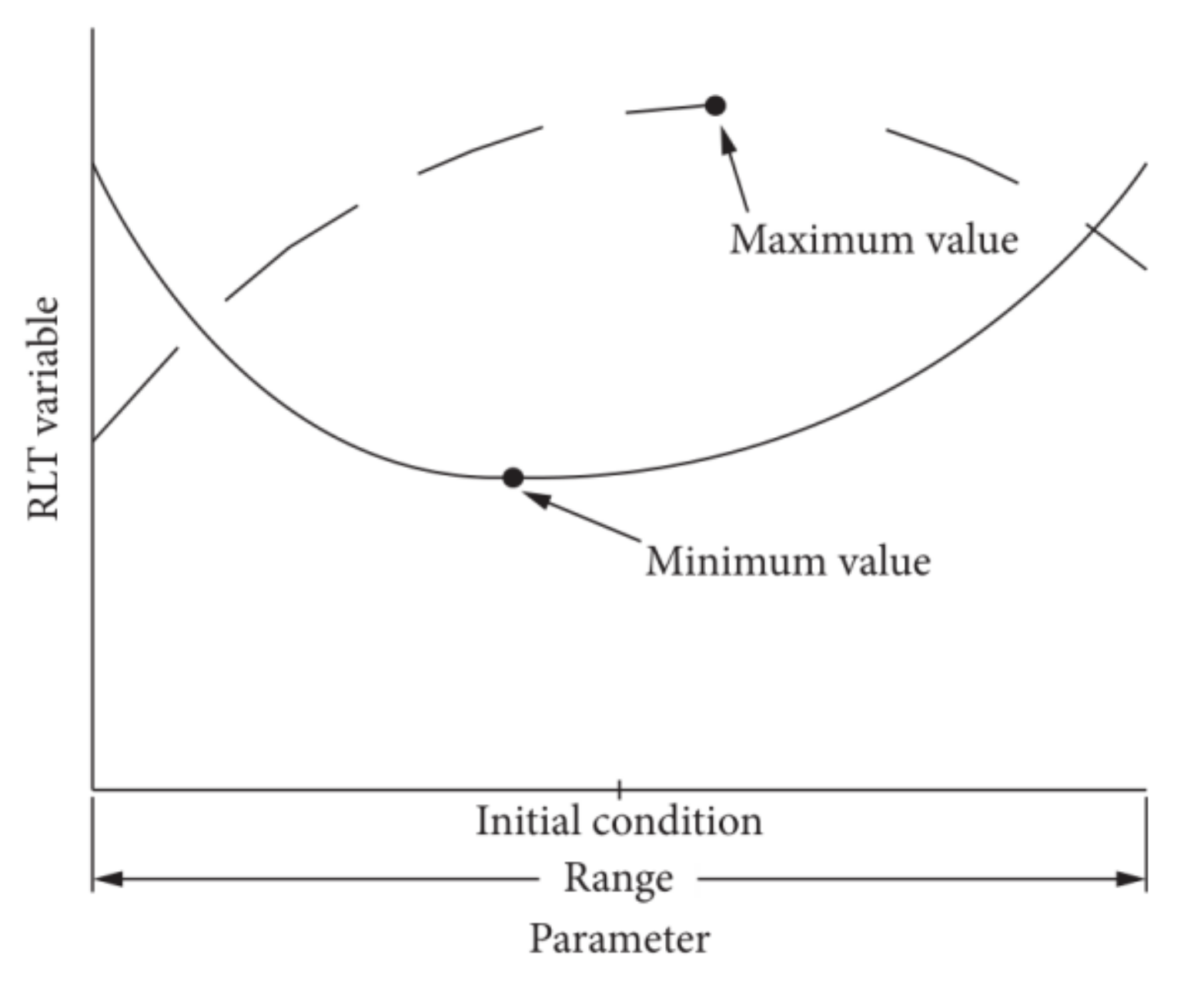
2.2. Theoretical Basis of Optimization Methods for Diesel Engine Applications

In this paper, through the Simulink module of Matlab software, the optimization objective function and constraints were given, the optimization model was established, and coupled with GT-Power software to form an innovative Optimizer model for the related optimization design.
The Optimizer optimization model’s objective function is set as a real-time variable (RLT variable) that changes with the design variable. By selecting an appropriate iterative method, a series of optimization design vector sequences are generated to obtain objective function value sequences. When the objective function value sequences converge, the sequences eventually tend to the optimal solution. The optimization model optimizer formed by two simulation software usually has two optimization algorithms, namely, the discrete grid method or Brent search method, which can solve this kind of optimization problem [45].
In order to facilitate the study of the optimization method, taking the power of a 16V265H diesel engine as an example, under the premise of determining other parameters, Pe can be expressed as a function of the intake and exhaust valve timing angle φB, φC. The research shows that the power also changes with intake and exhaust valve timing angle. In order to obtain better power, the optimization mathematical model can be written as follows:
min P e = f 1 ( x ) , x = [ φ B , φ C ] T s t . 149 . 5 x ( 1 ) 269 . 5   76 x ( 2 )   196
The optimization objective function in Equation (4) is generally difficult to obtain directly. When the diesel engine speed is determined, it is easy to obtain the two-dimensional contour map (i.e., the level set of binary function) between the objective function and the optimization variable under discrete variables by using GT-Power software. Similarly, the mathematical model of BSFC and emission can be obtained.
According to the optimization theory, given the initial search point x0, it is not difficult to determine that its negative gradient direction is the direction in which the function value decreases the fastest, so it is determined that the new search point is:
x 1 = x 0 α 0 f 1 ( x 0 )
When the positive real number α0 takes different values, the new search points will be different, and the function values will be different. As shown in Figure 1, the function values of x1(0) and x1(1) obtained at different α 0 0 and α 0 1 are different. At this time, the value of f1(x1) changes with variable α0, that is, f1(x1) = ψ1(α0). In order to obtain the minimum value of f1(x), it is necessary to take the extreme value of all function values, namely:
ψ 1 ( α 0 ) α 0 = g ( α 0 ) = 0
In order to obtain the solution of Equation (6), GT-Power usually uses the Brent method [27] to determine the value of α0.
As shown in Figure 1, the Brent method is a faster search method combining dichotomy, linear interpolation, and inverse quadratic interpolation. Its specific operations are as follows:
Firstly, the initialization interval [a0, b0] of α0 is given so that g(a0)·g(b0) < 0. The estimated value of the iterative root in step k is recorded as α 0 k = b k (if g ( a k ) < g ( b k ) , α 0 k = a k ), and the estimated values of the iterative roots in the first two steps are recorded as bk−1 and bk−2, respectively. Judge whether the following four inequalities are true:
δ < b k b k 1
δ < b k 1 b k 2
s b k < 1 2 b k b k 1 ,   s = a k   or   b k
s b k < 1 2 b k 1 b k 2
Judge whether any one of the following five conditions are true:
(1)
The k−1st iteration is dichotomous and (7) does not hold;
(2)
The k−1st iteration is dichotomous and (8) does not hold;
(3)
The k−1st iteration is an interpolation and (9) does not hold;
(4)
The k−1st iteration is an interpolation and (10) does not hold;
(4)
The temporary value s calculated by the interpolation method is not in the interval 3 a k + b k 4 , b k .
If yes, the iterative value α 0 k + 1 of the current root is obtained by dichotomy:
α 0 k + 1 = 1 2 a k + b k
Otherwise, judge whether the following formula is true:
α 0 k 1 α 0 k ,    α 0 k 1 α 0 k + 1 ,    α 0 k α 0 k + 1
If Equation (12) holds, then
α 0 k + 1 = g ( α 0 k 1 ) g ( α 0 k ) g ( α 0 k 2 ) g ( α 0 k 1 ) g ( α 0 k 2 ) g ( α 0 k ) α 0 k 2 + g ( α 0 k 2 ) g ( α 0 k 1 ) g ( α 0 k ) g ( α 0 k 2 ) g ( α 0 k ) g ( α 0 k 2 ) α 0 k + g ( α 0 k 2 ) g ( α 0 k ) g ( α 0 k 1 ) g ( α 0 k 2 ) g ( α 0 k 1 ) g ( α 0 k ) α 0 k 1
If Equation (12) does not hold, then
α 0 k + 1 = b k ( b k a k ) g ( b k ) g ( b k ) g ( a k )
It should be noted that for the temporary value s = α 0 k + 1 in the above Equations (9) and (10), after each iteration, the interval [ak, bk] of the root will be further reduced to [ak+1, bk+1], where ak+1 = s or bk+1 = s, and the other endpoint is one of ak and bk, and the following conditions are met:
g ( a k + 1 ) g ( b k + 1 ) < 0 ,   and   g ( a k + 1 ) > g ( b k + 1 )
Repeat the above iteration until α0 converges, that is, the interval length of the solution tends to an infinitesimal value.
a k + 1 b k + 1 ε 1
By analogy, it is not difficult to construct the iterative point sequence as follows:
x k + 1 = x k α k f 1 ( x k ) ,    ( k = 1 , 2 , )
In addition, in each iteration step, the positive real number αk can be determined according to the following equation:
ψ 1 ( α k ) α k = 0
Until the sequence satisfies the following convergence conditions:
x k + 1 x k ε
In Equation (19), is the norm of the vector and ε is a minimal positive real value.
In the subsequent optimization calculation in this paper, because the design variables are two (intake and exhaust timing angles), the problem can be expressed as a constrained optimization problem and the Brent method can be used for optimization design. At the same time, according to the design variables generated by each iteration data and their corresponding objective function values, the contour map (i.e., cloud map type) of the objective function varying with the design variables will be generated to present the optimization design process in a more intuitive form.

2.3. Optimizer Model

As an optimization model, when the optimization result variable is the maximum or minimum value, its change needs to meet the following trend: the result variable first increases to the maximum value and then decreases, or decreases to the minimum value and then increases (i.e., the only maximum or minimum value) with the independent variable (giving the initial value, setting the independent variable range and step accuracy). The optimization result variable is shown in Figure 2.
It can be seen from Figure 2 that the Optimizer model works by running the calculation until it reaches a stable state (one iteration), then resetting one or more parameters and running again until the optimal value is found. This structural feature can obtain stable iterative calculation. The optimizer optimization model is coupled with GT-Power software through the Matlab software Simulink module. After debugging and running Simulink, the GT-Power is mobilized to the optimized algorithm.
It can be seen from the changing trend in Figure 2 that the parameters including power, torque, BSFC, emission and inflation efficiency in each performance index of the internal combustion engine can be used as the result variables of the Optimizer optimization model, while the independent variable parameters including intake and exhaust timing, throttle opening, and important structural parameters can be used as the independent variables of the Optimizer optimization model. At present, the author is optimizing the valve timing of a gasoline engine under various working conditions based on the Optimizer model and taking the inflation efficiency as the optimization objective, so as to determine the optimal valve timing angle at various speeds and improve the engine performance to a certain extent.

2.4. Fuel Properties

The typical biodiesels are mainly composed of five components, methyl linolenate (C18:3), methyl linoleate (C18:2), methyl oleate (C18:1), methyl stearate (C18:0), and methyl palmitate (C16:0). Cm:n is the shorthand of fatty acid methyl esters (FAME), n is the number of double bonds, and m is the number of carbon atoms. It is generally believed that the major components of typical biodiesels are also the above five components, and other components such as C12:0, C14:0, and C20:0 can be ignored. Soybean oil methyl ester (SME) was obtained from soybean oil and methanol by transesterification. The transesterification of soybean oil was carried out under the catalysis of alkali, and the reaction time was about 1 h. The molar ratio of methanol to oil is 6:1, and the alkali catalyst is 1% wt/wt KOH. Based on the fatty acid profile, the SME properties were analyzed by “Biodiesel Analyzer”. The main instruments and test standards for physical and chemical property tests are shown in Table 1. In the paper, an Agilent 7890 N GC-MS analyzer was used for measuring the composition of fatty acids of biodiesel. Table 2 shows the fatty acid profile of biodiesel [10,46,47,48]. In addition, the kinematic viscosity of biodiesel is measured according to ASTM D445. Similarly, the lower calorific value of biodiesel is measured according to ASTM D240.
The biodiesel made from 0# diesel and soybean “wool” oil was blended with 0%, 10%, and 20% volume fractions (recorded as B0, B10, and B20) to determine the compatibility, cold filter point, freezing point, density, cetane number, kinematic viscosity, flash point, etc., respectively. The main experimental equipment is: DYS-006B pour point, cloud point, freezing point, cold filtration point tester; kinematic viscosity determination thermostat bath; BSH-2 closed-end flash tester; DSY-020 copper corrosion turbidity tester for petroleum products; DSS-1 petroleum products moisture tester; and DRD-100 automatic distillation tester, etc. The test results are shown in Table 3.

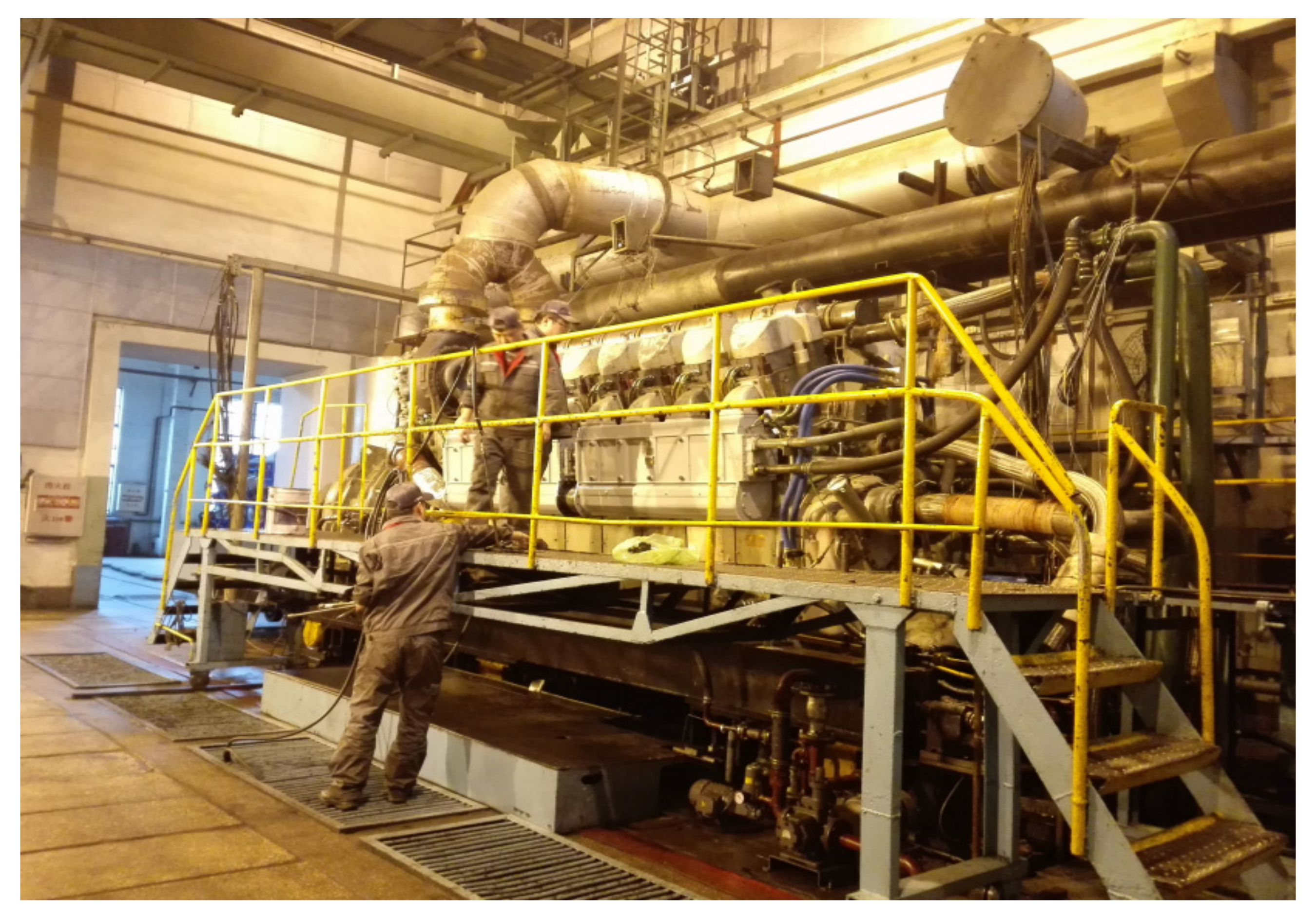
2.5. Engine Specifications

The 16V265H diesel engine adopts turbocharging and electronically controlled unit pump fuel injection technology with a rated power of 4660 kw, rated speed of 1000 rpm, and displacement of 264.74 L. The main technical parameters are shown in Table 4. The layout of the diesel engine bench test room is shown in Figure 3. The simulation model of the entire diesel engine is shown in Figure 4.

3. Results and Discussion

Because 1000 rpm and 75% load are the most common operating conditions of the locomotive diesel engine [4], in this paper, biodiesel with different ratios was studied (B0, B10, and B20) on the performance of the 16V265H diesel engine under 75% load condition at 1000 rpm. Firstly, the four parameters of diesel engine power, BSFC, soot emission, and NOx emission are taken as the result variables of the Optimizer optimization model. The intake and exhaust timings of the diesel engine are taken as the independent variables of the Optimizer optimization model to study and analyze the maximum power, minimum BSFC, and minimum exhaust emission. Finally, the performance parameters are comprehensively analyzed to determine the optimal intake and exhaust valve timing. This research method can provide a reference for a 16V265H diesel engine to realize variable intake system technology.

3.1. Power Optimization Analysis of 16V265H Diesel Engine

Figure 5 shows the optimal calculation results of maximum power generated by a 16V265H diesel engine burning biodiesel with different ratios (B0, B10, and B20) at 1000 rpm and 75% load. As can be seen from the figure, the more concentrated the red area means that the optimization result is closer to the target value, and the more concentrated the distribution of points in the red area means that the area is closer to the optimal target value area.
As can be seen from Figure 5a, the diesel engine is in the combustion of pure diesel B0 and the maximum power region appears around 217°CA at intake valve timing. Judging from the cloud map, as the intake valve timing increases from the minimum range angle of 149.5°CA to 180°CA, the power value changes little; when the intake valve timing angle is greater than 180°CA, the power calculation value is incremented; and when the maximum region is 217°CA, the timing angle continues to increase and the power shows a downward trend. From the color change trend in the cloud diagram, it can be seen that the power value has the maximum value within the optimization calculation range, and it increases first and then decreases with the increase in valve timing angle. The power has a unique maximum target value within a given calculation range, which is in line with the theory of the Optimizer optimization model. Judging from the calculation results, the intake valve closing delay is about 8°CA (that is, the intake valve timing is around 217°CA), and the output power of the diesel engine has a maximum region.
As can be seen from Figure 5b, in the vicinity of intake valve timing from 165°CA to 194.5°CA, the maximum power optimization dense distribution region appears. This is because the valve overlap angle in the valve timing range corresponds to a large amount of intake air flow, the fuel gas mixture in the cylinder is fully mixed and the combustion effect is good, and the power increases accordingly. Judging from the calculation results, the intake valve closing needs to be delayed by about 30°CA (that is, the intake valve timing is near 179.5°CA); the output power of the diesel engine has a maximum area.
As can be seen from Figure 5c, when B20 biodiesel is used, the maximum power region of the diesel engine is around 179.5°CA at the positive valve timing. Judging from the cloud map, extremely low power occurs in two areas near the intake valve timing of 209.5°CA (initial intake valve timing angle) and the intake valve timing of 259.5°CA.
As can be seen from Figure 5, the 16V265H diesel engine uses different ratios of biodiesel (B10, B20) at a speed of 1000 rpm and 75% load. The maximum output power is the optimized target value, and the intake valve is closed about 30°CA in advance (that is, the intake valve timing is around 179.5°CA); the diesel engine has the highest output power. When B0 pure diesel is used, the intake valve closing needs to be delayed by about 8°CA (that is, the intake valve timing is around 217°CA); at this time, the output power of the diesel engine is the maximum.
It can be seen from Figure 6 that the power value of the diesel engine after optimization is higher than the power value before optimization, and when the ratios of biodiesel increase (such as B10 to B20), the power of the diesel engine shows a slightly decreasing trend. The power value of the diesel engine burning B10 and B20 biodiesel is slightly lower than that of B0 pure diesel. Therefore, there is strong practical significance for the use of low-ratio biodiesel (such as: B10, B20).
It can be seen from Figure 5 and Figure 6 that after optimizing based on the Optimizer model, the output power of the diesel engine fueled with various ratios of biodiesel has been increased, and the output power is higher than the original engine’s initial valve timing angle (the initial intake valve timing angle is 209.5°CA) generated power. The optimized diesel engine can greatly improve the oil–gas mixing effect and increase the output power of the diesel engine. The output power of this diesel engine when burning B10 and B20 biodiesel is slightly lower than the output power when burning B0 pure diesel. Based on the optimization results of the Optimizer model, it can be concluded that the optimal solution for the diesel engine to use different ratios of biodiesel under 75% load conditions is: B10 biodiesel with the intake valve timing at 179.5°CA (that is, the intake angle of the early door closing is 30°CA). This scheme can achieve the effect of maximizing the power of burning biodiesel fuel.

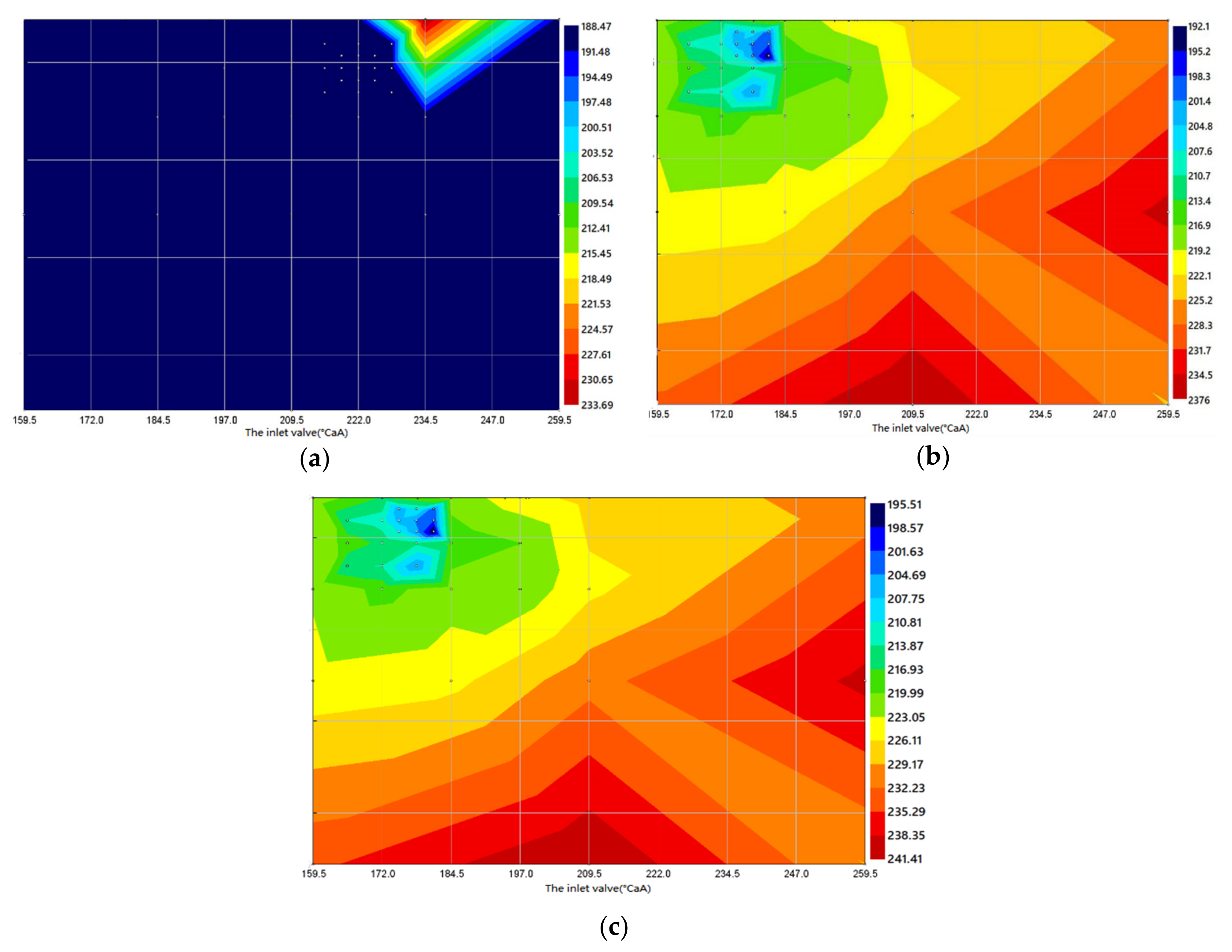
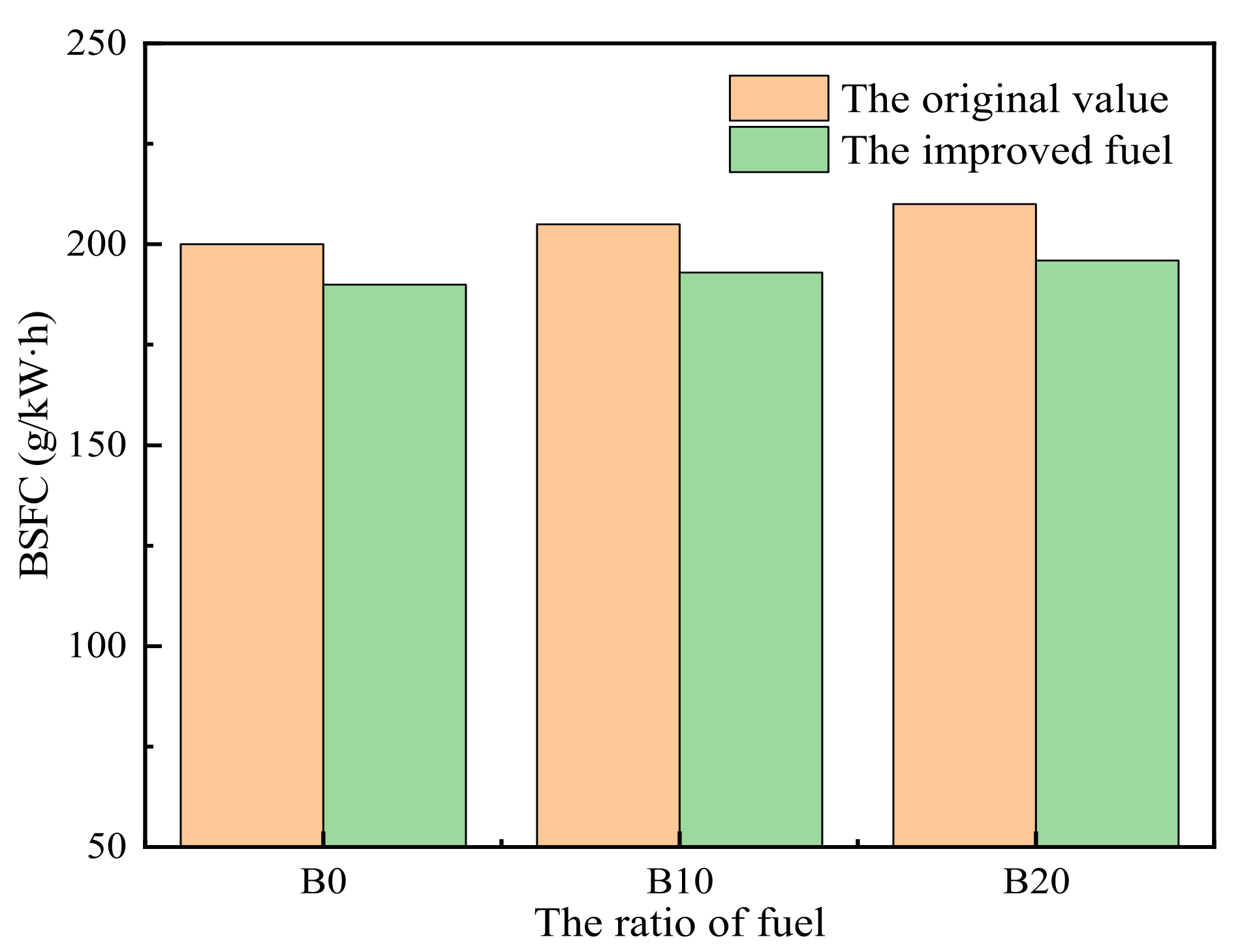
3.2. Analysis of Brake Specific Fuel Consumption Optimization of 16V265H Diesel Engine

Figure 7 shows the optimal calculation results of minimum brake specific fuel consumption (BSFC) by a 16V265H diesel engine burning biodiesel with different ratios (B0, B10, and B20) at 1000 rpm and 75% load.
As can be seen from Figure 7a, under the condition of B0 pure diesel, the diesel engine has the lowest BSFC near the intake valve timing of 222°CA. It can be seen from Figure 7b,c that the BSFC optimization results of B10 and B20 biodiesel have similar trends. All of them appear near the intake valve timing of 180°CA in a densely distributed small area with the lowest BSFC optimization; the difference between the intake and exhaust valve angles that need to be optimized and adjusted is small.
Based on the three diagrams in Figure 7, it can be concluded that the 16V265H diesel engine uses different ratios of biodiesel (B0, B10, and B20) at a speed of 1000 rpm and 75% load, with the lowest BSFC as the optimal target value. It can be determined that using B10 biodiesel has the best effect, and the closing of the intake valve needs to be delayed by about 29°CA (that is, the intake valve timing is 180°CA attached). This diesel engine has the lowest BSFC. When B0 pure diesel is used, the diesel engine has the lowest BSFC near the intake valve timing of 222°CA.
Figure 8 shows the BSFC optimization comparison of a 16V265H diesel engine at 1000 rpm and 75% load when using three different ratios of biodiesel. It can be seen from the figure that the BSFC of the diesel engine after model optimization is lower than the BSFC before optimization, and when the ratio of biodiesel increases (such as B0 to B10), the BSFC of the diesel engine slightly increases. When using B10 and B20 biodiesel, the diesel engine BSFC is slightly higher than that of pure diesel B0, and the BSFC increases with the increase in the biodiesel ratios This is because the calorific value of biodiesel is lower than the calorific value of B0 pure diesel. With an output of the same power, the amount of fuel required will increase. After optimization based on the model, the BSFC of diesel engines fueled by biodiesel at various ratios was reduced.
According to a comprehensive analysis, the Optimizer model is used to calculate the use of different ratios of biodiesel under 75% load conditions. It is concluded that the optimal solution under this operating condition is: B10 biodiesel is used, and the intake valve closing needs to be delayed by about 29°CA (that is, the intake valve timing is around 180°CA); the diesel engine has the lowest BSFC.

3.3. Optimization Analysis of Soot Emission from 16V265H Diesel Engine

Figure 9 shows the optimal calculation results of soot emission by a 16V265H diesel engine burning biodiesel with different ratios (B0, B10, and B20) at 1000 rpm and 75% load. The more concentrated the red area of the cloud map represents the greater the soot emission value; the denser the blue area and the more concentrated the point distribution represents the closer the area is to the optimal target value area.
It can be seen from Figure 9a that when the diesel engine uses pure diesel B0, the highest soot emission occurs in two areas near the intake valve timing of 239.5°CA and the intake valve timing of 254.5°CA. The soot emission is the lowest in the area centered around the intake valve timing of 264.5°CA (the area where the number of points is concentrated).
From Figure 9b, it can be seen from the soot emission optimization results produced when diesel engines use B20 biodiesel (B10 biodiesel optimization results are also similar) that the lowest soot emission is in the area centered around the intake valve timing of 264.5°CA. In the area centered around 254.5°CA at the intake valve timing, the maximum soot emission appears.
Figure 10 shows the soot emission optimization results of a 16V265H diesel engine fueled with different ratios of biodiesel under 1000 rpm and 75% load conditions. It can be seen from the figure that the optimized soot emission of the diesel engine has decreased significantly; the diesel engine has the lowest soot emission when using B20 pure biodiesel, and when the ratio of biodiesel increases, the soot emission of the diesel engine shows a downward trend. The highest soot emission is when B0 pure diesel is used, which shows that the use of biodiesel has the effect of reducing soot emission.
According to the calculation of the 16V265H diesel engine fueling different ratios of biodiesel under the operating condition of 1000 rpm and 75% load through the model, it is concluded that the optimal solution under this operating condition is: when B20 biodiesel is used, the soot emission of the diesel engine is the lowest when the intake valve timing is near 264.5°CA and the exhaust valve timing is near 191°CA. The effect of burning B10 biodiesel is the second optimal solution.

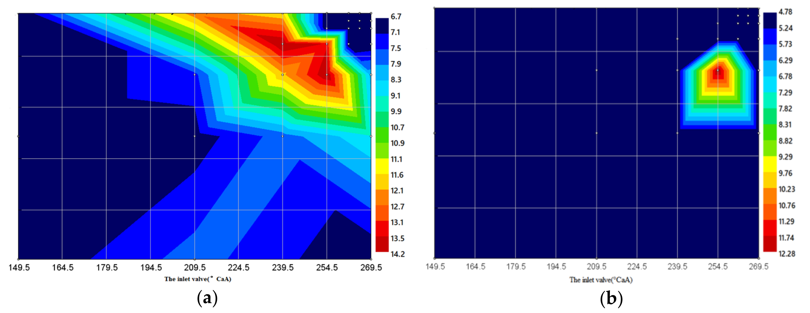
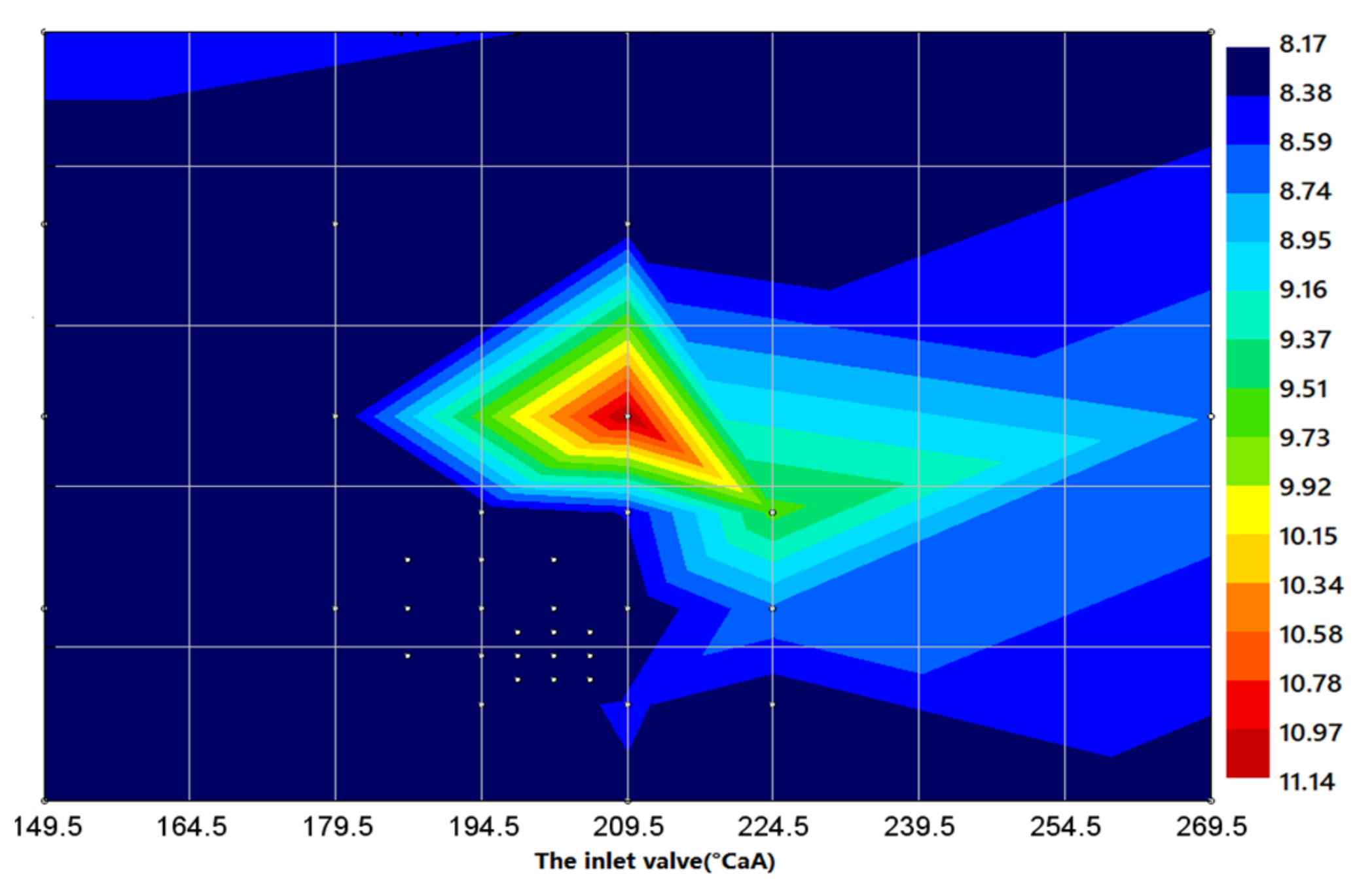
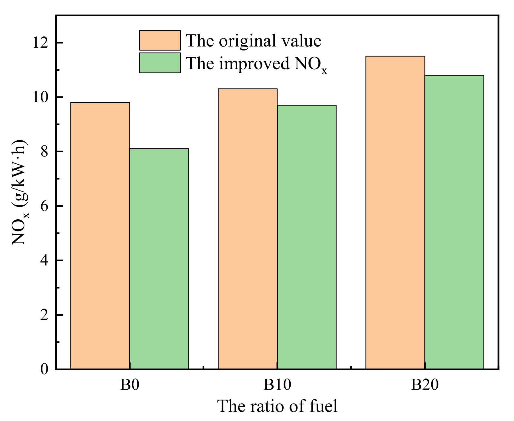
3.4. Optimization Analysis of 16V265H Diesel Engine

Figure 11 shows the optimal calculation results of NOx emission by 16V265H diesel engine burning B0 at 1000 rpm and 75% load.
Figure 11 shows the NOx emission optimization results of the 16V265H diesel engine burning B0 pure diesel at 1000 rpm and 75% load. It can be seen from the figure that when this diesel engine uses B0 pure diesel, the maximum NOx emission occurs near the intake valve timing of 209.5°CA. The lowest NOx emission area appears near the intake valve timing of 202°CA; the trends of other biodiesel ratios (B10, B20) are similar to those of B0.
Figure 12 shows the NOx emission optimization results of a 16V265H diesel engine fueled with different ratios of biodiesel under 1000 rpm and 75% load conditions. It can be seen from the figure that the NOx emission of the diesel engine after model optimization is lower than before optimization. The diesel engine has the lowest NOx emission when fueled by B0 pure diesel.
The Optimizer model is used to calculate the different ratios of biodiesel used by a 16V265H diesel engine at the speed of 1000 rpm and 75% load. It is concluded that the optimal scheme is as follows: B10 biodiesel fuel, intake valve timing near 202°CA, the exhaust valve timing near 98°CA; NOx emission of the diesel engine is the lowest. The effect of using B20 biodiesel is the second-best scheme. NOx emission of diesel engine is related to combustion temperature and oxygen content in the oil–gas mixture during combustion (i.e., high-temperature oxygen enrichment condition) [17,18]. The use of biodiesel makes the injection occur earlier and leads to an increase in NOx emission; therefore, the more biodiesel content, the more NOx emission.

3.5. Performance Comparison Based on Model Optimization

According to the optimization results of the various performance parameters of the 16V265H diesel engine by the Optimizer model, it is feasible to use low-ratio biodiesel in locomotive diesel engines. The initial valve timing bench test was compared with the optimized calculated value. The comparison indicators are BSFC and power, as shown in Table 5.
It can be seen from the table that when the diesel engine is optimized, its BSFC has been significantly reduced compared with the original engine, its power has been improved, and the trend of the range optimization effect is relatively consistent. Under 75% load condition, the BSFC reduction rate is up to 6.32% and the power increase rate is up to 5.87%. The diesel engine uses B10 biodiesel under 75% load conditions and has the best effect.

4. Conclusions

Currently, with the rapid developments in economy and industrial automation, the shortage of resources (such as non-renewable energy [49,50,51], oil [52], and coal [53]) and environmental pollution (air pollution [54,55,56,57] and human health [58]) are becoming more and more serious. How to effectively control energy shortages and reduce engine emissions are the main areas of interest for researchers today. In this paper, based on the simulation model of a 16V265H diesel engine built by GT-Power software, the Optimizer optimization model coupled with Simulink and GT-Power was used to study the parameters of diesel engine power, BSFC, and emission as the optimization objectives under different load conditions for diesel engines burning biodiesel with different ratios. The main conclusions obtained are as follows.
(1) The maximum power increase in this diesel engine when fueled with B0 at 75% load condition is 5.9%. The optimal solution for power under 75% load condition is obtained through the Optimizer model optimization: B10 biodiesel fuel, intake valve timing of 179.5°CA near the maximum power. This is because the intake air flow corresponding to the valve overlap angle within the valve timing range is large, the oil–gas mixture in the cylinder is sufficient, the combustion effect is good, and the power increases accordingly.
(2) The BSFC of the diesel engine under 75% load condition is reduced after optimization. Through the Optimizer model optimization, the optimal BSFC scheme under 75% load conditions is: use B10 biodiesel with the intake valve timing at 180°CA; this scheme has the lowest BSFC. The main reason is that the intake air corresponding to the valve overlap angle near the valve timing increases, resulting in full fuel blending, more complete combustion, and reduced fuel consumption.
(3) Based on the Optimizer model optimization, the soot emission of this diesel engine under 75% load conditions with different ratios of biodiesel decreases as the ratio increases, and the lowest carbon smoke emission is achieved when B20 biodiesel is used. From the optimization results, it can be seen that the optimal solution for the diesel engine to reduce soot emission under 75% load conditions with different ratios of biodiesel is: using B20 biodiesel with soot of the diesel engine near 264.5°CA at the intake valve timing, the emission is the lowest; the effect of using B10 biodiesel is the second optimal scheme.
(4) Based on the Optimizer model optimization, the diesel engine burning different ratios of biodiesel under 75% load condition shows an increasing trend of NOx emission with the increase in the ratio. With the increase in the injection advance angle and the extension of the ignition delay period, the amount of fuel injected into the cylinder in the premixing stage increases. A large amount of oil–gas mixture burns instantaneously in the premixing stage, releasing a large amount of heat; the temperature and pressure in the cylinder rise sharply, and the NOx emission increases. From the optimization results, it can be seen that the optimal solution for this diesel engine to use different ratios of biodiesel to reduce NOx emission at 75% load is: the intake valve timing is near 202°CA and B10 biodiesel is used.

Author Contributions

Conceptualization, F.J.; software, F.J., W.C.; formal analysis, F.J., J.H. and Z.T.; investigation, F.J., W.C., X.T., J.H., J.Z. and Z.T.; resources, F.J.; writing—original draft preparation, F.J., W.C., J.H.; writing—review and editing, F.J., W.C., X.T., J.H., J.Z. and Z.T.; supervision, F.J.; funding acquisition, F.J., X.T., J.H. All authors have read and agreed to the published version of the manuscript.

Funding

This research was funded by the Doctoral Fund Project of Guangxi University of Science and Technology, grant number 21Z34 and 21Z46.

Institutional Review Board Statement

Not applicable.

Data Availability Statement

All data used to support the findings of this study are included within the article.

Acknowledgments

This research was funded by the Doctoral Fund Project of Guangxi University of Science and Technology, grant number 21Z34 and 21Z46.

Conflicts of Interest

The authors declare that there is no conflict of interest regarding the publication of this paper.

Nomenclature

CA
CO
Crankshaft angle
Carbon monoxide
HCHydrocarbon
NOxNitrogen oxides
CO2Carbon dioxide
PMParticulate matter
CFDComputational fluid dynamics
NO2Nitrogen dioxide
NONitric oxide
BSFCBrake specific fuel consumption
BTEBrake thermal efficiency
NGNatural gas
RCCIReactivity controlled compression ignition
LCVLow calorific value
SOIStart of injection
ECUElectronic control unit
IVOIntake valve opening
IVCIntake valve closing
EVOExhaust valve opening
EVCExhaust valve closing
FAMEFatty acid methyl esters
SMESoybean oil methyl ester
B0100% diesel + 0% biodiesel
B1090% diesel + 10% biodiesel
B2080% diesel + 20% biodiesel

References

  1. Jiaqiang, E.; Zhang, Z.; Chen, J.; Pham, M.; Zhao, X.; Peng, Q.; Zhang, B.; Yin, Z. Performance and emission evaluation of a marine diesel engine fueled by water biodiesel-diesel emulsion blends with a fuel additive of a cerium oxide nanoparticle. Energy Convers. Manag. 2018, 169, 194–205. [Google Scholar] [CrossRef]
  2. Cai, T.; Zhao, D.; Wang, B.; Li, J.; Guan, Y. NO emission and thermal performances studies on premixed ammonia-oxygen combustion in a CO2-free micro-planar combustor. Fuel 2021, 280, 118554. [Google Scholar] [CrossRef]
  3. Peng, Q.; Xie, B.; Yang, W.; Tang, S.; Li, Z.; Zhou, P.; Luo, N. Effects of porosity and multilayers of porous medium on the hydrogen-fueled combustion and micro-thermophotovoltaic. Renew. Energy 2021, 174, 391–402. [Google Scholar] [CrossRef]
  4. Xie, B.; Peng, Q.; Yang, W.; Li, S.; E, J.; Li, Z.; Tao, M.; Zhang, A. Effect of pins and exit-step on thermal performance and energy efficiency of hydrogen-fueled combustion for micro-thermophotovoltaic. Energy 2022, 239, 122341. [Google Scholar] [CrossRef]
  5. Cai, T.; Zhao, D. Mitigating NOx emissions from an ammonia-fueled micro-power system with a perforated plate implemented. J. Hazard. Mater. 2021, 401, 123848. [Google Scholar] [CrossRef] [PubMed]
  6. Zhang, Z.; Ye, J.; Tan, D.; Feng, Z.; Luo, J.; Tan, Y.; Huang, Y. The effects of Fe2O3 based DOC and SCR catalyst on the combustion and emission characteristics of a diesel engine fueled with biodiesel. Fuel 2021, 290, 120039. [Google Scholar] [CrossRef]
  7. Tan, D.; Chen, Z.; Li, J.; Luo, J.; Yang, D.; Cui, S.; Zhang, Z. Effects of Swirl and Boiling Heat Transfer on the Performance Enhancement and Emission Reduction for a Medium Diesel Engine Fueled with Biodiesel. Processes 2021, 9, 568. [Google Scholar] [CrossRef]
  8. Fan, L.; Cheng, F.; Zhang, T.; Liu, G.; Yuan, J.; Mao, P. Visible-light photoredox-promoted desilylative allylation of a-silylamines: An efficient route to synthesis of homoallylic amines. Tetrahedron Lett. 2021, 81, 153357. [Google Scholar] [CrossRef]
  9. Cai, T.; Becker Sid, M.; Cao, F.; Bing Wang, B.; Tang, A.; Fu, J.; Han, L.; Sun, Y.; Zhao, D. NOx emission performance assessment on a perforated plate-implemented premixed ammonia-oxygen micro-combustion system. Chem. Eng. J. 2021, 417, 128033. [Google Scholar] [CrossRef]
  10. Zhang, Z.; E, J.; Chen, J.; Zhu, H.; Zhao, X.; Han, D.; Zuo, W.; Peng, Q.; Gong, J.; Yin, Z. Effects of low-level water addition on spray, combustion and emission characteristics of a medium speed diesel engine fueled with biodiesel fuel. Fuel 2019, 239, 245–262. [Google Scholar] [CrossRef]
  11. Poorghasemi, K.; Saray, R.; Ansari, E.; Irdmousa, B.; Shahbakhti, M.; Naber, J. Effect of diesel injection strategies on natural gas/diesel RCCI combustion characteristics in a light duty diesel engine. Appl. Energy 2017, 199, 430–446. [Google Scholar] [CrossRef]
  12. Zhang, Z.; Tian, J.; Li, J.; Ji, H.; Tan, D.; Luo, J.; Jiang, Y.; Yang, D.; Cui, S. Effects of Different Mixture Ratios of Methanol-Diesel on the Performance Enhancement and Emission Reduction for a Diesel Engine. Processes 2021, 9, 1366. [Google Scholar] [CrossRef]
  13. Yadav, J.; Ramesh, A. Injection strategies for reducing smoke and improving the performance of a butanol-diesel common rail dual fuel engine. Appl. Energy 2018, 212, 1–12. [Google Scholar] [CrossRef]
  14. Cai, T.; Zhao, D.; Sun, Y.; Ni, S.; Li, W.; Guan, D.; Wang, B. Evaluation of NOx emissions characteristics in a CO2-Free micro-power system by implementing a perforated plate. Renew. Sustain. Energy Rev. 2021, 145, 111150. [Google Scholar] [CrossRef]
  15. Delogu, M.; Del Pero, F.; Romoli, F.; Pierini, M. Life cycle assessment of a plastic air intake manifold. Int. J. Life Cycle Assess. 2015, 20, 1429–1443. [Google Scholar] [CrossRef] [Green Version]
  16. Diéguez, P.M.; Urroz, J.C.; Sáinz, D.; Machin, J.; Arana, M.; Gandía, L.M. Characterization of combustion anomalies in a hydrogen-fueled 1.4 L commercial spark-ignition engine by means of in-cylinder pressure, block-engine vibration, and acoustic measurements. Energy Convers. Manag. 2018, 172, 67–80. [Google Scholar] [CrossRef]
  17. Zhang, Z.; Ye, J.; Lv, J.; Xu, W.; Tan, D.; Jiang, F.; Huang, H. Investigation on the effects of non-uniform porosity catalyst on SCR characteristic based on the field synergy analysis. J. Environ. Chem. Eng. 2022, 10, 107056. [Google Scholar] [CrossRef]
  18. Zhang, Z.; Tian, J.; Xie, G.; Li, J.; Xu, W.; Jiang, F.; Huang, Y.; Tan, D. Investigation on the combustion and emission characteristics of diesel engine fueled with diesel/methanol/n-butanol blends. Fuel 2022, 314, 123088. [Google Scholar] [CrossRef]
  19. E, J.; Zhao, X.; Qiu, L.; Wei, K.; Zhang, Z.; Deng, Y.; Han, D.; Liu, G. Experimental investigation on performance and economy characteristics of a diesel engine with variable nozzle turbocharger and its application in urban bus. Energy Convers. Manag. 2019, 193, 149–161. [Google Scholar] [CrossRef]
  20. Ebrahimi, R. A new design method for maximizing the work output of cycles in reciprocating internal combustion engines. Energy Convers. Manag. 2018, 172, 164–172. [Google Scholar] [CrossRef]
  21. Polverino, P.; D’Aniello, F.; Arsie, I.; Pianese, C. Study of the energetic needs for the on-board production of Oxy-Hydrogen as fuel additive in internal combustion engines. Energy Convers. Manag. 2019, 179, 114–131. [Google Scholar] [CrossRef]
  22. Xu, Z.; Fu, J.; Liu, J.; Yuan, Z.; Shu, J.; Tan, L. Comparison of in-cylinder combustion and heat-work conversion processes of vehicle engine under transient and steady-state conditions. Energy Convers. Manag. 2017, 132, 400–409. [Google Scholar] [CrossRef]
  23. Wang, W.; Zuo, Z.; Liu, J. Miniaturization limitations of rotary internal combustion engines. Energy Convers. Manag. 2016, 112, 101–114. [Google Scholar] [CrossRef]
  24. Yang, X.; Liao, C.; Liu, J. Harmonic analysis and optimization of the intake system of a gasoline engine using GT-power. Energy Procedia 2012, 14, 756–762. [Google Scholar] [CrossRef] [Green Version]
  25. Qi, Y.; Dong, L.; Liu, H.; Puzinauskas, P.; Midkiff, K. Optimization of intake port design for SI engine. Int. J. Automot. Technol. 2012, 13, 861–872. [Google Scholar] [CrossRef]
  26. Pai, D.; Singh, H.S.; Muhammed, F. Simulation Based Approach for Optimization of Intake Manifold. SAE Tech. Pap. 2011. [Google Scholar] [CrossRef]
  27. Silva, E.; Ochoa, A.; Henriquez, J. Analysis and runners length optimization of the intake manifold of a 4-cylinder spark ignition engine. Energy Convers. Manag. 2019, 188, 310–320. [Google Scholar] [CrossRef]
  28. Zhang, Z.; E, J.; Chen, J.; Zhao, X.; Zhang, B.; Deng, Y.; Peng, Q.; Yin, Z. Effects of boiling heat transfer on the performance enhancement of a medium speed diesel engine fueled with diesel and rapeseed methyl ester. Appl. Therm. Eng. 2020, 169, 114984. [Google Scholar] [CrossRef]
  29. Leahu, C.-I. Improvement of exhaust gas pressure’s utilization for compressing the intake air in diesel engine’s cylinders. Int. J. Automot. Technol. 2015, 16, 913–921. [Google Scholar] [CrossRef]
  30. Wang, G.; Yu, W.; Li, X.; Yang, R. Influence of fuel injection and intake port on combustion characteristics of controllable intake swirl diesel engine. Fuel 2019, 262, 116548. [Google Scholar] [CrossRef]
  31. Ma, B.; Yao, A.; Yao, C.; Wu, T.; Wang, B.; Gao, J.; Chao, C. Exergy loss analysis on diesel methanol dual fuel engine under different operating parameters. Appl. Energy 2020, 261, 114483. [Google Scholar] [CrossRef]
  32. Kang, W.; Pyo, S.; Kim, H. Comparison of intake and exhaust throttling for diesel particulate filter active regeneration of non-road diesel engine with mechanical fuel injection pump. Int. J. Engine Res. 2020, 22, 146808742092603. [Google Scholar] [CrossRef]
  33. Cheng, L.; Dimitriou, P.; Weiji, W.; Peng, J.; Aitouche, A. A novel fuzzy logic variable geometry turbocharger and exhaust gas recirculation control scheme for optimizing the performance and emissions of a diesel engine. Int. J. Engine Res. 2018, 21, 1298–1313. [Google Scholar] [CrossRef]
  34. Li, Z.; Zhang, Y.; Huang, G.; Zhao, W.; He, Z.; Qian, Y.; Lu, X. Control of intake boundary conditions for enabling clean combustion in variable engine conditions under intelligent charge compression ignition (ICCI) mode. Appl. Energy 2020, 274, 115297. [Google Scholar] [CrossRef]
  35. Song, K.; Upadhyay, D.; Xie, H. An assessment of the impacts of low-pressure exhaust gas recirculation on the air path of a diesel engine equipped with electrically assisted turbochargers. Int. J. Engine Res. 2019, 22, 1–19. [Google Scholar] [CrossRef]
  36. Zhen, X.; Li, X.; Wang, Y.; Liu, D.; Tian, Z.; Wang, Y. Effects of the initial flame kernel radius and EGR rate on the performance, combustion and emission of high-compression spark-ignition methanol engine. Fuel 2019, 262, 116633. [Google Scholar] [CrossRef]
  37. Arnau, F.; Martín, J.; Pla, B.; Auñón, Á. Diesel engine optimization and exhaust thermal management by means of variable valve train strategies. Int. J. Engine Res. 2020, 22, 146808741989480. [Google Scholar] [CrossRef]
  38. E, J.; Zhiqing, Z.; Tu, Z.; Wei, Z.; Hu, W.; Han, D.; Jin, Y. Effect analysis on flow and boiling heat transfer performance of cooling water-jacket of bearing in the gasoline engine turbocharger. Appl. Therm. Eng. 2018, 130, 754–766. [Google Scholar] [CrossRef]
  39. Zhang, Z.; E, J.; Deng, Y.; Pham, M.; Zuo, W.; Peng, Q.; Yin, Z. Effects of fatty acid methyl esters proportion on combustion and emission characteristics of a biodiesel fueled marine diesel engine. Energy Convers. Manag. 2018, 159, 244–253. [Google Scholar] [CrossRef]
  40. Xia, M.; Zhang, F. Application of Multi-Parameter Fuzzy Optimization to Enhance Performance of a Regulated Two-Stage Turbocharged Diesel Engine Operating at High Altitude. Energies 2020, 13, 4278. [Google Scholar] [CrossRef]
  41. Huang, R.; Dai, Y.; Luo, X.; Wang, Y.; Huang, C. Multi-objective optimization of the flush-type intake duct for a waterjet propulsion system. Ocean Eng. 2019, 187, 106172. [Google Scholar] [CrossRef]
  42. Zhang, Z.; Li, J.; Tian, J.; Xie, G.; Tan, D.; Qin, B.; Huang, Y.; Cui, S. Effects of Different Diesel-Ethanol Dual Fuel Ratio on Performance and Emission Characteristics of Diesel Engine. Processes 2021, 9, 1135. [Google Scholar] [CrossRef]
  43. Shang, Z.; Yu, X.; Shi, W.; Huang, S.; Li, G.; Guo, Z.; He, F. Numerical research on effect of hydrogen blending fractions on idling performance of an n-butanol ignition engine with hydrogen direct injection. Fuel 2019, 258, 116082. [Google Scholar] [CrossRef]
  44. Jiang, F.; Li, M.; Wen, J.; Tan, Z.; Zhou, W. Optimization Analysis of Engine Intake System Based on Coupling Matlab-Simulink with GT-Power. Math. Probl. Eng. 2021, 2021, 6673612. [Google Scholar] [CrossRef]
  45. Bancalari, E.; Diakunchak, I.; McQuiggan, G. A Review of W501G Engine Design, Development and Field Operating Experience. ASME Pap. 2003, GT2003-38956, 963–969. [Google Scholar] [CrossRef]
  46. Fahd, M.E.A.; Wenming, Y.; Lee, P.S.; Chou, S.K.; Yap, C.R. Experimental investigation of the performance and emission characteristics of direct injection diesel engine by water emulsion diesel under varying engine load condition. Appl. Energy 2013, 102, 1042–1049. [Google Scholar] [CrossRef]
  47. Liu, T.; E, J.; Yang, W.; Hui, A.; Cai, H. Development of a skeletal mechanism for biodiesel blend surrogates with varying fatty acid methyl esters proportion. Appl. Energy 2016, 162, 278–288. [Google Scholar] [CrossRef]
  48. E, J.; Liu, T.; Yang, W.M.; Deng, Y.; Gong, J. A skeletal mechanism modeling on soot emission characteristics for biodiesel surrogates with varying fatty acid methyl esters proportion. Appl. Energy 2016, 181, 322–331. [Google Scholar] [CrossRef]
  49. Zuo, H.; Tan, J.; Wei, K.; Huang, Z.; Zhong, D.; Xie, F. Effects of different poses and wind speeds on wind-induced vibration characteristics of a dish solar concentrator system. Renew. Energy 2021, 168, 1308–1326. [Google Scholar] [CrossRef]
  50. Zuo, H.; Liu, G.; E, J.; Zuo, W.; Wei, K.; Hu, W.; Tan, J.; Zhong, D. Catastrophic analysis on the stability of a large dish solar thermal power generation system with wind-induced vibration. Sol. Energy 2019, 183, 40–49. [Google Scholar] [CrossRef]
  51. Zuo, H.; Zhang, B.; Huang, Z.; Wei, K.; Tan, J. Effect analysis on SOC values of the power lithium manganate battery during discharging process and its intelligent estimation. Energy 2022, 238, 121854. [Google Scholar] [CrossRef]
  52. Xie, Y.; Zuo, Q.; Zhu, G.; Guan, Q.; Wei, K.; Zhang, B.; Tang, Y.; Shen, Z. Investigations on the soot combustion performance enhancement of an improved catalytic gasoline particulate filter regeneration system under different electric heating powers. Fuel 2021, 283, 119301. [Google Scholar] [CrossRef]
  53. Chen, J.; Wang, Q.; Xu, Z.; E, J.; Leng, E.; Zhang, F.; Liao, G. Process in supercritical water gasification of coal: A review of fundamentals, mechanisms, catalysts and element transformation. Energy Convers. Manag. 2021, 237, 114122. [Google Scholar] [CrossRef]
  54. Muhssen, H.S.; Masuri, S.U.; Bin Sahari, B.; Hairuddin, A.A. Design improvement of compressed natural gas (CNG)-Air mixer for diesel dual-fuel engines using computational fluid dynamics. Energy 2021, 216, 118957. [Google Scholar] [CrossRef]
  55. Ning, L.; Duan, Q.; Zhanming, C.; Kou, H.; Liu, B.; Yang, B.; Zeng, K. A comparative study on the combustion and emissions of a non-road common rail diesel engine fueled with primary alcohol fuels (methanol, ethanol, and n-butanol)/diesel dual fuel. Fuel 2020, 266, 117034. [Google Scholar] [CrossRef]
  56. E, J.; Liu, G.; Zhang, Z.; Han, D.; Chen, J.; Wei, K.; Gong, J.; Yin, Z. Effect analysis on cold starting performance enhancement of a diesel engine fueled with biodiesel fuel based on an improved thermodynamic model. Appl. Energy 2019, 243, 321–335. [Google Scholar] [CrossRef]
  57. Chen, L.; Deng, Y.; Feng, C.; Han, W.; E, J.; Wang, C.; Han, D.; Zhang, B. Effects of zeolite molecular sieve on the hydrocarbon adsorbent performance of gasoline engine of during cold start. Fuel 2022, 310, 122427. [Google Scholar] [CrossRef]
  58. E, J.; Luo, J.; Han, D.; Tan, Y.; Feng, C.; Deng, Y. Effects of different catalysts on light-off temperature of volatile organic components in the rotary diesel particulate filter during the regeneration. Fuel 2022, 310, 122451. [Google Scholar] [CrossRef]
Figure 1. Schematic diagram of one-dimensional search method.
Processes 10 00157 g001
Figure 2. Optimizer model.
Processes 10 00157 g002
Figure 3. Picture of diesel engine bench test.
Processes 10 00157 g003
Figure 4. Simulation model of the entire diesel engine.
Processes 10 00157 g004
Figure 5. (a) B0, (b) B10, and (c) B20. Power of different biodiesel ratios under 75% load condition.
Processes 10 00157 g005
Figure 6. Comparison between the improved power and the original value under 75% load.
Processes 10 00157 g006
Figure 7. (a) B0, (b) B10, (c) B20. BSFC of different biodiesel ratios under 75% load condition.
Processes 10 00157 g007
Figure 8. Comparison between the improved BSFC and the original value under 75% load.
Processes 10 00157 g008
Figure 9. (a) B0 and (b) B20. Soot emission of different biodiesel ratios under 75% load condition.
Processes 10 00157 g009
Figure 10. Comparison between the improved soot and the original value under 75% load.
Processes 10 00157 g010
Figure 11. NOx emission of B0 under 75% load condition.
Processes 10 00157 g011
Figure 12. Comparison between the improved NOx and the original value under 75% load.
Processes 10 00157 g012
Table 1. Main instruments and test standards.
Physical and Chemical ParametersTest InstrumentTest StandardAccuracy
Kinetic viscosity (mm2/s) (at 40 °C)SYD-265HGB/T265±0.05%
Density (g/cm3)KD-R1022ADTM D445±0.1%
Calorific value (MJ/kg)MTZW-A4ASTM D240±0.1%
Surface tension (mN/m)JYW-200GB/T6541-86≤±1%FS
Table 2. Physical properties of FAMEs present.
TypeKinetic Viscosity (mm2/s) (at 40 °C)Density (g/cm3)Molecular Weight (g/mol)Higher Calorific Value (MJ/kg)SME Composition % Volume
C18:33.110.89929239.438.11
C18:23.790.88729439.6822.27
C18:14.600.87529639.9365.18
C18:05.590.86329840.180.87
C16:04.370.86427039.563.57
Table 3. The properties of biodiesel with different ratios.
TypeB0B10B20
Density (20 °C)/(kg·m−3)836.3842.2850.1
Sulfur content (mass fraction)/%0.02340.01870.0143
Acidity/(mgKOH/100 mL)4.493.034.19
Copper corrosion (50 °C, 3 h)/grade≤1≤1≤1
Kinematic viscosity (20 °C)/(mm2·s−1)4.5788.0578.627
Flash point (closed) (°C)637474
Cold filter point (°C)−422
Condensation point (°C)−7−6−5
Boiling point (°C)180~370142145
Heptadecane index54.853.552.1
Table 4. The major technique parameters of the 16V265H diesel engine.
Model16V265H
TypeFour stroke, direct injection, exhaust gas turbocharging, supercharging, and intercooling
Number of cylinders and V-angle16 cylinders, 45°
Bore × stroke265 × 300 mm
Total displacement264.74 L
Compression ratio15.4
Calibration power4660 kW
Calibration speed1000 rpm
Minimum idle stable speed325 rpm
Minimum working stable speed400 rpm
Average piston speed10 m/s
Firing sequence Processes 10 00157 i001
Start modeAir motor start
Crankshaft steeringFacing the output, counterclockwise
Overall dimensions: long × wide × high5890 × 1780 × 2760 mm
Table 5. The performance comparison before and after biodiesel optimization.
Oil Consumption (g/(kW·h))Power (kW)
Original Machine Test ValueOptimize Simulation ValueDegree of DecliningOriginal Machine Test ValueOptimize Simulation ValueImprove the Range
B0201.2188.486.32%375139715.86%
B10205.18192.26.32%369139085.87%
B20208.77195.576.31%363138445.86%
Publisher’s Note: MDPI stays neutral with regard to jurisdictional claims in published maps and institutional affiliations.

