Article

Enhancing Q-Factor in a Biquadratic Bandpass Filter Implemented with Opamps

by
Esteban Tlelo-Coyotecatl
1,
Alejandro Díaz-Sánchez
2,
José Miguel Rocha-Pérez
2,
Jose Luis Vázquez-González
1,
Luis Abraham Sánchez-Gaspariano
3 and
Esteban Tlelo-Cuautle
2,*
1
School of Engineering, Universidad de las Américas Puebla, 72810 San Andrés Cholula, Mexico
2
Department of Electronics, National Institute for Astrophysics, Optics, and Electronics, 72840 Puebla, Mexico
3
Faculty of Electronics Science, Benemérita Universidad Autónoma de Puebla, 72000 Puebla, Mexico
*
Author to whom correspondence should be addressed.
Technologies 2019, 7(3), 64; https://doi.org/10.3390/technologies7030064
Submission received: 14 August 2019 / Revised: 1 September 2019 / Accepted: 2 September 2019 / Published: 11 September 2019

Abstract

:
Active filter design is a mature topic that provides good solutions that can be implemented using discrete devices or integrated circuit technology. For instance, when the filter topologies are implemented using commercially available operational amplifiers (opamps), one can explore varying circuit parameters to tune the central frequency or enhance the quality (Q) factor. We show the addition of a feedback loop in the signal flow graph of a biquadratic filter topology, which enhances Q and highlights that a sensitivity analysis can be performed to identify which circuit elements influence central frequency, Q, or both. In this manner, we show the opamp-based implementation of a biquadratic bandpass filter, in which Q is enhanced through performing a sensitivity analysis for each circuit element. Equations for the central frequency and Q are provided to observe that there is not a direct parameter that enhances them, but we show that from sensitivity analysis one can identify the circuit elements that better enhance Q-factor.

1. Introduction

The book by P. E. Allen and L. P. Huelsman is a classic active filter design reference [1] that helps us understand how to implement different filter topologies using operational amplifiers (opamps). Among the currently available active filter topologies, the most known opamp-based implementations are the opamp-RC filters, which have been widely used in many low-frequency applications, telecommunication networks, signal processing and conditioning circuits, communication systems, control, and instrumentation. In modern applications, active filters with low-noise level and stable, high-quality Q-factor are strictly desirable for processing weak signals. Several problems remain open as for example the necessity of designing a low-frequency opamp-RC filter that can find applications to detect, measure, and quantify biomedical signals or object vibrations, among others. This design issue has the problem of using large capacitor values to implement large RC time constants, so that other alternatives are proposed to design active filters using integrated circuit technology. For example, the authors of [2] introduced a bandpass filter (BPF) with independent bandwidth and center frequency adjustment, and provide simulations using 180 nm CMOS technology. The complex BPF is designed employing positive feedback technique to control bandwidth at different center frequencies. Contrary to the BPF, other authors focused on bandstop filters to design controllers for space shuttle vehicles, and the filter structure can be designed using low-pass and high-pass filters, as shown in the work by the authors of [3]. Reconfigurability is another issue that has been introduced very recently in the work by the authors of [4], accompanied by a reduction in power and sensitivity to circuit nonidealities for a bandpass modulator applied in a digital intermediate frequency receiver system.
Bandpass active filters find a wide range of applications, for example, a compact dual-band BPF with multiple transmission zeros and wide stopband is introduced in the work by the authors of [5]; a dual-mode tunable BPF for global system for mobile communication, universal mobile telecommunications system, wireless fidelity, and worldwide interoperability for microwave access standard applications is given in the work by the authors of [6]; a power-efficient, highly linear, front-end integrated circuit for electrocardiogram acquisition applications that uses only one bandpass instrumentation amplifier is proposed in the work by the authors of [7]; a programmable second-order bandpass switched-capacitor filter implemented for an Internet-of-Things water management sensor node is given in the work by the authors of [8]; and so on. More recently, researchers are dealing with Gm-C filter topologies, which require operational transconductance amplifiers such as the fifth-order continuous-time Gm-C-based quadrature bandpass sigma-delta modulator for Internet-of-Things applications that is presented in the work by the authors of [9]. Fortunately, if one designs an opamp-RC filter with stable and high Q factor, such a topology can be transformed to a Gm-C one that can work in voltage-mode or current-mode, as shown in the work by the authors of [10]. For instance, some recent efforts on designing BPF responses work in current-mode, like in works by the authors of [11,12]; in voltage-mode, like in works by the authors of [13,14]; or apply modern active devices, like in works by the authors of [15,16,17]. Also, other efforts are oriented to provide reconfigurability and tune-ability at the same time and designing fractional-order circuits as in the work by the authors of [18]. In all these recent works, enhancing Q is one of the main design objectives.
This article presents a biquadratic BPF topology that is analyzed applying signal flow graphs and implemented with opamps, resistors, and capacitors. A modified version is introduced herein that includes one extra feedback loop in the signal flow graph to enhance Q. In the opamp-RC topology, the capacitor values are fixed and a sensitivity analysis is performed for each resistance to identify which one can help to enhance the Q factor, which must be as high as possible to avoid energy loss. Some recent works on enhancing the Q factor in a bandpass filter include works by the authors of [19,20]. In the former work, the authors propose a modified charge-sharing bandpass filter with cross-connected transconductors to boost Q-factor, and, in the other work, a tunable synthetic fourth-order bandpass filter is synthesized by two parallel second-order Q-enhanced LC bandpass filters. Neither work shows the sensitivity effect of all the circuit elements and parameters, but the Q factor is enhanced. The following sections will describe the bandpass filter topology to enhance Q, its symbolic analysis, and its realization to highlight that the Q factor is enhanced from identifying sensitive circuit elements.

2. Simulation and Signal Flow Graph Analysis

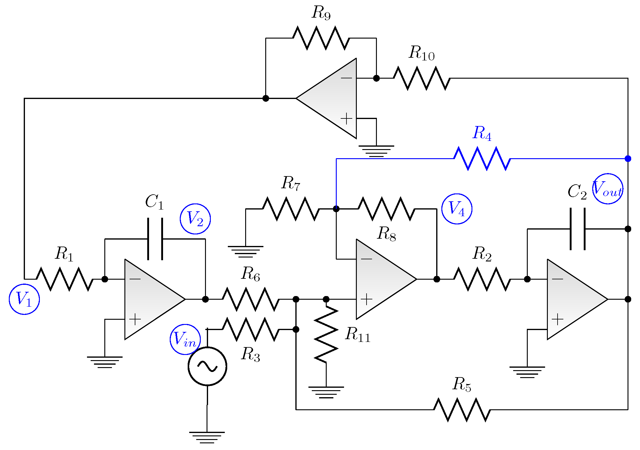
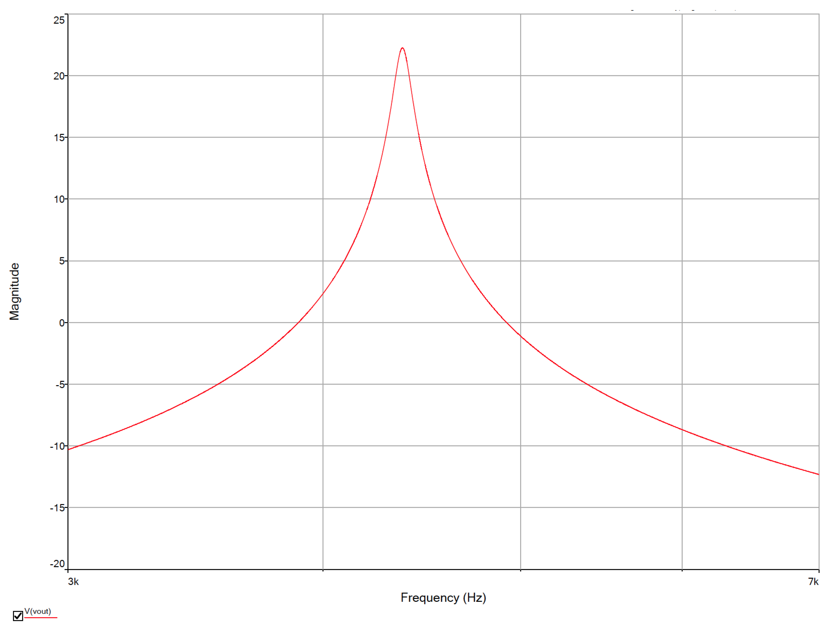
The case of study is the opamp-RC BPF shown in Figure 1. This BPF has an associated signal flow graph shown on the left side in Figure 2. The augmentation of one feedback loop, labeled K 1 , from node V o u t to V 4 is shown on the right side in Figure 2, and it is implemented by adding just one resistor R 4 to Figure 1 in order to get the opamp-RC topology shown in Figure 3. This is a biquadratic BPF that is implemented using four opamps, eleven resistances, and two capacitors. The simulation of this BPF is done using models of the commercially available opamp LM741, and the circuit element values are set to R 1 = R 2 = R 5 = 10 k Ω , R 3 = R 6 = R 11 = 20 k Ω , R 4 = 53.41 k Ω , R 7 = 53.09 k Ω , R 8 = 60.3 k Ω , R 9 = 11.66 k Ω , R 10 = 1 k Ω , and C 1 = C 2 = 10 nF. The frequency response is shown in Figure 4.
From the frequency simulation, one can evaluate the Q-factor by using the expression in Equation (1), which requires the evaluation of the central frequency f o over the bandwidth of the passband, which is calculated by subtracting the high frequency f H minus the low frequency f L , which are measured three decibels (−3 dB) below f o . From the frequency response shown in Figure 4, the corresponding values to evaluate Q are f 0 , located at 4.3760 kHz with a magnitude of 22.27 dB; f L = 4.2248 kHz; and f H = 4.4176 kHz. So that Q = 22.697.
Q = f 0 f H f L
To enhance the Q factor, the most appropriate circuit elements to update must be found, so that deriving the expressions for frequency and Q may help. Therefore, evaluating V 4 from the signal flow graph shown on the right side in Figure 2, one gets (2). Using the signal flow graph and the topology shown in Figure 3, the other voltage nodes are given in Equations (3)–(5). In those cases, the values of K 1 K 5 are given by Equations (6)–(10), respectively.
V 4 = V o u t R 8 R 4 + V i n ( 1 + R 8 R 4 | | R 7 ) ( R 5 | | R 6 | | R 11 R 5 | | R 6 | | R 11 + R 3 ) + V 2 ( 1 + R 8 R 4 | | R 7 ) ( R 3 | | R 5 | | R 11 R 3 | | R 5 | | R 11 + R 6 ) + V o u t ( 1 + R 8 R 4 | | R 7 ) ( R 3 | | R 6 | | R 11 R 3 | | R 6 | | R 11 + R 5 )
V 1 = V o u t R 9 R 10
V 2 = V 1 s C 1 R 1
V o u t = V 4 s C 2 R 2
K 1 = R 8 R 4
K 2 = ( 1 + R 8 R 4 | | R 7 ) ( R 5 | | R 6 | | R 11 R 5 | | R 6 | | R 11 + R 3 )
K 3 = ( 1 + R 8 R 4 | | R 7 ) ( R 3 | | R 5 | | R 11 R 3 | | R 5 | | R 11 + R 6 )
K 4 = R 9 R 10
K 5 = ( 1 + R 8 R 4 | | R 7 ) ( R 3 | | R 6 | | R 11 R 3 | | R 6 | | R 11 + R 5 )
In this manner, Equation (2) can be updated to (11), and then the symbolic transfer function can be expressed by Equation (12), from which one can evaluate the angular frequency ω o and Q, as given by Equations (13) and (14).
V o u t s C 2 R 2 = V o u t K 1 + V i n K 2 + V o u t K 2 K 4 s C 1 R 1 + V o u t K 5
V o u t V i n = s K 2 C 2 R 2 s 2 + s K 5 K 1 C 2 R 2 + K 2 K 4 C 1 R 1 C 2 R 2
ω o = K 2 K 4 C 1 R 1 C 2 R 2
Q = C 2 R 2 K 5 K 1 K 2 K 4 C 1 R 1 C 2 R 2

3. Sensitivity Analysis Performed in NI Multisim

Sensitivity analysis is not a trivial task for very large scale integration (VLSI) systems [21] because the accepted definition states that circuit sensitivity can be evaluated, considering the influence of a change in a particular circuit component on a circuit characteristic varies the value. Sensitivity analysis gives us an insight on how certain parameters influence in the response of a specific circuit. Therefore, the relative sensitivity (for a linearized model) for parameter W is given by the following equation:
S e n s ( H ( s ) , W ) = W H ( s ) H ( s ) W
In contrast, the unnormalized or absolute sensitivity is simply the partial derivative H ( s ) W . The authors of [21] provide guidelines to evaluate sensitivities in VLSI systems. This can be done replacing the transfer function H ( s ) by its polynomials in the numerator N ( s ) and denominator D ( s ) , leading to the expression given in Equation (16), from which after regrouping similar terms one gets to the expression in (17), which is suitable for VLSI systems.
S e n s H ( s ) , W = W D ( s ) N ( s ) N ( s ) W D ( s ) N ( s ) D ( s ) W D 2 ( s )
S e n s ( H ( s ) , W ) = W 1 N ( s ) N ( s ) W 1 D ( s ) D ( s ) W
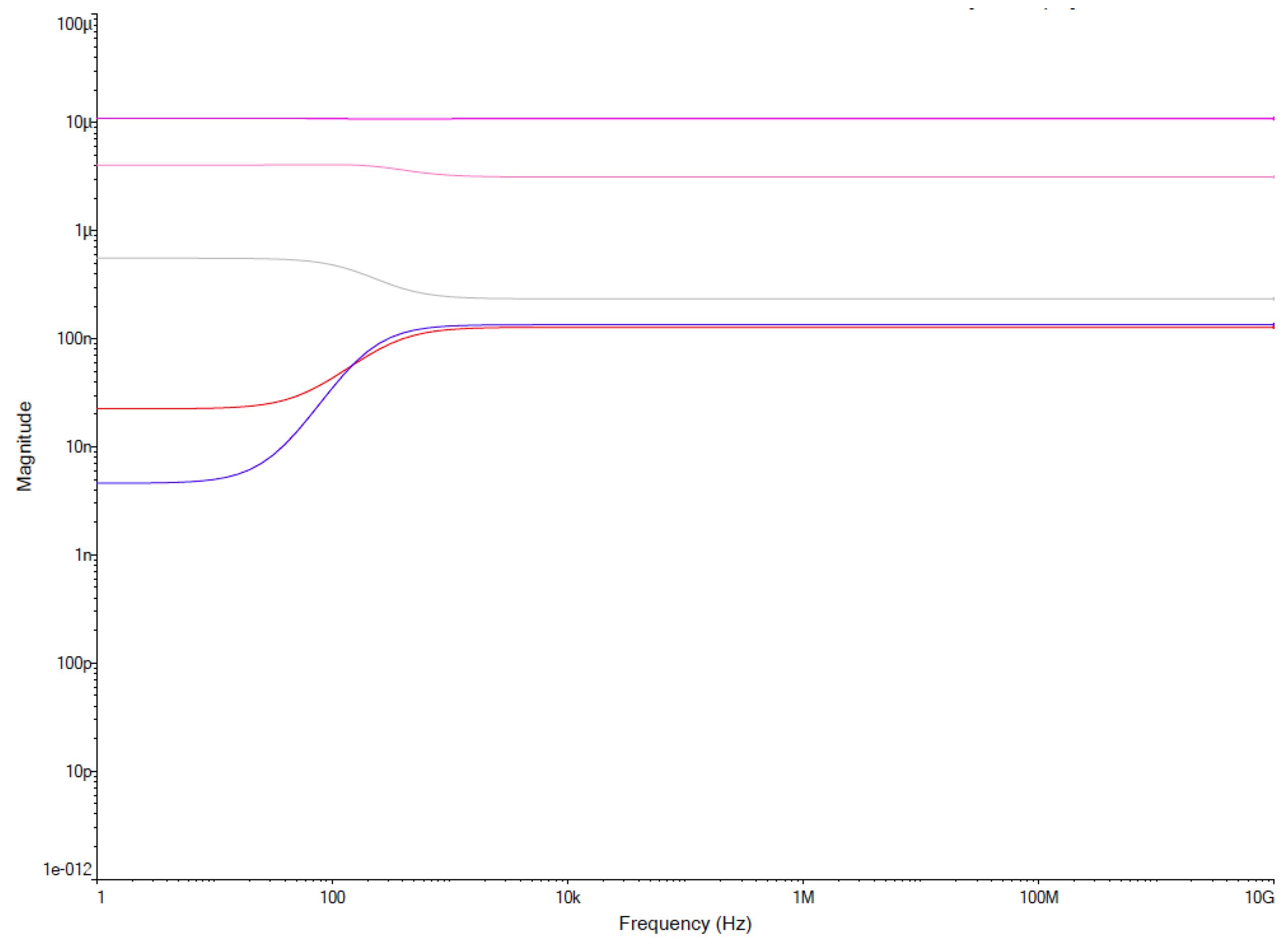
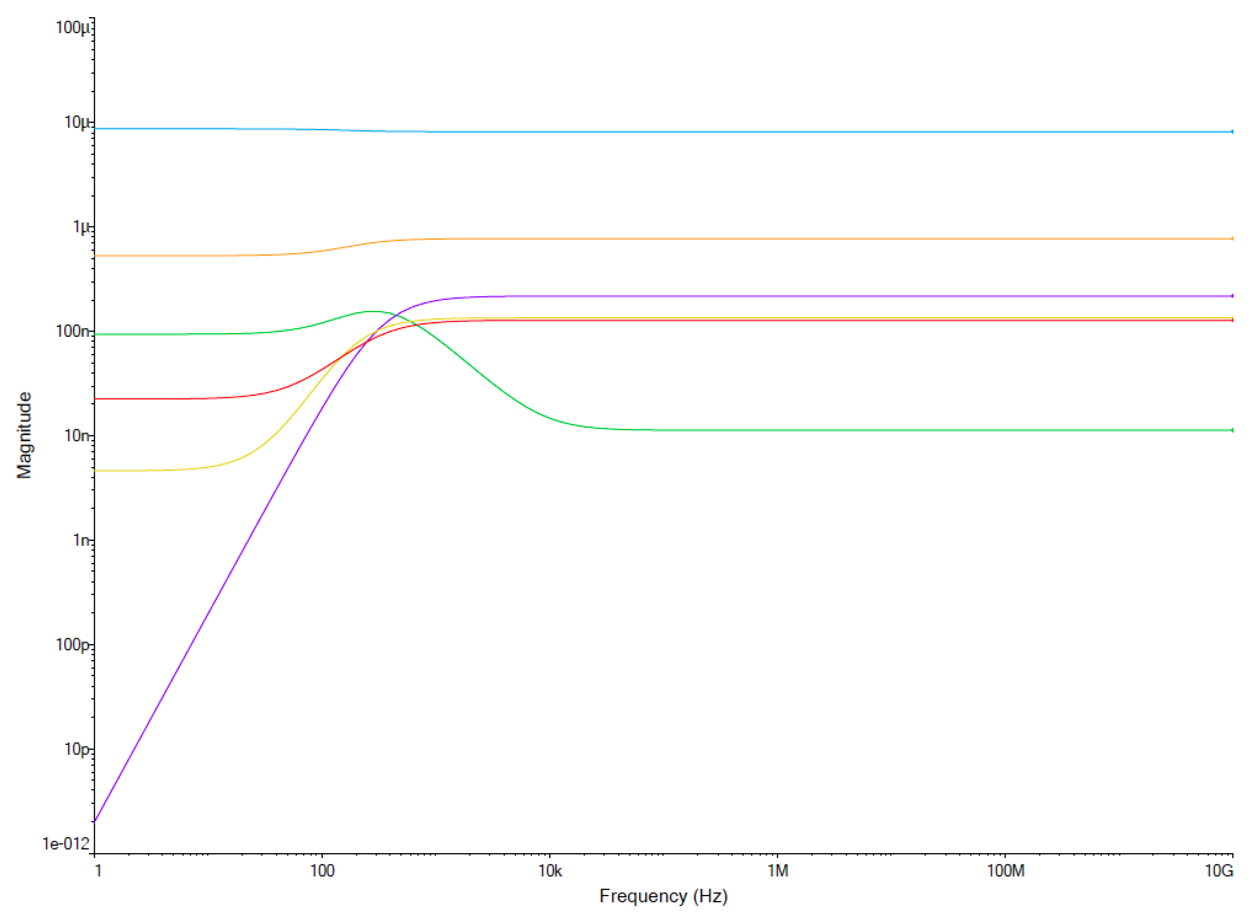
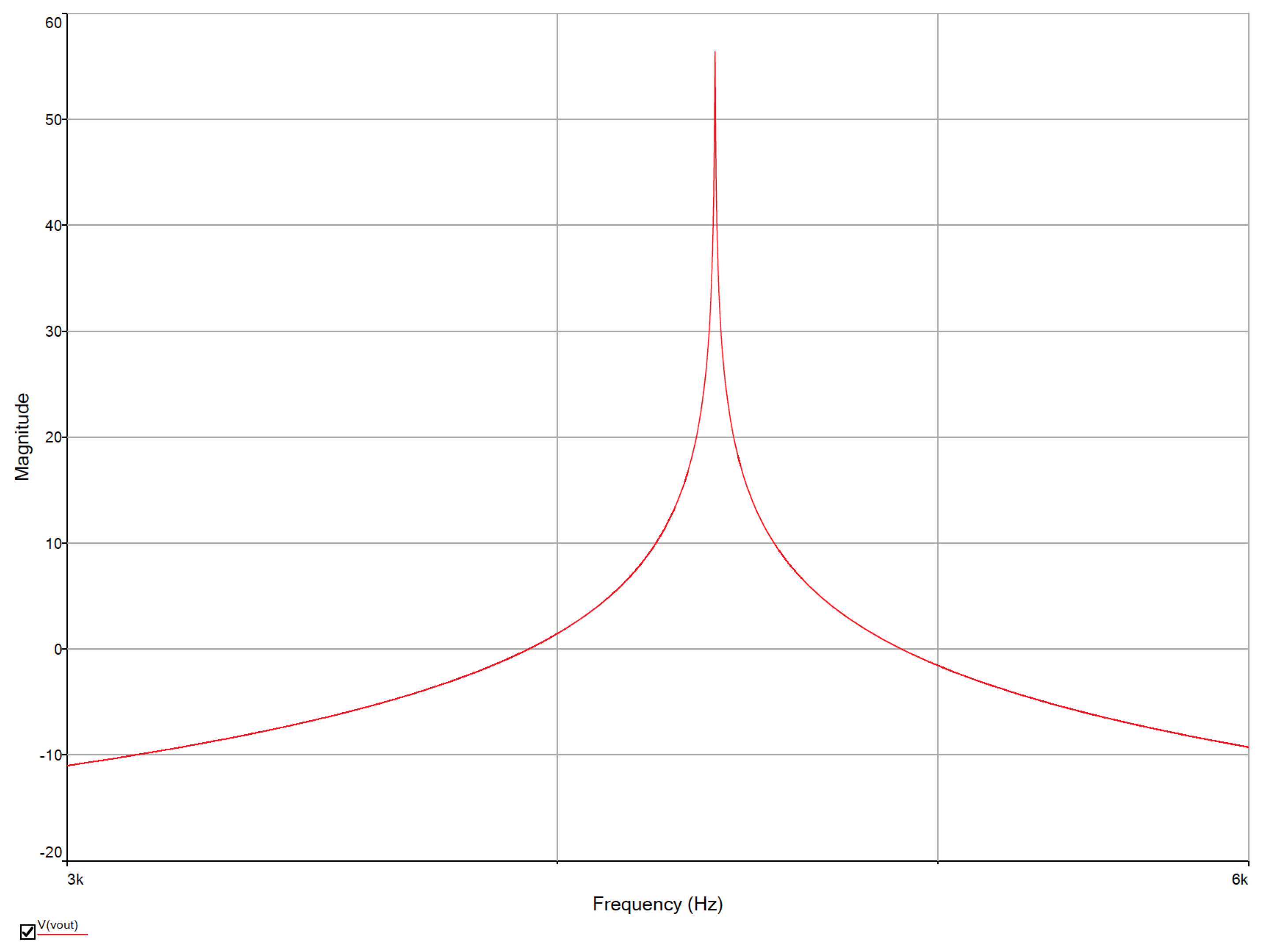
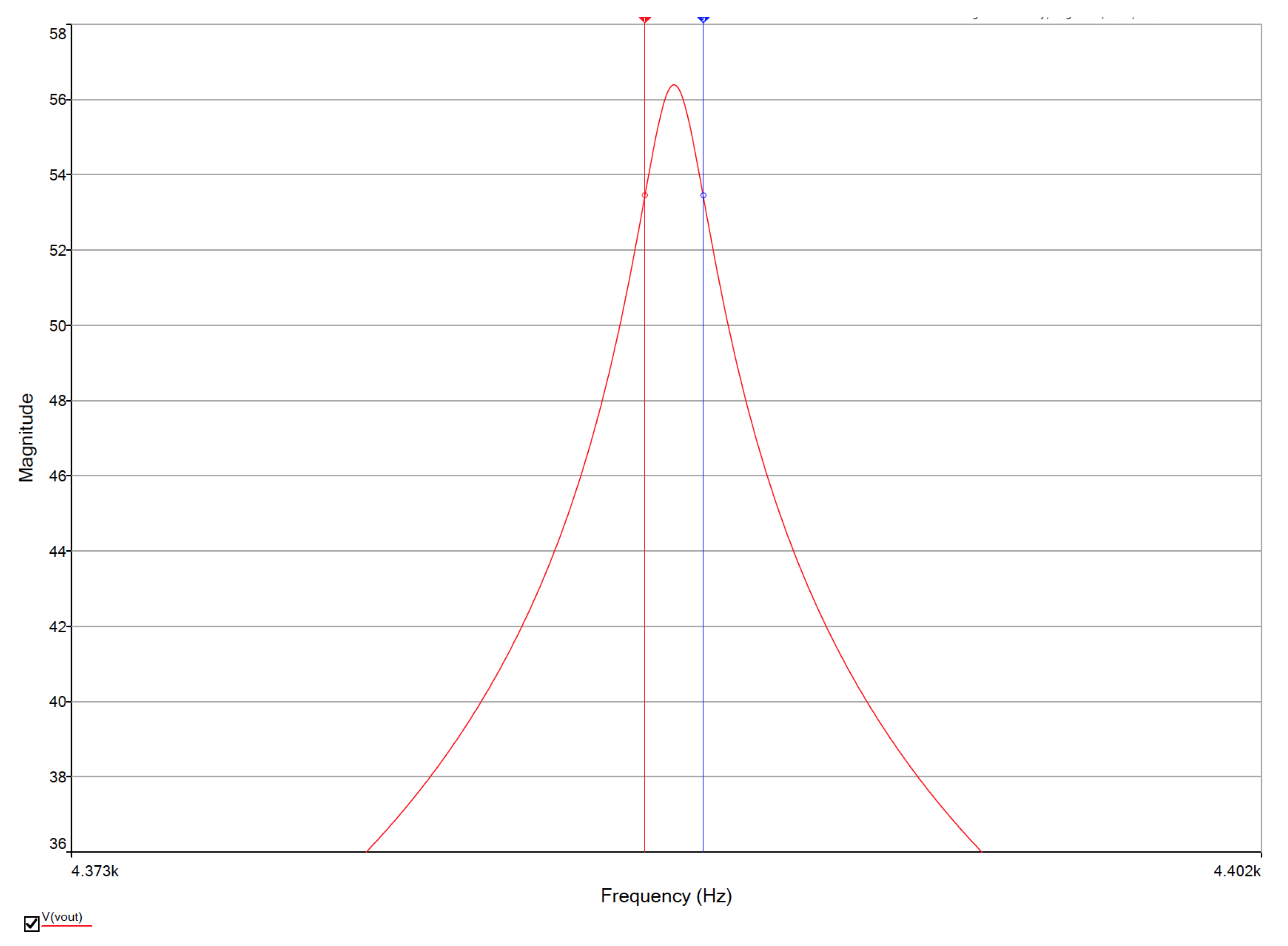
In the case of opamp-RC filters, such as the one shown in Figure 3, one can perform numerical simulations using circuit simulators like NI multisim. In this way, the sensitivity analysis was performed for the eleven resistances leading to the results shown in Figure 5 and Figure 6. From these results, the resistances generating high sensitivities were varied in a range between 10% and 20%, thus enhancing the Q factor. The resistances R 1 , R 3 , and R 10 provided high sensitivity, and they were varied to enhance Q, as shown in Figure 7. In this case, the updated values of the resistors for the simulation were adjusted to become R 1 = 8 k Ω , R 2 = R 5 = 10 k Ω , R 3 = 22 k Ω , R 4 = 53.41 k Ω , R 6 = R 11 = 20 k Ω , R 7 = 53.09 k Ω , R 8 = 60.3 k Ω , R 9 = 11.66 k Ω , and R 10 = 1.2 k Ω . The corresponding values in evaluating Equation (1) from Figure 8 are f 0 = 4.3801 kHz with a magnitude of 55.9295 dB, f L = 4.3794 kHz, and f H = 4.3809 kHz, leading to Q = 2920.06, which overpasses the Q value evaluated from Figure 4.
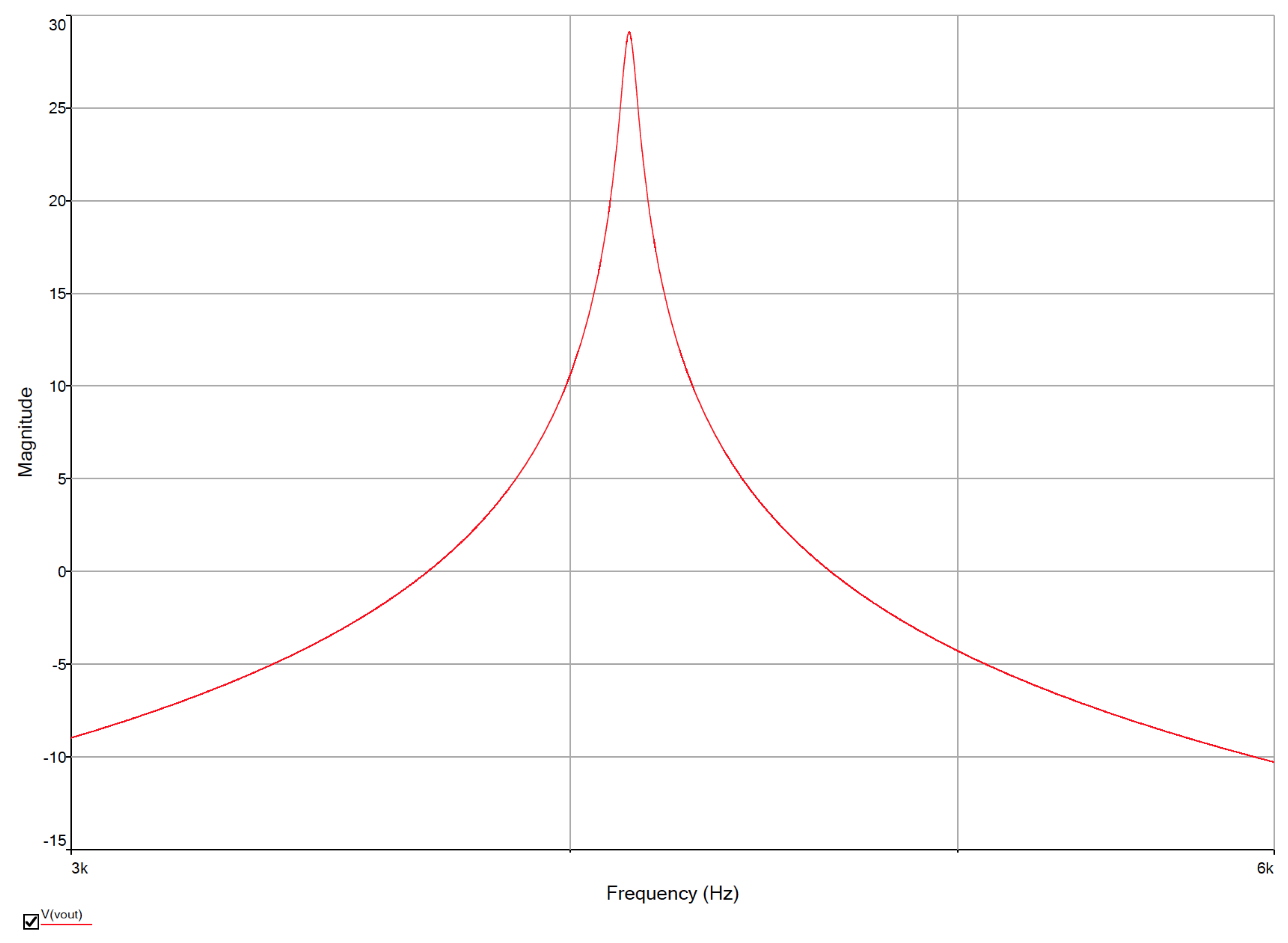
Designing filters with extremely high Q values may lead to circuit oscillation. In this manner, to have Q = 122.79, the following values were calculated; R 1 = 9 k Ω , R 2 = R 5 = 10 k Ω , R 3 = 22 k Ω , R 4 = 53 k Ω , R 6 = R 11 = 20 k Ω , R 7 = 53 k Ω , R 8 = 60.3 k Ω , R 9 = 11 k Ω , and R 10 = 1.2 k Ω . In this case, the frequency response is shown in Figure 9, where f 0 = 4.1381 kHz with magnitude of 29.0988 dB, f L = 4.1211 kHz with magnitude of 26.0993 dB, and f H = 4.1548 kHz with magnitude of 26.0998 dB. Replacing these values in Equation (1), Q = 122.79. In the same way, replacing the values of the resistances and capacitances in the transfer function, it becomes Equation (18), which produces the poles listed in Table 1. In this Table the three cases are given for the three Q that have different values of the resistors. It can be appreciated that the poles in the three cases are quite similar, but the Q value has a big difference ranging from 22.697 to 2920.06, as detailed in the whole manuscript.
V o u t V i n = 653 , 000 , 000 s s 2 + 326 , 500 , 000 s + 76.14 × 10 12

4. Conclusions

It has been highlighted that performing symbolic analysis in biquadratic filters helps enhance characteristics like the Q-factor. In this manner, we showed the addition of one feedback loop to a signal flow graph to enhance Q-factor of a BPF, which was implemented as an opamp-RC topology. Further, the Q-factor was enhanced by varying the resistances that were identified to have high sensitivities. The Q-factor was enhanced from 22.697 to 2920.06, for which the poles for each case were listed in Table 1, where it is appreciated that they are quite similar. This justifies the application of sensitivity analysis to identify those circuit elements that help to enhance desired characteristics as the Q-factor for active filters, like the bandpass filter implemented with opamps herein.

Author Contributions

Investigation: E.T.-C. (Esteban Tlelo-Coyotecatl), A.D.-S., J.M.R.-P., J.L.V.-G., L.A.S.-G., and E.T.-C. (Esteban Tlelo-Cuautle); Methodology: E.T.-C. (Esteban Tlelo-Coyotecatl), A.D.-S., and J.M.R.-P.; Writing—original draft: E.T.-C. (Esteban Tlelo-Coyotecatl), A.D.-S., J.M.R.-P., J.L.V.-G., and L.A.S.-G.; Writing—review and editing: E.T.-C. (Esteban Tlelo-Coyotecatl) and E.T.-C. (Esteban Tlelo-Cuautle).

Funding

This research received no external funding.

Conflicts of Interest

The authors declare no conflicts of interest.

References

  1. Allen, P.; Huelsman, L. Introduction to the Theory and Design of Active Filters; McGraw-Hill: New York, NY, USA, 1980. [Google Scholar]
  2. Ganji, H.; Jannesari, A.; Sohrabi, Z. Charge-sharing bandpass filter with independent bandwidth and center frequency adjustment. Electron. Lett. 2019, 55, 638–640. [Google Scholar] [CrossRef]
  3. Shi, Y.; Li, R.; Teo, K. Design of a Band-Stop Filter for a Space Shuttle Vehicle. IEEE Trans. Circuits Syst. II Express Briefs 2015, 62, 1174–1178. [Google Scholar] [CrossRef]
  4. Sebastian, R.; Jos Prakash, A.V.; Jose, B.R.; Mathew, J. A re-configurable MASH 2-2 bandpass DQEFM for multi-standard applications. Int. J. Electron. 2019, 106, 1498–1513. [Google Scholar] [CrossRef]
  5. Wen, P.; Ma, Z.; Liu, H.; Zhu, S.; Ren, B.; Guan, X.; Ohira, M. Individually controllable dual-band bandpass filter with multiple transmission zeros and wide stopband. IEICE Electron. Express 2019, 16, 20190127. [Google Scholar] [CrossRef]
  6. Maragheh, S.S.; Dousti, M.; Dolatshahi, M.; Ghalamkari, B. A dual-mode tunable bandpass filter for GSM, UMTS, WiFi, and WiMAX standards applications. Int. J. Circuit Theory Appl. 2019, 47, 561–571. [Google Scholar] [CrossRef]
  7. Hsu, Y.P.; Liu, Z.; Hella, M.M. A 1.8 uW- 65 dB THD ECG Acquisition Front-End IC Using a Bandpass Instrumentation Amplifier With Class-AB Output Configuration. IEEE Trans. Circuits Syst. II Express Briefs 2018, 65, 1859–1863. [Google Scholar] [CrossRef]
  8. Serra, H.; Oliveira, J.P.; Paulino, N. A 0.9-V Programmable Second-Order Bandpass Switched-Capacitor Filter for IoT Applications. IEEE Trans. Circuits Syst. II Express Briefs 2018, 65, 1335–1339. [Google Scholar] [CrossRef]
  9. Zhang, M.; Cai, Q.; Yang, Z.; Jia, X.; Fan, X. A 1-MHz-Bandwidth Gm-C-Based Quadrature Bandpass Sigma-Delta Modulator Achieving- 153.7-dBFS/Hz NSD With Background Calibration. IEEE Trans. Circuits Syst. I Regular Pap. 2018, 66, 909–919. [Google Scholar] [CrossRef]
  10. Garcia-Ortega, J.M.; Tlelo-Cuautle, E.; Sanchez-Lopez, C. Design of current-mode gm-c filters from the transformation of opamp-rc filters. J. Appl. Sci. 2007, 7, 1321–1326. [Google Scholar]
  11. Kumngern, M.; Khateb, F. Current-mode universal filter and quadrature oscillator using current controlled current follower transconductance amplifiers. Analog Integr. Circ. Signal Process. 2019, 100, 235–248. [Google Scholar] [CrossRef]
  12. Li, Y.; Wang, C.; Zhu, B.; Hu, Z. Universal Current-Mode Filters Based on OTA and MO-CCCA. IETE J. Res. 2018, 64, 897–906. [Google Scholar] [CrossRef]
  13. Wang, S.F.; Chen, H.P.; Ku, Y.; Chen, P.Y. A CFOA-Based Voltage-Mode Multifunction Biquadratic Filter and a Quadrature Oscillator Using the CFOA-Based Biquadratic Filter. Appl. Sci. 2019, 9, 2304. [Google Scholar] [CrossRef]
  14. Wang, S.F.; Chen, H.P.; Ku, Y.; Lin, Y.C. Versatile Tunable Voltage-Mode Biquadratic Filter and Its Application in Quadrature Oscillator. Sensors 2019, 19, 2349. [Google Scholar] [CrossRef] [PubMed]
  15. Singh, V.S.; Shankar, C. A new Trans-Impedance Mode biquad filter employing single DVCCTA. J. Electron. Syst. 2019, 15, 249–263. [Google Scholar]
  16. Tangsrirat, W. Voltage Differencing Transconductance Amplifier-Based Quadrature Oscillator and Biquadratic Filter Realization with All Grounded Passive Elements. J. Commun. Technol. Electron. 2018, 63, 1418–1423. [Google Scholar] [CrossRef]
  17. Kumar, V.; Mehra, R.; Islam, A. Design and analysis of MISO bi-quad active filter. Int. J. Electron. 2019, 106, 287–304. [Google Scholar] [CrossRef]
  18. Dvorak, J.; Jerabek, J.; Polesakova, Z.; Kubanek, D.; Blazek, P. Multifunctional Electronically Reconfigurable and Tunable Fractional-Order Filter. Elektron. Elektrotech. 2019, 25, 26–30. [Google Scholar] [CrossRef]
  19. Baumgratz, F.D.; Ferreira, S.B.; Steyaert, M.S.; Bampi, S.; Tavernier, F. 40-nm CMOS Wideband High-IF Receiver Using a Modified Charge-Sharing Bandpass Filter to Boost Q-Factor. IEEE Trans. Circuits Syst. I Regular Pap. 2018, 65, 2581–2591. [Google Scholar] [CrossRef]
  20. Amin, F.; Raman, S.; Koh, K.J. Integrated Synthetic Fourth-Order Q-Enhanced Bandpass Filter With High Dynamic Range, Tunable Frequency, and Fractional Bandwidth Control. IEEE J. Solid-State Circuits 2019, 54, 768–784. [Google Scholar] [CrossRef]
  21. Shi, G.; Tan, S.X.D.; Tlelo-Cuautle, E. Advanced Symbolic Analysis for VLSI Systems; Springer: New York, NY, USA, 2014. [Google Scholar]
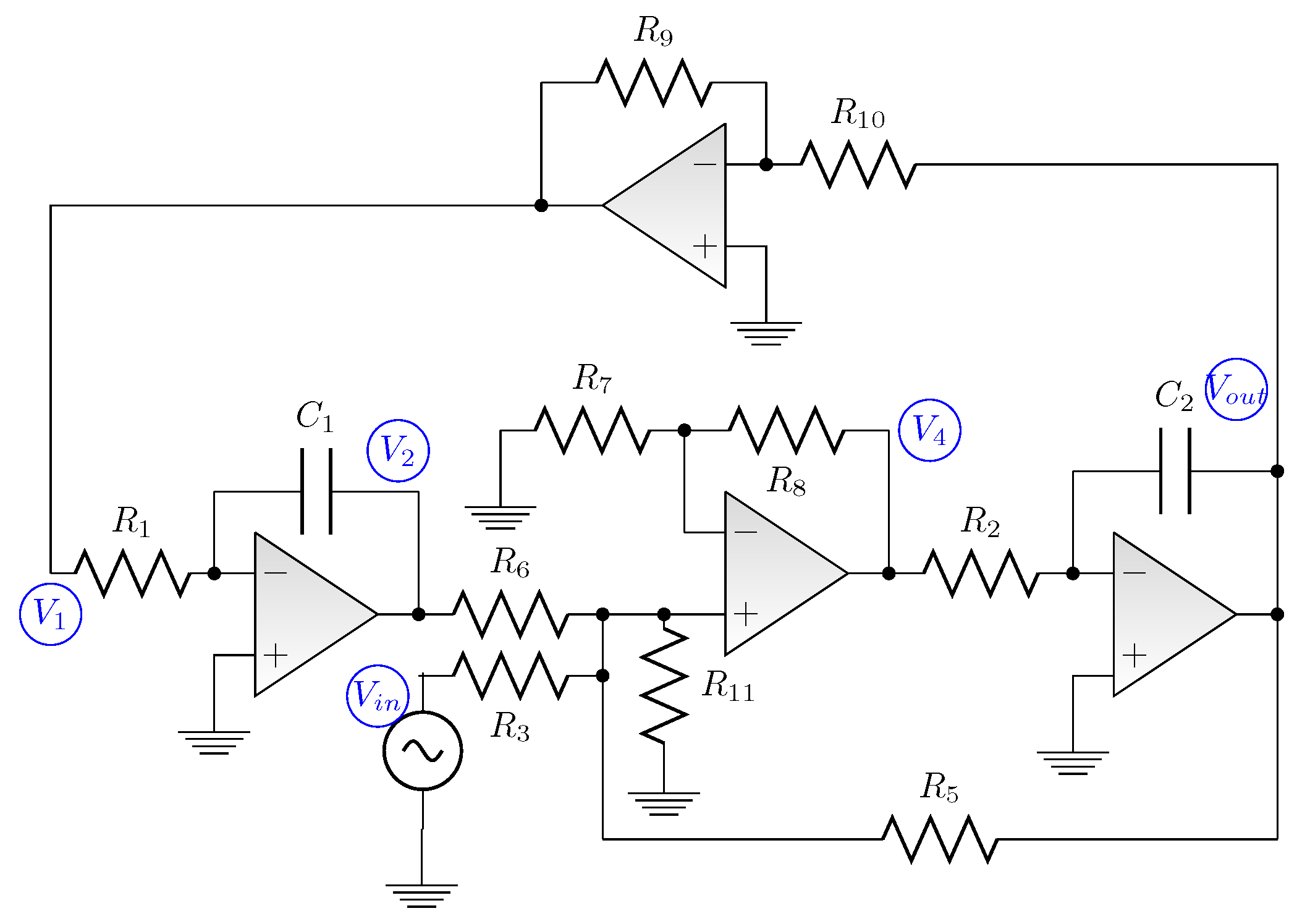
Figure 1. Biquadratic bandpass filter implemented with four opamps, ten resistors, and two capacitors.
Technologies 07 00064 g001
Figure 2. Signal flow graph of the: (a) opamp-RC filter shown in Figure 1, and (b) augmenting one feedback loop labeled K 1 from node V o u t to V 4 .
Technologies 07 00064 g002
Figure 3. Schematic diagram of the biquadratic bandpass filter implemented with opamps LM741.
Technologies 07 00064 g003
Figure 4. Frequency response of the biquadratic bandpass filter shown in Figure 3.
Technologies 07 00064 g004
Figure 5. Sensitivity analysis varying R 1 (red), R 2 (dark blue), R 3 (magenta), R 4 (gray), and R 5 (pink) in Figure 3.
Technologies 07 00064 g005
Figure 6. Sensitivity analysis varying R 6 (purple), R 7 (orange), R 8 (yellow), R 9 (dark orange), R 10 (green), and R 11 (blue) in Figure 3.
Technologies 07 00064 g006
Figure 7. Frequency response after updating the values of the resistances from sensitivity analysis.
Technologies 07 00064 g007
Figure 8. Measuring Q = 2920.06 from the frequency response shown in Figure 7.
Technologies 07 00064 g008
Figure 9. Frequency response when designing the filter to have Q = 122.79.
Technologies 07 00064 g009
Table 1. Poles of the bandpass filter with its associated Q.
Q ValuePole 1Pole 2
22.697−3.2629 × 10 8 −0.0023 × 10 8
2920.06−3.2734 × 10 8 −0.0025 × 10 8
122.79−3.2742 × 10 8 −0.0022 × 10 8