Article

Micro-CT Evaluation of Defects in Ti-6Al-4V Parts Fabricated by Metal Additive Manufacturing

1
Manufacturing Engineering Department, Georgia Southern University, Statesboro, GA 30458, USA
2
Department of Mechanical Engineering, Technical University of Denmark, 2800 Kgs. Lyngby, Denmark
3
UL International-Singapore Pte Ltd, Singapore 138628, Singapore
4
J. B. Speed School of Engineering, University of Louisville, Louisville, KY 40292, USA
5
ANSYS, Inc, Park City, UT 84098, USA
*
Author to whom correspondence should be addressed.
Technologies 2019, 7(2), 44; https://doi.org/10.3390/technologies7020044
Submission received: 3 May 2019 / Revised: 7 June 2019 / Accepted: 10 June 2019 / Published: 12 June 2019

Abstract

:
In this study, micro-computed tomography (CT) is utilized to detect defects of Ti-6Al-4V specimens fabricated by selective laser melting (SLM) and electron beam melting (EBM), which are two popular metal additive manufacturing methods. SLM and EBM specimens were fabricated with random defects at a specific porosity. The capability of micro-CT to evaluate inclusion defects in the SLM and EBM specimens is discussed. The porosity of EBM specimens was analyzed through image processing of CT single slices. An empirical method is also proposed to estimate the porosity of reconstructed models of the CT scan.

1. Introduction

The Additive Manufacturing (AM) is able to produce parts directly from a 3D CAD model, usually layer upon layer [1]. The powder-bed-fusion (PBF) based AM processes, such as selective laser melting (SLM) and electron beam melting (EBM) have been extensively employed for producing functional parts using pre-alloy powders (including stainless steel, cobalt chromium, titanium, etc.), in comparison with traditional casting or molding processes. In particular, the SLM- and EBM-produced Ti-6Al-4V parts are widely adopted in aerospace, biomedical and industrial fields due to their inherent properties of fracture resistance, fatigue behavior, corrosion resistance and biocompatibility [2]. The SLM process uses a focused laser beam to melt metallic powder inside a building chamber filled with inert gas. There is a recoating blade dispensing metallic powders on a build platform with a designated layer thickness. Parts are built up layer by layer on a build plate. The EBM process is similar to the SLM process. Instead of a laser beam, the EBM system generates an electron beam with a tungsten filament in the electron beam gun. The concentrated electron beam is accelerated to a tremendously high speed for achieving high energy electrons. When the electrons penetrate the powder surface and further into the powder grains, their velocity reduces. The kinetic energy converts into thermal energy so that the metal powder is melted [3]. Electromagnetic lenses are employed to control the electron beam preheating the building platform and melting the powder at a certain area, compared to the scanning galvanometer of the SLM process.
Properties of AM parts are dramatically influenced by the process conditions referring to processing parameters, scanning strategy and raw material characteristics. A great many studies have been conducted on the process parameter optimization for fully dense parts. Also, AM parts are evaluated on their porosity and inclusion defects through the Archimedes method or destructive method [4]. Although these methods are effective for estimating density and porosity, the evaluation processes are less efficient. It is also hard to exhibit the defect shape and actual location inside an AM part. In order to clearly display the part defects, some researchers employed Computed Tomography (CT) for analyzing defects and complex struts of SLM or EBM parts. Parthasarathy et al. [5] analyzed porous Ti-6Al-4V structures fabricated using the EBM process using a micro-CT scan and confirmed the fully interconnected pores with varied porosity. Van Bael et al. [6] designed porous SLM Ti-6Al-4V structures with different pore sizes based on micro-CT image analysis and optimized the robustness and controllability of the production. Saâdaoui et al. [7] demonstrates the suitability of X-ray tomography for both defect detection and predictive mechanical strength estimation in AM zirconia materials. Haleem et al. [8] studied the role of CT for design and development of orthopaedic models using AM technologies. The research concluded that this scanning technology has various applications to enhance AM in the field of orthopaedics. Kim et al. [9] studied the pore structures of AM metal parts with X-ray CT and found that the quantitative results depend on accurately segmenting the CT images. Ortega et al. [10] also verified the CT capability for both porosity detection and geometrical reconstruction of Inconel 718 components made by SLM. However, few investigations were carried out using CT to detect AM metal parts which have seeded defects at a specific porosity. This paper aims to study the micro-CT capability in detecting defects of SLM and EBM Ti-6Al-4V specimens. The possibility and approaches of porosity determination through CT scanning results are also discussed.

2. Fundamentals of Micro-CT

Micro-CT uses the penetrating abilities of X-rays to examine the internal defects of objects [11]. An X-ray source is used to send radiation through a part. Material discontinuities such as voids or changes in contour affect the degree of radiation absorption. The unabsorbed radiation that passes through the part is recorded to indicate the internal characteristics such as voids, pores or cracks. The intensity of the X-ray is modified according to the internal structure of the specimen to generate CT slices. Each CT slice is subdivided into a 3D matrix of volumetric elements (voxels). The intensity of radiation is measured by a detector. In a slice, the average attenuation value within each voxel is calculated from the intensity readings and assigned as its CT number. Generally, grayscale in the CT slice image is denoted as the CT number. Denser material is rendered with a higher grayscale value (bright region) in the image, while voids or defects are displayed as dark. However, the image grayscale cannot represent the actual density information of the specimen. Image brightness and contrast are also influenced by the CT setup. Gradient grayscale distribution is even shown in the same scenario at a consistent configuration.

3. Experiments

3.1. Specimen Fabrication

SLM- and EBM-produced specimens can be fabricated with embedded defects by varying process parameters. Depending on energy input, SLM has two types of defects, i.e., keyhole defects and lack-of-fusion defects [12,13]. An EOS M270 Direct Metal Laser Sintering (DMLS) system was utilized for fabricating SLM specimens, with Raymor Ti-6Al-4V powder (Grade 23). Scan speed was varied with constant laser power (120 W), hatch spacing (0.1 mm) and layer thickness (0.03 mm). The EBM system has a self-protection mechanism to prevent high energy input so only lack-of-fusion defects were created by varying line offset and focus offset. Arcam Titanium Ti-6Al-4V ELI powder was used for fabricating EBM specimens (layer thickness 0.05 mm) with an Arcam S400 EBM system. Line offset and focus offset were adjusted respectively for generating defects. Other processing parameters were set to factory default value. In order to evaluate the detecting capability of micro-CT, cubical specimens (10 × 10 × 10 mm) were fabricated at different porosities, as shown in Table 1. Each specimen’s density was measured using the Archimedes method and then compared with the nominal density of the Ti-6Al-4V material to estimate porosity (RD).

3.2. Micro-CT Evaluation

The scan was carried out using a micro-CT scanner (Model ACTIS 200/225 Ffi-HR CT/DR system. BIR Inc., Chicago, IL with built-in X-ray system FXE 225.20, Fein Focus USA). As shown in Figure 1, the scanner consists of a turnable stage, an X-ray source, an image intensifier, and a CCD camera. Different from regular clinical CT, the micro-CT scanner rotates the specimen on the stage with a fixed X-ray source (voltage 135 KeV and current 0.059 mA) and an image intensifier. The scanner’s resolution depends on the physical position of specimen. In this study, each scan consists of 107 slices. Slices were created 7 µm apart from each other, parallel to the building plane of specimens. The voxel had a size of 7 × 7 × 7 µm. Three dimensional reconstruction was performed using VGStudio MAX software package for visualization and analysis.

4. Results and Discussion

4.1. Characteristics of SLM Specimens

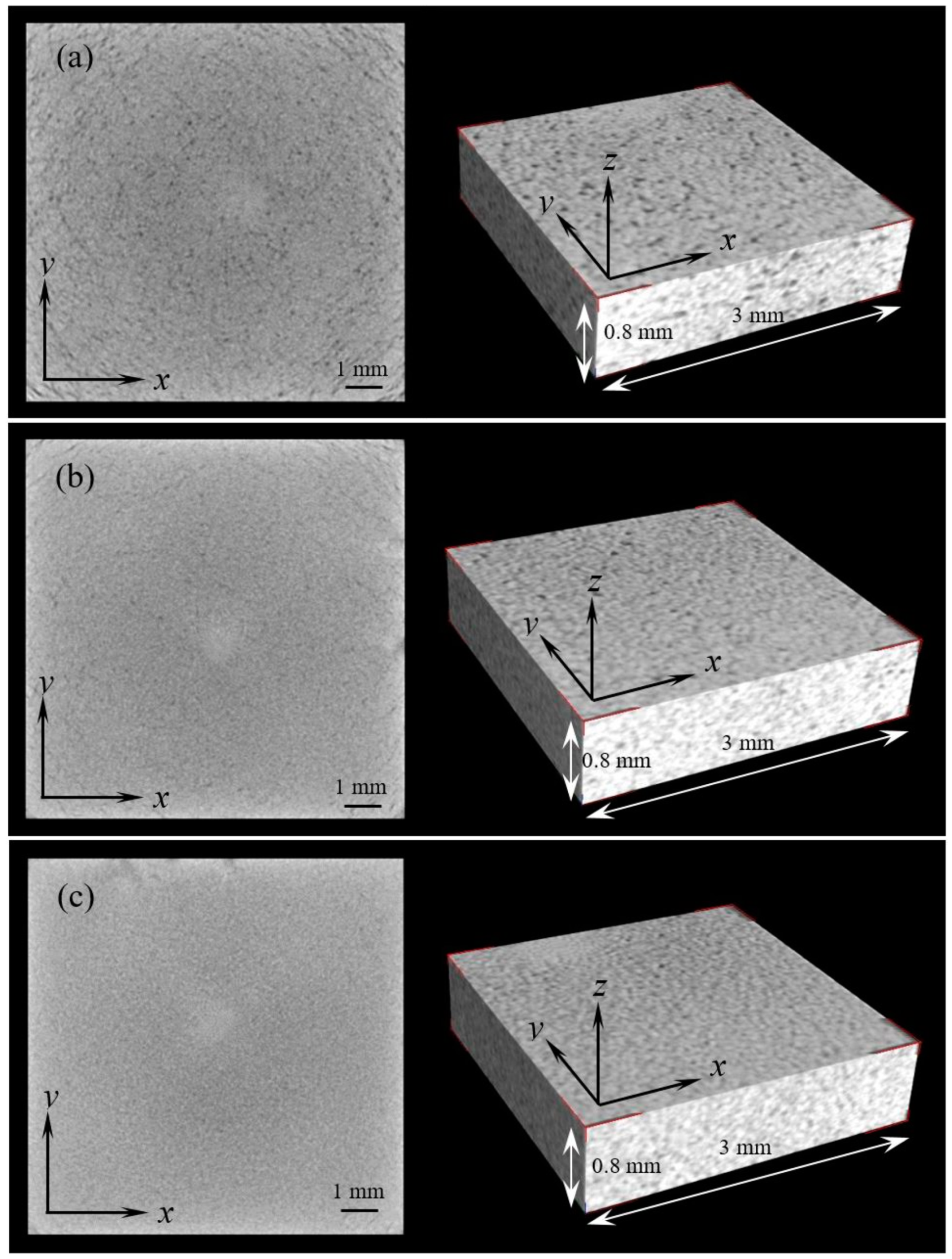
Energy density refers to the average applied energy per volume of material during scanning of one layer [14]. With a high energy density, the SLM process has a complex microscopic or macroscopic transport phenomenon in the molten metal. Spherical voids (keyhole defects) can be formed in SLM specimens. Figure 2 shows the typical single slices of the CT scan and the locally reconstructed models (3 × 3 × 0.8 mm) of SLM specimens.
The single slice and reconstructed model present rough surfaces when the SLM specimen has a porosity around 6%, as shown in Figure 2a. According to the CT theory, the bulk material is displayed as white while the defect is dark. The single slice shows an irregular texture variation. Thus, it can be inferred that there are a large amount of inclusion defects. However, only a few defects can be located from the slices and the reconstructed model due to the limited detectability (defect size ≥ 21 μm for visualization) of the micro-CT machine used in this study. Most defects are comparable or less than 21 μm so that they are hardly discernable from the bulk material. It is noted that the texture of the single slice becomes relatively uniform when RD is reduced to 2%, as shown in Figure 2b. However, inclusion defects can be affirmed, compared to the image of low porosity single slice (Figure 2c, RD = 0.5%).
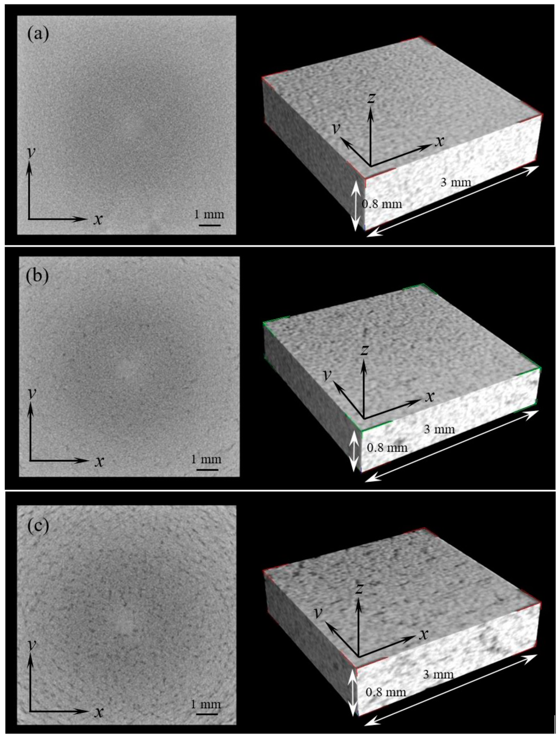
The reduced energy density will generate lack-of-fusion defects with an irregular morphology. Figure 3 shows the micro-CT single slices and reconstructed models of SLM specimens with lack-of-fusion defects. Similar to the single slice in Figure 2c, the image with low porosity (RD = 0.3%) also shows equal grayscale distribution, as shown in Figure 3a. The increased porosity results in a rough texture of the single slices and the reconstructed models. It indicates that most defects are randomly distributed on the cross section of specimens with small dimensions, but it is difficult to identify the defect morphology and locate small defects.

4.2. Characteristics of EBM Specimens

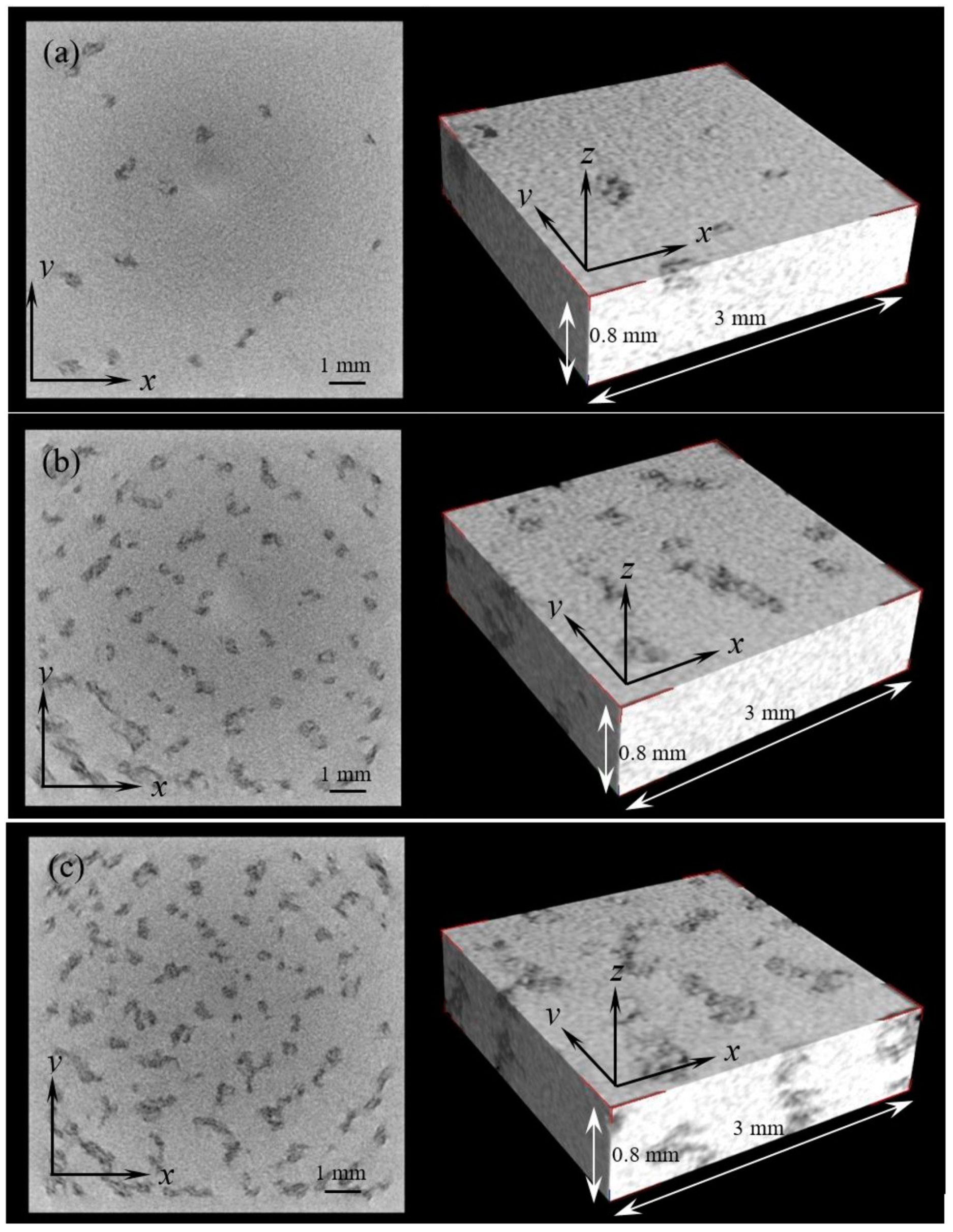
Line offset (LO) refers to the distance between two hatch lines, similar to hatch spacing in SLM. The increased line offset will reduce the energy density, which exacerbates the inclusion defect within EBM specimens. Defects of EBM specimens can be easily detected from the CT single slice, even at a low porosity, as shown in Figure 4a. This indicates that most lack-of-fusion EBM defects are larger than the SLM defects. The grayscale distribution of non-defective area is successive. The material composition and properties are homogeneous, resulting in uniform absorption of the X-ray radiation. The defect amount increases with the increased line offset value correspondingly. Higher porosity usually comes with larger defects, as shown in Figure 4b,c.
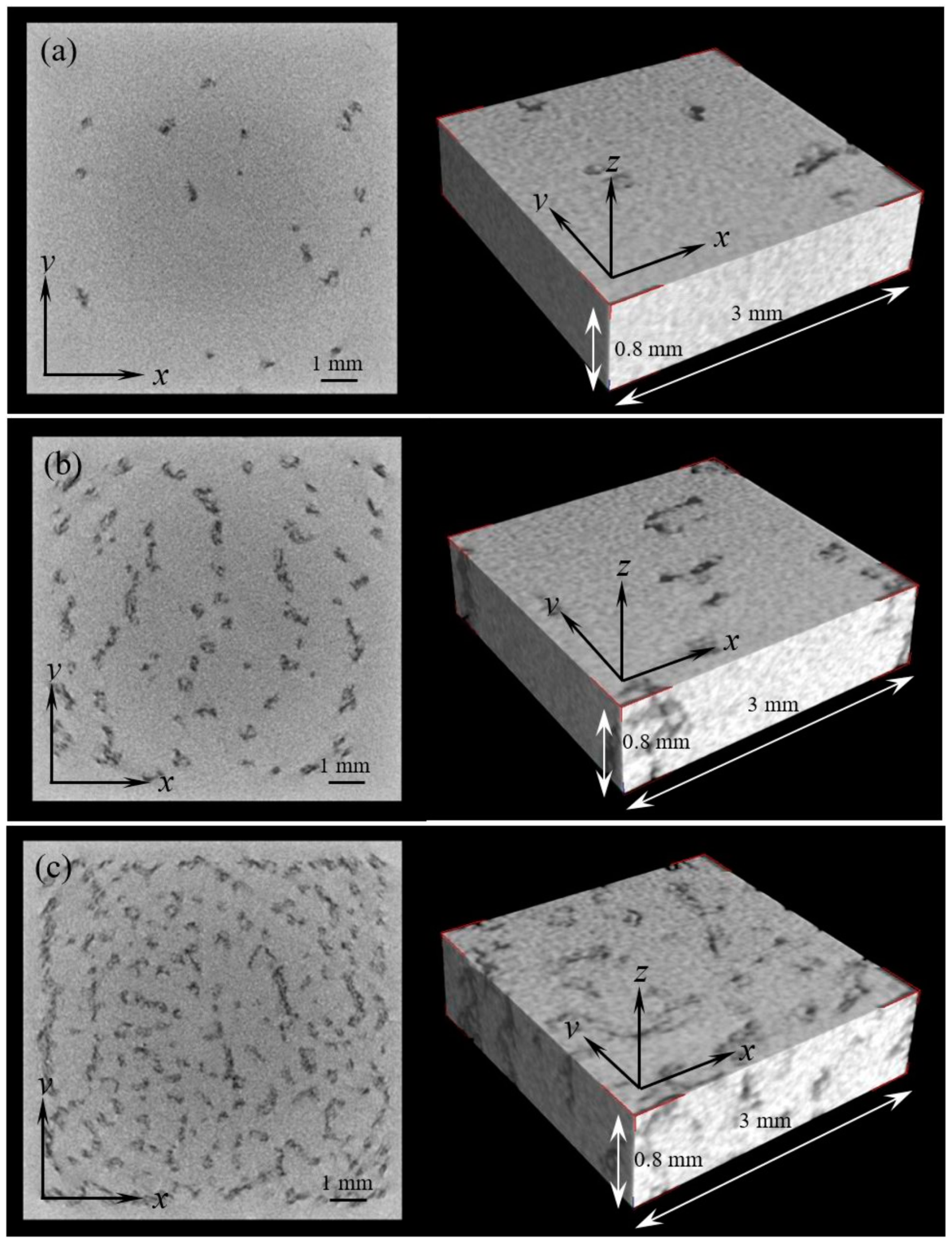
Focus offset (FO) is the additional current running through the respective electromagnetic coil and can be translated into an offset of the focal plane from its zero position [15]. Increasing the focus offset causes an enlarged diameter of focal spot and beam area, which lowers the energy density and generates defects. Thus, it is noted that more defects are visible from the single slices and the reconstructed models in Figure 5b,c. The morphology of focus offset defects are comparable to the line offset defects. However, the size of the focus offset defects is smaller than the line offset defects.
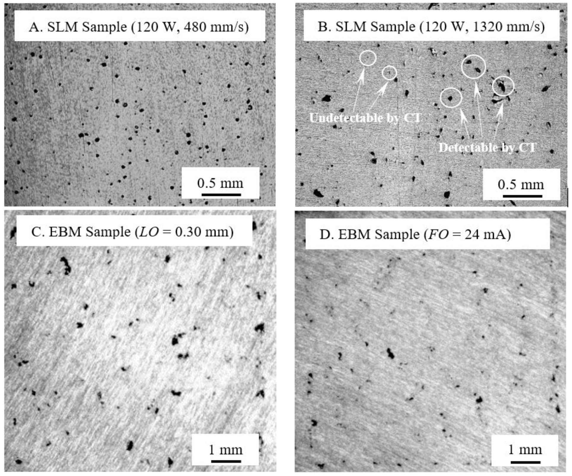
The micro-CT evaluation of the SLM and EBM specimens shows different characteristics of defects. Compared to SLM specimens, the defects in an EBM specimen are more easily detected by the micro-CT scanning due to their size features. The morphology and distribution of defects can be well described by the single slices or reconstructed models. The size of the SLM defects is comparable or slightly larger than the visualization threshold (21 µm) of the micro-CT machine used. The single slices only show a rough texture even though SLM specimen has a higher porosity level. Thus, SLM slices are not as easy to use for morphological analysis of defects as EBM slices. Compared to the optical microscopy of the SLM and EBM samples, the detectability of defects using a micro-CT is less advantageous, especially for small defects of SLM samples. When the size of defects is close or smaller than the CT visualization threshold (for example, 21 µm for the CT machine used in this study), it can hardly identify the location and profile of the defects via CT scanning. Some microscopic images of cross-sectioned SLM and EBM samples are shown in Figure 6. It is noted that the lack-of-fusion defects exhibit a profile with sharp edges, which are more detrimental to the mechanical properties of the SLM or EBM parts. A certain amount of small defects (Figure 6B) are hardly detected by micro-CT. Some studies have been conducted about the impact of defects on the fatigue behaviors of metal additive manufacturing parts [16,17,18]. It can be concluded that the detectability of small defects in SLM parts is more critical and demands a high resolution CT scan (highly recommend voxel size < 7 μm) or other auxiliary porosity identification methodologies.

4.3. Porosity Determination

4.3.1. Image Correction to Single Slice

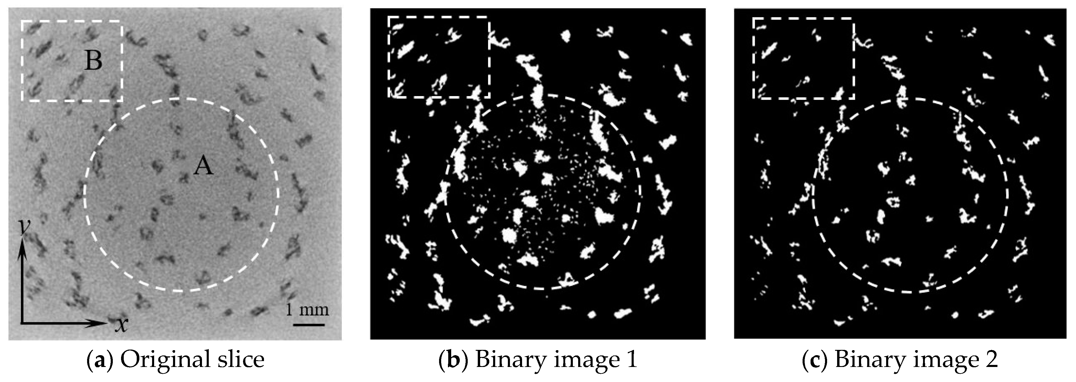
Due to the large size of defects, the single slice of EBM specimen can be directly utilized for image processing to estimate porosity. However, as the CT slices are correlated with machine setup and manipulation parameters, the grayscale can only represent the relative attenuation value for describing radiation absorption. Homogeneous material is evenly expressed by the gradient grayscale in a CT slice of EBM specimen, as shown in Figure 7a, which refers to radiodensity inconsistency. Areas “A” and “B” are believed to be alike, but the grayscale of area “A” (near the center) is apparently darker than area B (near the boundary). It is hard to select a uniform grayscale threshold to convert a single slice to binary images to highlight the defective region, as well as the porosity determination. As shown in Figure 7b, when an intermediate grayscale threshold is applied to the original slice image for binary image conversion, there are a certain amount of tiny undesired white spots not being filtered (within dashed circle). However, if a higher grayscale threshold is adopted, the morphological features of the defective area, specifically near the boundary in Figure 7c, are altered dramatically.
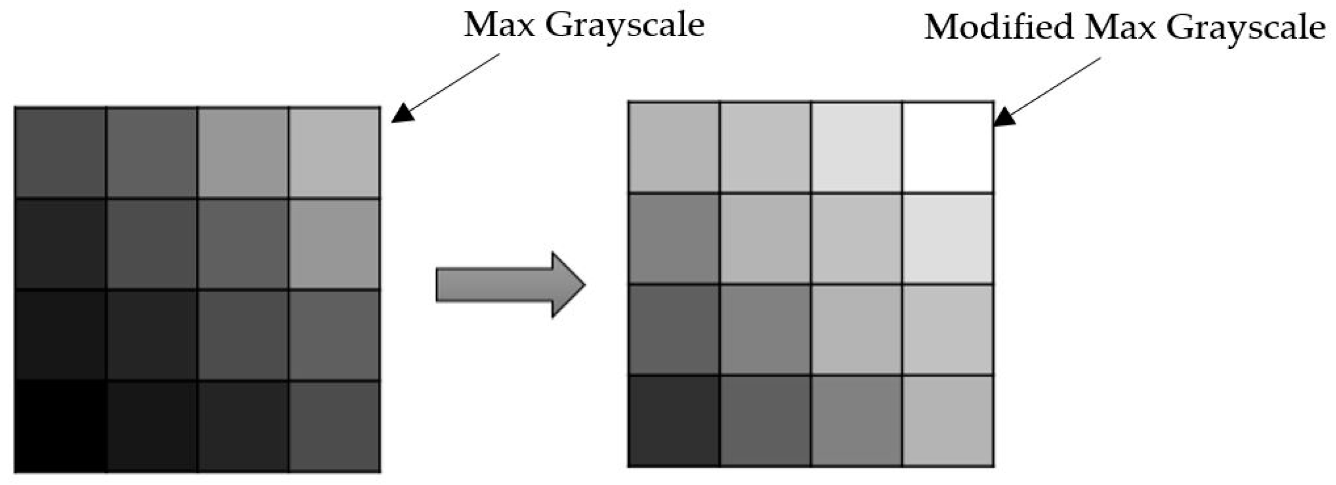
There are two approaches to solving grayscale inconsistency in a single slice image. The first one is to set up multiple thresholds when converting the original image to binary. The darker area, such as the central area “A” in Figure 7a, could be applied with a higher threshold, while the peripheral area with regular threshold. However, a boundary between areas needs to be pre-determined before setting up multi-threshold. Differentiated image processing also makes the conversion complex. An alternative approach is to correct the single slice image with uniform grayscale levels before binary image conversion. The corrected image is suitable for further conversion with a unique threshold. For image correction, the original slice image was first segmented into cells. The maximum grayscale value of each cell was identified and then assigned with an equal value. Correspondingly, the grayscale of other pixels within this cell was proportionally adjusted to a new value according to the modified maximum grayscale, as shown in Figure 8. By doing this, all cells are unified to the same grayscale level.
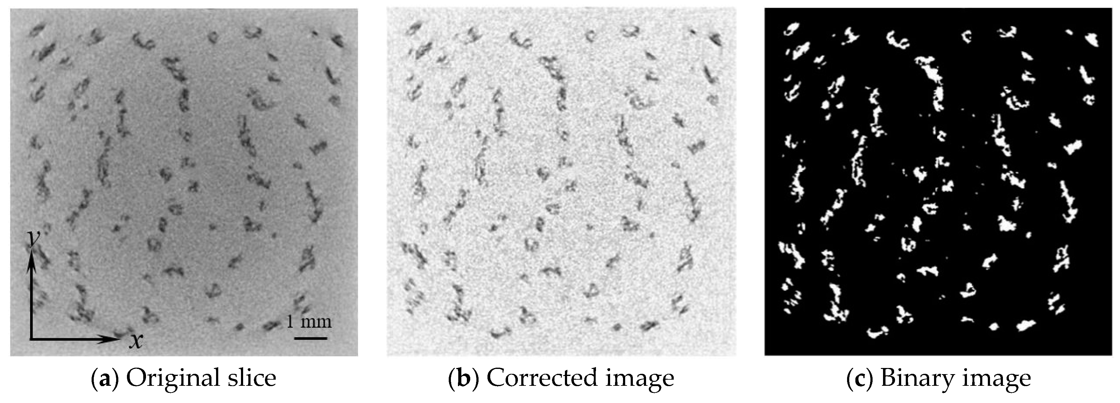
An example of image correction is shown in Figure 9. It can be seen that the inconsistency of grayscale between the center and boundary is improved in the corrected image. The morphological features of defects are maintained after correction. The inconvenience of image conversion due to grayscale inconsistency is completely eliminated. The corrected image ensures the accuracy of porosity estimation using image processing.
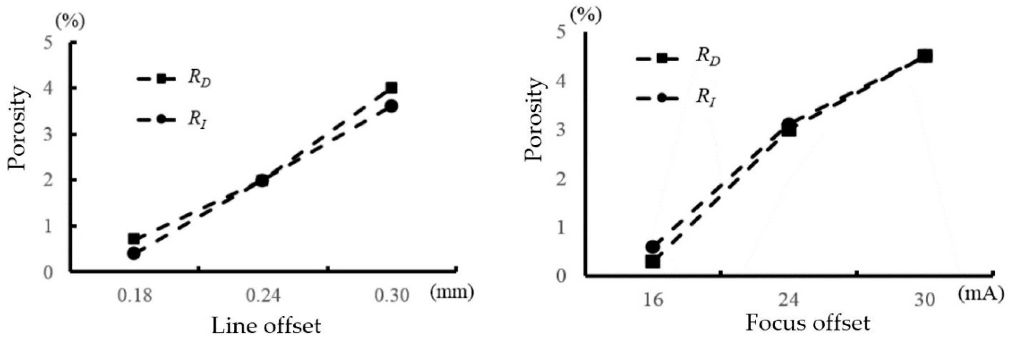
Through a binary image, defective areas (white color) can be summed up and then divided by the entire image area to calculate “image processing porosity (RI)”. The comparison between RD and RI is shown in Figure 10. It can be seen that RI is very close to RD as long as the proper threshold is selected when converting the corrected image to a binary image. Moreover, once a threshold is calibrated for estimating porosity based on one binary image, no further calibration is required for the other images because the corrected images adopt the same grayscale level. Hence, porosity estimation based on the single slices of micro-CT is feasible for the specimens with large internal defects such as porous EBM specimens.

4.3.2. Selection of Grayscale Threshold for Reconstructed Model

The reconstructed model from CT slices consists of a continuous set of voxels, which represents a specific area of the object. The grayscale of each voxel provides information on the material properties in this area. In the case of a CT scan, the grayscale variation is capable of capturing the characteristics of the reconstructed model, including material properties and inner structures. A well selected grayscale threshold is able to determine the entire structure of the object with a high accuracy.
The defects of SLM or EBM specimens are of great interest in this study. It is assumed that dense regions in a reconstructed model are continuum material without any property variation. Defective regions are differentiated from the dense regions due to their low grayscale value. Grayscale threshold selection is calibrated to match the porosity results of the Archimedes measurement. However, since the grayscale is subject to change due to the slice brightness or contrast controlled by the CT setup, it is hard to select a uniform grayscale threshold for all the SLM or EBM specimens. Even for a consistent configuration, the grayscale threshold for each specimen is slightly different. Generally, Hounsfield unit (HU) is utilized to linearly transform the original CT number (grayscale) of a voxel into a quantitative scale for describing radiodensity [19], in order to reduce the effect of CT setup variation. However, similar to the single slice, the radiodensity variation also results in grayscale inconsistency in a reconstructed model. Thus, it can be concluded that HU transformation does not ensure a uniform grayscale threshold for all the scans of SLM or EBM specimens.
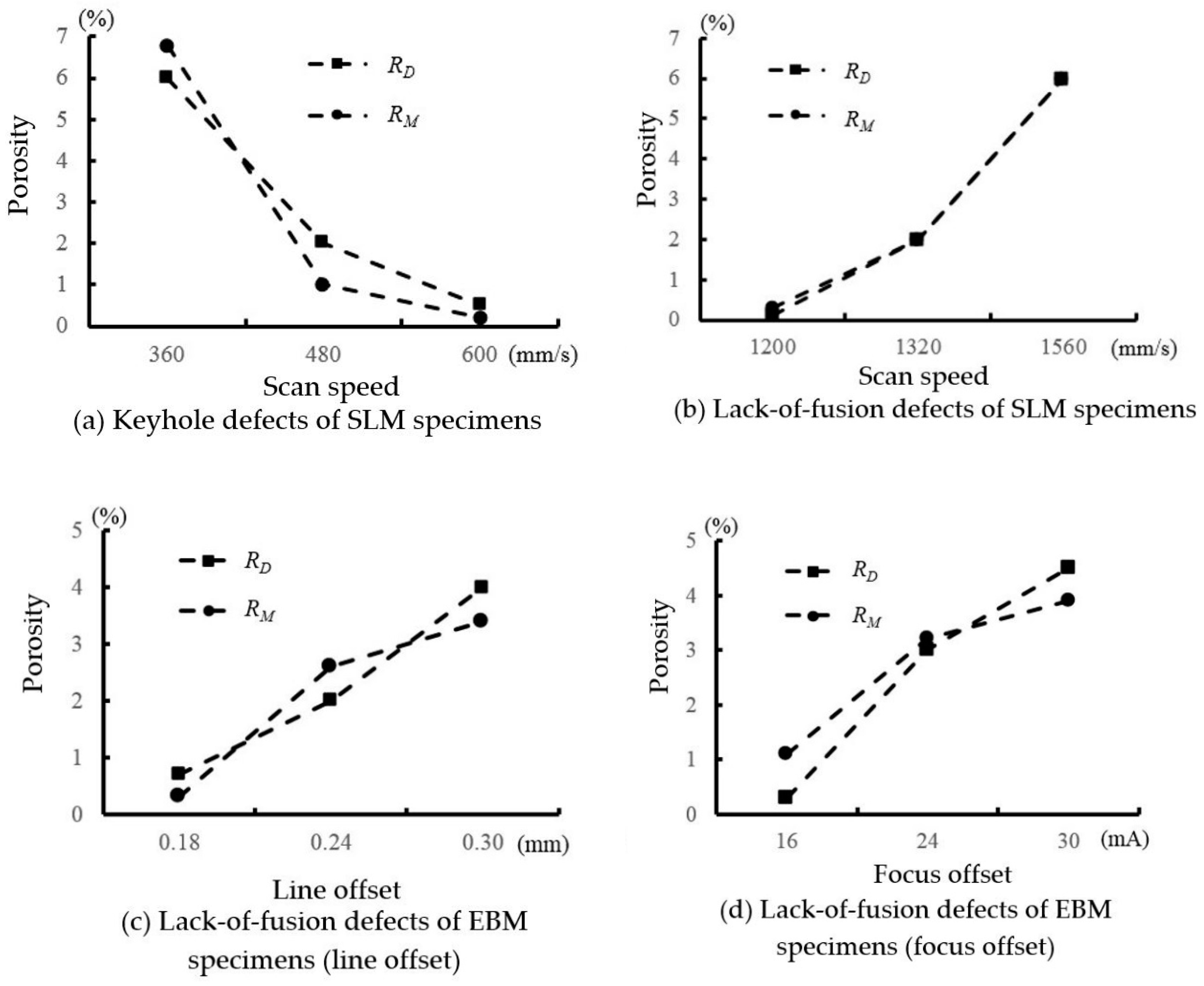
An empirical method is proposed in this study to estimate the porosity of reconstructed models. The grayscale threshold is firstly adjusted for single slice images of a SLM or EBM specimen to match the porosity (RD). Then, a neutralized threshold is selected for the reconstructed models. A porosity (RM) obtained by using the neutralized threshold is compared to the Archimedes porosity (RD), as shown in Figure 11.
Basically, the porosity (RM) has a similar increasing or decreasing trend compared to the Archimedes porosity (RD). Only Figure 11b shows a good match between RM and RD, compared to other diagrams. Apparently, the neutralized grayscale threshold is not the best solution to estimate the porosity for the reconstructed models because the grayscale inconsistency is a result of the mutual influence of the CT setup and the radiodensity variations. It is complicated to compensate for all these variations to determine a unique grayscale. Thus, the neutralized grayscale threshold could only be employed for an approximate porosity estimation when the single slice’s micro-CT scans are reconstructed into a 3D model, especially for the EBM specimens with large inclusion defects.

5. Conclusions

Micro-CT is capable of detecting defects in SLM and EBM specimens. However, the machine setup and CT detectability play a critical role in defect visualization. Defects show dissimilar size characteristics between SLM and EBM processes. In this study, the contour features of SLM defects were hard to be identified in the CT scans due to their small sizes, but the EBM stochastic defects were large enough to be visualized.
The dense specimens usually display a homogeneous grayscale variation in the CT scans, but the defects cause irregular variations of brightness and darkness in localized areas of single slices. The porosity of EBM specimens can be estimated using the single slices through image processing, while single slices of SLM specimens only show a rough texture and cannot be used for porosity analysis. In addition, when defects are reconstructed into a 3D model, the approximate porosity can be obtained by carefully selecting a neutralized grayscale threshold. Although the accuracy is limited, this method proposes a rapid estimation of the porosity of a reconstructed model of a CT scan.

Author Contributions

Conceptualization, H.G. and T.S.; methodology, H.G. and V.K.N.; validation, H.G., V.K.N. and K.R.; writing—original draft preparation, H.G.; writing—review and editing, H.G.; supervision, T.S. and B.S.; project administration, T.S. and B.S.

Funding

This research was funded by the Office of Naval Research, awards number N00014-09-1-0147 and N00014-10-1-0800, Technical Monitor: Dr. Ignacio Perez.

Acknowledgments

The authors express their gratitude to Michael Voor and Seid Waddell of the Department of Orthopaedic Surgery, and the staff of the Rapid Prototyping Center at the University of Louisville.

Conflicts of Interest

The authors declare no conflict of interest.

References

  1. Gibson, I.; Rosen, D.W.; Stucker, B. Additive Manufacturing Technologies: Rapid Prototyping to Direct Digital Manufacturing, 2nd ed.; Springer: New York, NY, USA, 2015; pp. 1–18. [Google Scholar]
  2. Soboyejo, W.O.; Srivatsan, T.S. Advanced Structural Materials: Properties, Design Optimization, and Applications; CRC Press: Boca Raton, FL, USA, 2006; pp. 359–400. [Google Scholar]
  3. Hiemenz, J. Electron beam melting. Adv. Mater. Proc. 2007, 165, 45–46. [Google Scholar]
  4. Spierings, A.B.; Schneider, M. Comparison of density measurement techniques for additive manufactured metallic parts. Rapid Prototyping J. 2011, 17, 380–386. [Google Scholar] [CrossRef]
  5. Parthasarathy, J.; Starly, B.; Ramana, S.; Christensen, A. Mechanical evaluation of porous titanium (Ti6Al4V) structures with electron beam melting (EBM). J. Mech. Behav. Biomed. 2010, 3, 249–259. [Google Scholar] [CrossRef] [PubMed]
  6. Van Bael, S.; Kerckhofs, G.; Moesen, M.; Pyka, G.; Schrooten, J.; Kruth, J.P. Micro-CT-based improvement of geometrical and mechanical controllability of selective laser melted Ti6Al4V porous structures. Mat. Sci. Eng. A-Struct. 2011, 528, 7423–7431. [Google Scholar] [CrossRef]
  7. Saâdaoui, M.; Khaldoun, F.; Adrien, J.; Reveron, H.; Chevalier, J. X-ray tomography of additive-manufactured zirconia: processing defects – strength relations. J. Eur. Ceram. Soc. 2019, in press. [Google Scholar]
  8. Haleem, A.; Javaid, M. Role of CT and MRI in the design and development of orthopaedic model using additive manufacturing. J. Clin. Ortho. Trauma. 2018, 9, 213–217. [Google Scholar] [CrossRef] [PubMed]
  9. Kim, F.H.; Moylan, S.P.; Garboczi, E.J.; Slotwinski, J.A. Investigation of pore structure in cobalt chrome additively manufactured parts using X-ray computed tomography and three-dimensional image analysis. Addit. Manuf. 2017, 17, 23–38. [Google Scholar] [CrossRef]
  10. Ortega, N.; Martínez, S.; Cerrillo, I.; Lamikiz, A.; Ukar, E. Computed tomography approach to quality control of the Inconel 718 components obtained by additive manufacturing (SLM). Procedia Manuf. 2017, 13, 116–123. [Google Scholar] [CrossRef]
  11. Carvalho, A.A.; Rebello, J.M.A.; Souza, M.P.V.; Sagrilo, L.V.S.; Soares, S.D. Reliability of non-destructive test techniques in the inspection of pipelines used in the oil industry. Int. J. Press. Vessels Pip. 2008, 85, 745–751. [Google Scholar] [CrossRef]
  12. Gong, H.; Rafi, K.; Gu, H.; Starr, T.; Stucker, B. Analysis of defect generation in Ti-6Al-4V parts made using powder bed fusion additive manufacturing processes. Addit. Manuf. 2014, 1–4, 87–98. [Google Scholar] [CrossRef]
  13. Gong, H.; Rafi, K.; Gu, H.; Janaki Ram, G.D.; Starr, T.; Stucker, B. Influence of defects on mechanical properties of Ti-6Al-4V components produced by selective laser melting and electron beam melting. Mater. Des. 2015, 86, 545–554. [Google Scholar] [CrossRef]
  14. Thijs, L.; Verhaeghe, F.; Craeghs, T.; Van Humbeeck, J.; Kruth, J.P. A study of the microstructural evolution during selective laser melting of Ti-6Al-4V. Acta Mater. 2010, 58, 3303–3312. [Google Scholar] [CrossRef]
  15. Schwerdtfeger, J.; Singer, R.F.; Körner, C. In situ flaw detection by IR-imaging during electron beam melting. Rapid Prototyping J. 2012, 18, 259–263. [Google Scholar] [CrossRef]
  16. Hovig, E.W.; Azar, A.S.; Sunding, M.F.; Andreassen, E.; Sørby, K. High cycle fatigue life estimation of materials processed by laser powder bed fusion. Fatigue Fract. Eng. Mater. Struct. 2019, 42, 1454–1466. [Google Scholar] [CrossRef]
  17. Beevers, E.; Brandão, A.D.; Gumpinger, J.; Gschweitl, M.; Seyfert, C.; Hofbauer, P.; Rohr, T.; Ghidini, T. Fatigue properties and material characteristics of additively manufactured AlSi10Mg – Effect of the contour parameter on the microstructure, density, residual stress, roughness and mechanical properties. Int. J. Fatigue 2018, 117, 148–162. [Google Scholar] [CrossRef]
  18. Romano, S.; Brückner-Foit, A.; Brandão, A.; Gumpinger, J.; Ghidini, T.; Beretta, S. Fatigue properties of AlSi10Mg obtained by additive manufacturing: defect-based modelling and prediction of fatigue strength. Eng. Fract. Mech. 2018, 187, 165–189. [Google Scholar] [CrossRef]
  19. Brown, S.; Bailey, D.L.; Willowson, K.; Baldock, C. Investigation of the relationship between linear attenuation coefficients and CT Hounsfield units using radionuclides for SPECT. Appl. Radiat. Isot. 2008, 66, 1206–1212. [Google Scholar] [CrossRef] [PubMed]
Figure 1. Micro- Computed Tomography (CT) equipment.
Technologies 07 00044 g001
Figure 2. Single slices and locally reconstructed models of SLM specimens with keyhole defects. (a) V = 360 mm/s, RD = 6.0%. (b) V = 480 mm/s, RD = 2.0%. (c) V = 600 mm/s, RD = 0.5%.
Technologies 07 00044 g002
Figure 3. Single slices and locally reconstructed models of SLM specimens with lack-of-fusion defects. (a) V = 1080 mm/s, RD = 0.3%. (b) V = 1320 mm/s, RD = 2.0%. (c) V = 1560 mm/s, RD = 6.0%.
Technologies 07 00044 g003
Figure 4. Single slices and locally reconstructed models of EBM specimens (varied line offset). (a) LO = 0.18 mm, RD = 0.7%. (b) LO = 0.24 mm, RD = 2.0%. (c) LO = 0.30 mm, RD = 4.0%.
Technologies 07 00044 g004
Figure 5. Single slices and locally reconstructed models of EBM specimens (varied focus offset). (a) FO = 16 mA, RD = 0.3%. (b) FO = 20 mA, RD = 3.0%. (c) FO = 24 mA, RD = 4.5%.
Technologies 07 00044 g005
Figure 6. Optical microscopic image of cross-section surfaces of SLM and EBM samples.
Technologies 07 00044 g006
Figure 7. Image processing of a single slice of CT scanned EBM specimen.
Technologies 07 00044 g007
Figure 8. Schematic of grayscale adjustment to an individual cell (16 pixels).
Technologies 07 00044 g008
Figure 9. Example of EBM single slice image correction and binary image.
Technologies 07 00044 g009
Figure 10. Comparison between RD and RI (EBM specimens).
Technologies 07 00044 g010
Figure 11. Comparison between RD and RM.
Technologies 07 00044 g011
Table 1. Parameters and porosity of selective laser melting (SLM) and electron beam melting (EBM) specimens.
AM Process *Parameters **RD
SLMKeyhole defect
(high energy density)
V = 360 mm/s6.0%
V = 480 mm/s2.0%
V = 600 mm/s0.5%
Lack-of-fusion defect
(low energy density)
V = 1080 mm/s0.3%
V = 1320 mm/s2.0%
V = 1560 mm/s6.0%
EBMLack-of-fusion defect
(low energy density)
LO = 0.18 mm0.7%
LO = 0.24 mm2.0%
LO = 0.30 mm4.0%
Lack-of-fusion defect
(low energy density)
FO = 16 mA0.3%
FO = 20 mA3.0%
FO = 24 mA4.5%
* AM = Additive Manufacturing. ** V = scan speed, LO = line offset, FO = focus offset.