Article

Chipless Radio Frequency Identification (RFID) Sensor for Angular Rotation Monitoring

by
Simone Genovesi
1,*,
Filippo Costa
1,
Michele Borgese
2,
Francesco Alessio Dicandia
2 and
Giuliano Manara
1
1
Dipartimento di Ingegneria dell’Informazione, University of Pisa, Via Caruso 16, 56122 Pisa, Italy
2
GreenWaves, 20064 Milan, Italy
*
Author to whom correspondence should be addressed.
Technologies 2018, 6(3), 61; https://doi.org/10.3390/technologies6030061
Submission received: 31 May 2018 / Revised: 25 June 2018 / Accepted: 26 June 2018 / Published: 29 June 2018
(This article belongs to the Special Issue Chipless RFID Technologies)

Abstract

:
A novel, chipless, Radio Frequency Identification (RFID) sensor is proposed for monitoring angular rotation. The rotation state is recovered by collecting the cross polar response of a tag, based on a periodic surface composed of a set of dipoles. The encoding mechanism allows the sensor to be very robust, even if it is applied on metallic objects, or in an environment with strong multipath. The proposed sensor does not require a large operational bandwidth. Instead, only a small set of reading frequencies are required. The number of reading frequencies required is dependent on the number of the employed dipoles. It is demonstrated that the rotation state of an object can be monitored within a span of 180 degrees, with up to a three-degree resolution, by employing a chipless RFID sensor comprising of four dipoles. The far field reading scheme and the absence of any electronics device allow the sensor to be employed in harsh environments.

1. Introduction

The identification paradigm offered by Radio Frequency Identification (RFID) technology has been increasingly exploited in more and more applications, such as inventory management, access control, assembly process monitoring and supply chain integration [1,2]. Together with this employment based on the encoding of a univocal identification (ID) number in the electromagnetic footprint of the RFID tag, (which has reached a good point of maturity), an additional declination of the RFID technology is represented by the realization of sensors. Several directions have been explored in this sense, spanning from something as simple as measuring temperature [3,4] and gas [5,6], to more complex usage in healthcare [7,8], structural monitoring [9,10], localization [11,12,13], as well as food chain control [14,15]. However, although the presence of an integrated circuit (IC) in a RFID tag guarantees interesting features (in terms of large data storage and reprogrammable capability), it also poses some constraints on the item price and operating environmental conditions.
These shortcomings have fostered the research toward chipless RFID tags, which encode the information in the electromagnetic (EM) footprint of the tag without resorting to an IC. This task obviously presents different challenges that have been faced in the last years by original approaches to the exploitation of different EM signature strategies for encoding the information. For example, the ID has been stored in the frequency response of the tag [16,17], as well as in the timing of the response [18,19],and also by exploiting the phase [20,21] or the polarization [22,23] of the scattered field. Moreover, a suitably designed chipless RFID can be also employed as a sensor for monitoring quantities, such as humidity [24,25,26], temperature [27], and gas [28], even in harsh environments [29].
An interesting quantity to be monitored is represented by the rotation angle of an object revolving on its axis. Recently, some solutions aimed at estimating the rotation angle, or measuring the angular velocity, have been proposed. In Reference [23], the co-polar response of a chipless RFID tag to a linearly polarized incident field has been exploited in order to detect the tag orientation. In particular, the provided accuracy for the estimated rotation angle is equal to 20 degrees, whereas the coding capacity is 6 bits if three resonant elements are used. In Reference [30], a coplanar waveguide (CPW) loaded with a horn-shaped split ring resonator (SRR) is employed for realizing a rotation sensor operating at a single frequency with a dynamic range of up to seven degrees. A rotation sensor comprised of two meandered U-shaped resonators, coupled to a microstrip line, is described in Reference [31]. This metamaterial-inspired sensor exhibits a dynamic range of up to 180 degrees and requires a bandwidth of 350 MHz around the center frequency of 1.0 GHz, since the angular encoding is based on the downshift of the minimum transmission coefficient of the device. A procedure for recovering the angular velocity by using two circularly polarized antennas with a demodulator for Frequency Modulated (FM) carriers, is shown in Reference [32]. A solution relying on ultra-high frequency (UHF) RFID tags has been presented in Reference [33], where the rotation speed is inferred by exploiting the level of polarization mismatch in the time domain between the reader and the tag. A preliminary study on the possible use of a cross polarization scattering (CPS) system has been presented in Reference [34,35], using chipless RFID tags to design angular rotation sensors, where different resonator geometries (loop, SRR, stubbed loop and dipole) were investigated. A coplanar waveguide loaded with SRRs has been proposed in Reference [36] for measuring angular displacement and velocity. More specifically, two circular chains of rectangular SRRs are etched in the layer applied to the rotor, whereas a CPW transmission line loaded with two pairs of SRRs is placed on the stator, (with a small airgap in between the two layers). The rotor motion modulates the amplitude of the carrier and thus the rotation speed can be recovered from the analysis of the signal, with an envelope detector.
In this work, a novel chipless RFID sensor able to monitor the angular rotation by exploiting the cross polar response of the tag, will be presented. This solution offers some interesting advantages. First of all, the desired information is encoded in the cross polar response of the tag, thus resulting in a reading robust to multipath and high-reflection scenarios, which may affect designs based on the co-polar response. In fact, if the tag is placed close to metallic objects, the co-polar response of the surrounding environment can largely exceed that of the sensor, making the reading procedure impossible. On the contrary, the cross polar component of the field, scattered by a properly designed chipless RFID tag, can be detected even if it is placed on large metallic hosting platforms [22,37,38]. Moreover, the response is analytically predictable with a single measurement. Therefore, the calibration of the sensor is straightforward, and it must only be done once (when the sensor is put in place) if the distance between the reader and the tag does not change. The angle span of the chipless RFID sensor can be made up to the maximum of 180 degrees since the polarization information is redundant after 180 degrees. Finally, this sensor can be read from a distance of up to 40 cm even if it is realized within a small footprint [22]. Therefore, this sensor can be used to monitor rotating objects in hostile environments, where the reader cannot be placed, or in cases where the reader and the sensor are separated by a protective glass [39].

2. Cross Polar Features and Chipless RFID Sensor Design

The considered chipless RFID sensor is a truncated periodic surface printed on the top of a grounded dielectric slab. The surface is obtained by repeating the unit cell on a lattice of periodicity (Tx and Ty), along the x and y direction, respectively. The number of the employed unit cells determines the amplitude level of the backscattered signal. Therefore, the larger the tag, the easier the detection procedure, with a consequent reduction of the Bit Error Rate (BER) [40]. The frequency response is tailored by properly defining the shape of the element in the unit cell, the lattice, and the substrate material. The dipole has proved to be the most suitable shape for the defined task [22,37], therefore it will be adopted as the element (Figure 1).
The frequency response of the investigated structure will be calculated using a Periodic Method of Moments (PMoM) [41], which considers an infinite periodic surface. The employed PMoM requires the discretization of the unit cell into a M × M pixel matrix, in which each pixel has dimension Tx/M and Ty/M. The adopted discretization for the design, is the one obtained by using M = 64. Let us consider a plane wave that is normally impinging and whose electric field is E0 (Figure 1). It is sufficient to know the 2 × 2 reflection matrix Γ in order to prove the cross polar response of the structure as a function of the phi angle (φ). To explain in more detail, the two components of the reflected field ER along the principal axes can be expressed as:
E R , x ( ϕ ) = E 0 , x ( ϕ ) Γ x x + E 0 , y ( ϕ ) Γ x y E R , y ( ϕ ) = E 0 , y ( ϕ ) Γ y y + E 0 , x ( ϕ ) Γ y x ,
whereas the co-polar (copol) and cross polar (Xpol) component with respect to the incident field E0 are:
E R , c o p o l ( ϕ ) = E _ 0 ( ϕ ) E _ R ( ϕ ) E R , X p o l ( ϕ ) = z ^ ( E _ 0 ( ϕ ) × E _ R ( ϕ ) ) .
It is important to underline that in the proposed scenario, the elements of the reflection matrix Γ are only a function of frequency. Therefore, the behavior of the co-polar and cross polar responses of a structure can be quickly evaluated starting from a simulation or a measurement that allows the evaluation of Γxx, Γyy and Γxy (which is equal to Γyx).
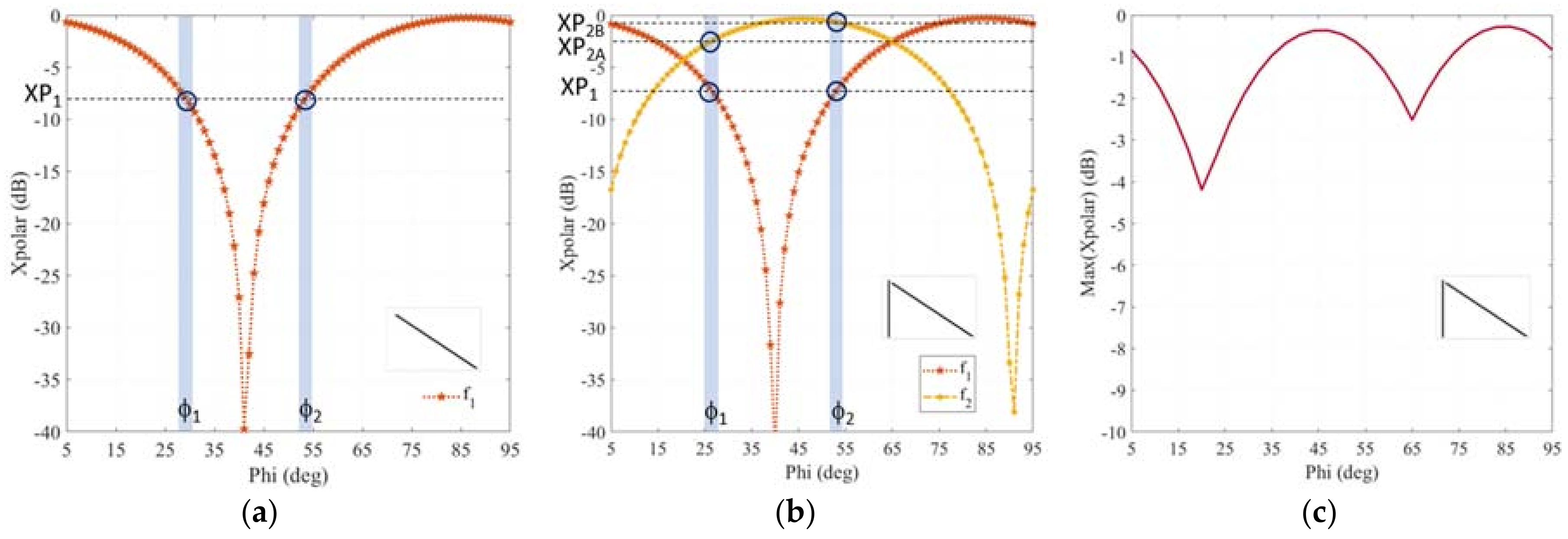
Let us focus the attention on the angular response of the single-dipole unit cell presented in (Figure 1) in correspondence to the frequency f1 = 5.25 GHz, for which the cross-polar reflected field is maximized. For the sake of simplicity, a 90-degree span is considered in this first part of the analysis, but a 180 degree span will be considered for the final performance assessment. Looking at the cross polar response of the single-dipole unit cell (Figure 2a) as a function of φ, it is apparent that there are some cases in which the magnitude of the scattered field is quite low (e.g., around 40 degrees), and above all, that in some cases two different angles exhibit the same cross polar level. For example, φ1 and φ2 both assume a value of XP1, thus causing an ambiguity in the correct estimate of rotation angle φ.
To reduce the ambiguity and increase the level of the received signal, a second dipole is added in the unit cell (inset Figure 2b). It is important to notice that the length of this dipole and its orientation is different than the initial one. In this case, the second dipole will provide the maximum of its reflected cross polar response at frequency f2 = 7.35 GHz, since the length of the two-dipole is different (Figure 2b). Therefore, if we consider again two values of φ for which the cross polar response at f1 is ambiguous, it is possible to discriminate between φ1 and φ2 since they exhibit a different cross polar value at f2, namely XP2A and XP2B. Accordingly, the rotation state of φ1 is encoded by using the couple (XP1, XP2A), whereas φ2 is represented by (XP1, XP2B). Moreover, if the maximum of the reflected cross polar field is considered (Figure 2c), it is apparent that the lowest value is around −4 dB, which can help in retrieving the correct angular rotation state. It is important to point out that only two frequencies are required by the encoding scheme, which is based on the values assumed by the cross polar at f1 and f2. However, despite the adoption of two dipoles, a certain level of ambiguity is still present due to similar values assumed by the cross polar reflection coefficient at the two reference frequencies. It is therefore essential to determine the number of elements that are requested for an unambiguous recovery of the rotation angle, as well as determine a metric for assessing the robustness of the proposed encoding mechanism.

3. Performance Assessment and Design Improvement

Let us consider the two-dipole structure reported in the inset Figure 2b. The cross polar response as a function of frequency is reported in Figure 3a for a 90-degree span of φ. As is apparent, the peak values of the cross polar are localized at two frequencies f1 and f2 (i.e., 5.25 GHz and 7.35 GHz) with very slight shifts around them. It is important to mention that even when the maximum of the cross polar is not exactly at f1 or f2, the value at those frequencies is selected. This is because there is not much difference between the real maximum and the value assumed at f1 and f2, and also due to the simplification of both the algorithm and the hardware used in the decoding. Therefore, the cross polar value at f1 and f2 is the codification of the angular position of the tag (Figure 3b).
In order to understand the reliability of a decoding process based on the values assumed by the cross polar in correspondence of a certain number of frequencies fres, it is necessary to define a distance between the coding of two different angular positions, namely φi and φj. This distance function Dist is defined as:
D i s t ( ϕ i , ϕ j ) = m = 1 f r e s ( X p o l d B ( f m , ϕ i ) X p o l d B ( f m , ϕ j ) ) 2 .
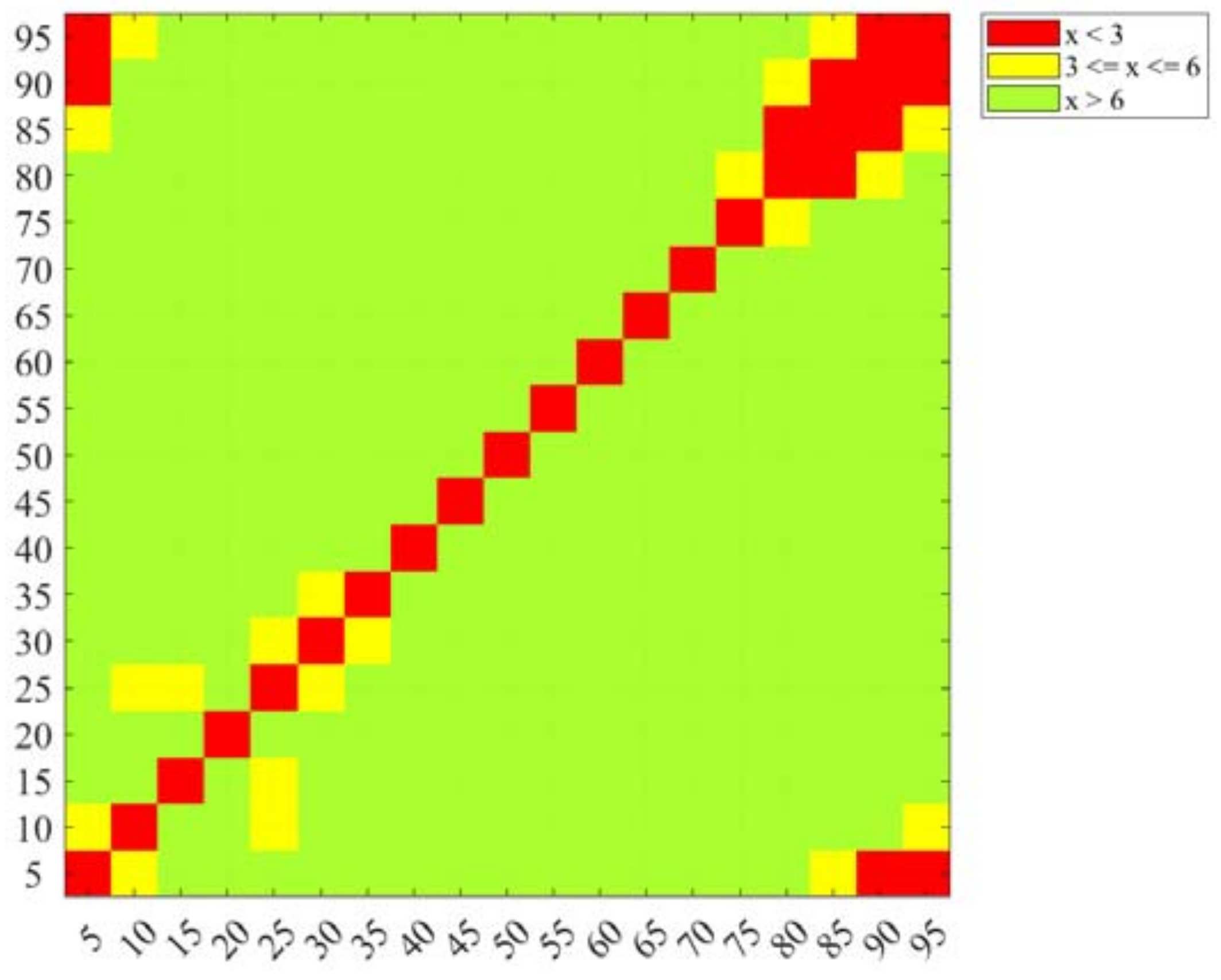
where Xpol(fm, φi) is the codification in terms of cross polar magnitude of the reflected field. Then it is possible to evaluate the distance of a codification with all the others in order to check if any ambiguity is present. Let us fix two thresholds, (thres1 and thres2), and consider two singular angular positions, namely φA and φB. If the value of Dist(φA, φB) is greater than thres1, they are unambiguously encoded. If Dist(φA, φB) is between thres1 and thres2, they are critically encoded. If Dist(φA, φB) is lower than thres2, they are not reliable. This information is clearly represented in the color map of Figure 4a for the case of the two-dipole structure. Each pixel corresponds to the distance between the two referred angular positions. It is well visible that some angle codifications are not univocally defined (such as 60 degrees and 20 degrees), because the distance between their encoding is below the imposed threshold.
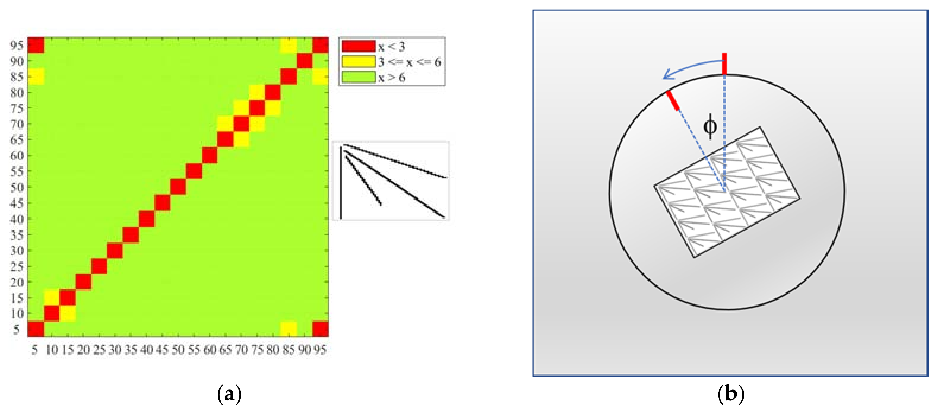
In order to improve the performance of the encoding scheme, it is necessary to increase the number of involved frequencies. The introduction of a third dipole is obviously beneficial, as illustrated in Figure 4b. The uncertainty has been considerably reduced and only angular values within the interval (55°, 80°) suffer from a certain degree of ambiguity. To remove the remaining inefficiencies a fourth dipole is added. The final result is shown in Figure 5 where almost all the encodings satisfy both the threshold levels, with just six couples of coded positions between the two; they are (10°, 15°), (65°, 70°), (70°, 75°), (75°, 80°) and (85°, 95°). The only remaining critical couple is (5°, 95°). However, if the starting position and the sense of rotation are known, the angular position can be monitored without any ambiguity since 5 degrees and 95 degrees are not contiguous values.
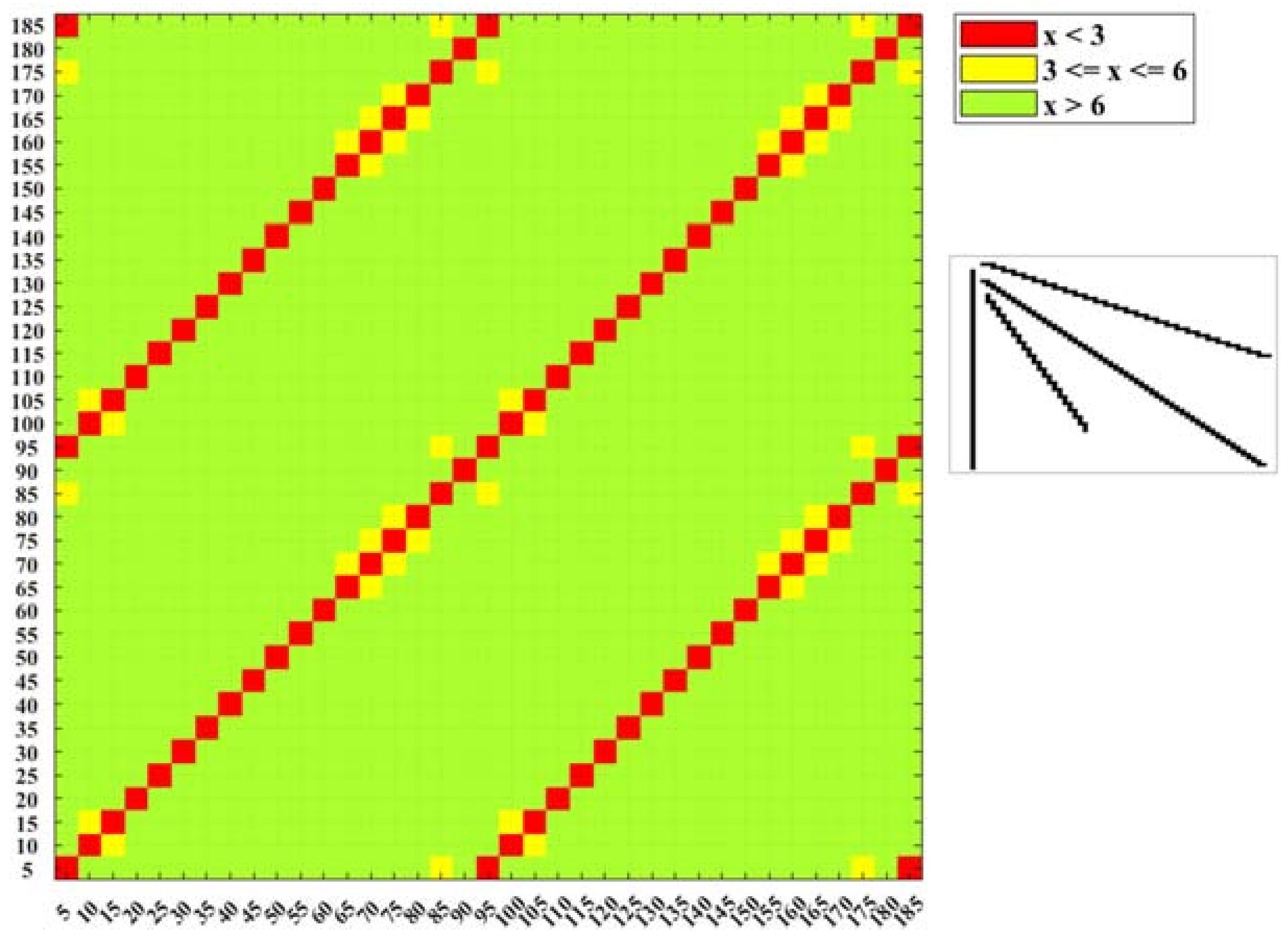
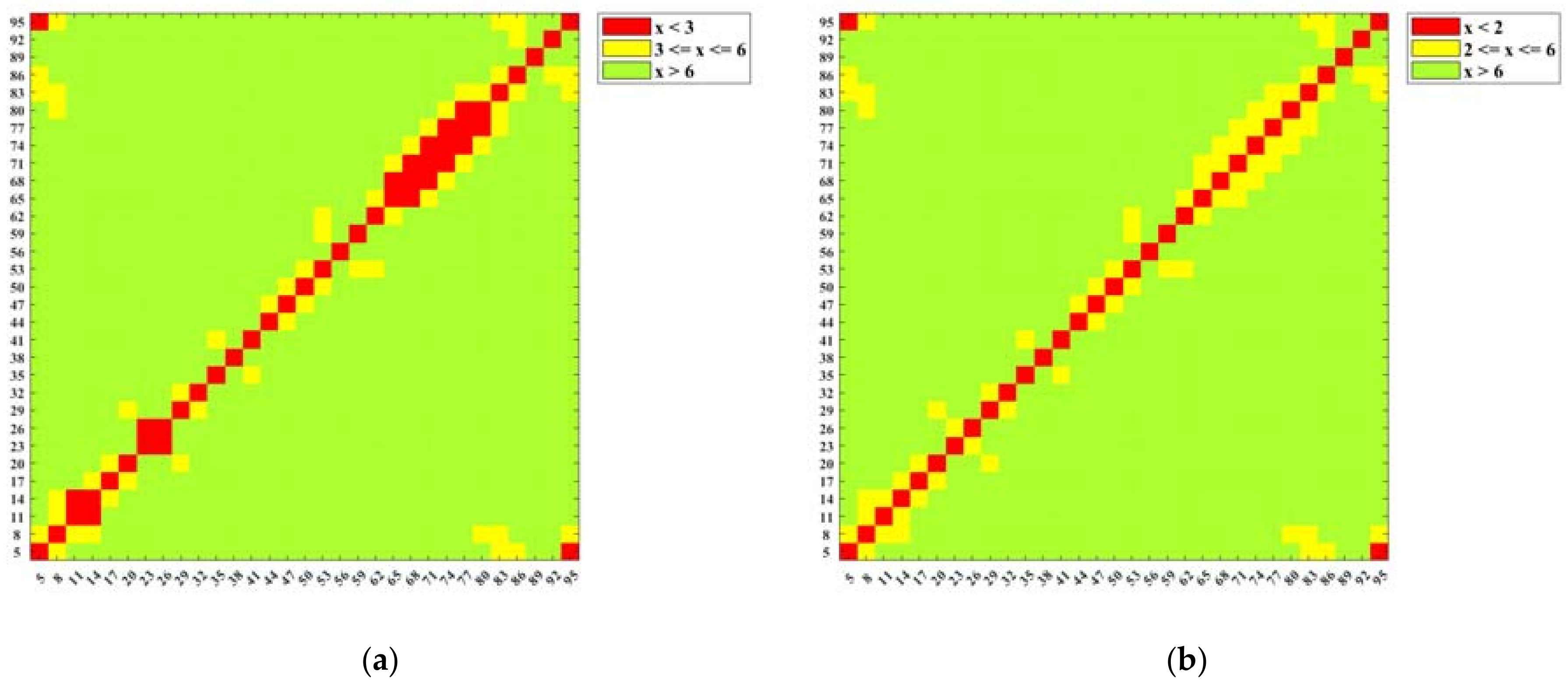
If the starting point and rotation sense are known, an angular range that spans 180 degrees can be considered successfully monitored as well (Figure 6). The resolution step of 3 degrees can also be achieved if the minimum requested distance for considering two different unambiguously coded angles (i.e., the value of thres2) is set equal to 2 dB (Figure 7).
It is important to underline that if both the reference and the sense of rotation are known, the proposed chipless RFID tag can potentially monitor the angular position of an object with a resolution of up to 5 degrees, by using four fixed frequencies.

4. Measurements

A prototype of the sensor has been manufactured (Figure 8) and tested. The measurements have been performed, by using a two-port Vector Network Analyzer (Keysight—E5071C) and a dual-polarized horn antenna (Flann DP240), placed 40 cm from the tag. The tag has been rotated manually every 5 degrees. The cross polar backscattering is represented by the measured S21. This signal contains the response of the tag as well as the response of the environment. For this reason, the measured raw signal has been improved, by subtracting the environment response ( S c r o s s t a g = S 21 t a g S 21 t a g ) . The cleaned signal S c r o s s t a g , measured for all of the azimuthal angles has been used to generate a map similar to the one already obtained by using the simulated data.
The chart mapping the distance among the encodings of the different angular positions obtained by using the measurements is illustrated in Figure 9. It is apparent that the map measurements agree to simulated data (Figure 5), with the only exception being angular positions close to 90 degrees. This small discrepancy could be due to some errors in the alignment with the angular reference positions or the non-perfect orthogonality between the antenna and the tag axes. Theoretically, the rotation speed is not an issue for the monitoring process. In practice, for typical rotation speeds of wind generators (5–20 rpm) or robotic arms, even a non-dedicated hardware and software platform can provide the reading. For very high rotation speeds (drilling machines or turbines), the data acquisition may require a dedicated hardware and software platform in order to guarantee real-time measurements.

5. Conclusions

A novel chipless RFID sensor for monitoring the angular position of a rotating object has been presented in this paper. The rotation state is encoded in the cross polar response of a tag, based on a truncated periodic surface, composed of a set of dipoles. The adopted cross polarization response allows the achievement of a reliable response even if it the chipless RFID sensor is applied on metallic objects or in an environment with strong multipath. The proposed passive sensor needs only a small set of reading frequencies that depend on the number of employed dipoles. A manufactured prototype has been experimentally characterized and a good agreement between simulations and measurements has been found.

Author Contributions

Conceptualization: S.G., F.C. and M.B.; Methodology, S.G., F.C., M.B., F.A.D. and G.M.; Software, S.G., F.C. and M.B.; Validation, S.G., F.C., M.B., F.A.D.; Writing-Original Draft Preparation, S.G.; Writing-Review & Editing, S.G., F.C., M.B., F.A.D. and G.M.; Funding Acquisition, G.M., S.G. and F.C.

Funding

This research was partially funded by H2020 Programme, Call MSCA-RISE-2014, Project EMERGENT, GA n. 645771.

Acknowledgments

The authors would like to thank David Girbau Sala and Antonio Ramon Lázaro Guillén at the Eng. Electrònica, Elèctrica i Automàtica Universitat Rovira i Virgili, Spain as well as Smail Tedjini at the Laboratoire de Conception et d’Intégration des Systèmes (LCIS), Grenoble-INP, Université Grenoble-Alpes, France for their useful technical discussions and comments. The authors are also grateful to the Additive Manufacturing CrossLab (https://crosslab.dii.unipi.it/additive-manufacturing-lab) for partially supporting this project.

Conflicts of Interest

The authors declare no conflict of interest.

References

  1. Finkenzeller, K. Fundamentals and Applications in Contactless Smart Cards, Radio Frequency Identification and Near-Field Communication, 3rd ed.; Wiley: Chichester, UK; Hoboken, NJ, USA, 2010. [Google Scholar]
  2. Angeles, R. Rfid Technologies: Supply-Chain Applications and Implementation Issues. Inf. Syst. Manag. 2005, 22, 51–65. [Google Scholar] [CrossRef]
  3. Liu, G.; Mao, L.; Chen, L.; Xie, S. Locatable-Body Temperature Monitoring Based on Semi-Active UHF RFID Tags. Sensors 2014, 14, 5952–5966. [Google Scholar] [CrossRef] [PubMed] [Green Version]
  4. Vaz, A.; Ubarretxena, A.; Zalbide, I.; Pardo, D.; Solar, H.; Garcia-Alonso, A.; Berenguer, R. Full Passive UHF Tag With a Temperature Sensor Suitable for Human Body Temperature Monitoring. IEEE Trans. Circuits Syst. II Express Briefs 2010, 57, 95–99. [Google Scholar] [CrossRef]
  5. Ramos, A.; Clement, P.; Lazaro, A.; Llobet, E.; Girbau, D. Nitrogen Dioxide Wireless Sensor Based on Carbon Nanotubes and UWB RFID Technology. IEEE Antennas Wirel. Propag. Lett. 2015, 14, 1145–1148. [Google Scholar] [CrossRef]
  6. Vyas, R.; Lakafosis, V.; Lee, H.; Shaker, G.; Yang, L.; Orecchini, G.; Traille, A.; Tentzeris, M.M.; Roselli, L. Inkjet Printed, Self Powered, Wireless Sensors for Environmental, Gas, and Authentication-Based Sensing. IEEE Sens. J. 2011, 11, 3139–3152. [Google Scholar] [CrossRef] [Green Version]
  7. Occhiuzzi, C.; Marrocco, G. Human body sensing: A pervasive approach by implanted RFID tags. In Proceedings of the 2010 3rd International Symposium on Applied Sciences in Biomedical and Communication Technologies (ISABEL 2010), Rome, Italy, 7–10 November 2010; pp. 1–5. [Google Scholar]
  8. Jiang, Z.; Fu, Z.; Yang, F. RFID tag antenna based wireless sensing method for medical transfusion applications. In Proceedings of the 2012 IEEE International Conference on RFID-Technologies and Applications (RFID-TA), Nice, France, 5–7 November 2012; pp. 126–130. [Google Scholar]
  9. Leon-Salas, W.D.; Halmen, C. A RFID Sensor for Corrosion Monitoring in Concrete. IEEE Sens. J. 2016, 16, 32–42. [Google Scholar] [CrossRef]
  10. Zhang, J.; Tian, G.; Marindra, A.; Sunny, A.; Zhao, A. A Review of Passive RFID Tag Antenna-Based Sensors and Systems for Structural Health Monitoring Applications. Sensors 2017, 17, 265. [Google Scholar] [CrossRef] [PubMed]
  11. Buffi, A.; Nepa, P.; Lombardini, F. A Phase-Based Technique for Localization of UHF-RFID Tags Moving on a Conveyor Belt: Performance Analysis and Test-Case Measurements. IEEE Sens. J. 2015, 15, 387–396. [Google Scholar] [CrossRef]
  12. Krigslund, R.; Dosen, S.; Popovski, P.; Dideriksen, J.L.; Pedersen, G.F.; Farina, D. A Novel Technology for Motion Capture Using Passive UHF RFID Tags. IEEE Trans. Biomed. Eng. 2013, 60, 1453–1457. [Google Scholar] [CrossRef] [PubMed] [Green Version]
  13. Bhattacharyya, R.; Floerkemeier, C.; Sarma, S. Low-Cost, Ubiquitous RFID-Tag-Antenna-Based Sensing. Proc. IEEE 2010, 98, 1593–1600. [Google Scholar] [CrossRef]
  14. Ruiz-Garcia, L.; Lunadei, L.; Barreiro, P.; Robla, I. A Review of Wireless Sensor Technologies and Applications in Agriculture and Food Industry: State of the Art and Current Trends. Sensors 2009, 9, 4728–4750. [Google Scholar] [CrossRef] [PubMed] [Green Version]
  15. Potyrailo, R.A.; Nagraj, N.; Tang, Z.; Mondello, F.J.; Surman, C.; Morris, W. Battery-free Radio Frequency Identification (RFID) Sensors for Food Quality and Safety. J. Agric. Food Chem. 2012, 60, 8535–8543. [Google Scholar] [CrossRef] [PubMed]
  16. Costa, F.; Genovesi, S.; Monorchio, A. A Chipless RFID Based on Multiresonant High-Impedance Surfaces. IEEE Trans. Microw. Theory Tech. 2013, 61, 146–153. [Google Scholar] [CrossRef]
  17. Vena, A.; Perret, E.; Tedjini, S. Design of Compact and Auto-Compensated Single-Layer Chipless RFID Tag. IEEE Trans. Microw. Theory Tech. 2012, 60, 2913–2924. [Google Scholar] [CrossRef]
  18. Chamarti, A.; Varahramyan, K. Transmission Delay Line Based ID Generation Circuit for RFID Applications. IEEE Microw. Wirel. Compon. Lett. 2006, 16, 588–590. [Google Scholar] [CrossRef]
  19. Harma, S.; Arthur, W.G.; Hartmann, C.S.; Maev, R.G.; Plessky, V.P. Inline SAW RFID tag using time position and phase encoding. IEEE Trans. Ultrason. Ferroelectr. Freq. Control 2008, 55, 1840–1846. [Google Scholar] [CrossRef] [PubMed]
  20. Genovesi, S.; Costa, F.; Monorchio, A.; Manara, G. Chipless RFID Tag Exploiting Multifrequency Delta-Phase Quantization Encoding. IEEE Antennas Wirel. Propag. Lett. 2016, 15, 738–741. [Google Scholar] [CrossRef]
  21. Balbin, I.; Karmakar, N.C. Phase-Encoded Chipless RFID Transponder for Large-Scale Low-Cost Applications. IEEE Microw. Wirel. Compon. Lett. 2009, 19, 509–511. [Google Scholar] [CrossRef]
  22. Costa, F.; Genovesi, S.; Monorchio, A. Chipless RFIDs for Metallic Objects by Using Cross Polarization Encoding. IEEE Trans. Antennas Propag. 2014, 62, 4402–4407. [Google Scholar] [CrossRef]
  23. Vena, A.; Perret, E.; Tedjini, S. A compact chipless RFID tag using polarization diversity for encoding and sensing. In Proceedings of the 2012 IEEE International Conference on RFID (RFID), Orlando, FL, USA, 3–5 April 2012; pp. 191–197. [Google Scholar]
  24. Borgese, M.; Dicandia, F.A.; Costa, F.; Genovesi, S.; Manara, G. An Inkjet Printed Chipless RFID Sensor for Wireless Humidity Monitoring. IEEE Sens. J. 2017, 17, 4699–4707. [Google Scholar] [CrossRef] [Green Version]
  25. Sauer, S.; Fischer, W.-J. A Passive Wireless Humidity Threshold Monitoring Sensor Principle Based on Deliquescent Salts and a Diffusion Based Irreversible State Change. IEEE Sens. J. 2014, 14, 971–978. [Google Scholar] [CrossRef]
  26. Nair, R.S.; Perret, E.; Tedjini, S.; Baron, T. A Group-Delay-Based Chipless RFID Humidity Tag Sensor Using Silicon Nanowires. IEEE Antennas Wirel. Propag. Lett. 2013, 12, 729–732. [Google Scholar] [CrossRef]
  27. Schussler, M.; Kohler, C.; Wiens, A.; Kubina, B.; Mandel, C.; Friedrich, A.; Binder, J.; Jakoby, R. Screen printed chipless wireless temperature sensor tag based on Barium Strontium Titanate thick film capacitor. In Proceedings of the 2014 IEEE SENSORS, Valencia, Spain, 2–5 November 2014; pp. 2223–2226. [Google Scholar]
  28. Vena, A.; Sydänheimo, L.; Tentzeris, M.M.; Ukkonen, L. A Fully Inkjet-Printed Wireless and Chipless Sensor for CO2 and Temperature Detection. IEEE Sens. J. 2015, 15, 89–99. [Google Scholar] [CrossRef]
  29. Pöpperl, M.; Adametz, J.; Vossiek, M. Extremely temperature-resistant, polarimetric radar barcode. In Proceedings of the 2017 47th European Microwave Conference (EuMC), Nuremberg, Germany, 10–12 October 2017; pp. 97–100. [Google Scholar]
  30. Horestani, A.K.; Abbott, D.; Fumeaux, C. Rotation Sensor Based on Horn-Shaped Split Ring Resonator. IEEE Sens. J. 2013, 13, 3014–3015. [Google Scholar] [CrossRef]
  31. Ebrahimi, A.; Withayachumnankul, W.; Al-Sarawi, S.F.; Abbott, D. Metamaterial-Inspired Rotation Sensor with Wide Dynamic Range. IEEE Sens. J. 2014, 14, 2609–2614. [Google Scholar] [CrossRef]
  32. Sipal, V.; Narbudowicz, A.Z.; Ammann, M.J. Contactless Measurement of Angular Velocity Using Circularly Polarized Antennas. IEEE Sens. J. 2015, 15, 3459–3466. [Google Scholar] [CrossRef] [Green Version]
  33. Matbouly, H.E.; Zannas, K.; Duroc, Y.; Tedjini, S. Analysis and Assessments of Time Delay Constrains for Passive RFID Tag-Sensor Communication Link: Application for Rotation Speed Sensing. IEEE Sens. J. 2017, 17, 2174–2181. [Google Scholar] [CrossRef]
  34. Genovesi, S.; Costa, F.; Borgese, M.; Monorchio, A.; Manara, G. Chipless RFID tag exploiting cross polarization for angular rotation sensing. In Proceedings of the 2016 IEEE International Conference on Wireless for Space and Extreme Environments (WiSEE), Aachen, Germany, 26–28 September 2016; pp. 158–160. [Google Scholar]
  35. Genovesi, S.; Costa, F.; Borgese, M.; Dicandia, F.A.; Monorchio, A.; Manara, G. Chipless RFID sensor for rotation monitoring. In Proceedings of the 2017 IEEE International Conference on RFID Technology Application (RFID-TA), Warsaw, Poland, 20–22 September 2017; pp. 233–236. [Google Scholar]
  36. Mata-Contreras, J.; Herrojo, C.; Martín, F. Application of Split Ring Resonator (SRR) Loaded Transmission Lines to the Design of Angular Displacement and Velocity Sensors for Space Applications. IEEE Trans. Microw. Theory Tech. 2017, 65, 4450–4460. [Google Scholar] [CrossRef] [Green Version]
  37. Borgese, M.; Costa, F.; Genovesi, S.; Monorchio, A.; Manara, G. Multi-frequency polarizarition converter with enhanced angular robustness. In Proceedings of the 2016 IEEE International Symposium on Antennas and Propagation (APSURSI), Fajardo, Puerto Rico, 26 June–1 July 2016; pp. 669–670. [Google Scholar]
  38. Costa, F.; Gentile, A.; Genovesi, S.; Buoncristiani, L.; Lazaro, A.; Villarino, R.; Girbau, D. A Depolarizing Chipless RF Label for Dielectric Permittivity Sensing. IEEE Microw. Wirel. Compon. Lett. 2018, 28, 371–373. [Google Scholar] [CrossRef]
  39. Mandel, C.; Jiménez-Sáez, A.; Polat, E.; Schüßler, M.; Kubina, B.; Scherer, T.; Lautenschläger, N.; Jakoby, R. Dielectric ring resonators as chipless temperature sensors for wireless machine tool monitoring. In Proceedings of the 2017 11th European Conference on Antennas and Propagation (EUCAP), Paris, France, 19–24 March 2017; pp. 3912–3916. [Google Scholar]
  40. Costa, F.; Borgese, M.; Gentile, A.; Buoncristiani, L.; Genovesi, S.; Dicandia, F.A.; Bianchi, D.; Monorchio, A.; Manara, G. Robust Reading Approach for Moving Chipless RFID Tags by Using ISAR Processing. IEEE Trans. Microw. Theory Techn. 2018, 66, 2442–2451. [Google Scholar] [CrossRef]
  41. Mittra, R.; Chan, C.H.; Cwik, T. Techniques for analyzing frequency selective surfaces—A review. Proc. IEEE 1988, 76, 1593–1615. [Google Scholar] [CrossRef]
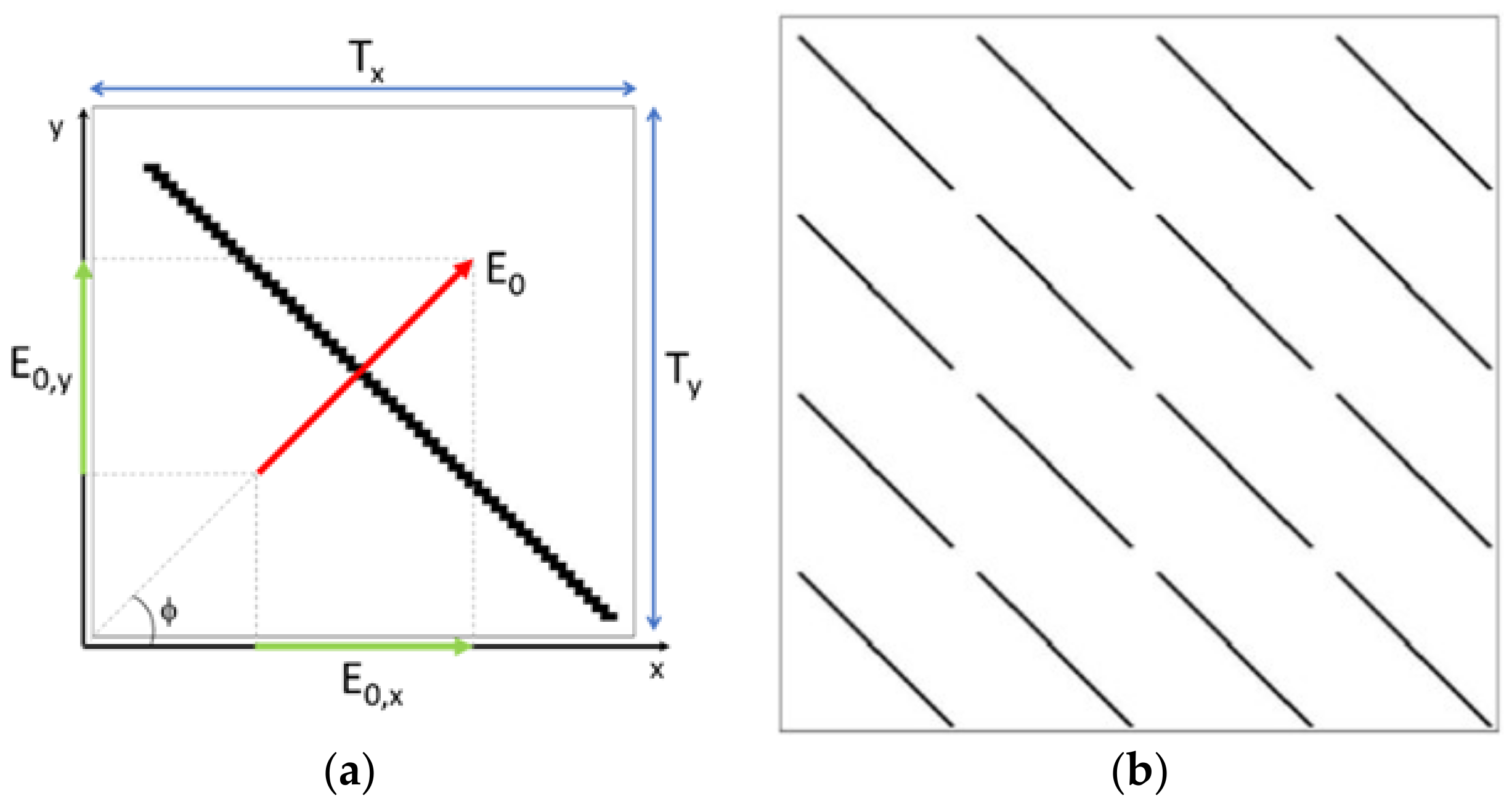
Figure 1. Example of a unit cell of the periodic surface employed for the design of the chipless RFID sensor: (a) A unit cell with a dipole element and (b) the correspondent finite chipless RFID sensor tag with 4 × 4 unit cells.
Technologies 06 00061 g001
Figure 2. Cross polar response of the tested structures (shown in the insets): (a) Single-dipole; (b) two dipoles; (c) maximum level of the cross polar for the two-dipole case. The employed dielectric has a permittivity εr =2.8 − j0.003 and thickness equal to 1.5 mm, whereas the periodicity values are Tx = 1.7 cm and Ty = 1.5 cm.
Technologies 06 00061 g002
Figure 3. (a) Cross polar of the two-dipole structure at 5-degree steps within a 90-degree span of φ, and (b) the correspondent values for each angular position at f1 and f2.
Technologies 06 00061 g003
Figure 4. (a) Chart mapping the distance for the two-dipole structure, and (b) three-dipole structure. The three quantized levels of x = Dist(φA, φB) refer to the value assumed by the cross polar at f1 and f2 and by considering thres1 = 6 dB and thres2 = 3 dB. The unit cell is shown in the respective insets.
Technologies 06 00061 g004
Figure 5. (a) Chart mapping the distance for the four-dipole structure: the three quantized levels of x = Dist(φA, φB) refer to the value assumed by the cross polar at f1 and f2 and by considering thres1 = 6 dB and thres2 = 3 dB. The unit cell is shown in the respective inset; (b) example of application of a 4 × 4 chipless RFID tag with four dipoles applied to a rotating object with a known reference for monitoring the counterclockwise rotation.
Technologies 06 00061 g005
Figure 6. Chart mapping the distance for the four-dipole structure when the considered angular interval spans 180 degrees.
Technologies 06 00061 g006
Figure 7. (a) Chart mapping the distance for the four-dipole structure when the value of thres2 is set equal to 3 dB and when (b) it is 2 dB. Resolution step of 3 degrees.
Technologies 06 00061 g007
Figure 8. Prototype of the chipless RFID sensor for angular rotation monitoring comprising a set of 4 × 4 unit cells with four-dipole elements in each one.
Technologies 06 00061 g008
Figure 9. Chart mapping the distance for the four-dipole structure obtained by measured data.
Technologies 06 00061 g009