1. Introduction
Selective laser melting (SLM) is one of the additive manufacturing (AM) processes that produces highly-complex three-dimensional structures directly from computer-aided design (CAD). It was developed in the late 1980s from the selective laser sintering process, which was first described by Bourell et al. [
1]. SLM is a layer-by-layer process, which is repeated iteratively until the desired part is finished [
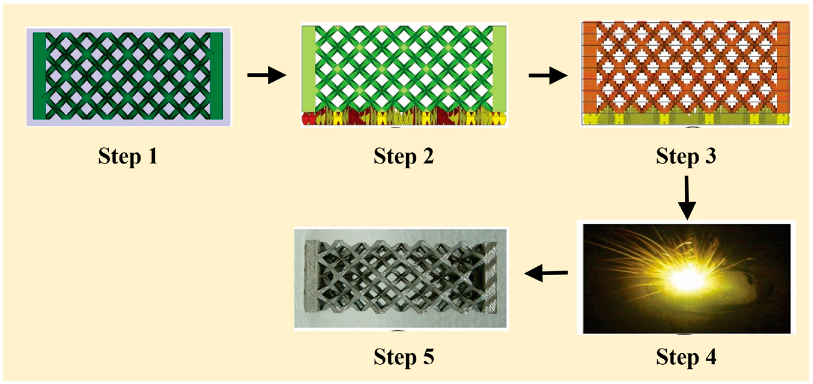
2]. The SLM process chain involves five major steps, from the creation of the CAD file to having the final fabricated part: (1) design and generation of an appropriate CAD file that exactly resembles the part to be produced; (2) orientation of the part with respect to the substrate plate and the design of support structures between the part and the substrate plate. The support structures are introduced between the sample and the substrate, aiding for the easy removal of the part after fabrication from the substrate plate; (3) slicing of the absolute data into individual layers depending on the layer thickness, and applying the process parameters, such as laser power, laser scanning speed, hatch distance, hatch style, etc., are applied; (4) actual melting of the part; and (5) removal of the part from the substrate plate and detachment of the support structures. This process chain is described in detailed by Löber et al. [
3] (
Figure 1).
The SLM process can manufacture fully-dense parts without the need of post-processes, such as infiltration, sintering, and hot-isostatic pressing. In addition, theoretically, any geometry can be built with this technique. The technology allows a design-focused manufacturing process and enables the possibility to manufacture small lot sizes with a high degree of product customization, even on an industrial production scale [
4]. Disadvantages of the SLM process arise from high manufacturing costs due to expensive production of appropriate powder material with narrow particle size distribution. In addition, the SLM process requires a longer processing time to produce a sample compared to conventional production methods. The build time of a part is mainly defined by the volume and the height of the part, since it is a layer-by-layer-based process [
5]. Therefore, the design and manufacturing of lightweight parts with interior cellular lattice structures are desired to save expensive functional materials, and reduce the build time and energy consumption in the SLM process. Furthermore, cellular lattice structures can offer special mechanical and thermal properties, such as high specific strength, high specific stiffness, good energy absorption characteristics, and good thermal insulation, which makes them interesting for medical and aerospace applications [
6,
7].
Weinans et al. [
8] claims that the main objective for lattice structures in the aerospace sector is to create lightweight structures consisting of stiff skins and truss cores; in the biomedical sector bone-like structures with adapted strength and elastic modulus close to the one of bones to reduce the stress-shielding effect are desired [
8]. Today, metal foams are already in use for biomedical applications [
9]. However, stochastic geometry of foams lead to unpredictability in their mechanical properties on the local scale. The mechanical properties of the manufactured parts depend on the type and distribution of unit-cells and on the relative density. Thus, the knowledge of cellular structure properties is required to obtain parts with desired mechanical properties. The low stiffness and strength of open-cell metal foams has generated significant interest in alternative cell topologies, which might offer strengths comparable to honeycombs while simultaneously facilitating the other functionalities of open-cell metal foams [
10].
Accordingly, in this work, we present the mechanical properties of an open-cell rhombic dodecahedron cellular structure. The unit cell of the structure is a space-filling convex polyhedron called a rhombic dodecahedron (also called a rhomboidal dodecahedron). The unit cell has 12 identical rhombic faces with 24 edges and 14 vertices. Each face of a rhombic dodecahedron is a rhombus, with angles of 2α = 2cot−1√2 ≈ 70.53° and 2θ = 2tan−1√2 ≈ 109.47°. Cellular structures with a similar structural organization can be observed in nature and honeybees use the geometry of a rhombic dodecahedron to form a honeycomb from a tessellation of cells, each of which is a hexagonal prism capped with half a rhombic dodecahedron. This structure is especially well suited to production using the selective laser melting process and, when placed properly, almost no support structure is needed for its production which, in turn, reduces the amount of material used and, hence, reduces the overall costs.
2. Experimental Section
The gas-atomized AISI 316L steel powder (from SLM solutions GmbH, Lübeck, Germany) is used for the production of the SLM samples. A SLM 250HL from SLM Solutions GmbH, equipped with a 400 W Nd-YAG laser (wave length ~1074 nm) is used for fabricating the 316L specimens. The spot size of the laser in the focus is around 80 µm in diameter. A layer thickness of 30 µm was used with the following process parameters: laser power of 175 W and a laser scanning speed of 650 mm/s for the volume, and a laser power of 100 W and a scanning speed of 800 mm/s for the outer contour. A straight line stripe-like pattern with a stripe width of 5 mm was used as the scanning strategy, with a distance of 0.012 mm between the hatches (refer to [
11] for the schematics of a stripe-like pattern with rotation between two layers). The hatches have a 73° rotation between two layers and the melting process was carried out under an argon atmosphere to avoid any possible oxygen contamination during the process [
12]. The amount of oxygen is kept below 200 ppm during the entire melting process and the atmosphere of the building chamber was set to an overpressure of 10–15 mbar.
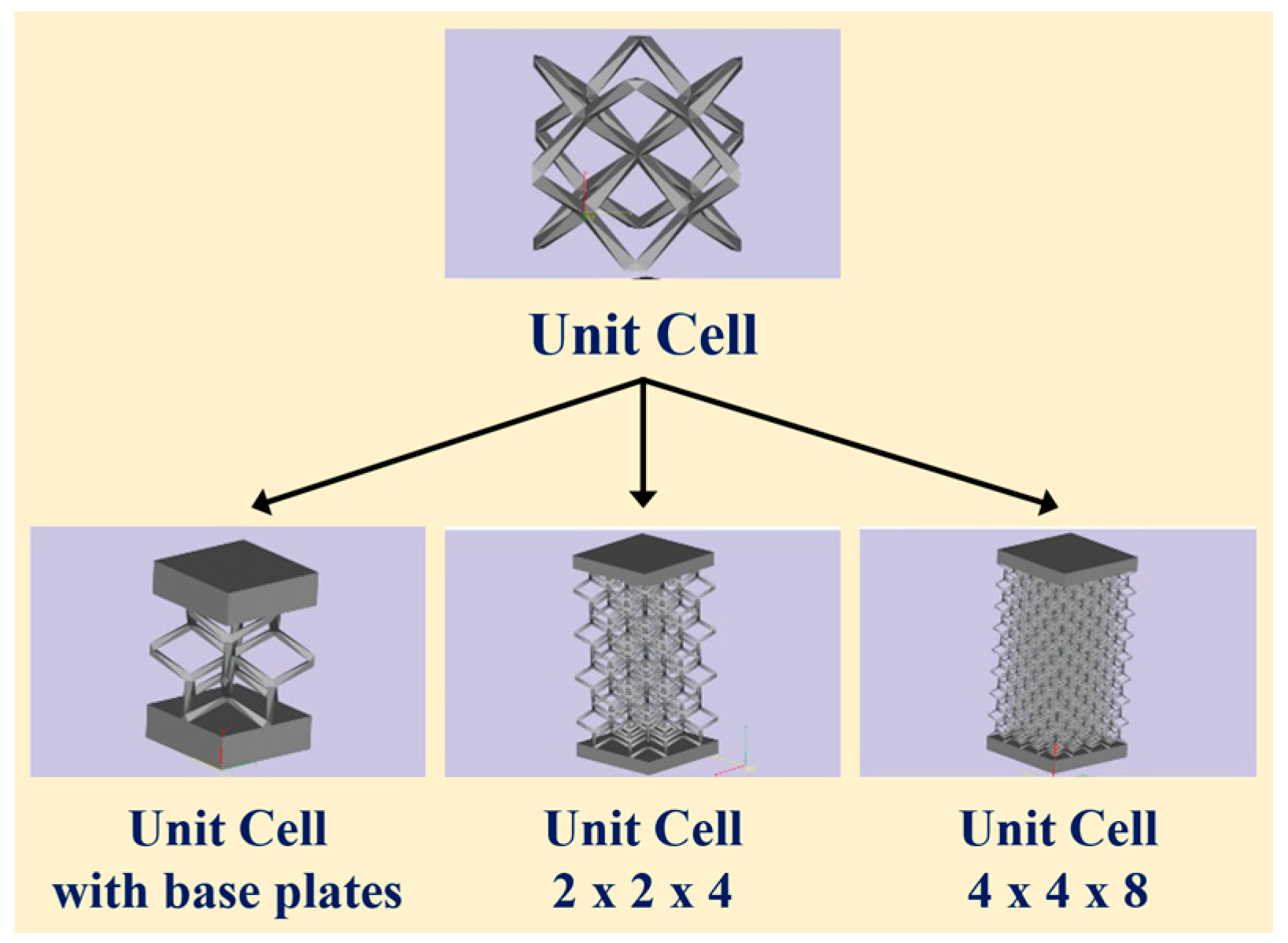
All of the parts are built in the same orientation with respect to the substrate plate, as shown in
Figure 1. Four different geometries were designed with the following specifications: a single unit cell with a 10 mm edge length; a single-unit cell, also with a 10 mm edge length, with the addition of 3 mm thick base plates; a sandwich structure with 2 × 2 × 4 unit cells with an edge length of 10 mm and base plates (referred to as 2 × 2 × 4 hereafter); and a sandwich structure with 4 × 4 × 8 unit cells with an edge length of 5 mm and base plates (referred to as 4 × 4 × 8 hereafter). Three different relative densities were realized with each of the four geometries: 4%, 12%, and 24%, respectively. Three samples in each geometry were built under the same conditions (see
Figure 2). Additionally, cylindrical reference samples were built for metallographic and structural investigation and chemical analysis. The cylinders were embedded into epoxy resin, and ground and polished with a Rotopol device from the Struers for metallographic investigation. The samples were subsequently etched with V2A etchant (100 mL HCl, 100 mL H
2O, 10 mL HNO
3 and 1 mL restrainer) at 333 K for 2 min. The microstructural investigation was carried out using a LEO Gemini SEM (Gemini, Göttingen, Germany) from Carl-Zeiss. X-ray diffraction (XRD) was performed on cut-off slices from the cylinders, which were ground with 2500 and 4000 grit grinding papers and were cleaned with ethanol. Gas-atomized powders were also tested for their structural information using XRD. Structural characterization was performed by X-ray diffraction using a D3290 PANalyticalX’pert PRO with Co-Kα radiation (λ = 0.17889 nm) in Bragg-Brentano configuration (PANalytical, Kassel-Waldau, Germany). The produced lattice structures were mechanically tested with an Instron 8562 device (Instron, Darmstadt, Germany). The base plates of the samples sometimes displayed a slight angle. To guarantee a homogenous load distribution, co-planarity between the base plates are maintained by grinding them. The deformation speed was set to 10
−3 mm/s. The compressive behavior was recorded with a digital camera from Pentax at defined deformation levels. Three-dimensional finite element simulations (quasi-static conditions) were performed using the standard software package ABAQUS [
13] (Dassault Systems, Dresden, Germany)with the use of both eight-node continuum and two-node beam elements to represent the stain distribution within the struts and the struts in the unit cells, respectively.
3. Results and Discussion
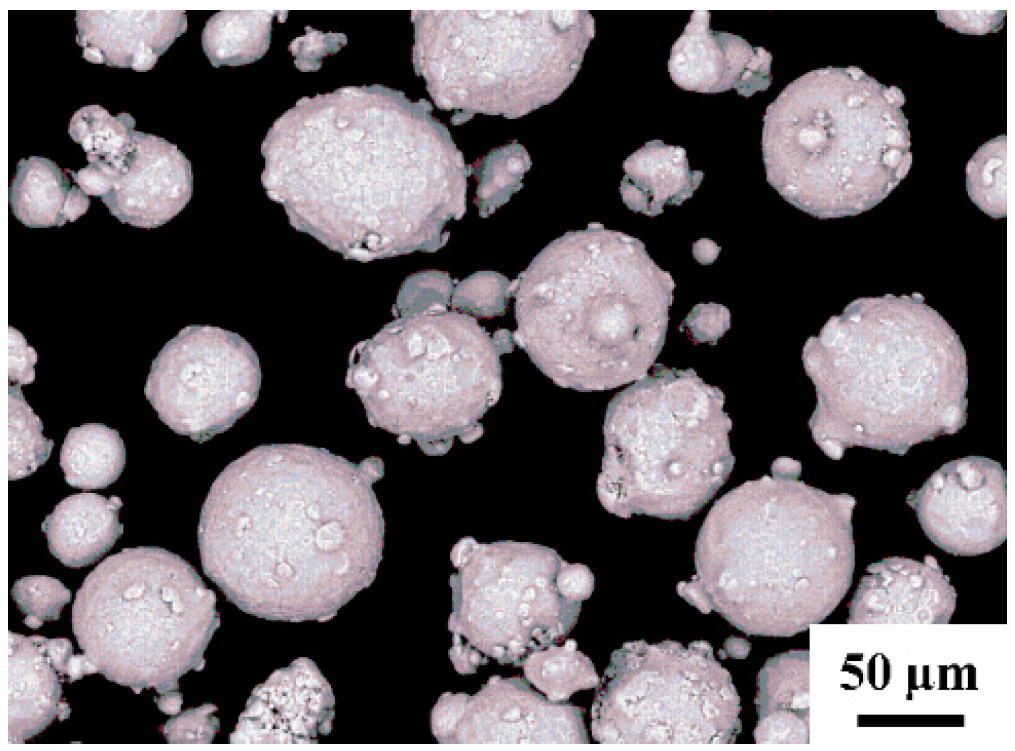
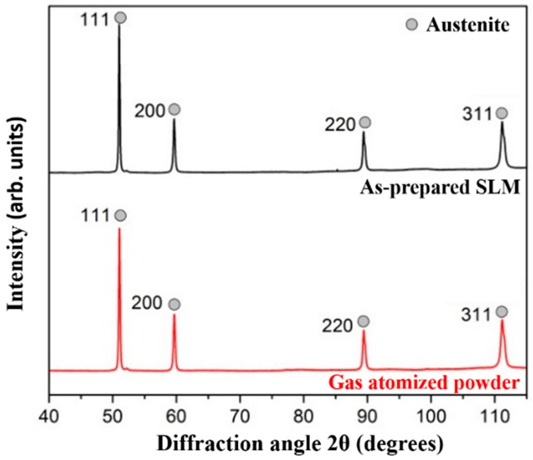
The gas-atomized powder shown in
Figure 3 is almost spherical with few satellites attached along their surface, which provides good flowability. The maximum powder particle size is ~45 µm, while most of the powder particles fall in the range 10–25 µm. The smaller powder particles (<10 µm) were removed to decrease the affinity for agglomeration and, thus, to improve the flowability of the powder. The gas atomized powder shows a fully austenitic microstructure and the same is expected from the samples after SLM. The XRD results in
Figure 4 confirms the presence of a fully austenitic microstructure (with all of the predominant peaks corresponding to the face-centered γ-phase) in both gas-atomized powder and as-prepared SLM samples.
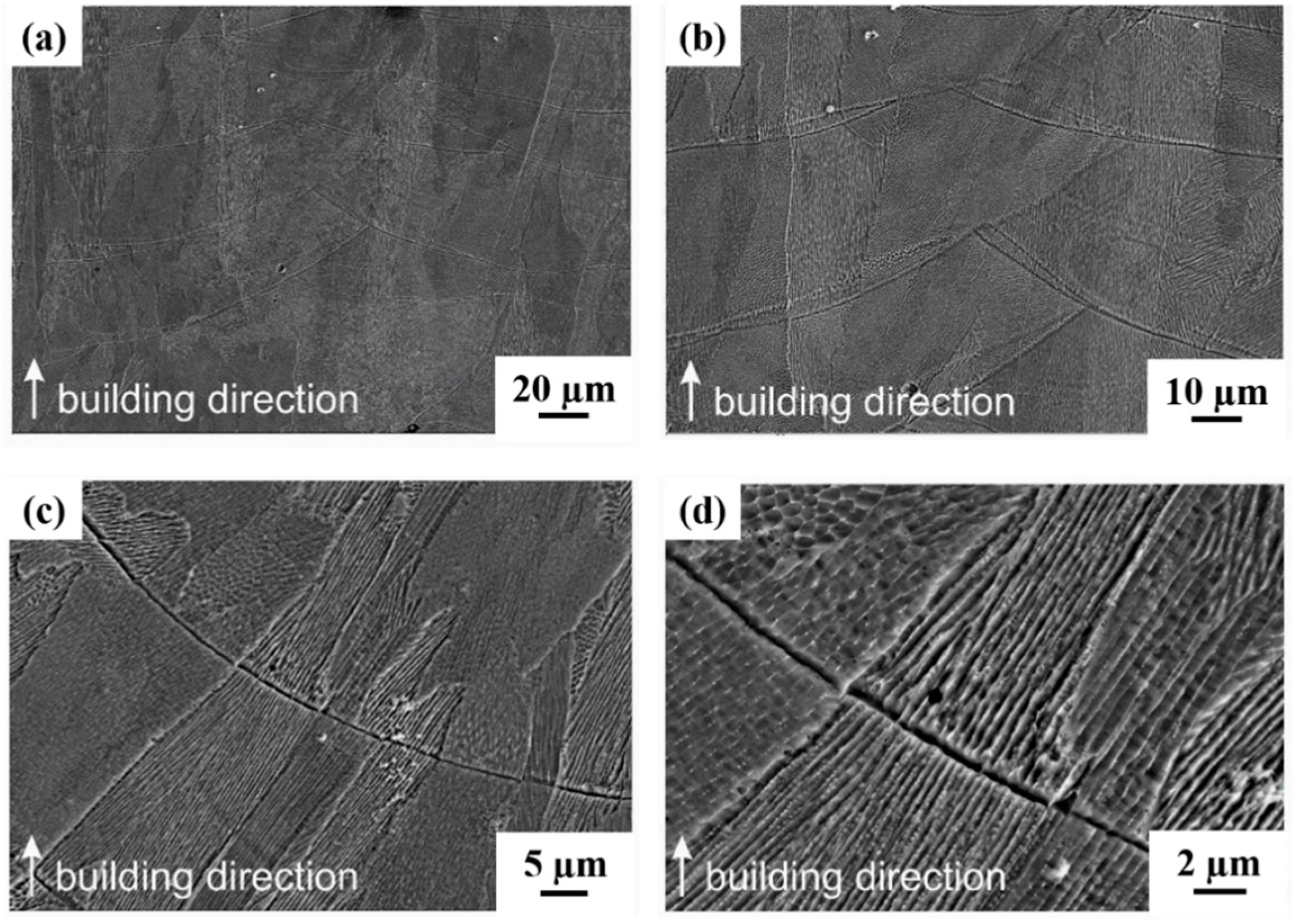
The microstructure of the 316L sample fabricated by selective laser melting is shown in
Figure 5. It displays a fine cellular/dendritic structure, similar to most of the samples prepared by SLM during to the fast cooling rates observed during the process [
14,
15,
16,
17,
18,
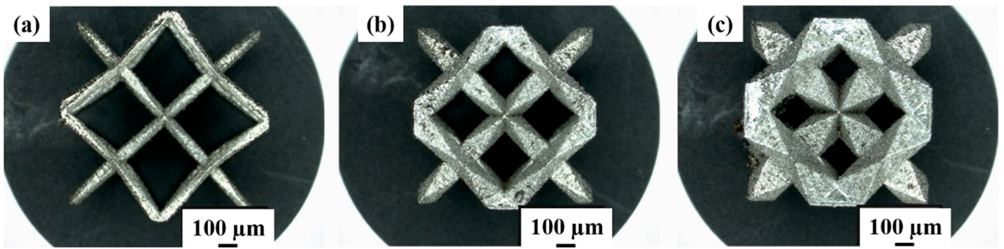
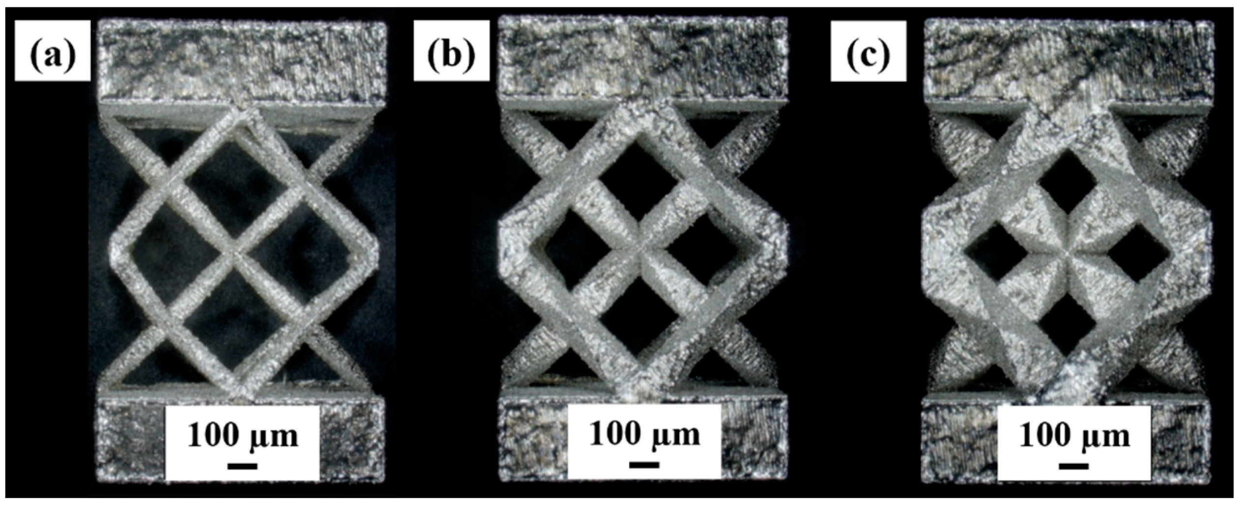
19]. This also explains the microstructural differences between the SLM prepared and conventionally cast/powder metallurgical microstructures. The SLM-produced single-unit cells and the unit cells with base plates with the three different relative densities are displayed in
Figure 6 and
Figure 7. The images can easily show the variation in the strut diameters between the samples to vary the density of the samples.
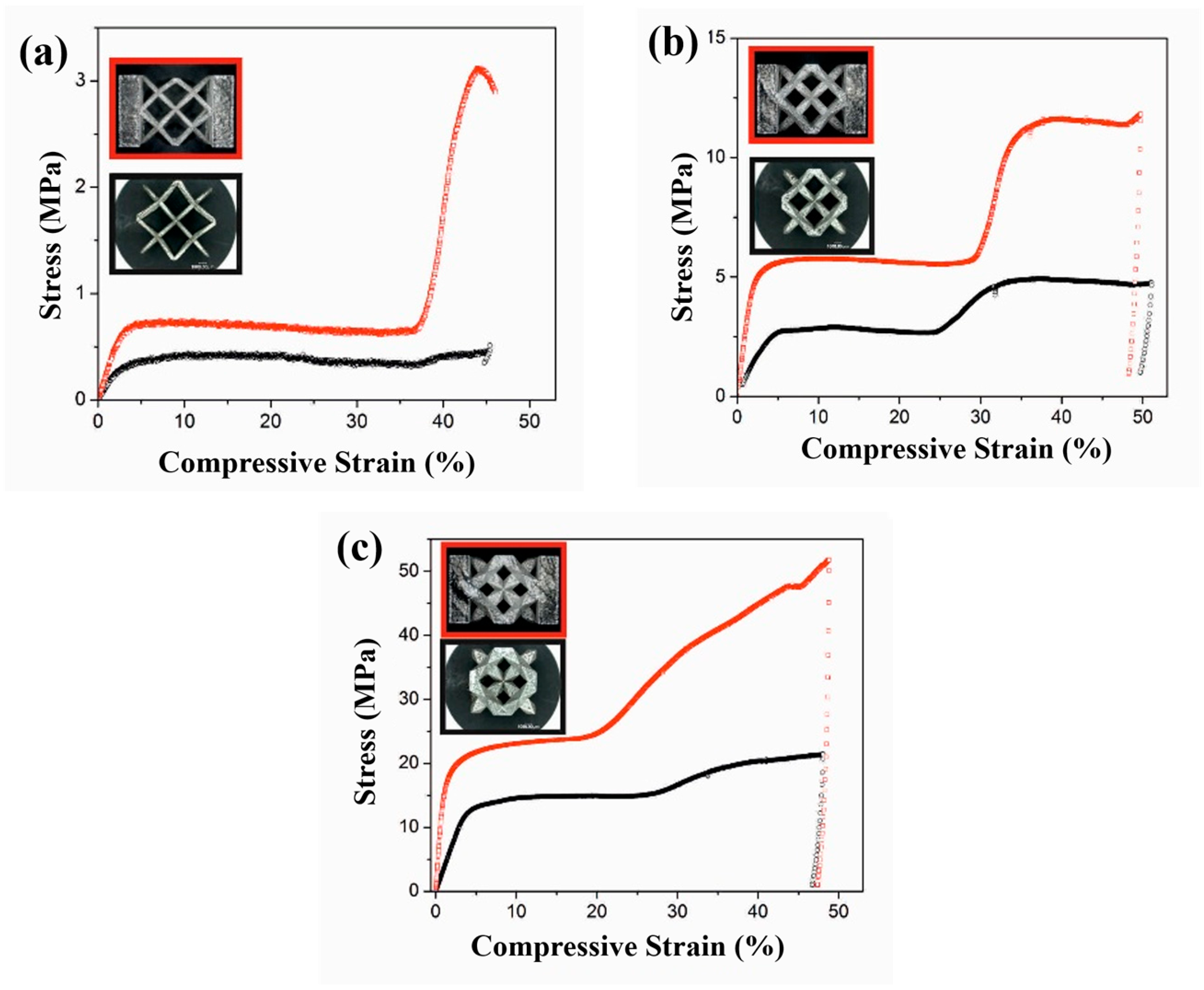
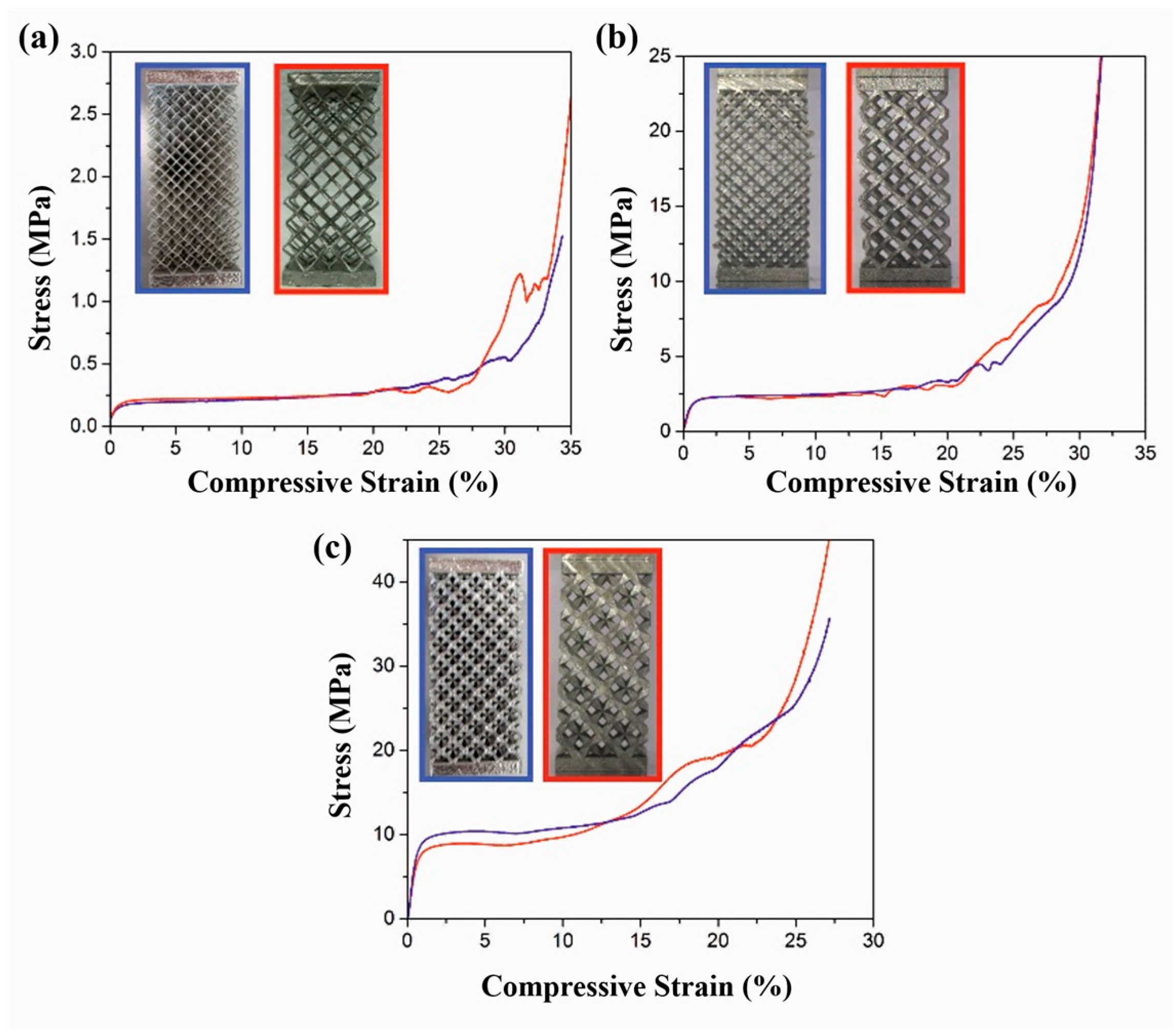
The digital scale was used to scale the parts in order to ascertain their relative densities. All of the samples were observed to have reached the desired density levels and the deviations were small enough (within the experimental errors) and, hence, were neglected. Although it has to be mentioned that the struts of the parts with a relative density of 4% are quite thin, and it was hard to remove the support structure without damaging the struts, a slight bending of the struts could not be fully prevented. The compression test results of the single-unit cells and the unit cells with base plates are shown in
Figure 8. The black curves in
Figure 8 correspond to the samples with single-unit cells and the red curves correspond to the samples with unit cells with base plates. At least three measurements were carried out in each condition and the samples show similar stress-strain behavior within the experimental limits. Hence, only one representative curve in each condition is shown here. It can be observed from these curves that the addition of base plates to the unit cells have a definite and drastic influence on the compression behavior of the unit cells with a significant increase in the stiffness, as well as the compressive strength of the cells. Apart from the similarity in the stiffness and the compressive strength between the samples with and without base plates, the samples with different relative densities also show similarities with a quasi-elastic regime in the beginning of the compression test, followed by a long plateau. The region with the long plateau experiences a marginal decrease in the compressive strength.
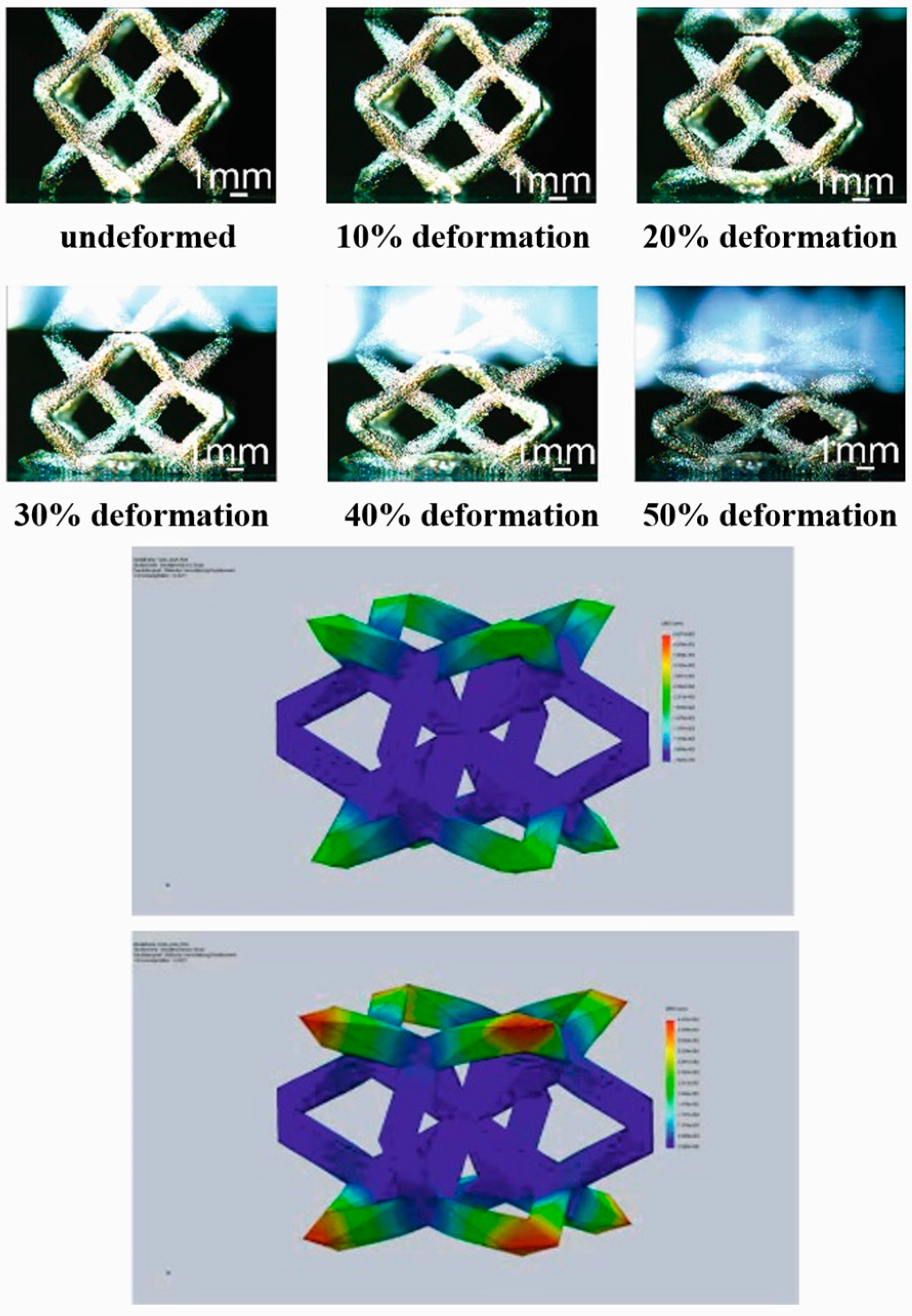
To better understand this effect, single-unit cells with a relative density of 12% were examined at different deformation levels and are shown in
Figure 9. After the quasi-elastic region, the deformation of the unit cell is highly localized in the upper and lower struts of the unit cell, whereas the central portions of the unit cells do not show significant deformation. It is reasonable to say that the inner struts of the unit cells have more joints than the upper and lower ones and are, thus, stable. In this particular case, and in the beginning of the compression test, the deformation is concentrated only in the lower struts, which might be correlated to the gravity effect, and this is observed in most of the unit cells tested under similar conditions. This might also possibly be due to the small defects found in the lower struts caused by the support structure or during its removal. Nevertheless, both the experiments and the predicted deformation behavior from the finite element method (FEM) are in good agreement. The FEM analysis predicts the highest deformation levels in the upper and lower regions, especially at the corner of the structure. Since the corners are sharp in nature it acts as the source for stress concentration and is maximum at these places. Similar results are observed from the experiments (
Figure 10), where the deformation is initiated at the lower struts (due to the presence of some minor defects, like the porosity and/or other imperfections that may be caused during the removal of the support structures after the SLM fabrication process). This is then followed by the deformation of the upper struts. However, the struts in the middle of the unit cell seem to be stable and do not deform because of the stability offered by the significantly higher number of joints in the middle of the unit cell.
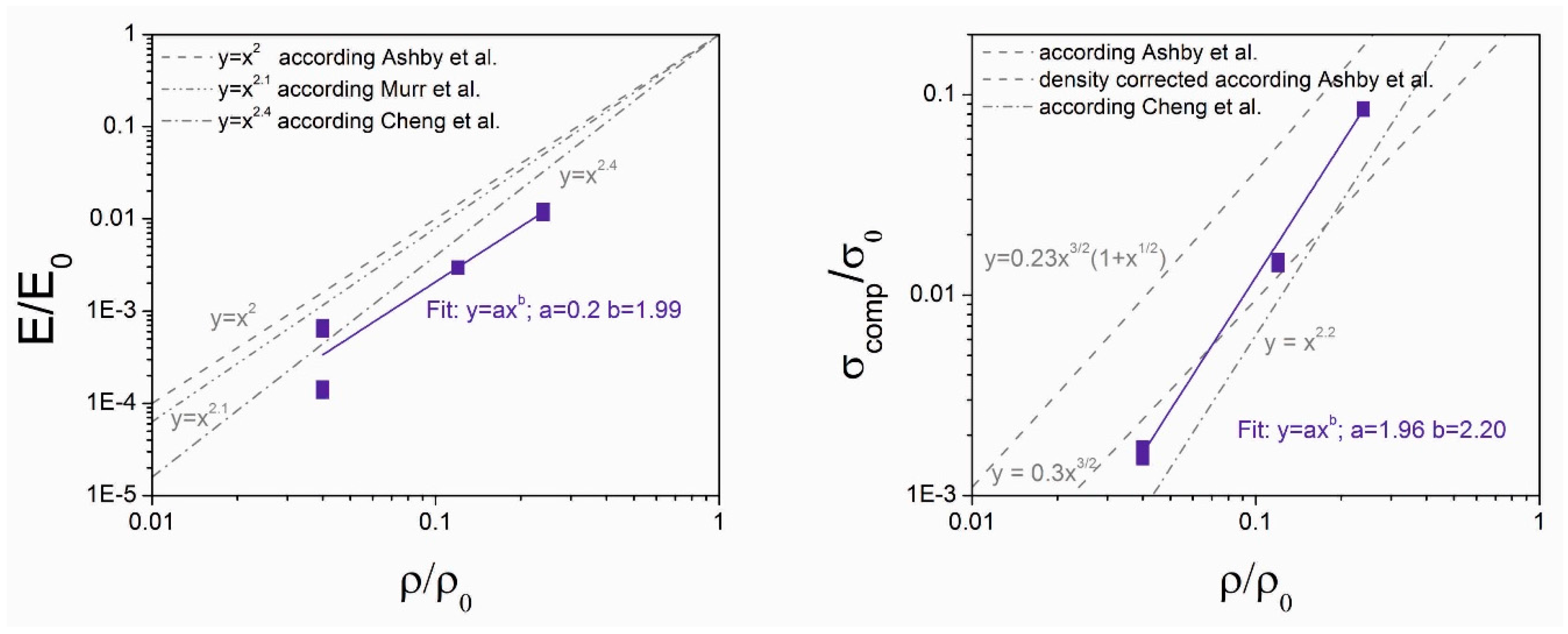
Over the past years, several theories have been established to evaluate the relation between cellular structures and their mechanical properties. The most popular and the most commonly used one is the Gibson-Ashby model proposed by Gibson and Ashby [
20]. They proposed that the relative modulus
, the relative strength
and the relative density
of open cellular structures follows the following equations:
where, the subscript 0 represents the properties of a fully-compact specimen.
The second equation for the relative strength includes a density correction, which takes into account that the dimensions of the cell corners must be subtracted from the length of the beam at higher densities. This second model was described by Ashby [
20]. Other authors have also produced similar lattice structures, like Murr et al. [
21], who used the technique of electron beam melting to melt comparable structures out of titanium and CoCr powder and tested them under compression [
21]. Cheng et al. [
22], on the other hand, has produced structures out of Ti-6Al-4V [
22]. The results from their experiments, as well as the results from this work, are displayed in
Figure 10. The results from Cheng et al. [
22] and Murr et al. [
21] slightly vary from those of Gibson and Ashby [
20], where Cheng et al. [
22] found a dependency for the elastic Young’s modulus:
while Murr et al. [
21] found a closer relationship with an exponent closer to the one of Gibson and Ashby:
Cheng et al. [
22] also found a relationship between the compressive plastic collapse strength and the relative density:
However, from
Figure 10, it can be observed that the results observed from the present work do show a similar trend, like the other works from Ashby et al. [
20], Murr et al. [
21], and Chang et al. [
22], within the experimental limits.
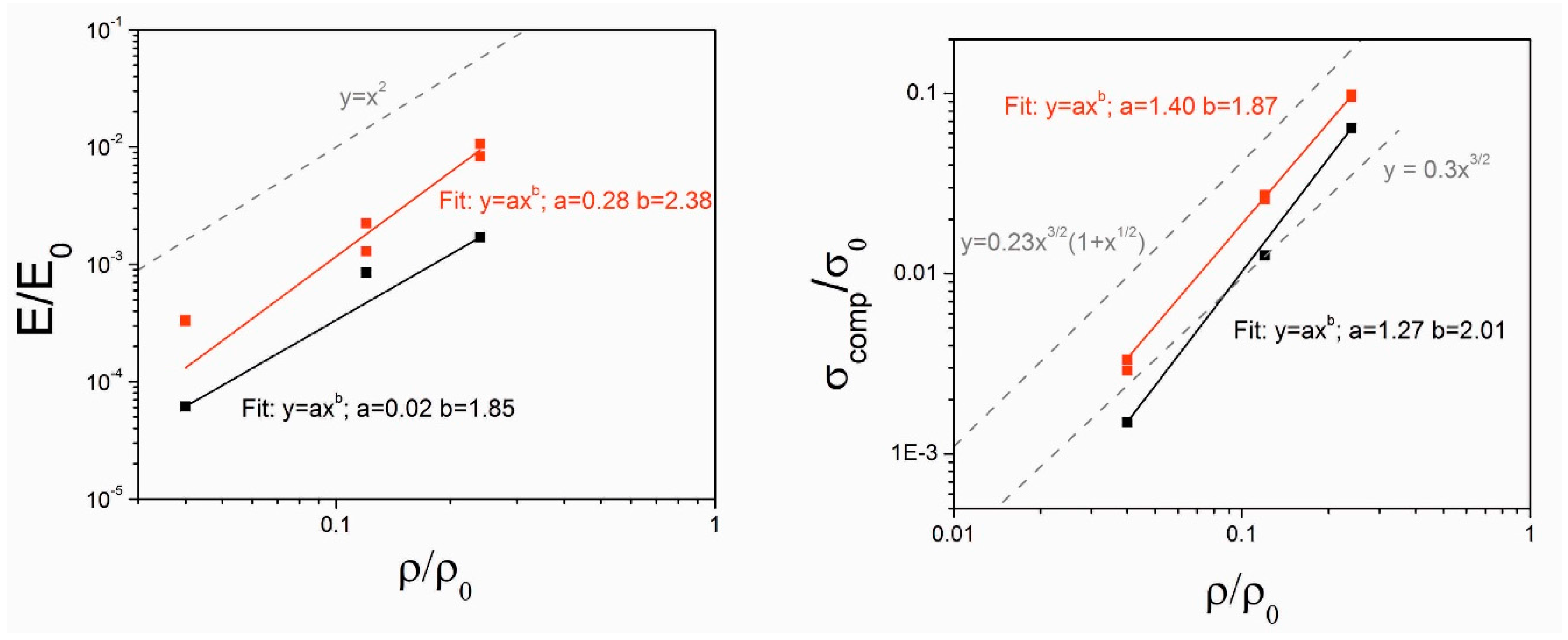
The results from the compression test is very similar to the FEM analysis performed and the result is summarized in
Figure 11. For the single-unit cells the following dependencies for the Young’s modulus and the compressive plastic collapse strength could be found:
and
For the single-unit cells with baseplates the results are slightly different:
and
In the present work, the compression test results vary between the different morphologies of the dodecahedron lattices. There is no obvious difference in the deformation, as well as in the mechanical key values, such as Young’s modulus or compressive plastic collapse strength, between the sandwich structures with a unit cell size of 1 cm
3 or the ones with the unit cell size of 125 mm
3 as displayed in
Figure 12 by the red and the blue curves. However, there are major differences observed between the single-unit cell and the unit cell with base plates, as well as with the sandwich structures. All of the equations were calculated with the following values of bulk elastic Young’s modulus: E
0 = 210 GPa and a bulk compressive plastic strength: σ
0 = 200 MPa, which correspond to the properties of conventional 316L steel. For the single-unit cells the results for the specific Young’s modulus and compressive plastic collapse are represented by Equations (7) and (8). The unit cells with base plates are not only stiffened but also the compressive plastic collapse strength is significantly enhanced, which can also be obviously observed from the fitted equations. For the unit cells with base plates, the specific Young’s Modulus and compressive plastic collapse were described in the Equations (9) and (10).
The equations from the Gibson-Ashby model [
20] was used to plot the curves and can be observed from
Figure 11. Both of the specimen geometries show a lower Young’s modulus than the values expected from the Gibson-Ashby model [
20]. Nevertheless, the curves from the experiments and the ones from the Gibson-Ashby model show similar slopes [
20]. For the compressive plastic collapse strength, the results from the experiments lie in between the two different models from Gibson and Ashby [
20]. The influence of the interactions between multiple unit cells in the two difference sandwich structures are investigated (2 × 2 × 4 and 4 × 4 × 8) and the results are summarized in
Figure 12. Again, only one representative curve in each structure is shown, because the other curves also show a similar trend within the experimental errors, explaining that the results are highly reproducible. The red curves correspond to the 2 × 2 × 4 structures and the blue curve to the 4 × 4 × 8. Interestingly the size of the unit cells and the number does not seem to play a major influence to the deformation behavior as well as the overall mechanical performance. The characteristic three different regions (observed during the compression of structures), the quasi-elastic region, the plateau, and the densification, can be well observed. For all three densities, the deformation behavior of the 2 × 2 × 4 and the 4 × 4 × 8 structures are very similar. Only at the beginning of the densification process can a small difference be observed between the 2 × 2 × 4 and the 4 × 4 × 8 structures. This could very well be due to the differences in the amount of semi-molten particles that are stuck on the surfaces of the struts, which could influence the densification behavior [
23]. The specimen geometries are quite similar to the ones produced by Murr et al. [
21], as well as from Cheng et al. [
22]; the results from their publication are displayed along with the present results (
Figure 10). Again, similar to the single unit cells with and without base plates, the Young’s modulus is lower than the theory (from Gibson and Ashby predicts). The present experimental results are also lower than the experimental results from Cheng et al. [
22] and Murr et al. [
21].
The most probable explanation for the reduction in properties can be attributed either to the presence of building defects along the struts, the residual porosity in the material, or the attached powder particles on the struts, which contribute to the density of the sample, but not its mechanical performance. The compressive plastic collapse strength of the samples, on the other hand, follows nearly perfectly the results from Cheng et al. [
22], where the present results show a slightly higher trend, but the inclination of the curves are very similar. Compared with the existing theories (Gibson and Ashby), the present experimental results lie in between the two different models with and without density correction. With the construction of three different density values of the structures, it was possible to deduce the parameters which describe the relations between the relative density and the mechanical performance, such as Young’s modulus or compressive strength. This may be used as a guideline to estimate the mechanical properties of the structures fabricated by SLM.


 ,
, 