Article

Intelligent Automated Monitoring and Curing System for Cracks in Concrete Elements Using Integrated Sensors and Embedded Controllers

by
Papa Pio Ascona García
1,*,
Guido Elar Ordoñez Carpio
2,
Wilmer Moisés Zelada Zamora
2,
Marco Antonio Aguirre Camacho
1,
Wilmer Rojas Pintado
1,
Emerson Julio Cuadros Rojas
3,
Hipatia Merlita Mundaca Ramos
4 and
Nilthon Arce Fernández
5
1
Academic Department of Engineering, Faculty of Engineering, National Intercultural University Fabiola Salazar Leguía de Bagua, Bagua 01721, Peru
2
Academic Department of Engineering, Faculty of Civil Engineering and Architecture, Universidad Nacional Toribio Rodríguez de Mendoza de Amazonas, Chachapoyas 01001, Peru
3
Department of Civil and Environmental Engineering, Faculty of Roads, Canals and Ports, Universitat Politècnica de Catalunya Barcelona Tech—UPC, 08034 Barcelona, Spain
4
Academic Department of Biotechnology, Faculty of Natural and Applied Sciences, National Intercultural University Fabiola Salazar Leguía de Bagua, Bagua 01721, Peru
5
Academic Department of Basic and Applied Sciences, School of Engineering, Universidad Nacional de Jaén, Jaén 06800, Peru
*
Author to whom correspondence should be addressed.
Technologies 2025, 13(7), 284; https://doi.org/10.3390/technologies13070284
Submission received: 22 May 2025 / Revised: 19 June 2025 / Accepted: 25 June 2025 / Published: 3 July 2025
(This article belongs to the Section Construction Technologies)

Abstract

This study addresses the formation, detection, and repair of cracks in concrete elements exposed to temperatures above 25 °C, where accelerated evaporation compromises their structural strength. An automated intelligent curing system with embedded sensors (DS18B20, HD-38) and Arduino controllers was developed and applied to solid slabs, columns, and concrete test specimens (1:2:3.5 mix ratio). The electronic design was simulated in Proteus and validated experimentally under tropical conditions. Data with normal distribution (p > 0.05) showed a significant correlation between internal and ambient temperature (r = 0.587; p = 0.001) and a low correlation in humidity (r = 0.143; p = 0.468), indicating hygrometric independence. The system healed cracks of 0.01 mm observed two hours after pouring the mixture, associated with an evaporation rate of 1.097 mL/s in 4 m2. For 28 days, automated irrigation cycles were applied every 30 to 60 min, with a total of 1680 L, achieving a 20% reduction in water consumption compared to traditional methods. The system maintained stable thermal conditions in the concrete despite ambient temperatures of up to 33.85 °C. A critical evaporation range was identified between 11:00 and 16:00 (UTC-5). The results demonstrate the effectiveness of the embedded system in optimizing curing, water efficiency, and concrete durability.

1. Introduction

In the Peruvian Amazon, concrete structures face extreme temperature and humidity conditions, which accelerate the evaporation of mixing water and affect the cement hydration process. This situation compromises the strength and durability of the material, increasing the risk of microcracks and structural failures, especially in self-built buildings with poor materials and inadequate curing techniques [1].
Traditional curing methods, such as water spraying, the use of sealing membranes, and steam curing, have limitations in remote regions and extreme tropical climates due to uncontrollable environmental factors and the lack of continuous technical supervision [2,3].
Automation and the Internet of Things (IoT) offer more efficient alternatives through intelligent systems capable of monitoring variables such as surface moisture, internal concrete temperature, and incipient crack formation in real time [4].
This research proposes the design and validation of an intelligent curing monitoring system that integrates sensors, embedded controllers, and actuators to detect, characterize, and rehabilitate cracks in structural elements. Unlike previous approaches, emphasis is placed on the system’s adaptability to real field conditions, ensuring optimal concrete hydration through embedded control algorithms [5,6,7].
This technological approach represents an innovative solution for improving the quality and durability of constructions in adverse climatic environments.

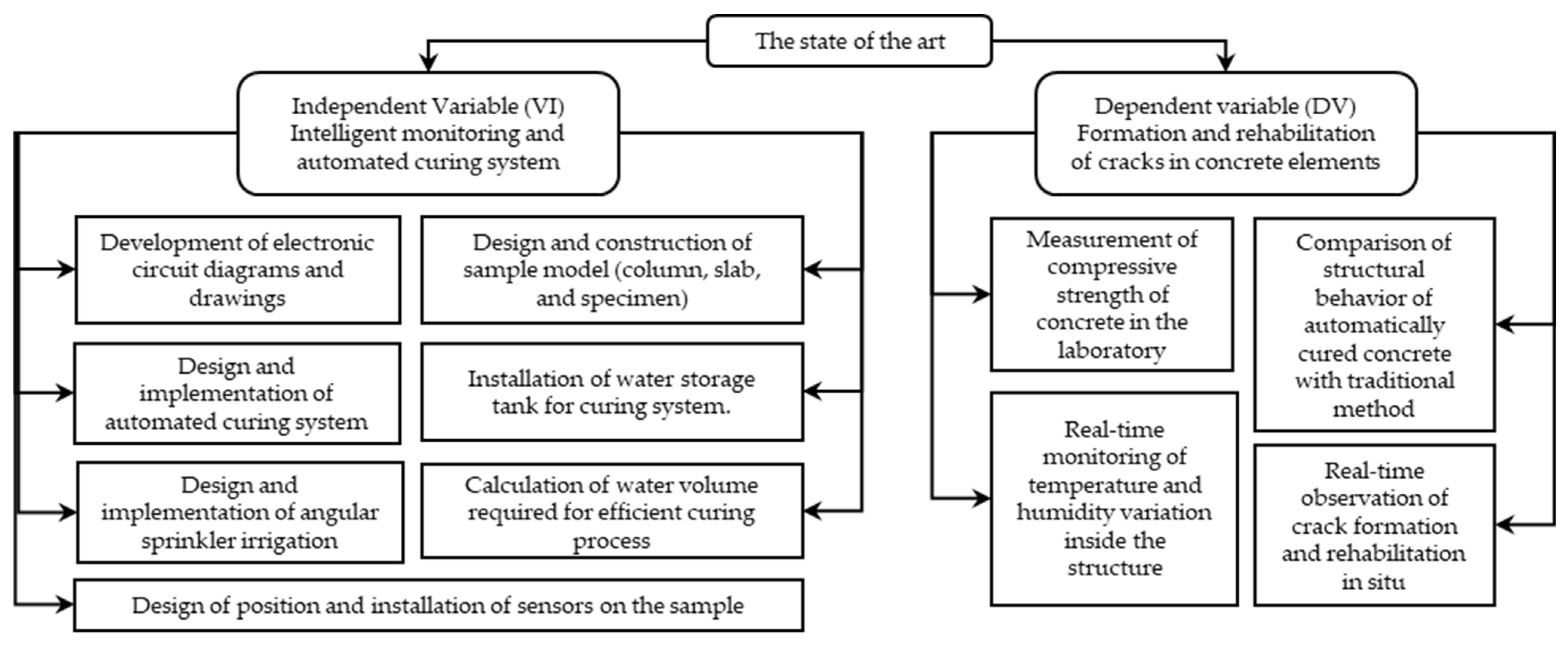
1.1. State of the Art

The structural integrity of concrete in high-temperature and high-humidity environments has been the subject of various studies, demonstrating its impact on the durability and mechanical strength of the material. It has been shown that high temperatures affect porosity and reduce compressive strength, while higher relative humidity improves mechanical properties [8].
Traditional curing methods include wet curing, sealing membranes, and the use of steam, influencing the permeability and strength of concrete [9,10]. However, their effectiveness is limited in tropical regions, where environmental factors and a lack of supervision affect the process.
Emerging technologies have addressed these challenges through smart sensors, enabling the real-time monitoring of humidity, temperature, and deformation. Recent research has developed embedded optical and wireless sensors to improve quality control during setting [11,12].
In curing automation, water management systems have been proposed that regulate irrigation with real-time data, optimizing early strength and reducing crack formation [13]. Automatic monitoring systems have also been implemented, minimizing water waste and improving remote strength monitoring [14] and technical standards [15,16,17].
These advances highlight the need for intelligent, adaptive, and autonomous solutions, especially in the Peruvian Amazon, where extreme conditions compromise the effectiveness of traditional curing and demand technological innovations to ensure the durability of concrete. Details can be seen in Figure 1.

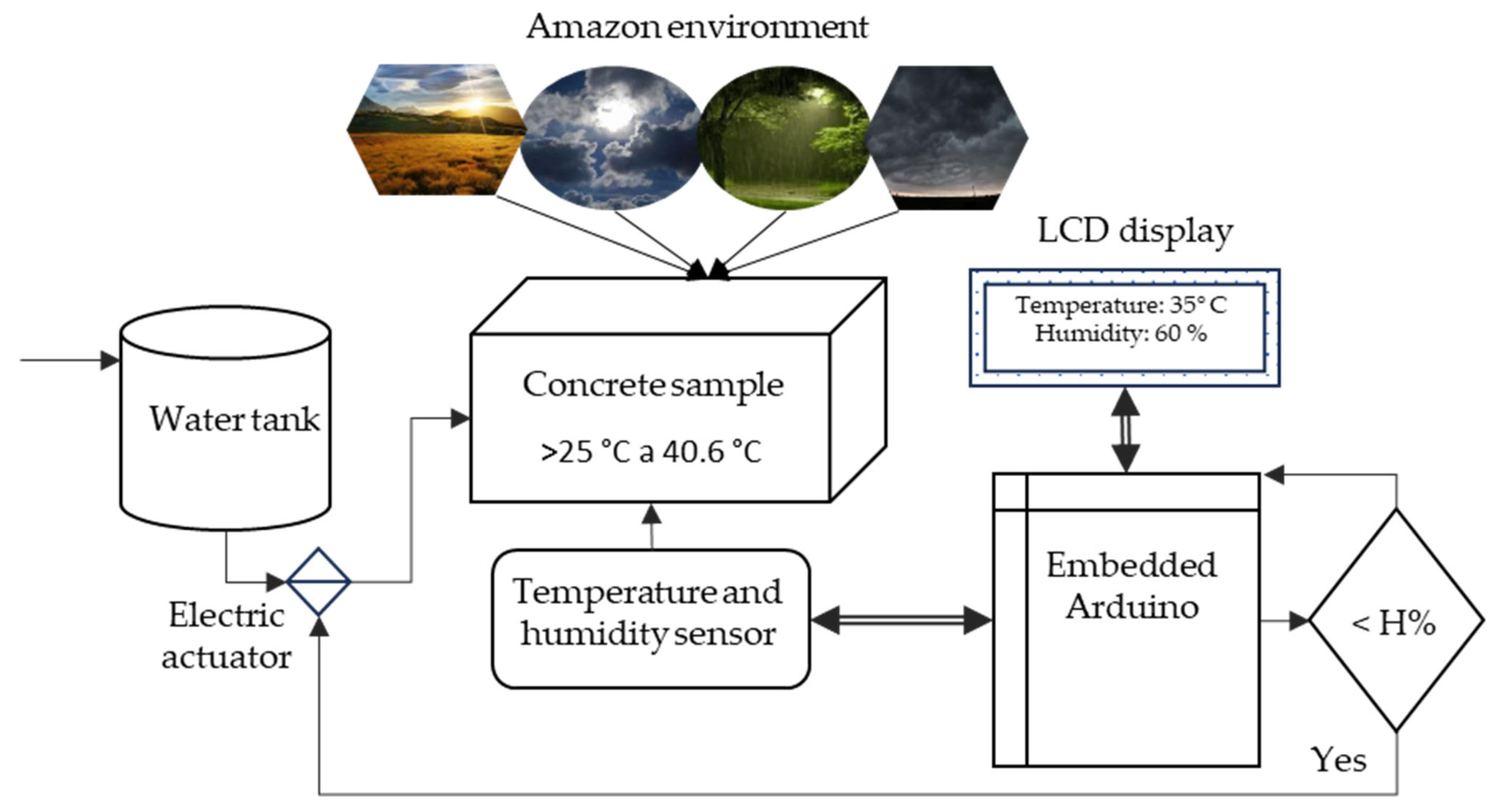
1.2. Intelligent Monitoring and Automated Curing System

Real-time monitoring of concrete curing using sensors, Arduino, and actuators represents an efficient technological solution compared to traditional methods, which are generally costly, inaccurate, or difficult to automate. This approach allows for the control of key variables such as compressive strength (f’c), internal temperature, and relative humidity in structural elements, improving crack control, optimizing resources, and reducing economic risks in civil works in the region.
Temperature and relative humidity sensors are installed in the concrete to monitor strength and moisture loss, following the guidelines of ASTM F2170 to ensure accurate measurement [20]. This principle is the basis of modern monitoring systems, where embedded sensors collect and transmit data through IoT platforms, allowing for continuous analysis. In addition, recent studies optimize curing conditions by partially replacing cement with nanoparticles and applying controlled heat, achieving substantial improvements in the mechanical strength of concrete [21].
The curing process in slabs and columns must ensure adequate hydration of the cement, preventing cracking and allowing for the optimal development of mechanical properties. Continuous monitoring systems allow for the identification of anomalies, detection of bottlenecks, and collection of data for predictive analysis [22,23]. Among the most monitored properties is electrical conductivity, which correlates directly with ultrasonic pulse velocity, penetration resistance, and material maturity [24]. Ultrasonic sensors, integrated with GSM and GPS modules, are capable of detecting invisible cracks and sending real-time alerts, which improves structural safety [25]. The highly sensitive and non-destructive acoustic emission (AE) technique allows the detection of microcracks in their early stages, which is useful for adjusting curing parameters before significant damage occurs [26]. These technologies are compatible with IoT systems that facilitate continuous structural assessment, optimizing water use, formwork removal time, and concrete performance [27].
Early monitoring of concrete compressive strength is crucial, especially in harsh climates. In this context, non-destructive techniques based on IoT have been developed that accurately estimate this key property to safely advance the construction process [28]. In addition, the automation of drip and sprinkler irrigation using IoT has been explored with good results in curing efficiency [29].
The use of guided ultrasonic waves (GUWs) has made it possible to assess the degree of corrosion in reinforced elements, observing how thickness influences wave propagation and the appearance of cracks [30]. Likewise, through digital image correlation (DIC) and piezoelectric sensors (PZTs), it has been possible to quantify deformations and crack growth with great precision [31].
Recent research has also applied imaging sensors and flow meters to monitor the amount and distribution of the curing agent, transmitting the data to cloud platforms [32]. In addition, computed tomography technologies have been used to analyze the microstructure of concrete and classify cracks according to their morphology [33].
Electromechanical impedance (EMI) and electromagnetic wave propagation techniques, based on piezoelectric materials, together with humidity and temperature sensors, enable highly sensitive and continuous monitoring of the concrete curing process. This technological integration is essential for controlling environmental conditions in smart structures and advancing the development of concrete with adaptive response capabilities [34,35].
Other studies have used image recognition to identify concrete surface textures, classifying the level of curing achieved [36]. Although there have been significant advances, it is recognized that the full potential of the Internet of Things (IoT) to improve curing has not yet been fully explored [37].
In their study, ref. [38] evaluated automated IoT curing systems, comparing them with traditional methods and demonstrating their efficiency in controlling surface moisture using precision sensors. At the molecular level, computational simulations allow us to understand the chemical reactions during cement hydration, paving the way for more sustainable formulations [39].
Finally, the incorporation of Arduino as the central control platform optimizes the efficiency of the system by facilitating the acquisition, processing, and automated response to sensor data. Functions such as motor activation, fan control, and LCD are possible. In addition, connecting via Ethernet or Wi-Fi modules (Node MCU) facilitates communication with web servers and secure storage [40,41]. Figure 2 shows the configuration applied to the concrete monitoring system.

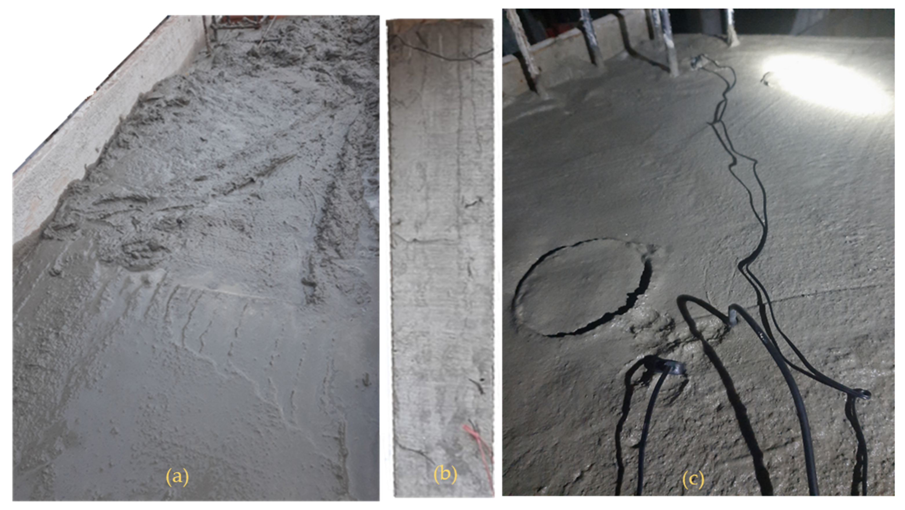
1.3. Formation and Rehabilitation of Cracks in Concrete Elements
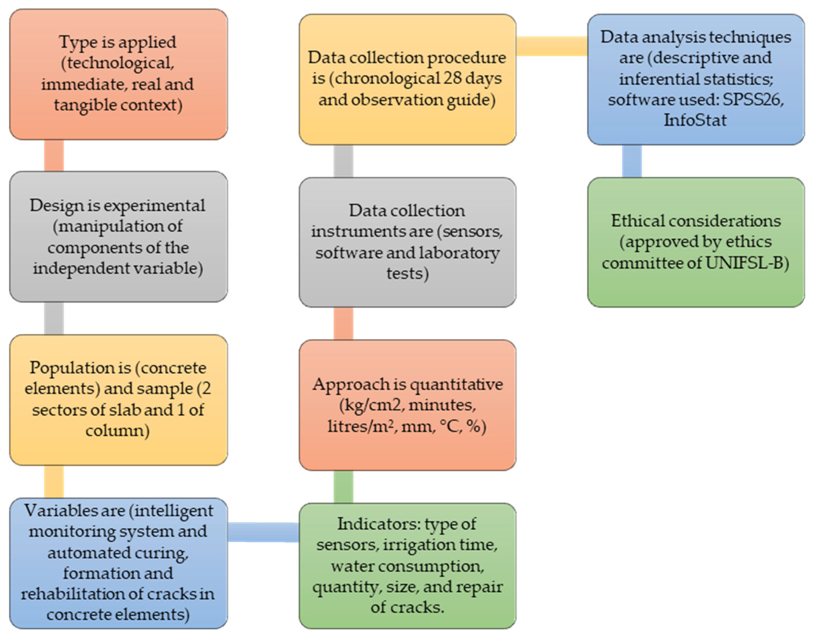
Proper curing of concrete is essential to prevent cracking during its initial hardening. Poor curing causes excessive evaporation, reducing cement hydration and affecting strength, durability, and impermeability [42]. Figure 3 shows traditional curing methods.
This process must control temperature and humidity, since if the internal relative humidity falls below 80%, hydration ceases [43].
Figure 3. Concrete curing methods: time, temperature, and humidity (adapted from [44,45]).
Technologies 13 00284 g003
Steam curing, despite accelerating early strength development by up to 193% [46], can lead to porosity, low durability, and uneven hydration distribution [47]. The standard water method involves high water consumption [48], although it guarantees better resistance to chloride ions [49]. Extreme temperatures modify the microstructure of concrete and the glass transition of epoxy [50,51].
The use of additives, recycled fibers (RTSFC40), and techniques such as immersion curing or wet blankets can significantly reduce surface cracks [52]. The moisture content of aggregates also affects early strength [53,54]. In addition, prolonged spraying improves curing uniformity [55].
Recent studies analyze the compressive strength of concrete using probabilistic models that consider the effect of size [56] and machine learning techniques to predict it both in the hardened state [57] and at very early ages [58].
By knowing the compressive strength of concrete, it is possible to optimize the dosages and adjust its properties according to the specific requirements of the construction site, thus improving its performance and durability.
Cracks, influenced by drying shrinkage or adverse weather conditions, affect structural integrity. Their diagnosis is complex and dependent on human judgment [59,60], although they can be mitigated with additives, reducing their width by up to 66%.
The development of hybrid technologies and computer simulations facilitates the rehabilitation and structural prevention of cracks in concrete [61].
The equations used in the study, such as [62], calculate the evaporation rate using the following formula:
E = 5 ( [ T c + 18 ] 2.5 r ( [ T a + 18 ] 2.5 ) ( V + 4 ) 10 ( 2 )
where E is the evaporation rate (kg/m2/h). Tc is the concrete temperature (°C). Ta is the relative temperature (°C). r is the relative humidity (%). V is the wind speed (km/h).
V = ρ g h 1 + h 2
P = ρ g h 1 + h 2
where P = pressure in pascals (Pa), ρ = density of water (1000 kg/m3), g = gravitational acceleration (9.81 m/s2), h1 = height of water in tank (1.65 m), h2 = additional height of tank above ground 1.00 m, and V = outflow velocity of liquid in the Torricelli equation [63,64].
V = h r A V = π r 2 h
Q = V t
where V or Vt = tank volume (m3), r = required water height (m), A = area to be irrigated (m2), t = irrigation time (s), tank height (ht), g = gravity (9.81 m/s2), and Q is the required flow rate (L/s) [65]; likewise, h is the height in meters, ρ is the density of water equivalent to (1000 kg/m3), and g is gravity (9.8 m/s2).
For the calculation of the compressive strength of concrete, the following formula was used:
f c = P A
where P represents the maximum axial load applied (kg) and A the cross-sectional area of the cylinder (cm2). The data acquisition and recording were trouble-free, partly due to the adequate location of the physical model and the effectiveness of the integrated monitoring system [66].
In order to linearize non-linear relationships and facilitate their statistical or graphical analysis, we used
l n ( y ) = l n ( k ) + n l n ( x )
where y is the dependent variable. x is the independent variable. k is the multiplicative constant (log intercept). n is the exponent (log slope). Likewise, the equation of Clausius–Clapeyron’s law [67] is as follows:
P ( T ) = P 0 ( T 0 ) exp Δ Q k ( 1 T 1 T 0 ) L n P 2 P 1 = Δ H R ( 1 T 2 1 T 1 )

2. Methods

This study was developed as an applied, experimental, and quantitative investigation [68], aimed at designing and validating an intelligent system for automated monitoring and repair of cracks in concrete. The methodology was structured in sequential phases ranging from experimental design to statistical analysis.
In the experimental design, the independent variable was intentionally manipulated [69], following the guidelines of [70], to evaluate the impact of the intelligent system on crack formation and rehabilitation. Sampling was parametric by clusters [71], using slabs, columns, and test tubes as experimental units representative of real conditions [72].
The technical implementation included temperature (DS18B20) and humidity (HD-38) sensors, actuators (sprinklers and solenoid valves), and Arduino microcontrollers. A functional prototype was built that allowed preliminary software and hardware testing, with adjustments according to [73].
Laboratory and field tests were carried out. Compressive strength (f’c) was measured with a PINZUAR press (Lima, Peru), and environmental conditions and induced cracks were monitored. Statistical analysis included descriptive and inferential statistics: normality tests (Shapiro–Wilk), ANOVA, and Pearson correlation, with the support of SPSS26, InfoStat (version 2020), and Tableau (version 2024.3) [74].

2.1. Variables and Indicators

The operational variables allowed the effect of the system on curing and rehabilitation to be evaluated.
(a) Automated curing system: Evaluated using indicators such as monitoring frequency (between 30 and 60 min), response time (<5 s), curing duration (28 days), water consumption (L/m2), logic, and control code.
(b) Crack formation and rehabilitation: Resistance (MPa), crack formation time (min), crack length and width (cm and mm), percentage reduction in cracks, and rehabilitation (L/m2) were measured.

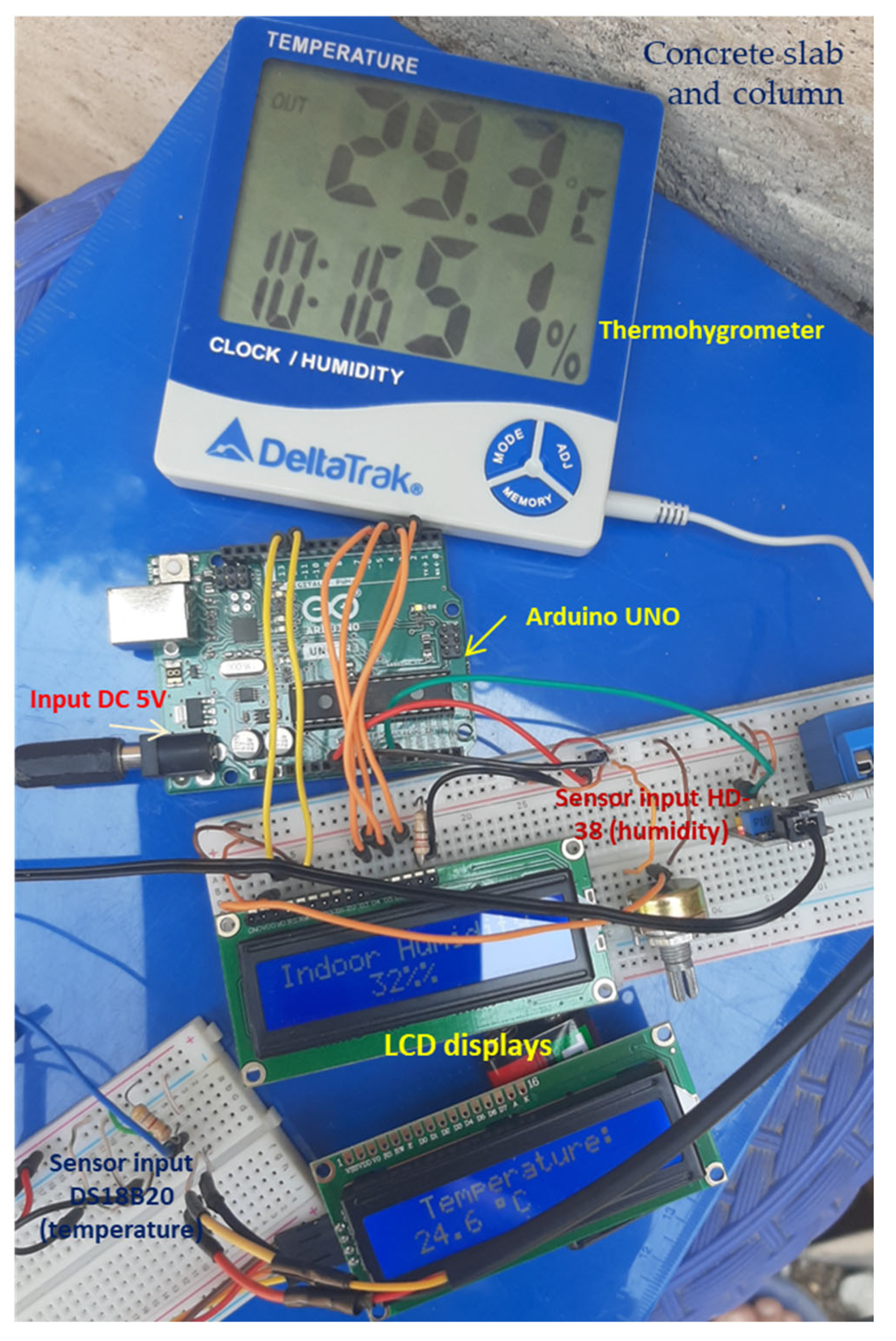
2.2. Instruments and Materials

Electronic equipment, specialized sensors, and construction materials appropriate to the objectives of the study were used.
(a) Instruments: Thermohygrometers (DeltaTrak Inc., Pleasanton, CA, USA), DS18B20 (Analog Devices, Wilmington, MA, USA) and HD-38 sensors (Generic manufacturing, Temecula, CA, USA), Arduino UNO boards (Arduino.cc, Monza, Italy), power supplies (MEAN WELL, New Taipei City, Taiwan), RLC devices (MICROTEST, New Taipei City, Taiwan), and LCD screens (Lumex, Carol Stream, IL, USA) for real-time control.
(b) Software: AutoCAD 2025 (version 2024) for mold design; Proteus (version 8.14 SP3, year 2023), Multisim (version 14.3.0), and QElectroTech (version 0.90) for circuit simulation; and Arduino IDE (version 2.3.0) for embedded programming.
(c) Materials: Cement, gravel, and water in wooden molds designed for columns, slabs, and test tubes, replicating real-world conditions. The instruments were calibrated in advance, and the measurements were validated with recognized standards.

2.3. Procedure

The methodological process included six ordered stages:
  • Sample preparation: Design and manufacture of standardized molds; mixing and pouring of concrete with homogeneity.
The experiment was carried out on a site located at UTM coordinates 17 M 0772723/9376835, at an altitude of 432 m above sea level, selected for its environmental influence on the concrete curing process. Factors such as altitude, temperature, relative humidity, and atmospheric pressure were considered due to their effect on the properties of concrete and the accurate functioning of the sensors in real field conditions.
Figure 4 shows the non-critical structural model for the experiment, consisting of a frame with an upper slab and vertical columns, in which the locations of the embedded sensors are specified. Temperature (T°C) and relative humidity (H%) sensors were installed in two positions on the slab: P1 (T°CP1/H%P1) and P2 (T°CP2/H%P2), as well as in a vertical column (T°CC1/H%C1). A digital thermohygrometer (T–H) complemented the system, recording external environmental conditions in real time.
2.
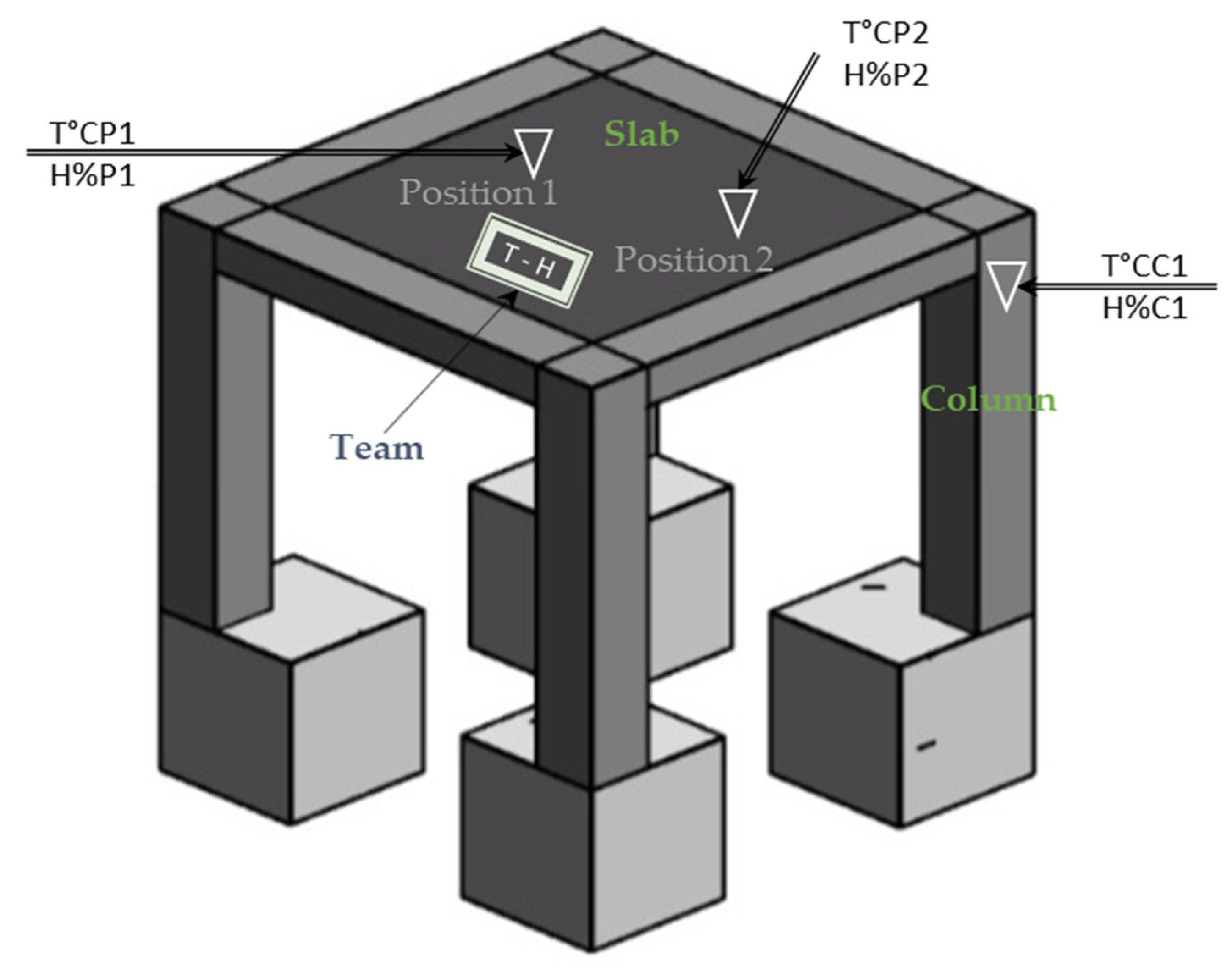
Sensor installation: Strategic placement of sensors to capture surface and internal thermal and humidity variables.
This configuration allowed for the collection of comparative data both on the surface and inside the concrete during the curing process. Figure 5 shows the initial stage of the experimental process; Figure 6 shows the sensor installation; Figure 7 shows the electronic circuit design; Figure 8 shows the real-time concrete curing circuit; and Figure 9 shows the diagram of the elevated tank together with the control circuit. It was found that the location, depth, and distribution of the sensors affect the accuracy of the measurements, reaffirming the importance of rigorous technical criteria in their positioning.
3.
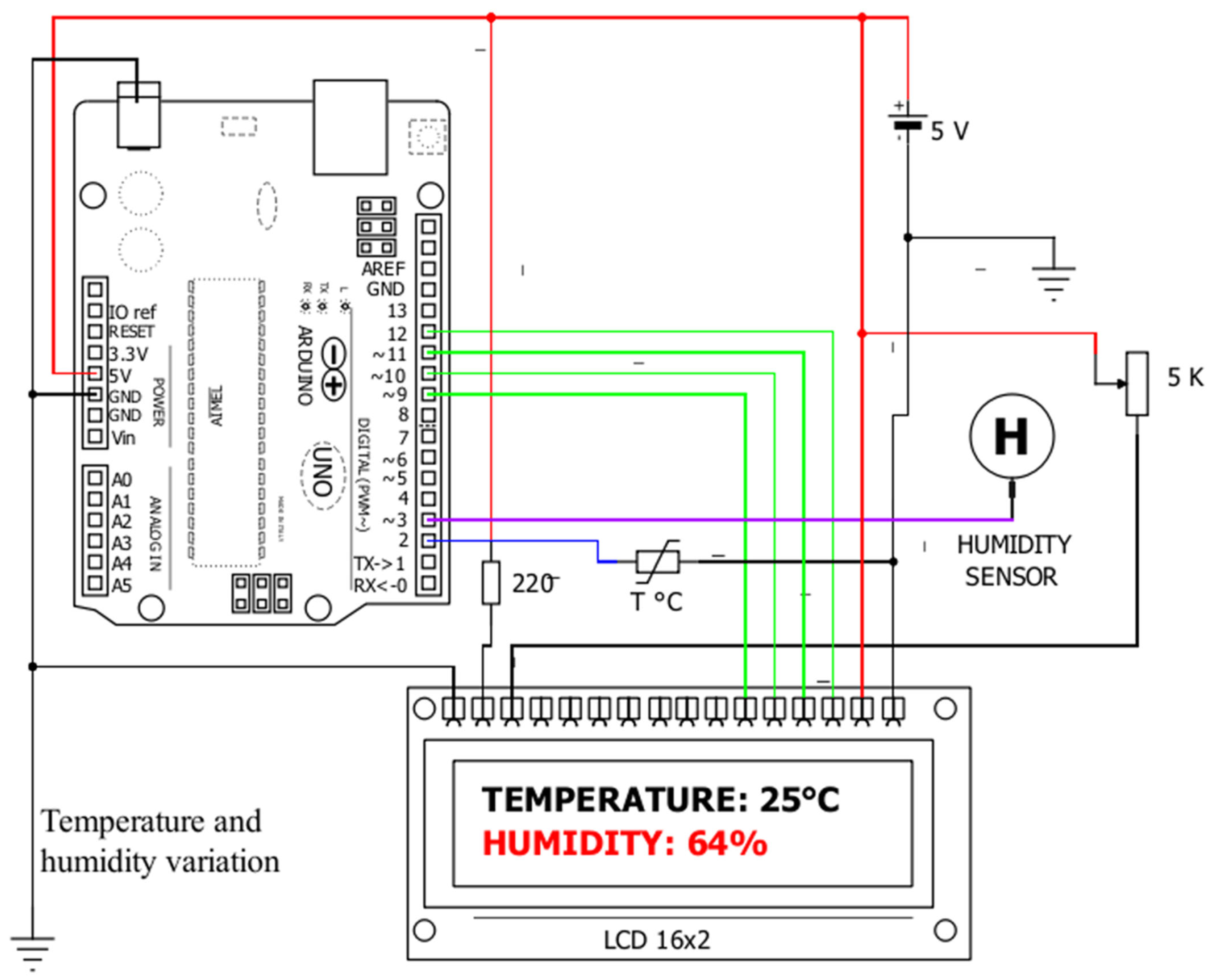
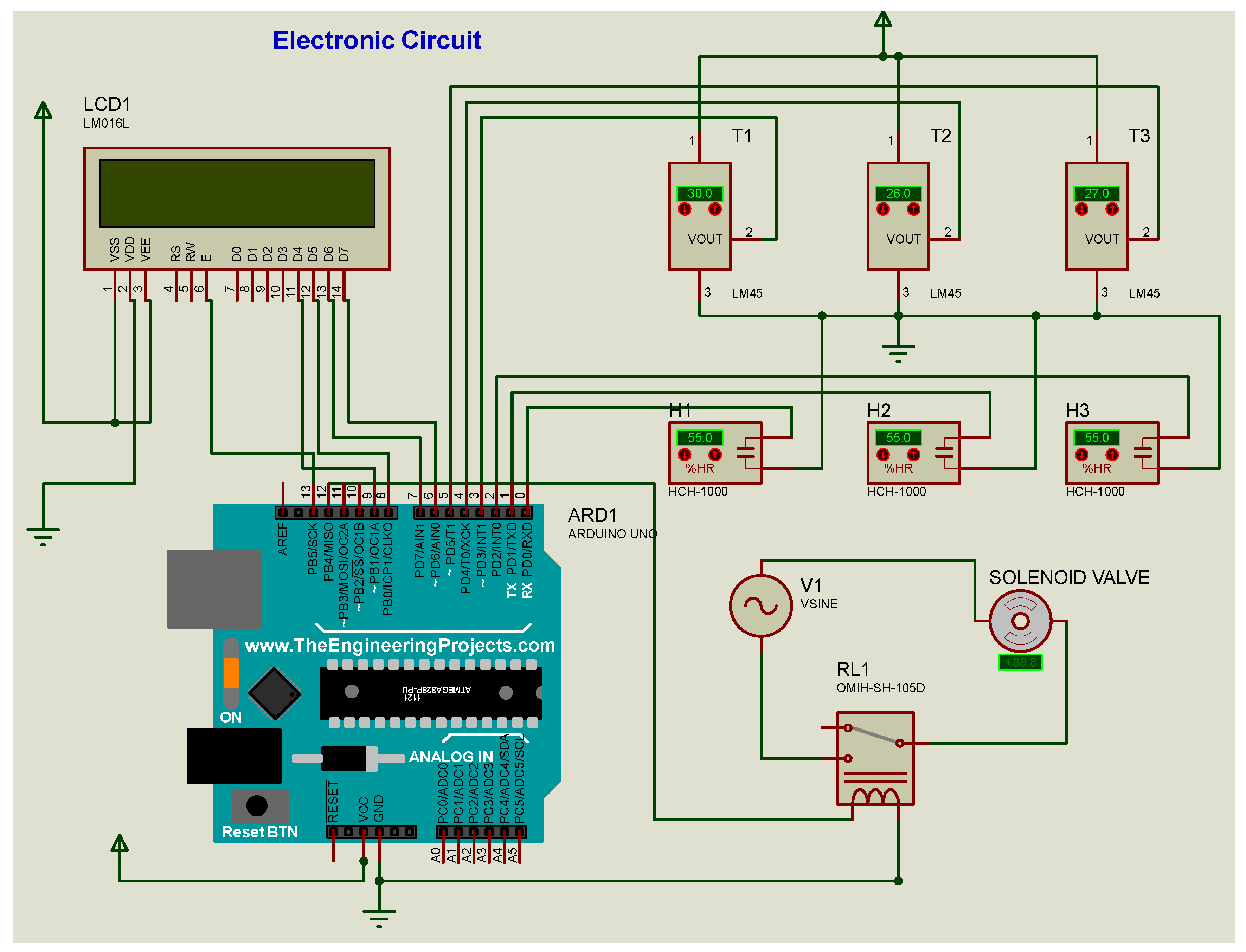
Design and Monitoring: Use of Arduino for automated data recording (internal environmental conditions), which is displayed on LCD screens.
4.
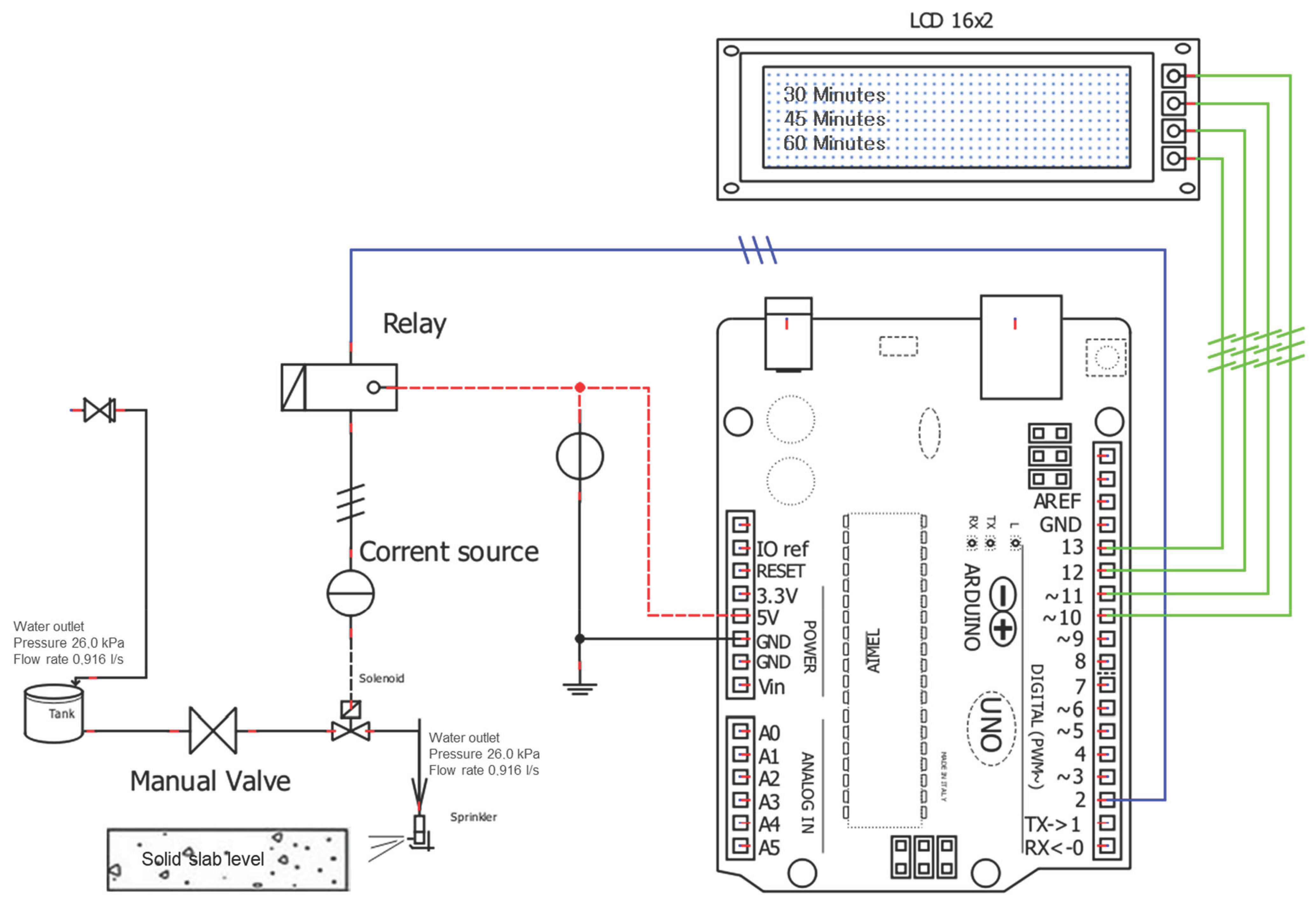
Curing activation: Embedded algorithm analyzed data and activated sprinklers and solenoid valves when deviations from defined thresholds (min) occurred, ensuring optimal conditions during curing.
5.
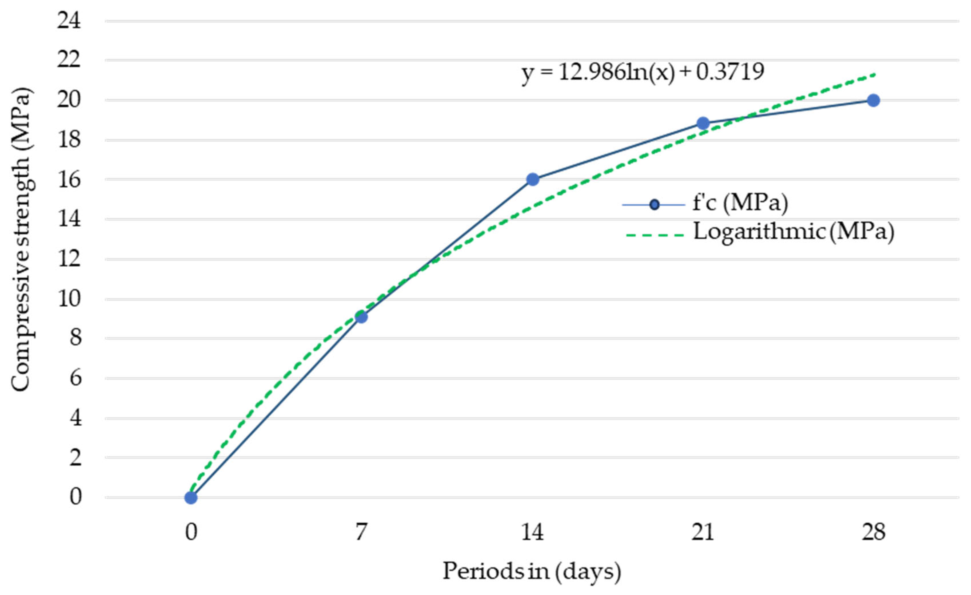
Strength measurement: At 7, 14, and 21 days, compressive strength tests were performed in accordance with national and international technical standards: the National Building Code (RNE), ASTM C39, and ISO 1920-10. [75].
6.
Analysis: Statistical processing with SPSS, InfoStat, and Tableau, comparing data with ISO 5725 standards and scientific literature [76,77].

2.4. Methodological Quality

The research followed R & D & I standards, in accordance with [78,79]. Traceability, transparency, and reproducibility were guaranteed. The methodological design rigorously controlled the variables, ensuring high internal and external validity. All the experimental stages applied calibration and validation criteria to maximize reliability.
Finally, Figure 10 visually summarizes the methodology applied, from experimental design to validation, highlighting technological integration, the evidence-based approach, and its applicability in real contexts.

3. Results

3.1. Evaluation of Mechanical Behavior Through Compression Tests

The structural and mechanical properties of concrete elements—columns, slabs, and cylindrical test specimens—manufactured under controlled conditions were evaluated. The structural slab, modeled in AutoCAD, measured 2.0 × 2.0 m with a thickness of 0.2 m, accompanied by columns measuring 0.25 × 0.25 m and 1.5 m high, and footings 0.6 m deep. A volumetric mix ratio of 1:2:3.5 (cement/sand/gravel) was used.
The cylindrical specimens (30 cm high, 10.15 cm in diameter, area of 0.0081 m2, and average weight of 5.15 kg) were subjected to axial compression tests with a calibrated hydraulic press. Breaking loads of 74 kN (7 days), 130 kN (14 days), and 153 kN (21 days) were recorded. Applying the standard formula, resistances of 9.13 MPa, 16.03 MPa, and 18.87 MPa were obtained, with a logarithmic trend of 20 MPa at 28 days, showing a progressive increase in line with the expected mechanical development of the concrete. These results comply with RNE E.060, NTP 334.090, and ASTM C39 standards and reflect the positive influence of automated curing managed by embedded sensors and electronic controllers under controlled conditions.
Figure 11 shows a real trend in the increase in strength, confirming the effectiveness of the automated monitoring system in tracking the curing process, a key element for early structural rehabilitation and crack prevention. The proposed mathematical model (Equation (7)) showed high predictive capacity.
Overall, the results validate that the application of embedded technology—sensors and microcontrollers—during the curing process contributes to a significant increase in mechanical strength, which reduces the probability of crack formation and improves the structural performance of concrete.

3.2. Verification of the Efficiency and Performance of the Electronic System

The electronic system developed demonstrated high functional efficiency in the automation of concrete curing. Sensors, actuators, and Arduino UNO boards were integrated into a hybrid analog–digital architecture, enabling the real-time monitoring of temperature and humidity and optimizing automatic control of irrigation through sprinklers controlled by solenoid valves (Figure 7 and Figure 8).
Simulations performed in Proteus and Multisim validated the behavior of the circuit before its physical implementation, reducing errors and costs. The temperature (T1, T2, and T3) and humidity (H1, H2, and H3) sensors were strategically distributed, generating reliable three-dimensional data from inside the concrete.
This embedded technology enabled precise curing management, which directly contributed to reducing early crack formation.
The DS18B20 (temperature) and HD-38 (humidity) sensors showed high sensitivity and stability, even in the face of thermal variations. The direct digital output eliminated the need for ADC, simplifying the circuit and improving sampling accuracy. The Arduino IDE serial monitor validated stable operation in the face of external disturbances.
The programmed code established control thresholds that automatically activated solenoid valves, ensuring optimal curing conditions 24 h a day (see Table 1).
This embedded system not only facilitated automated management but also contributed to the early detection of unfavorable conditions that can cause microcracking, allowing for timely rehabilitation.
In addition, its predictive capacity in the face of extreme environmental conditions increases the efficiency of the curing process and strengthens structural durability, validating its applicability in civil works exposed to critical climates.

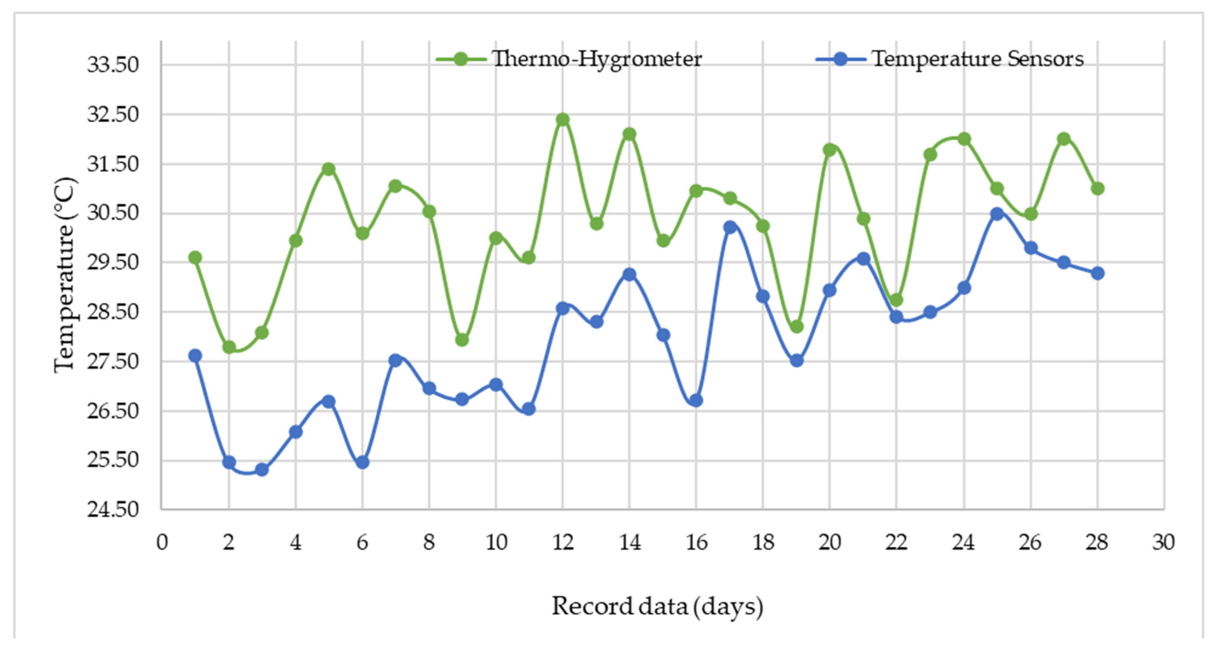
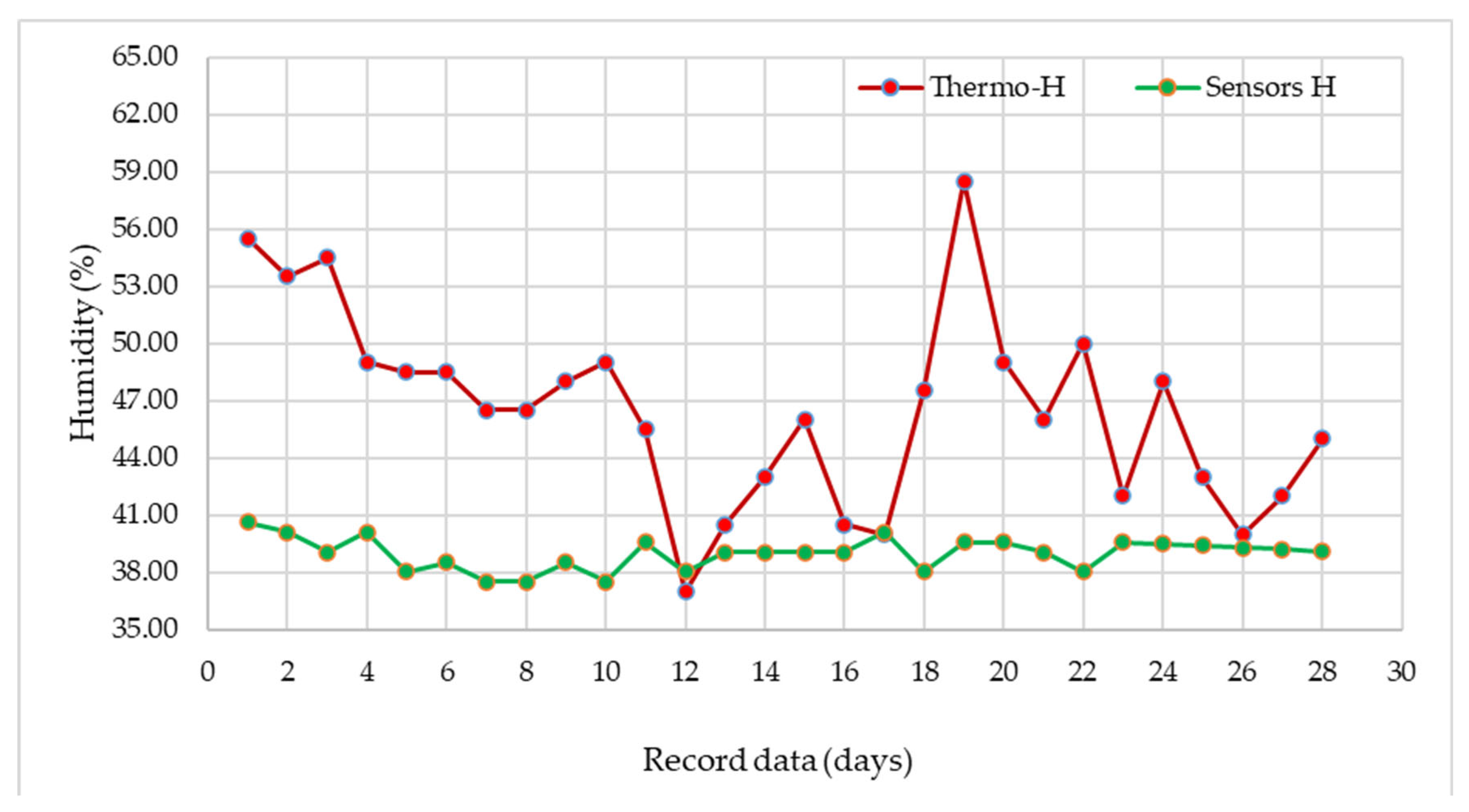
3.3. Accuracy, Sensitivity, and Response Time of Embedded Sensors

The instrumentation of structural molds with embedded sensors allowed for accurate monitoring of the internal temperature and humidity of the concrete during curing. The sensors were installed immediately after pouring the concrete into the slab molds (positions P1 and P2) and column (C1), as shown in Figure 6.
The DS18B20 (temperature) and HD-38 (humidity) sensors performed stably throughout the process. The readings showed deviations of less than ±0.6 °C in temperature and ±4% in relative humidity, even in the face of external climatic variations. This high accuracy and sensitivity made it possible to detect risk conditions that could lead to microcracks, thus contributing to the prevention and early rehabilitation of cracks.
Figure 12 shows the electronic circuit that includes Arduino, LCD screen, RCL devices, and thermohygrometer equipment, which allowed for automated real-time reading. The correlation between internal readings and compressive strength tests is also evident, strengthening the comparative structural analysis.
Thermal differences of up to 20 °C were detected between the shaded (P1) and exposed (P2) areas on the slab, affecting evaporation and moisture content. The column, due to its compact geometry, retained more moisture. These thermal–hygrometric variations were key to anticipating vulnerable areas and activating localized automated curing mechanisms.
Overall, the results validate the system as an effective diagnostic and control tool, integrating embedded sensors under controlled conditions to optimize the response of concrete to environmental factors and reduce the formation of surface or internal cracks.

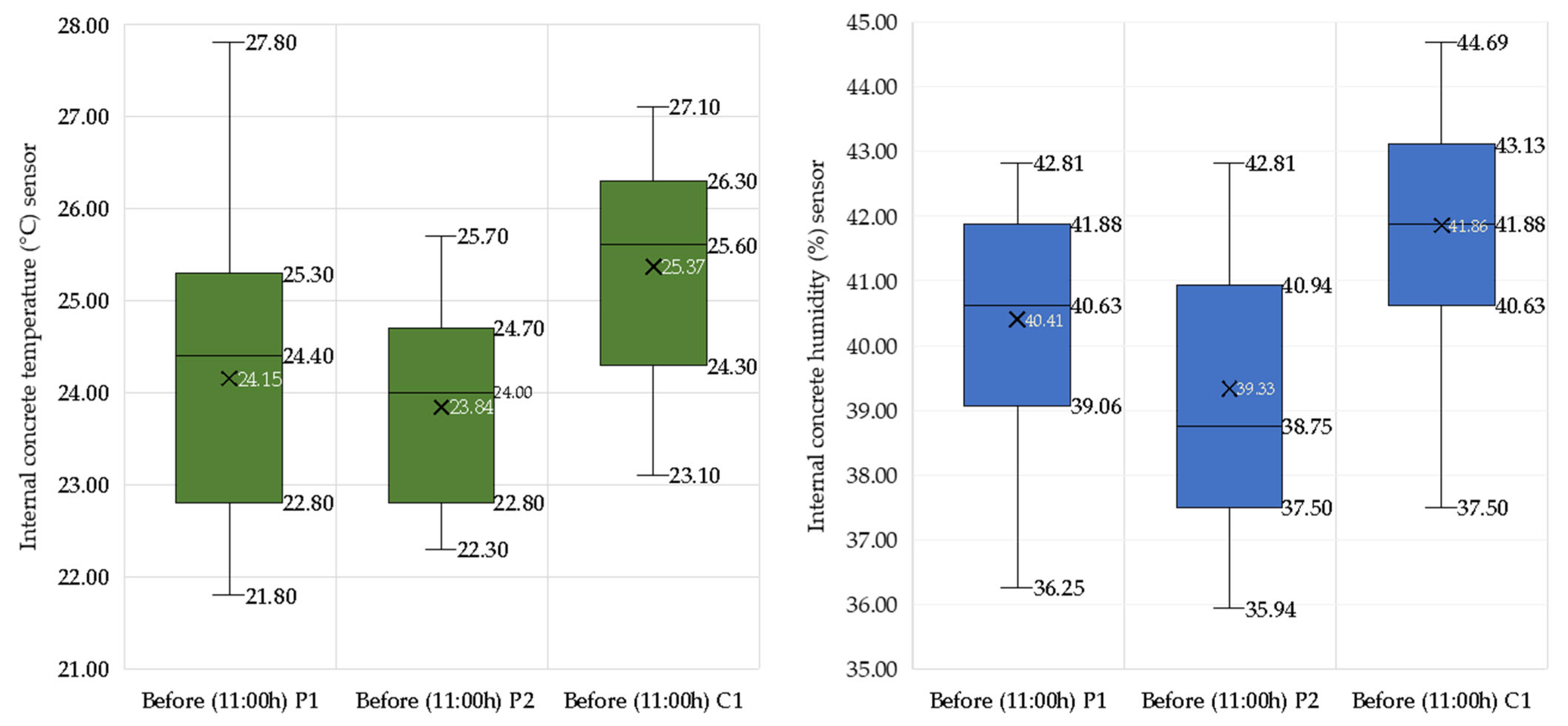
3.4. Internal Thermal and Hygrometric Analysis of Concrete

The Shapiro–Wilk normality test was applied to the temperature and humidity data recorded on days 1–7, 8–14, 15–21, and 22–28, yielding p-values of 0.146, 0.204, 0.975, and 0.806, respectively. Since all exceed the significance threshold (p > 0.05), the normal distribution of the data is confirmed, which validates the use of parametric tests.
Statistical analyses revealed significant differences between the thermohygrometer readings and the embedded sensors. For temperature, the difference in means was 2.36 °C (p = 0.000; 95% CI: [1.852–2.865]), and for relative humidity, it was 7.54% (p = 0.000; 95% CI: [5.59–9.49]). The high t-values (9.550 and 7.928, respectively) reinforce the significance of these findings.
These results highlight the effectiveness of the embedded sensor system, programmed on Arduino platforms, as a key tool for monitoring the internal conditions of concrete under an automated curing approach.
Figure 13 shows that the internal temperature of the concrete increased progressively from the third day onwards, while the ambient temperature remained more stable, confirming that cement hydration internally regulates the thermal process. The Pearson correlation between the two was r = 0.587 (p = 0.001), indicating a moderate and significant relationship.
The initial internal relative humidity was 45%, then showed a more stable downward trend compared to the high external variability, as shown in Figure 14. The correlation between internal and external humidity was r = 0.143 (p = 0.468), indicating a weak and insignificant relationship. This shows that the hygrometric behavior of concrete depends mainly on its internal structure and not on the environmental conditions. This finding reinforces the importance of embedded monitoring under controlled conditions to anticipate moisture losses that can trigger microcracks.
The box plots (Figure 15) show an inverse relationship between temperature and humidity. Between 11:00 A.M. and 2:00 P.M., the temperature rose to 33.85 °C, reducing the humidity to 37.96%, confirming the thermal effect on evaporation, in accordance with Clausius–Clapeyron’s law.
Figure 16 and Figure 17 show the thermal and hygrometric behavior in two hourly intervals. Before 11:00 A.M., the internal temperature remained stable (23.84–25.37 °C) and the humidity was between 39.33% and 41.86%. During peak hours, the internal temperatures remained below the ambient temperature, while the humidity gradually decreased (36.06–38.94%).
The integration of the embedded sensors under an automated curing system allowed these variations to be detected in real time, generating essential data for the preventive rehabilitation of cracks in concrete exposed to extreme conditions. Structural factors such as slab thickness, density, and water/cement ratio influenced the efficiency of curing, validating the proposed approach.

3.5. Crack Formation and Detection Using Embedded Monitoring

During the curing of concrete in a solid slab, the evaporation rate (E) was calculated under environmental conditions of 30 °C, 4 m/s wind, and 35% relative humidity. Using a coefficient K = 0.01, a thermal resistance R = 100 s/m, Ps = 4.243 kPa, and Pa = 1.5 kPa, the corresponding equation yielded a value of E = 0.00010972 L/s. This is equivalent to a loss of approximately 1.097 mL/s over 4 m2 of exposed surface area, which can cause surface cracking if not adequately compensated for (Figure 18).
This calculation, processed and recorded automatically by the embedded electronic system, demonstrates how controlled monitoring can predict critical cracking conditions.
The curve of variation in the rate of surface evaporation of water in concrete was calculated under tropical environmental conditions with high solar radiation. It can be seen that evaporation peaks between 11:00 and 16:00 (UTC-5), increasing the risk of cracking due to accelerated drying in the absence of adequate curing.
Table 2 details the critical moment of cracking, which occurred two hours after pouring, with a temperature of 29.9 °C and 54% relative humidity. The first crack, transverse and visible in the center of the slab, had an opening of 0.01 mm. This phenomenon was detected by embedded sensors integrated into an automated system controlled by microcontrollers, which allowed it to be linked to factors such as accelerated evaporation, drying shrinkage, thermal expansion, and mix quality.
The table allows us to identify the direct relationship between surface evaporation, climatic conditions, and the early appearance of transverse cracks in the slab.
The architecture of the Arduino system, with an electrovalve and embedded sensors, allowed for the accurate, real-time recording of the sequence between pouring, sensor installation, the onset of cracking, and activation of the automated curing system. This monitoring showed how surface water loss, if not controlled, generates internal stresses that induce cracks and compromise structural durability.
These results validate the use of embedded monitoring and electronic automation as effective scientific tools for preventing, detecting, and repairing cracks in concrete exposed to extreme weather conditions.

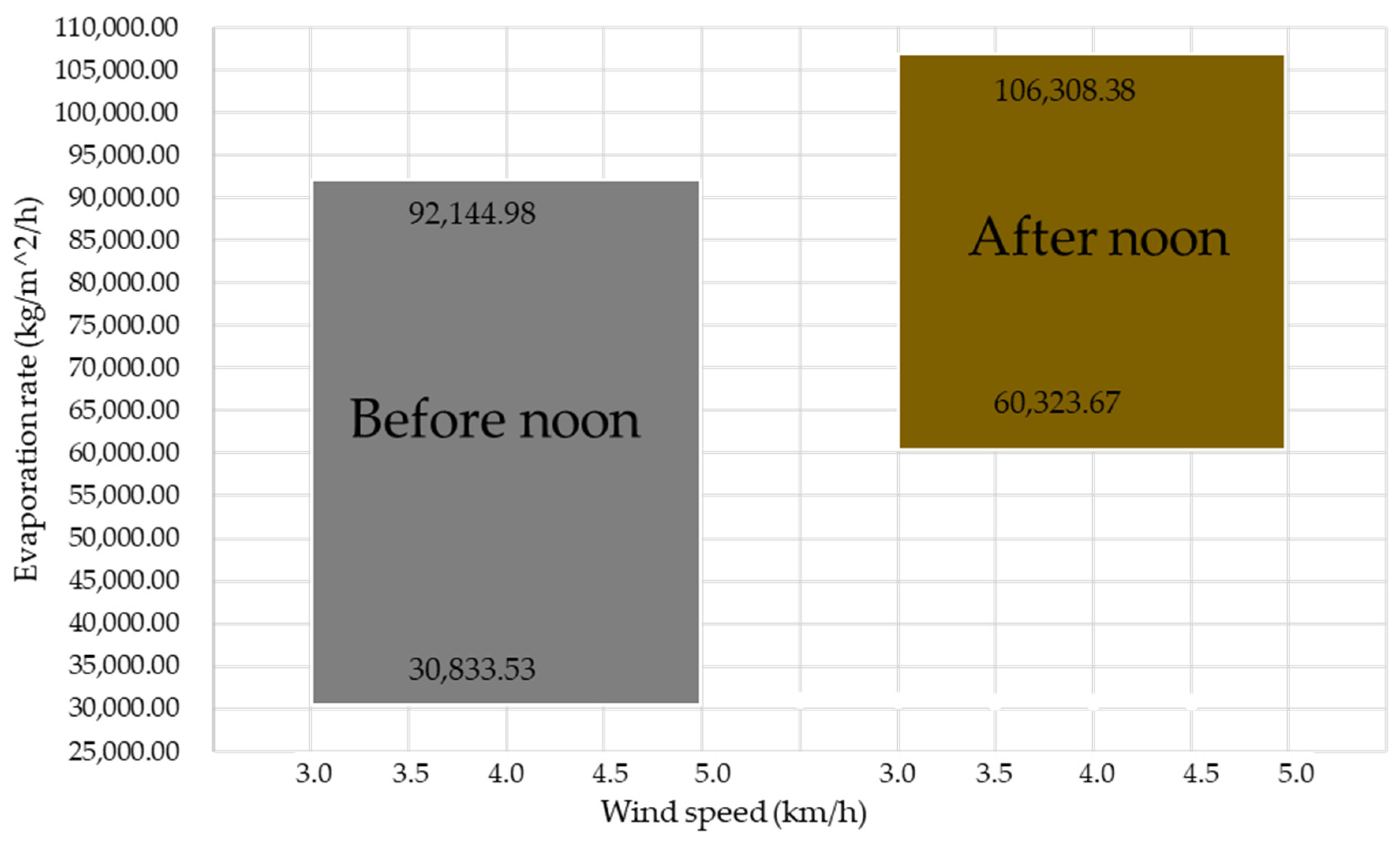
3.6. Efficiency of the Automated Irrigation System in Curing

The automated curing system, activated by programmed electronic controllers, demonstrated high water efficiency on a 4 m2 solid slab. Applying Torricelli’s equation, an output flow rate of 0.254 L/s was estimated in a 1/2-inch pipe, allowing 2 L of water to be applied in a time between 7.87 and 15.87 s, depending on the actual flow velocity.
The cylindrical tank, with a height of 1.65 m and a radius of 0.775 m, has an approximate capacity of 3110 L. Table 3 details the amount of water required for daily curing for 28 days, accumulating a total consumption of 1680 L. Automated management using embedded sensors and Arduino-controlled solenoid valves allowed the water supply to be optimized according to the curing phases.
Distribution of the volume of water used at different curing intervals, considering two daily waterings. The frequency, duration, and accumulated volume are detailed, reaching a total of 1680 L for a 4 m2 solid slab, which optimizes water use according to the curing stages. Optimal daytime curing reduces water consumption, optimizing its use in construction and promoting sustainable water resource management.
Table 4 shows the performance of the solenoid valve, which operated for 5.83 h in one week. It was evident that as the watering interval increased, the activation frequency and daily watering time decreased, reflecting an optimization in water and energy use based on the integrated electronic control.
It shows how adjusting the intervals reduces the activation frequency and improves the operational performance of the system.
This precise and programmable control of the water supply, thanks to embedded sensors and the Arduino UNO board, contributes directly to the effective rehabilitation of concrete during the curing process, preventing surface cracking associated with dehydration.
In addition, the use of non-potable sources or treated water is recommended, contributing to water sustainability in civil works through the rational use of resources and the integration of low-energy electronic technologies.

3.7. Validation of the Elevated Tank as Part of the Automatic Curing System

The installation of the elevated tank 1 m above the slab, with a water height of 1.65 m and a diameter of 1.55 m, allowed an outlet pressure of 26 kPa and a flow rate of 0. 916 L/s (according to Equation (4)), which ensured a continuous and controlled supply of water for automated concrete curing. The sprinkler system, directed between 90° and 360°, distributed the water evenly through valves and hoses connected to an Arduino-based embedded controller, configured to operate without manual intervention.
The structural base of the tank was designed to support a load of 2500 L (equivalent to 25 kN) and was installed on a level and firm platform, ensuring its stability. The automated system operated in programmed cycles of 8 s every 30 min, with a weekly variable irrigation frequency, responding to temperature and humidity conditions monitored by embedded sensors.
Diagram of the automated curing system, consisting of an elevated tank, solenoid valve, and Arduino module. The tank supplies water by gravity, while the electronic controller regulates the irrigation cycles. This system integrates the use of embedded sensors to adjust the water supply based on the internal conditions of the concrete, helping to prevent surface dehydration and crack formation.
The use of the elevated tank as a component of the embedded system ensures operational autonomy, water efficiency, and effective concrete rehabilitation during the curing process.

4. Discussion

The results obtained validate the main hypothesis: the use of embedded sensors and electronic controllers significantly improves concrete curing by reducing crack formation and optimizing water use. The compression tests showed a progressive evolution of strength, from 9.13 MPa to 18.87 MPa between days 7 and 21, projecting 20 MPa at 28 days. This behavior complies with international standards such as ASTM C39 and RNE E.060, attributed to automated control during curing.
The integration of DS18B20 (temperature) and HD-38 (humidity) sensors, validated in simulations and physical tests, provided stable and accurate readings (±0.6 °C and ±4% RH). The low correlation between ambient and internal humidity (r = 0.143) showed that hygrometric regulation depends mainly on the internal microclimate of the concrete, which justifies the use of embedded sensors for localized monitoring [80].
The highest evaporation rate (1.097 mL/s in 4 m2) was detected between 11:00 A.M. and 4:00 P.M., generating visible surface cracks of 0.01 mm in the first few hours. The automated system responded by activating irrigation cycles every 30–75 min, using 1680 L in 28 days, reducing consumption by 20% compared to traditional methods.
The inclusion of an elevated tank (1 m) with a pressure of 26 kPa and a flow rate of 0.916 L/s allowed for a constant, uniform flow without human intervention. The total operation of the solenoid valve (5.83 h/week) demonstrated high energy and water efficiency.
Overall, this embedded technology not only allows for the early detection of critical conditions, but also acts preventively, improving structural durability in tropical environments, where traditional curing is limited and ineffective [81,82].
Recent findings suggest that additives such as dimethylamine can enhance CO2 uptake in cement, contributing to both curing efficiency and sustainability [83].

5. Conclusions

The automated curing system with embedded sensors (DS18B20 and HD-38) and electronic controllers (Arduino UNO) demonstrated high functional efficiency, allowing the real-time monitoring of the internal temperature and humidity of the concrete with deviations of less than ±0.6 °C and ±4%. This precision was key to preventing surface cracking due to accelerated drying, especially in tropical environments.
The test specimens reached compressive strengths of 18.87 MPa at 21 days, with a logarithmic projection to 20 MPa at 28 days, meeting RNE E.060, NTP 334.090, and ASTM C39 standards. This validates that automated curing improves the mechanical properties of concrete under controlled conditions.
The thermal and hygrometric analysis revealed that concrete maintains more stable internal conditions than the environment, with little influence from ambient humidity (r = 0.143) and moderate correlation for temperature (r = 0.587). This autonomy confirms that embedded monitoring allows for the effective management of the internal microclimate.
The system detected surface cracks of 0.01 mm two hours after pouring, related to evaporation rates of 1.097 mL/s in 4 m2. This early diagnosis allows for immediate corrective measures to be taken.
Automated irrigation, regulated by solenoid valves and cycles controlled by Arduino, consumed 1680 L in 28 days, with only 5.83 h of operation per week. The elevated tank (1 m), with a pressure of 26 kPa and a flow rate of 0.916 L/s, ensured autonomous supply and uniform coverage of 90–360° without human intervention.
Overall, the results confirm that the use of embedded and controlled sensors under controlled conditions allows for the detection, anticipation, and correction of crack formation, optimizing the strength, durability, and sustainability of concrete in extreme climates.

Author Contributions

P.P.A.G.: Writing (proofreading and editing), writing (original draft), and research. G.E.O.C.: monitoring and validation. W.M.Z.Z.: project management. M.A.A.C.: conceptualization. W.R.P.: formal analysis and visualization. E.J.C.R.: data curation and methodology. H.M.M.R.: acquisition of financing and resources. N.A.F.: software. All authors have read and agreed to the published version of the manuscript.

Funding

This research was funded by the Universidad Nacional Intercultural Fabiola Salazar Leguía de Bagua (UNIFSLB) grant number [7,000.00].

Institutional Review Board Statement

This research was developed under strict ethical principles, prioritizing respect for the participants’ autonomy, beneficence, and justice. National and international regulations in force were complied with, as well as the provisions of the Code of Ethics of the Institutional Ethics Committee and the Bases of the UNIFSLB 2024 Teaching Competition, ensuring scientific integrity and respect for the rights of all those involved.

Informed Consent Statement

Not applicable.

Data Availability Statement

Data are available upon request to the corresponding author.

Acknowledgments

I express my deep gratitude to the Universidad Nacional Intercultural Fabiola Salazar Leguía of Bagua, Amazonas, Peru, for providing access to its equipment and laboratories, which were essential for the experimental tests and sample analysis. I also acknowledge their valuable financial support, granted through institutional competitions, which made possible the partial development of this research. I also extend my gratitude to my collaborators and to the external researchers, whose contributions, comments, and suggestions were essential to achieving the expected results in a satisfactory manner.

Conflicts of Interest

The authors declare that there are no financial conflicts or personal relationships that could have affected the development or presentation of the content of this article.

References

  1. Burlacu, A.; Sosoi, G.; Abid, C.; Barbuta, M.; Verdes, M.; Vizitiu, R.S.; Branoaea, M. Innovative Passive and Environmentally Friendly System for Improving the Energy Performance of Buildings. Materials 2022, 15, 7224. [Google Scholar] [CrossRef] [PubMed]
  2. Común, E.; Sanabria, A.; Mosquera, L.; Torre, A. Application of self-curing concrete method using polyethylene glycol. In Proceedings of the LACCEI International Multi-Conference for Engineering, Education and Technology, Virtual, 27–31 July 2020. [Google Scholar] [CrossRef]
  3. Jahani, Y.; Baena, M.; Barris, C.; Perera, R.; Torres, L. Influence of curing, post-curing and testing temperatures on mechanical properties of a structural adhesive. Constr. Build Mater. 2022, 324, 126698. [Google Scholar] [CrossRef]
  4. Al Mughairi, M.; Beach, T.; Rezgui, Y. Post-occupancy evaluation for enhancing building performance and automation deployment. J. Build. Eng. 2023, 77, 107388. [Google Scholar] [CrossRef]
  5. Younis, Z.A.; Nazari, M. Optimizing Sustainability of Concrete Structures Using Tire-Derived Aggregates: A Performance Improvement Study. CivilEng 2024, 5, 30–40. [Google Scholar] [CrossRef]
  6. Lou, B.; Ma, F. Evolution on fracture properties of concrete during steam curing. Case Stud. Constr. Mater. 2022, 16, e01105. [Google Scholar] [CrossRef]
  7. Baek, S.H.; Lee, K.I.; Kim, S.M. Development of Real-Time Monitoring System Based on IoT Technology for Curing Compound Application Process during Cement Concrete Pavement Construction. Sensors 2023, 23, 8187. [Google Scholar] [CrossRef]
  8. Joshaghani, A.; Balapour, M.; Ramezanianpour, A.A. Effect of controlled environmental conditions on mechanical, microstructural and durability properties of cement mortar. Constr. Build Mater. 2018, 164, 134–149. [Google Scholar] [CrossRef]
  9. Alyousef, R.; Abbass, W.; Aslam, F.; Gillani, S.A.A. Characterization of high-performance concrete using limestone powder and supplementary fillers in binary and ternary blends under different curing regimes. Case Stud. Constr. Mater. 2023, 18, e02058. [Google Scholar] [CrossRef]
  10. Shi, J.; Liu, B.; Zhou, F.; Shen, S.; Guo, A.; Xie, Y. Effect of steam curing regimes on temperature and humidity gradient, permeability and microstructure of concrete. Constr. Build Mater. 2021, 281, 122562. [Google Scholar] [CrossRef]
  11. Souza, E.; Pinheiro, P.; Coutinho, F.; Dias, J.; Pilar, R.; Pontes, M.J.; Leal-Junior, A. Smart Concrete Using Optical Sensors Based on Bragg Gratings Embedded in a Cementitious Mixture: Cure Monitoring and Beam Test. Sensors 2024, 24, 7998. [Google Scholar] [CrossRef]
  12. Ikumi, T.; Cairó, I.; Groeneveld, J.; Aguado, A.; de la Fuente, A. Embedded Wireless Sensor for In Situ Concrete Internal Relative Humidity Monitoring. Sensors 2024, 24, 1756. [Google Scholar] [CrossRef] [PubMed]
  13. Yang, J.; Fan, J.; Kong, B.; Cai, C.; Chen, K. Theory and application of new automated concrete curing system. J. Build. Eng. 2018, 17, 125–134. [Google Scholar] [CrossRef]
  14. Martinelli, E.; Pepe, M.; Lima, C.; Iacono, S.D.; Ferro, M.; Paciello, V.; Sommella, P. Pseudo-Adiabatic Concrete Curing Monitoring IoT-Enabled System. In Proceedings of the 2023 IEEE International Workshop on Metrology for Industry 4.0 and IoT, MetroInd4.0 and IoT 2023, Brescia, Italy, 6–8 June 2023. [Google Scholar] [CrossRef]
  15. RNE, Reglamento Nacional de Edificaciones RNE, Norma E.060. Peru. 2024. Available online: https://www.gob.pe/institucion/vivienda/informes-publicaciones/2309793-reglamento-nacional-de-edificaciones-rne (accessed on 22 June 2025).
  16. NTP 334.090; Norma Técnica Peruana. INDECOPI: Lima, Peru, 2011.
  17. Astm C39/C39M; Standard Test Method for Compressive Strength of Cylindrical Concrete Specimens. ASTM International: West Conshohocken, PA, USA, 2001.
  18. Cataldo, A.; Schiavoni, R.; Masciullo, A.; Cannazza, G.; Micelli, F.; De Benedetto, E. Combined punctual and diffused monitoring of concrete structures based on dielectric measurements. Sensors 2021, 21, 4872. [Google Scholar] [CrossRef] [PubMed]
  19. Tareen, N.; Kim, J.; Kim, W.K.; Park, S. Fuzzy logic-based and nondestructive concrete strength evaluation using modified carbon nanotubes as a hybrid pzt–cnt sensor. Materials 2021, 14, 2953. [Google Scholar] [CrossRef]
  20. Taffese, W.Z.; Nigussie, E. Automated concrete curing and assessment of strength and durability using IoT system. Mater. Today Proc. 2023. [Google Scholar] [CrossRef]
  21. Wang, T.; Gao, X.; Li, Y.; Liu, Y. An orthogonal experimental study on the influence of steam-curing on mechanical properties of foam concrete with fly ash. Case Stud. Constr. Mater. 2024, 20, e02665. [Google Scholar] [CrossRef]
  22. Donadello, I.; Di Francescomarino, C.; Maggi, F.M.; Ricci, F.; Shikhizada, A. Outcome-Oriented Prescriptive Process Monitoring based on Temporal Logic Patterns. Eng. Appl. Artif. Intell. 2023, 126, 106899. [Google Scholar] [CrossRef]
  23. Liu, W.; He, S.; Mou, J.; Xue, T.; Chen, H.; Xiong, W. Digital twins-based process monitoring for wastewater treatment processes. Reliab. Eng. Syst. Saf. 2023, 238, 109416. [Google Scholar] [CrossRef]
  24. Huang, L.; Tang, L.; Löfgren, I.; Olsson, N.; Babaahmadi, A.; Esping, O.; Li, Y.; Yang, Z. Non-destructive test system to monitor hydration and strength development of low CO2 concrete. Constr. Build. Mater. 2023, 408, 133774. [Google Scholar] [CrossRef]
  25. Babu, J.C.; Kumar, M.S.; Jayagopal, P.; Sathishkumar, V.E.; Rajendran, S.; Kumar, S.; Karthick, A.; Mahseena, A.M.; Ahmed, A. IoT-Based Intelligent System for Internal Crack Detection in Building Blocks. J. Nanomater. 2022, 2022, 3947760. [Google Scholar] [CrossRef]
  26. Korda, E.; Tsangouri, E.; Snoeck, D.; De Schutter, G.; Aggelis, D.G. The sensitivity of Acoustic Emission (AE) for monitoring the effect of SAPs in fresh concrete. MATEC Web Conf. 2023, 378, 04006. [Google Scholar] [CrossRef]
  27. Reddy, V.M.; Hamsalekha, S.; Reddy, V.S. An IoT enabled real-time monitoring system for automatic curing and early age strength monitoring of concrete. AIP Conf. Proc. 2021, 2358, 080018. [Google Scholar] [CrossRef]
  28. Kim, S.; Jung, D.; Kim, J.Y.; Mun, J.H. Study on Early Age Concrete’s Compressive Strengths in Unmanaged Curing Condition Using IoT-Based Maturity Monitoring. Buildings 2024, 14, 798. [Google Scholar] [CrossRef]
  29. Bhavsar, D.; Limbasia, B.; Mori, Y.; Aglodiya, M.I.; Shah, M. A comprehensive and systematic study in smart drip and sprinkler irrigation systems. Smart Agric. Technol. 2023, 5, 100303. [Google Scholar] [CrossRef]
  30. Qian, J.; Zhang, P.; Wu, Y.; Jia, R.; Yang, J. Study on Corrosion Monitoring of Reinforced Concrete Based on Longitudinal Guided Ultrasonic Waves. Appl. Sci. 2024, 14, 1201. [Google Scholar] [CrossRef]
  31. Ziaja, D.; Jurek, M.; Wiater, A. Elastic Wave Application for Damage Detection in Concrete Slab with GFRP Reinforcement. Materials 2022, 15, 8523. [Google Scholar] [CrossRef] [PubMed]
  32. Feng, S.; Huang, Z.; Zhao, H. Doping dependence of Meissner effect in cuprate superconductors. Phys. C Supercond. Appl. 2010, 470, 1968–1976. [Google Scholar] [CrossRef]
  33. Wang, R.; Wu, H.; Zhao, M.; Liu, Y.; Chen, C. The Classification and Mechanism of Microcrack Homogenization Research in Cement Concrete Based on X-ray CT. Buildings 2022, 12, 1011. [Google Scholar] [CrossRef]
  34. Tang, Z.S.; Lim, Y.Y.; Smith, S.T.; Mostafa, A.; Lam, A.C.; Soh, C.K. Monitoring the curing process of in-situ concrete with piezoelectric-based techniques—A practical application. Struct. Health Monit. 2023, 22, 518–539. [Google Scholar] [CrossRef]
  35. Al Agha, W.; Pal, S.; Dev, N. Challenges for structural health monitoring of concrete curing using piezoelectric sensor and electromechanical impedance (EMI) technique: A critical review. Mater. Today Proc. 2023. [Google Scholar] [CrossRef]
  36. Guo, L.; Wang, W.; Zhong, L.; Guo, L.; Zhang, F.; Guo, Y. Texture analysis of the microstructure of internal curing concrete based on image recognition technology. Case Stud. Constr. Mater. 2022, 17, e01360. [Google Scholar] [CrossRef]
  37. Lo, K.-C.; Kwok, H.-W.T.; Siu, M.-F.F.; Shen, Q.G.; Lau, C.-K.; Liu, H. Internet of Things-Based Concrete Curing Invention for Construction Quality Control. Adv. Civ. Eng. 2021, 2021, 9933615. [Google Scholar] [CrossRef]
  38. Prakash, A.; Munipally, S.K.; Fernando, P.E. Fernando. Prediction of Concrete Constituents’ Behavior Using Internet of Things (IoT). Key Eng. Mater. 2023, 959, 161–170. [Google Scholar] [CrossRef]
  39. AMohamed, K.; Bouibes, A.; Bauchy, M.; Casar, Z. Molecular modelling of cementitious materials: Current progress and benefits. RILEM Tech. Lett. 2022, 7, 209–219. [Google Scholar] [CrossRef]
  40. Honrubia, M.M.; Domingo, J.M.; Herraiz-Martínez, F.J.; Giannetti, R. Low-Cost Electronics for Automatic Classification and Permittivity Estimation of Glycerin Solutions Using a Dielectric Resonator Sensor and Machine Learning Techniques. Sensors 2023, 23, 3940. [Google Scholar] [CrossRef]
  41. Komary, M.; Komarizadehasl, S.; Tošić, N.; Segura, I.; Lozano-Galant, J.A.; Turmo, J. Low-Cost Technologies Used in Corrosion Monitoring. Sensors 2023, 23, 1309. [Google Scholar] [CrossRef]
  42. Ptacek, L.; Strauss, A.; Hinterstoisser, B.; Zitek, A. Curing assessment of concrete with hyperspectral imaging. Materials 2021, 14, 3848. [Google Scholar] [CrossRef]
  43. Mohe, N.S.; Shewalul, Y.W.; Agon, E.C. Experimental investigation on mechanical properties of concrete using different sources of water for mixing and curing concrete. Case Stud. Constr. Mater. 2022, 16, e00959. [Google Scholar] [CrossRef]
  44. Zeyad, A.M.; Tayeh, B.A.; Adesina, A.; de Azevedo, A.R.; Amin, M.; Hadzima-Nyarko, M.; Agwa, I.S. Review on effect of steam curing on behavior of concrete. Clean. Mater. 2022, 3, 100042. [Google Scholar] [CrossRef]
  45. Wang, H.; Guo, B.; Guo, Y.; Jiang, R.; Zhao, F.; Wang, B. Effects of Curing Methods on the Permeability and Mechanism of Cover Concrete. J. Build. Mater. Sci. 2023, 5, 20–31. [Google Scholar] [CrossRef]
  46. Zeyad, A.M.; Johari, M.A.M.; Alharbi, Y.R.; Abadel, A.A.; Amran, Y.M.; Tayeh, B.A.; Abutaleb, A. Influence of steam curing regimes on the properties of ultrafine POFA-based high-strength green concrete. J. Build. Eng. 2021, 38, 102204. [Google Scholar] [CrossRef]
  47. Wang, X.; Wang, G.; Gong, F.; Qin, L.; Gao, Z.; Cheng, X. Evaluation and Analysis of Asphalt Concrete Density Based on Core Samples. J. Mater. Civ. Eng. 2024, 36, 04023523. [Google Scholar] [CrossRef]
  48. Kumar, A.; Saxena, S.; Rawat, V.S. Effect of Various Methods of Curing on Concrete Using Crusher Dust as Replacement to Natural Sand. Macromol. Symp. 2024, 413, 2200211. [Google Scholar] [CrossRef]
  49. Liu, Z.; Liu, G.; Zhang, G. Effect of Curing Time on the Surface Permeability of Concrete with a Large Amount of Mineral Admixtures. Adv. Civ. Eng. 2022, 2022, 1034388. [Google Scholar] [CrossRef]
  50. Jin, W.; Jiang, L.; Han, L.; Huang, H.; Zhi, F.; Yang, G.; Niu, Y.; Chen, L.; Wang, L.; Chen, Z. Influence of curing temperature on freeze-thaw resistance of limestone powder hydraulic concrete. Case Stud. Constr. Mater. 2022, 17, e01322. [Google Scholar] [CrossRef]
  51. Ahmed, H.U.; Mohammed, A.S.; Faraj, R.H.; Qaidi, S.M.A.; Mohammed, A.A. Compressive strength of geopolymer concrete modified with nano-silica: Experimental and modeling investigations. Case Stud. Constr. Mater. 2022, 16, e01036. [Google Scholar] [CrossRef]
  52. Wang, Y.; Zhu, J.; Guo, Y.; Wang, C. Early shrinkage experiment of concrete and the development law of its temperature and humidity field in natural environment. J. Build. Eng. 2023, 63, 105528. [Google Scholar] [CrossRef]
  53. Wang, J.; Li, H.; Ma, C.; Cai, C.; Wang, J. Effect of surface curing condition on the humidity field and moisture transfer in concrete. Constr. Build Mater. 2024, 411, 134701. [Google Scholar] [CrossRef]
  54. Poon, C.S.; Shui, Z.H.; Lam, L.; Fok, H.; Kou, S.C. Influence of moisture states of natural and recycled aggregates on the slump and compressive strength of concrete. Cem. Concr. Res. 2004, 34, 31–36. [Google Scholar] [CrossRef]
  55. Chauhdary, J.N.; Li, H.; Jiang, Y.; Pan, X.; Hussain, Z.; Javaid, M.; Rizwan, M. Advances in Sprinkler Irrigation: A Review in the Context of Precision Irrigation for Crop Production. Agronomy 2024, 14, 47. [Google Scholar] [CrossRef]
  56. Vu, C.-C.; Ho, N.-K. A comparative study on the probability distribution model for the compressive strength of concrete with consideration of the size effect. J. Eng. Res. 2024, 13, 1403–1413. [Google Scholar] [CrossRef]
  57. Li, D.; Tang, Z.; Kang, Q.; Zhang, X.; Li, Y. Machine Learning-Based Method for Predicting Compressive Strength of Concrete. Processes 2023, 11, 390. [Google Scholar] [CrossRef]
  58. Paudel, S.; Pudasaini, A.; Shrestha, R.K.; Kharel, E. Compressive strength of concrete material using machine learning techniques. Clean. Eng. Technol. 2023, 15, 100661. [Google Scholar] [CrossRef]
  59. Azarhomayun, F.; Haji, M.; Kioumarsi, M.; Shekarchi, M. Effect of calcium stearate and aluminum powder on free and restrained drying shrinkage, crack characteristic and mechanical properties of concrete. Cem. Concr. Compos. 2022, 125, 104276. [Google Scholar] [CrossRef]
  60. Jung, S.; Lee, S.; Yu, J. Ontological approach for automatic inference of concrete crack cause. Appl. Sci. 2021, 11, 252. [Google Scholar] [CrossRef]
  61. M’hammed, T.; Hamid, K. An experimental study on the influence of arid climate on early-age cracking of concrete—A case study of the city of Adrar in Algeria. AIMS Mater. Sci. 2021, 8, 200–220. [Google Scholar] [CrossRef]
  62. American Concrete Institute. ACI 305R-2—Guide to Hot Weather Concreting; American Concrete Institute: Farmington Hills, MI, USA, 2010; Volume ACI 305R-2, p. 2020. [Google Scholar]
  63. Habibbulloh, M.; Anggaryani, M.; Satriawan, M.; Saputra, O.; Zakaria, A.; Septiawan, F. Suitability of Torricelli’s Theorem Formulation in Cases of Leaking Reservoirs with Video Analysis Tracker. J. Phys. Conf. Ser. 2023, 2623, 012021. [Google Scholar] [CrossRef]
  64. Franchini, M.; Lanza, L. Use of Torricelli’s equation for describing leakages in pipes of different elastic materials, diameters and orifice shape and dimensions. Procedia Eng. 2014, 89, 290–297. [Google Scholar] [CrossRef]
  65. Nakayama, Y.; Boucher, R.F. Introduction to Fluid Mechanics; Butterworth-Heinemann: Oxford, UK, 1999. [Google Scholar]
  66. Ravasini, S.; Vecchi, F.; Belletti, B.; Muttoni, A. Verification of deflections and cracking of RC flat slabs with numerical and analytical approaches. Eng. Struct. 2023, 284, 115926. [Google Scholar] [CrossRef]
  67. Thompson, J.E.; Paluch, A.S. Revisiting the Clausius/Clapeyron Equation and the Cause of Linearity. Thermo 2023, 3, 412–423. [Google Scholar] [CrossRef]
  68. Marhasova, V.; Garafonova, O.; Deril, Z.; Rudenko, O. Scientific Research Methodology as A General Approach and Perspective Of The Research Process. Her. Khmelnytskyi Natl. Univ. Econ. Sci. 2022, 312, 328–334. [Google Scholar] [CrossRef] [PubMed]
  69. Oval, R.; Nuh, M.; Costa, E.; Madyan, O.A.; Orr, J.; Shepherd, P. A prototype low-carbon segmented concrete shell building floor system. Structures 2023, 49, 124–138. [Google Scholar] [CrossRef]
  70. Germann, C. Methodology and Empirical Research. In Chairperson Succession; Springer: Berlin/Heidelberg, Germany, 2023. [Google Scholar] [CrossRef]
  71. Vladlenov, D. Scientific Foundations in Research in Engineering; International Science Group: New York, NY, USA, 2022. [Google Scholar] [CrossRef]
  72. Silaban, R.S. Analisa Struktur Bangunan Rumah Susun MBR Type—36 (3 Lantai) Prototype Pada Wilayah Gempa Dan Non Gempa Study Kasus Rusun MBR Pemkab Kotim. Media Ilm. Tek. Sipil 2023, 11, 58–67. [Google Scholar] [CrossRef]
  73. Young, M.D.; Diem, S. Handbook of Critical Education Research: Qualitative, Quantitative, and Emerging Approaches; Routledge: New York, NY, USA, 2023. [Google Scholar] [CrossRef]
  74. Li, Y. Research Methodology. In Educational Change Amongst English Language College Teachers in China; Springer: Singapore, 2020. [Google Scholar] [CrossRef]
  75. ISO 1920-10; Testing of Concrete: Determination of Static Modulus of Elasticity in Compression. ISO: Geneva, Switzerland, 2010. Available online: https://www.iso.org/standard/51829.html (accessed on 22 June 2025).
  76. Yang, J. An empirical survey of statistical research methods in applied science. J. King Saud. Univ. Sci. 2022, 34, 102008. [Google Scholar] [CrossRef]
  77. Bustamante, S. Research Methodology and Procedure. In CSR, Sustainability, Ethics and Governance; Springer: Berlin/Heidelberg, Germany, 2021. [Google Scholar] [CrossRef]
  78. Moed, H.F.; Glänzel, W.; Schmoch, U. Handbook of Quantitative Science and Technology Research; Springer: Berlin/Heidelberg, Germany, 2005. [Google Scholar] [CrossRef]
  79. Mishra, M.; Lourenço, P.B.; Ramana, G.V. Structural health monitoring of civil engineering structures by using the internet of things: A review. J. Build. Eng. 2022, 48, 103954. [Google Scholar] [CrossRef]
  80. Khan, A.-M.; Kee, S.-H.; Pathan, A.-S.K.; Nahid, A.-A. Image Processing Techniques for Concrete Crack Detection: A Scientometrics Literature Review. Remote Sens. 2023, 15, 2400. [Google Scholar] [CrossRef]
  81. Levchenko, A.; Polikutin, A.; Barabash, D. Crack resistance of reinforced concreted and reinforced rubber concrete beams. Arch. Tech. Sci. 2020, 1, 21–26. [Google Scholar] [CrossRef]
  82. Filho, J.R.T.; Abbas, Y.; Oudenhoven, J.; Matthys, S. Application of Cost Effective and Real-Time Resistivity Sensor to Study Early Age Concrete. Sensors 2023, 23, 7525. [Google Scholar] [CrossRef]
  83. Xu, M.; Zhang, Q.; Zhou, S.; Li, S.; Li, Y.; Wu, C. Enhanced CO2 uptake of cement pastes incorporated with dimethylamine: Mechanisms and effects on microstructure and strength. Innov. Infrastruct. Solut. 2024, 10, 15. [Google Scholar] [CrossRef]
Figure 1. Distribution of theoretical bases (adapted from [18,19]).
Technologies 13 00284 g001
Figure 2. Flow diagram of the smart system.
Technologies 13 00284 g002
Figure 4. Three-dimensional experimental structural model and sensor locations.
Technologies 13 00284 g004
Figure 5. Initial stage of the experimental process: (a) pouring the concrete, (b) immersing the sensor in the column, and (c) placing sensors in the fresh slab.
Technologies 13 00284 g005
Figure 6. Sensor installation: (a) at position P1, (b) at position P2, and (c,d) in column C1.
Technologies 13 00284 g006
Figure 7. Electronic circuit design. The lines indicate: green, data bus between Arduino and LCD; red, 5V power supply; black, ground connection; purple, humidity sensor data bus; and blue, temperature sensor data bus.
Technologies 13 00284 g007
Figure 8. Real-time concrete curing electronic circuit.
Technologies 13 00284 g008
Figure 9. Diagram of the elevated tank and electronic control circuit.
Technologies 13 00284 g009
Figure 10. Sequence of methodology developed.
Technologies 13 00284 g010
Figure 11. Compressive strength result of the sample (test specimen).
Technologies 13 00284 g011
Figure 12. Electronic circuit with embedded devices.
Technologies 13 00284 g012
Figure 13. Ambient and internal thermal variability of concrete during curing.
Technologies 13 00284 g013
Figure 14. Relative ambient and internal hygrometric behavior in concrete.
Technologies 13 00284 g014
Figure 15. Hourly distribution of temperature and relative humidity (boxplots).
Technologies 13 00284 g015
Figure 16. Internal thermal and hygrometric behavior before 11:00 A.M.
Technologies 13 00284 g016
Figure 17. Internal thermal and hygrometric behavior between 11:00 A.M. and 4:00 P.M.
Technologies 13 00284 g017
Figure 18. Range of water evaporation in concrete during curing.
Technologies 13 00284 g018
Table 1. Arduino algorithm (sensors, LDC, and solenoid valve).
Coding of Humidity Sensor HD-38, LCD, and ARDUINOCoding of DS18B20 Temperature Sensor, LCD, and ArduinoSolenoid Valve Coding (Automation) and Arduino
(1)
#include <OneWire.h>
(2)
#include <LiquidCrystal.h>
(3)
LiquidCrystal lcd(12, 11, 5, 4, 3, 2);
(4)
int SensorPin = A0;
(5)
int Concrete = 0;
(6)
void setup() {
(7)
pinMode(7, OUTPUT);
(8)
lcd.begin(16, 2);
(9)
lcd.print(“Indoor Humidity”);
(10)
Serial.begin(9600);
(11)
}
(12)
void loop() {
(13)
int Humidity = analogRead(SensorPin);
(14)
Serial.println(Humidity);
(15)
if (Humidity >= 870) {
(16)
digitalWrite(7, LOW);
(17)
} else {
(18)
digitalWrite(7, HIGH);
(19)
}
(20)
int Concrete = analogRead(SensorPin);
(21)
Concrete = constrain(Concrete, 0, 876);
(22)
Concrete = map(Concrete, 0, 876, 0, 100);
(23)
Serial.print(“Indoor Humidity:”);
(24)
Serial.println(Concrete);
(25)
lcd.setCursor(5, 1);
(26)
lcd.print(Concrete);
(27)
lcd.print(“%”);
(28)
delay(1000);
(29)
lcd.print(““);
(30)
delay(1000);
(31)
}
(1)
#include <LiquidCrystal_I2C.h>
(2)
#include <Wire.h>
(3)
#include <OneWire.h>
(4)
#include <DallasTemperature.h>
(5)
OneWire ourWire(9);
(6)
DallasTemperature sensors(&ourWire);
(7)
LiquidCrystal_I2C lcd(0x27, 16, 2);
(8)
void setup() {
(9)
Serial.begin(9600);
(10)
sensors.begin();
(11)
lcd.init();
(12)
lcd.backlight();
(13)
lcd.clear();
(14)
delay(1000);
(15)
}
(16)
void loop() {
(17)
sensors.requestTemperatures();
(18)
float temp = sensors.getTempCByIndex(0);
(19)
lcd.setCursor(2, 0);
(20)
lcd.print(“Temperature:”);
(21)
lcd.setCursor(1, 1);
(22)
lcd.print(temp);
(23)
lcd.setCursor(6, 1);
(24)
lcd.print((char)223);
(25)
lcd.setCursor(5, 1);
(26)
lcd.print(“ “);
(27)
lcd.setCursor(7, 1);
(28)
lcd.print(“C”);
(29)
Serial.print(“Temperature= “);
(30)
Serial.println(temp);
(31)
delay(1000);
(32)
}
(1)
#include <LiquidCrystal.h> double Temp;
(2)
int Setpoint;
(3)
LiquidCrystal lcd(12,11,5,4,3,2);
(4)
const int SetTempDown = 8;
(5)
int TemButtonCounter = 20;
(6)
int TempButtonUpState = 0;
(7)
int TempButtonDownState = 0;
(8)
int lastTempButtonState = 0;
(9)
void setup(){
(10)
lcd.begin(16,2);
(11)
pinMode(SetTempUp, INPUT);
(12)
pinMode(SetTempDown, INPUT);
(13)
pinMode(9,OUTPUT);
(14)
}
(15)
void loop(){
(16)
{Temp = analogRead(A0);
(17)
Temp = ((5.0 * Temp * 100.0)/1024.0);
(18)
delay(500);
(19)
lcd.setCursor(0,0);
(20)
lcd.print(“Temp: C”);
(21)
lcd.setCursor(10,0);
(22)
lcd.print((char)223);
(23)
lcd.setCursor(5,0);
(24)
lcd.print(Temp); }
(25)
{TempButtonUpState = digitalRead(SetTempUp);
(26)
if (TempButtonUpState = HIGH){ TemButtonCounter++; }
(27)
} TempButtonDownState = digitalRead(SetTempDown);
(28)
if (TempButtonDownState = HIGH){ TemButtonCounter--;
(29)
} lcd.setCursor(0,1);
(30)
lcd.print(“Set:C”);
(31)
lcd.setCursor(6,1);
(32)
lcd.print((char)223);
(33)
lcd.setCursor(4,1);
(34)
lcd.print(TemButtonCounter);
(35)
}
Table 2. Sequence of events and environmental conditions at the time of crack formation.
Start and End of Pouring.Start and End of Installation.Cracks are Displayed (No).Cracks are Displayed (Yes).Spray Curing.Cracks are Displayed (No).T°C Variation.H% Variation.
17:00 a 18:2018:35 a 19:0019:4120:4020:40 a 20:4420:45 a 20:5028 a 29.953 a 54
Table 3. Amount of water required for the mode.
Curing Interval.Days.Irrigation Times (Per Day).Water (L).Total (L).
1 , 7 7482672
8 , 14 7362504
15 , 21 7242336
22 , 28 7122168
Amount of water used (L)1680
Table 4. Weekly operating time of the solenoid valve as a function of the irrigation interval.
Time It Takes to Repeat Watering (Minutes).Time Taken to Water Each Repetition (Seconds).Number of Watering Times (Per Day).Watering Time Per Day (Seconds).Total Watering Time in 7 Days.
3025481200140
452536900105
60252460070
75251230035
Working time of the solenoid valve (hours).5.83
Disclaimer/Publisher’s Note: The statements, opinions and data contained in all publications are solely those of the individual author(s) and contributor(s) and not of MDPI and/or the editor(s). MDPI and/or the editor(s) disclaim responsibility for any injury to people or property resulting from any ideas, methods, instructions or products referred to in the content.

