Article

Exploring the Failures of Deep Groove Ball Bearings Under Alternating Electric Current in the Presence of Commercial Lithium Grease

1
Tribology and Interactive Surfaces Research Laboratory (TRISUL), Department of Mechanical Engineering, Amrita School of Engineering, Amrita Vishwa Vidyapeetham, Chennai 601103, TN, India
2
Mechanical Engineering, Mechatronics and Robotics Department, “Gheorghe Asachi” Technical University of Iași, 43 Prof. Dimitrie Mangeron Blvd, 700050 Iasi, Romania
3
Department of Mechanical Engineering, Manipal University Jaipur, Jaipur 303007, RJ, India
4
Mosil Lubricants Private Limited, 166/1, “KALANIDHI”, Sion (West), Mumbai 400022, MH, India
*
Authors to whom correspondence should be addressed.
Technologies 2025, 13(7), 275; https://doi.org/10.3390/technologies13070275
Submission received: 23 April 2025 / Revised: 20 June 2025 / Accepted: 24 June 2025 / Published: 1 July 2025

Abstract

Deep groove ball bearings are important mechanical elements in the automotive and process industries, particularly in electric motors. One of the primary reasons for their failure is lubricant degradation due to stray shaft current. Thus, the present work exhibited the failure of bearings under simulated lubricated conditions similar to those of real time bearings failing in presence of stray electric current. The test was conducted using a full bearing test rig with an applied radial load, 496 N, an alternating current, 10 A, and a rotation of 2000 rpm for 24 h. The bearings (6206 series) were greased using two commercially available ester-polyalphaolefin oil-based greases with viscosity 46–54 cSt (Grease 1) and 32–35 cSt (Grease 2, also contained aromatic oil). The optical microscopic images of the bearing raceways after the tribo test indicated the superior performance of Grease 1 compared to Grease 2, with lesser formation of white etching areas, micro-pitting, spot welds, and fluting on the surfaces of the bearings. Additionally, 80% less vibrations were recorded during the test with Grease 1, indicating a stable lubricating film of Grease 1 during the test as compared to Grease 2. Furthermore, a higher extent of Grease 2 degradation during the tribo test was also confirmed using Fourier transform infrared spectroscopy. Statistical analysis (t-test) indicated the significant variation of the vibrations produced during the test with electrified conditions. The present work indicated that the composition of the greases plays a significant role in controlling the bearing failures.

1. Introduction

Traditional internal combustion engine (ICE) vehicles are gradually been replaced by electric vehicles (EVs), aiming towards a sustainable alternative [1]. Electric vehicles commonly utilize axial flux induction motors (AFIM) [2], permanent magnet synchronous motors (PMSM) [3], switched reluctance motors (SRM) [4], and brushless DC (BLDC) motors to convert electrical energy into mechanical energy [5]. It is well known that electric vehicles are becoming more efficient than internal combustion engines, but the energy losses in electric vehicles remain a major concern [6]. Despite the motor type, there is a current leakage [7], which has a potential risk of overloading the motor bearings and other drive components, making these components less reliable and causing the premature failure of the bearings [8,9]. Initially, these current leakages cause surface damage by arcing on a very small scale over the lubricating film [10,11]. The presence of parasitic current and stray current is the major reason to cause surface damage, such as corrugation patterns [12], electrical pitting [13], and pits on raceways and rolling elements. The stray electric current potentially originates from the power conversion process between the batteries and the electric motor via the inverter. When the accumulation of charges crosses the threshold point, it leads to the generation of plasma, which will vaporize and melt the metal surface. This is termed as electrically induced bearing damage (EIBD) [14]. As a result of EIBD, pitting develops, heat is generated, and embrittlement takes place, and thus surface fatigue and vibrations (noise) develop [15,16]. The vibrations produced also form a comprehensive indication of the health of the bearings [17]. Another important parameter that results in the premature bearing failure is shaft voltage [18]. Shaft voltage is present on the rotating shaft connected to the motor. This shaft voltage, caused by parasitic current [19], results in a current flow across the shaft due to the difference in the voltages between the shaft ends, and hence the motor bearings experience the electromechanical loads [20,21]. The presence of both mechanical and electrical loads on the bearing can also cause surface damage like ablation pits [22] and three-body abrasion. When electrical current passes through the shaft, it flows through these bearings, exposing the lubricant to current; consequently, the bearing experiences electromechanical loads, which lead to significant wear and potential failure of the bearings [23]. Thus, the tribological contact under electromechanical loads leads to significant surface damage and increases the probability of lubricant loss through evaporation [24,25]. Bearings under high mechanical loads use greases for lubrication [26]; however, these traditional greases are not exposed to the stray current and shaft voltages. Thus, the service life of rolling bearings gets affected due to lubricant degradation, resulting in reduced film thickness, leading to contact between the tribo-pairs. To eliminate this disadvantage, it is necessary to select and use appropriate lubricants that eliminate high temperatures caused by local contacts and seals that prevent the ingress of impurities [27]. Due to the current passage, heat is generated from the lubricant as a response to the Joule Heating Effect [28]. The generated heat can reach beyond the breakdown temperature of traditional grease and evaporate the grease in the vicinity, causing metal–metal contact and resulting in current passage, leading to the premature failure of the bearing [29,30]. According to the Joule Heating Effect, the generated heat is directly proposed to the applied voltage, current, and duration of exposure [31]. During high voltage conditions, several bearings undergo a critical transition from a non-conductive to a conductive state [32,33]. The transition generally takes place due to two key processes. Firstly, the lubricants act as a capacitor storing electrical charge (non-conducting state); however, as the temperature rises it eventually exceeds the breakdown temperature and causes the lubricant to degrade, allowing electric charges to pass through the bearing (conductive state) [34]. Secondly, the thickness of the lubricant film also plays a crucial role in the transition. A high-thickness film acts as a capacitor, while a low-thickness film behaves more like a resistor. The voltage needed for this transition depends upon the pressure in the vicinity and the rotation speed of the bearing, which was observed using an oscilloscope in a full bearing test [35]. As the lubricant film thickness decreases, the increased pressure or the high rotating speed facilitates the flow of current through the bearing. Lubricant manufacturing industries are formulating effective lubricants that can be used in electric vehicles to mitigate and overcome the premature failure of the bearings due to electromechanical loads [36]. Grease parameters such as base oil type, viscosity, and thickener type have an important role in the determination of the lubricant’s film thickness and diminishing friction in the lubricated sliding or rolling contacts [37]. Greases are continuously being developed as engineers and researchers aim to enhance their effectiveness in various environments [38,39]. The latest research has incorporated nanotechnology [40] to develop and make nanomaterials as additives such as cerium oxide (CeO2), titanium dioxide (TiO2), etc., to improve the life and lubricity of greases [41,42]. In this work, the performance of two commercial greases was evaluated using a full bearing test rig under high electromechanical loads. The vibration produced during the operation of mechanical elements is an important parameter to assess the health of the equipment; hence, in the present work, vibrations produced during the tribo test were one of the key output parameters. The usage of a full bearing test rig is highly advantageous as it simulates similar field conditions of real-time contact in the bearings. This study provides novel insights into the failure mechanisms of deep groove ball bearings exposed to alternating electric current, using commercial lithium 12-hydroxy stearate greases. These lithium greases contain esters as their base oils. To the best of the authors’ knowledge, no systematic work has been reported using ester-based lithium greases under electrified conditions in a full bearing test rig. The optical microscope images revealed the formation of white etching areas (WEAs), micro-pitting, spot welds, and fluting features commonly associated with electrically induced damage. A key finding of this work is the significant influence of grease type and its viscosity on the extent and type of bearing degradation, highlighting a previously underexplored parameter in electric current-induced failure. Additionally, this research is among the few to experimentally confirm alterations in the steel microstructure during operation under electric current, offering valuable evidence for the electro-mechanical interaction at play.

2. Materials and Methods

2.1. Greases Used

Deep groove ball bearings (SKF 6206) were used as the test bearings in this work. The composition of bearing steel analyzed using a chemical optical emission spectroscope as per JIS G1253-13 [43,44] is shown in Table 1. Two commercial greases used in electrical contacts were procured from the market in Chennai, India. Table 2 indicates the properties of the greases (as indicated in the product datasheet) used in this work. The grease’s elemental analysis was carried out as per ASTM D 5185 using Inductively Coupled Plasma Optical Emission spectroscopy (ICP-OES) (Make: Perkin Elmer (Waltham, MA, USA), Model: Avio 220 Max), as tabulated in Table 3.

2.2. Full-Bearing Novel Tribo-Meter Used in This Work

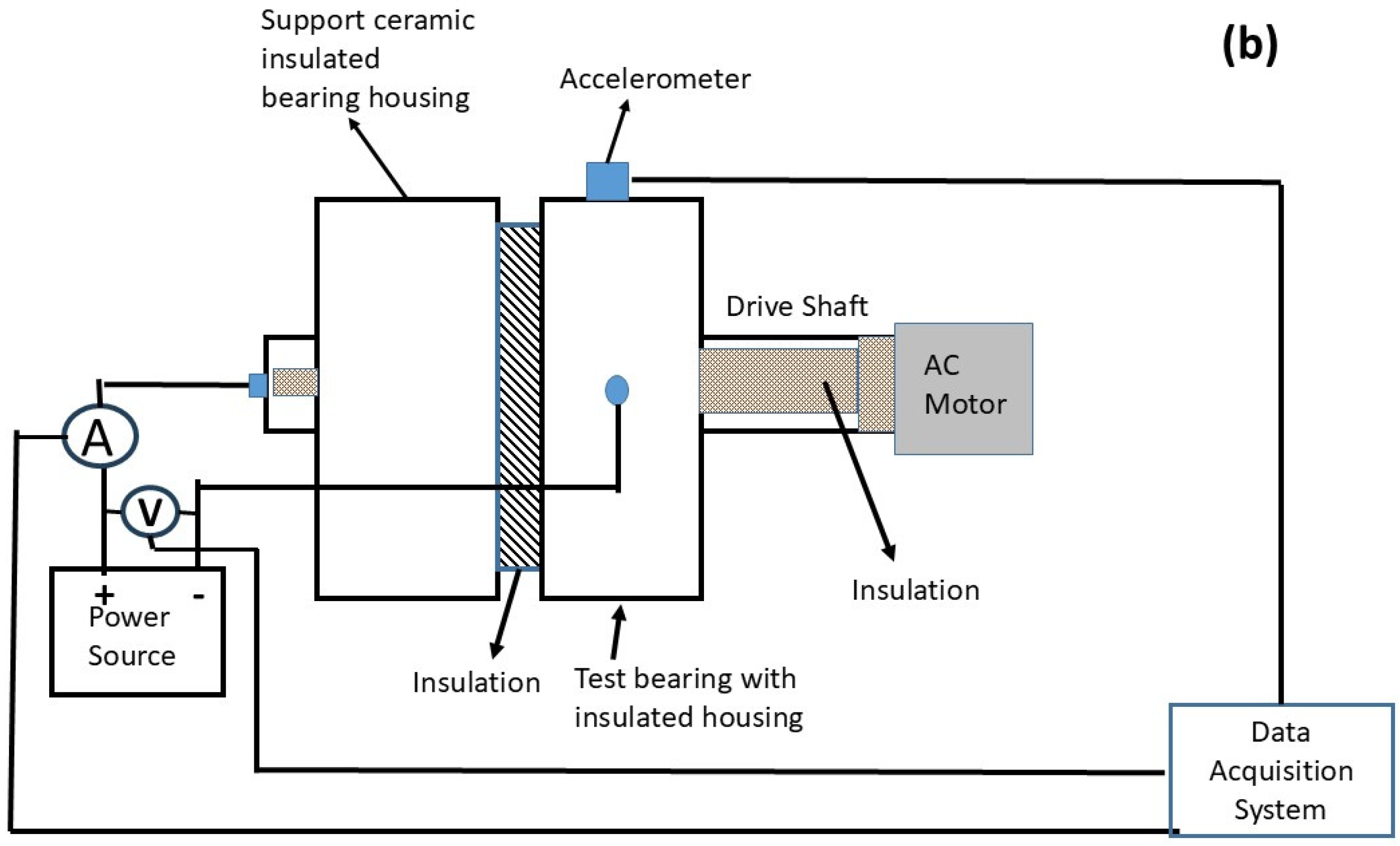
Figure 1a indicates the full-bearing test rig (Make: Magnum Engineers, Bangaluru, India) used in this work. The test rig is installed at the Tribology and Interactive Surfaces Research Laboratory (TRISUL), Amrita Vishwa Vidyapeetham, Chennai, India. Greases (5.0 ± 0.5 g) were filled into the gaps between the balls of the test bearing. To ensure a uniform grease distribution, the bearing was rotated freely before fixing it in the bearing test rig. Figure 1b shows the schematic diagram of the bearing test rig. An alternating electric current (starting at 10 A) was passed through the deep groove ball bearing mounted on a shaft. The bearing was rotated at 2000 rpm. A radial load of 496 N was applied to the bearing. An alternating current of 10 A was passed through the outer ring to the inner ring. To the best of the authors’ knowledge, bearing failures under high loads and high alternating current have not been systematically studied. Previous studies on conductive greases have indicated that a minimum 6 A is required for the formation of fluting marks [45]. However, to evaluate the grease performance under more extreme conditions, a current of 10 A was selected for the present work. The test equipment was supplied with 220 V and 50 Hz frequency. A ceramic bearing to support the shaft was used, as seen in Figure 1. The equipment used a high-class industrial grade insulator (Hylem) to prevent damage to the other parts of the equipment, except the test bearing. The radial vibrations caused due to the deterioration of the bearing raceways were picked up by an accelerometer (Make: PCB (Depew, NY, USA), Model: 333B30) fixed at the top of the bearing housing. Each set of experiments was repeated twice, and a fresh bearing was used every time. The average of the results has been presented in this work.

2.3. Surface Characterisation of the Bearing Raceways to Determine the Wear Patterns

To analyze the damages that occurred on the bearing raceways, the raceways were analyzed using an optical microscope (Make: Olympus (Tokyo, Japan), Model: BX53M) and a 3D surface profilometer (Make: Taylor Hobson (Leicester, UK), Model: Talysurf CCI). Each bearing raceway was cut to small pieces. The bearing raceway pieces with the damages on the raceways were placed under the lens of the microscope (magnification 10×) and the profilometer to capture the images.

2.4. Analysis of Greases to Determine Their Degradation

To understand the severity of wear, the iron content in the greases after the test was determined using Inductively Coupled Plasma Optical Emission spectroscopy (ICP-OES) (Make: Perkin Elmer (Waltham, MA, USA), Model: AVIO 220 Max). About 1 mg of the grease after the test was collected and used for determining the iron content using ICP-OES. The ICP-OES tests were conducted as per the ASTM D5185 method [46,47]. ASTM D5185 is used to determine 22 wear metals. About 0.3 g of grease was taken in a tube and diluted using 10 mL of white mineral oil. The mixture is mixed thoroughly to dissolve the grease. The diluted mixture is then analyzed using the ICP-OES equipment after calibrating the equipment and setting the wavelength of iron.
The degradation of the greases was further evaluated using Fourier transform infrared spectroscopy (FTIR) (Make: Bruker (Billerica, MA, USA), Model: Alpha). The process includes applying a thin layer of the test grease on the attenuated total reflectance (ATR) crystal, ensuring no entrapped bubbles. About 1 mg of fresh grease is placed on the Platinum ATR crystal as a reference sample. A spectrum is run for this fresh grease, which becomes the baseline spectrum. Similarly, an FTIR spectrum is run for the grease after the test. The degradation of the grease can be identified by the difference between the height of the peaks for the fresh grease and the used grease.

3. Results and Discussions

3.1. Performance of the Greases Under Electric Current

Figure 2 exhibits the average current, average voltage and the average vibrations generated during the tribo-test. It can be seen that the average current in case of Grease 1 is less than the average current exhibited by Grease 2. Also, the vibrations observed in Grease 1 are less than that of Grease 2. Ohm’s law indicates a significant role played by resistance in controlling the current as seen from Equation (1).
V = I R
where V is voltage (Volts, V), I is current (Ampere, A), and R is resistance (ohms, Ω).
This indicates that low resistance will allow more current to pass and vice versa. As the average current in the case of Grease 1 is less than Grease 2, it indicates that a lower current passed through the bearing in the case of Grease 1 (Figure 2a,b). Control experiments without the passage of current were also conducted. As seen from Figure 2c, the average vibrations produced during the test with Grease 2 (10 A) was highest (2369 mV ± 238) as compared with Grease 1 with 10 A (464 ± 58 mV). The vibrations produced during the test with Grease 1 (621 ± 69 mV) and Grease 2 (617 ± 10 mV) without any current were almost equal. The minor difference (0.6%) is due to the interaction pattern between the grease during the experiments. This indicates that the performance of both the greases under normal conditions remains the same; however, further information would be revealed from the surface characterizations.
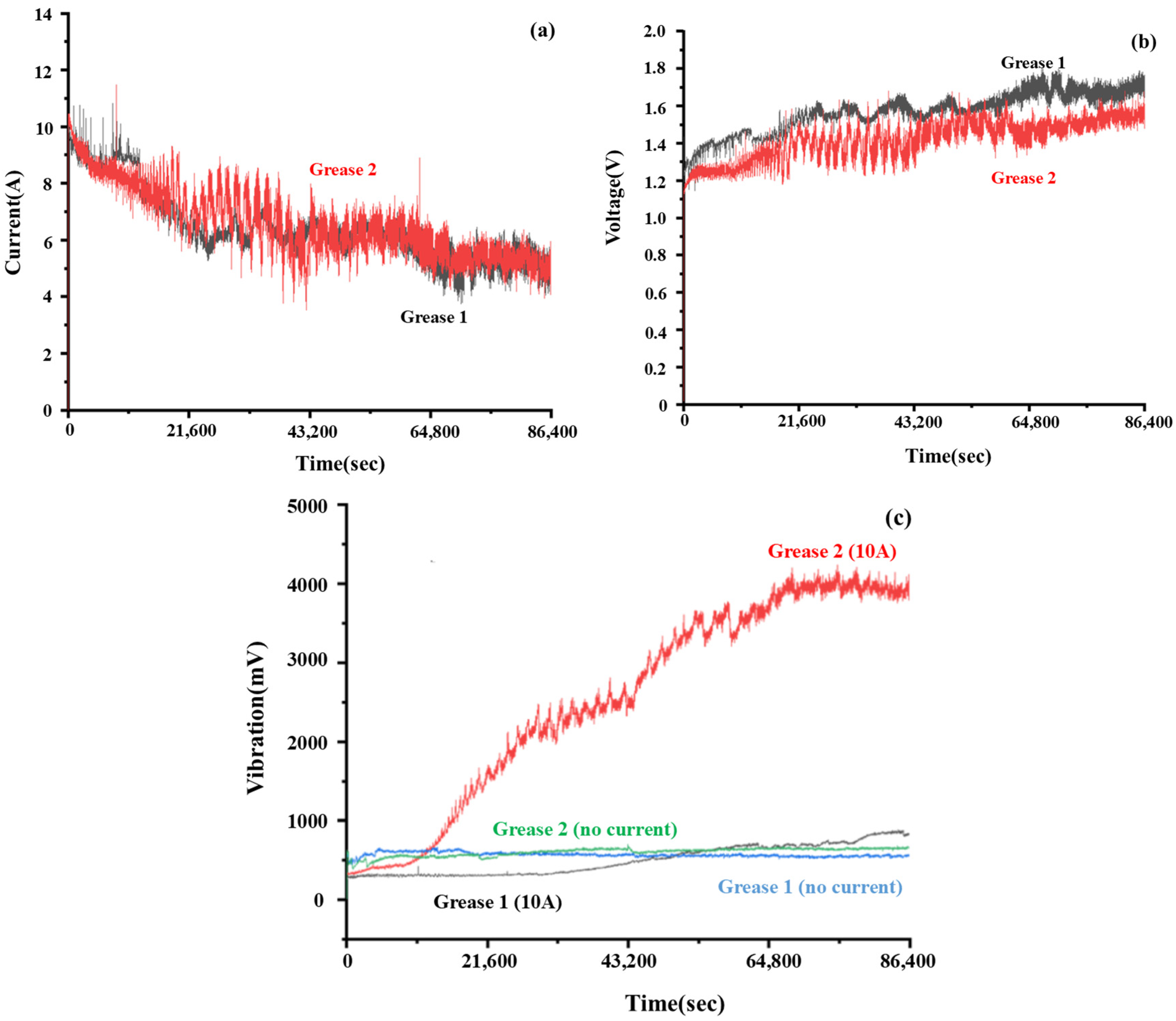
Figure 3 shows the graphs of the current, voltage, and vibrations produced during the tribo test with and without the passage of electric current. As seen from Figure 3a, the starting applied current was 10 A for both greases, but it was stabilized at 6 A–7 A; however, there were a lot of fluctuations in both the current and voltages during the full test. It is known that a grease contains base oil, thickeners, and additives. This base oil (lubricant) provides a barrier to the flow of current [34,35]. The electric current will flow when the voltage across the asperities exceeds the dielectric strength of the lubricant [29]. At the local asperity level, the applied voltage is just enough to break the dielectric strength of the lubricant, but the gap between the asperities is not uniform during the dynamic condition. Thus, fluctuations can be seen in the current graphs as well as in the voltage graphs. The voltage drop and its fluctuations are also due to the variation in gaps between the contact surfaces due to dynamic loading conditions [48]. Similarly, the voltage graph was of Grease 1 was also higher than Grease 2 (Figure 3b), which indicates that the resistance to the flow of current was greater in Grease 1 than in Grease 2. This is also an indication that the degradation of Grease 1 was less than Grease 2. These readings are further supported when the vibration graph was observed (Figure 3c). The vibration level of the bearing with Grease 1 was much less than that of Grease 2, which further strengthens the fact of less degradation of Grease 1 than Grease 2. As the voltage increases, the contact area also increases till the voltage is enough to break the breakdown strength. Beyond this voltage value, the full contact area is under the influence of that breakdown voltage, and hence, gradually, the current gets stabilized. In the graph, without the passage of current, it can be seen that both graphs almost overlap with each other without much deviation. This indicates that the performance of both the greases was similar, and hence the vibrations produced were also the same. The absence of high peaks in the graphs without the current also indicated stable film formation on the bearings. Interestingly, it is to be noted that the vibrations at the initial stage of the greases without the electric current are slightly higher than the greases under electrified conditions (Figure 3c). The high vibrations may be the result of the frictional drag, which might have been generated in the grease without the electric current. From the dimensions of the bearing, the DN ( m e a n   d i a m t e r × r p m ) value of the bearing is 92,000, and the corresponding required viscosity was found to be ISO VG 22 (considering the speed of the bearing to be 2000 rpm, mean diameter of the bearing 46 mm and operating temperature 40 °C), while the viscosity of the greases are higher than the calculated required viscosity. The passage of electric current increased the contact temperature, which would have reduced the viscosity, thus reducing the frictional drag.

3.2. Statistical Analysis of Data (t-Test)

Statistical analysis tool, t-test, was used to validate the conclusion derived from the experimental results. The t-test is used to compare the variance of the mean of two sets of data [49]. p-value was taken as 0.05. If the p-value is less than 0.05, there is strong evidence against the null-hypothesis [50]. A t-test was used to compare the data of Grease 1 and Grease 2, under 0 A and 10 A conditions. The results show that under 0 A condition, there is a negligible variation with a p-value of 0.9355 (>0.05), and under the 10 A condition, there is an obvious variation with a p-value of 0.0447 (<0.05) (Table 4). Similarly, the t-test was done between the vibration values at 0 A and 10 A for Grease 1 and Grease 2. For Grease 1, negligible variation was observed among the vibration values at 0 A and 10 A with the p-value of 0.1403 (>0.1403), whereas for Grease 2, noticeable variation was observed with the p-value of 0.0594 (~0.05) (Table 4). The experimental results indicated that the vibration at 10 A for Grease 2 (2200.39) was greater than that of Grease 1 (422.92). It can also be seen that the value of vibration for Grease 1 has negligible variation with an increase in current, whereas for Grease 2, the vibration increased with an increase in current (Table 4). This indicated that Grease 1 performed better than Grease 2.

3.3. Investigating the Grease Degradation During the Tribo Test

Figure 3 shows that the low resistance to the current is due to the degradation of the lubricant in the bearing. The discoloration of the grease confirmed the degradation of the lubricant. It was observed that both greases became discolored in the presence of the electric current, indicating degradation of both greases (Figure 4). However, the extent of degradation of Grease 2 appears to be greater than that of Grease 1, which is later confirmed using FTIR analysis. The degradation of the greases happens due to the formation of free radicals. The passage of electric currents through the bearing surface and the severe slip of the balls results in the exposure of new surfaces. These surfaces act as activated sites for chemical reaction, which catalyze accelerated free radical formation in the lubricant [51]. As the lubricant degrades, there is a chance of localized heating due to the lubricant film breakages. The localized heating further accelerates the formation of free radicals [52,53]. As the radicals are formed, they interact with other lubricant molecules and degrade the lubricant. Additionally, the combination of free electrons and grease degradation leads to the formation of hydrogen, which penetrates the bearing steel, leading to the failure of the bearing steel surfaces due to hydrogen embrittlement [48]. Thus, the degradation of the greases leads to surface deterioration, which eventually leads to high slip on the raceways of the bearings, resulting in high vibrations as detected by the vibration sensor. Sanchez et al. [23] also indicated that the presence of electric current deteriorates the performance of the bearing due to the formation of micro-pitting and spalling damages.
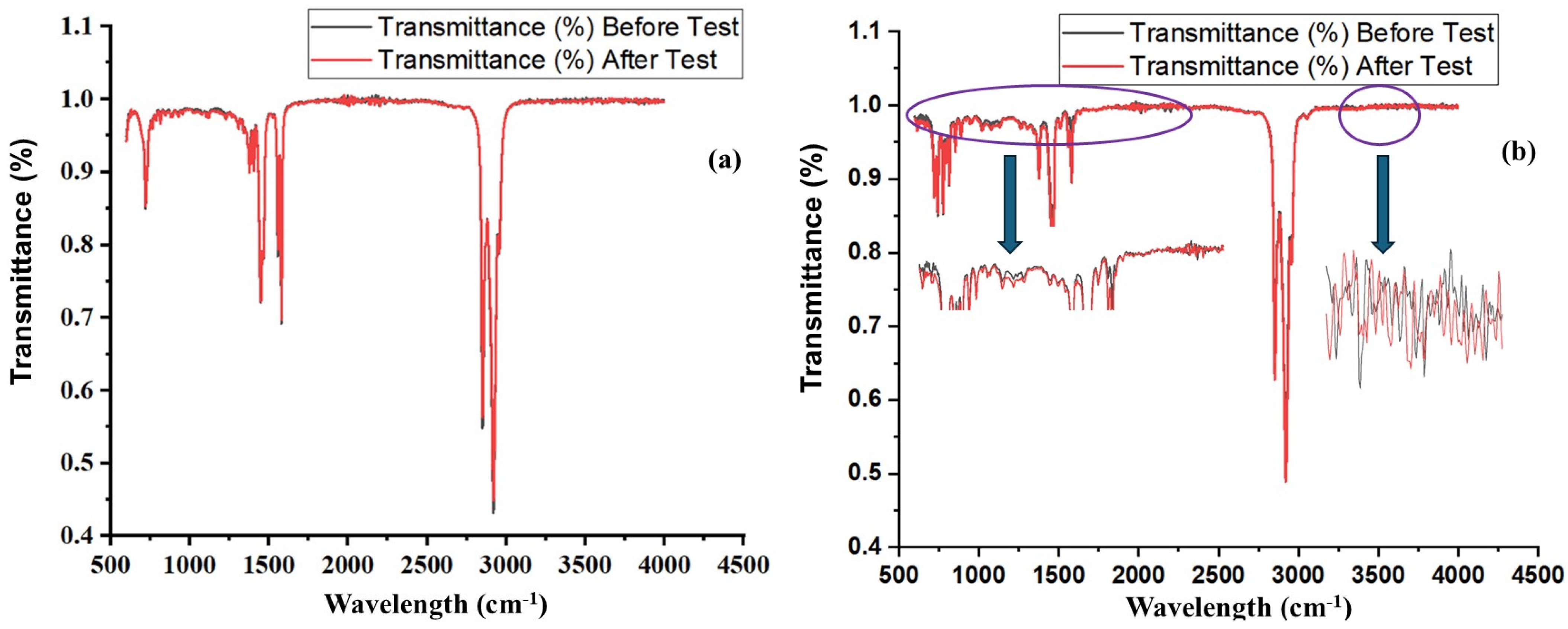
FTIR was used to further analyze the degradation of the greases during the tribo test under the influence of the electric current as well as without the electric current (Figure 5 and Figure 6). The FTIR spectrum of Grease 1 indicated the presence of alkane and alkene bonds with peaks around the range of 2500–3000 cm−1 (2848 cm−1 and 2919 cm−1), which confirms the presence of PAO [54]. The peaks around the range of 1700 cm−1 (1577 cm−1 and 1448 cm−1) correspond to the C=O stretching of ester [55]. The peak around the range of 1100 cm−1 (721 cm−1) corresponds to the C-O stretching of ester [55]. The FTIR spectrum of the Grease 2 exhibited the presence of alkane and alkene bonds with peaks around the range of 2500–3000 cm−1 (2921 cm−1 and 2851 cm−1), which confirms the presence of PAO. The peaks around the range of 1700 cm−1 (1580 cm−1 and 1378 cm−1) correspond to the C=O stretching of ester [55]. The peak around the range of 1100 cm−1 (776 cm−1) corresponds to C-O stretching of the ester [55]. Comparing the FTIR curves of the greases before and after the test, no change in the graphs in Grease 1 can be seen (Figure 5a and Figure 6a). In Grease 2, grease degradation can easily be identified with the significant changes in the graph curves before and after the test (Figure 5b and Figure 6b). Though the vibrations recorded during the tribo test without the presence of electric current was almost same in both the greases, a slight degradation of Grease 2 was observed from FTIR results (Figure 5). Additionally, for the tests conducted under electric conditions, Grease 2 was found to have degraded more while no significant degradation was observed for Grease 1 (Figure 6). These results are in line with the poor performance of Grease 2 during the tribo tests, as it indicated extensive surface damage after the test, high vibrations, and the presence of a high amount of iron (Fe) content after the test, particularly in electric conditions.
As reported by researchers, the degradation of the greases would also generate hydrogen free radicals, which would react with the molecules of the grease, thus producing more free radicals [48]. It has already been reported that the formation of free electrons due to lubricant degradation is the key factor for the formation of WEAs. The presence of an electric current would result in the generation of fresh surfaces and active sites for hydrogen penetration. This hydrogen produced due to lubricant degradation would penetrate the bearing steel, leading to hydrogen-induced WEAs [48]. During running conditions in the presence of electric currents, the penetration of hydrogen results in alteration of the microstructure, which results in accumulation of various carbides, resulting in an increase in hardness in WEAs.

3.4. Exploring the Microstructural and Surface Damages of the Bearings During Tribo Test

To understand the microstructural and surface damages, the bearing raceways were analyzed using an optical microscope. Figure 7 indicates the surface damage of the bearing raceways, which were running without the presence of an electric current. Micro-pittings and ridge formation were common on the raceways while using both types of grease.
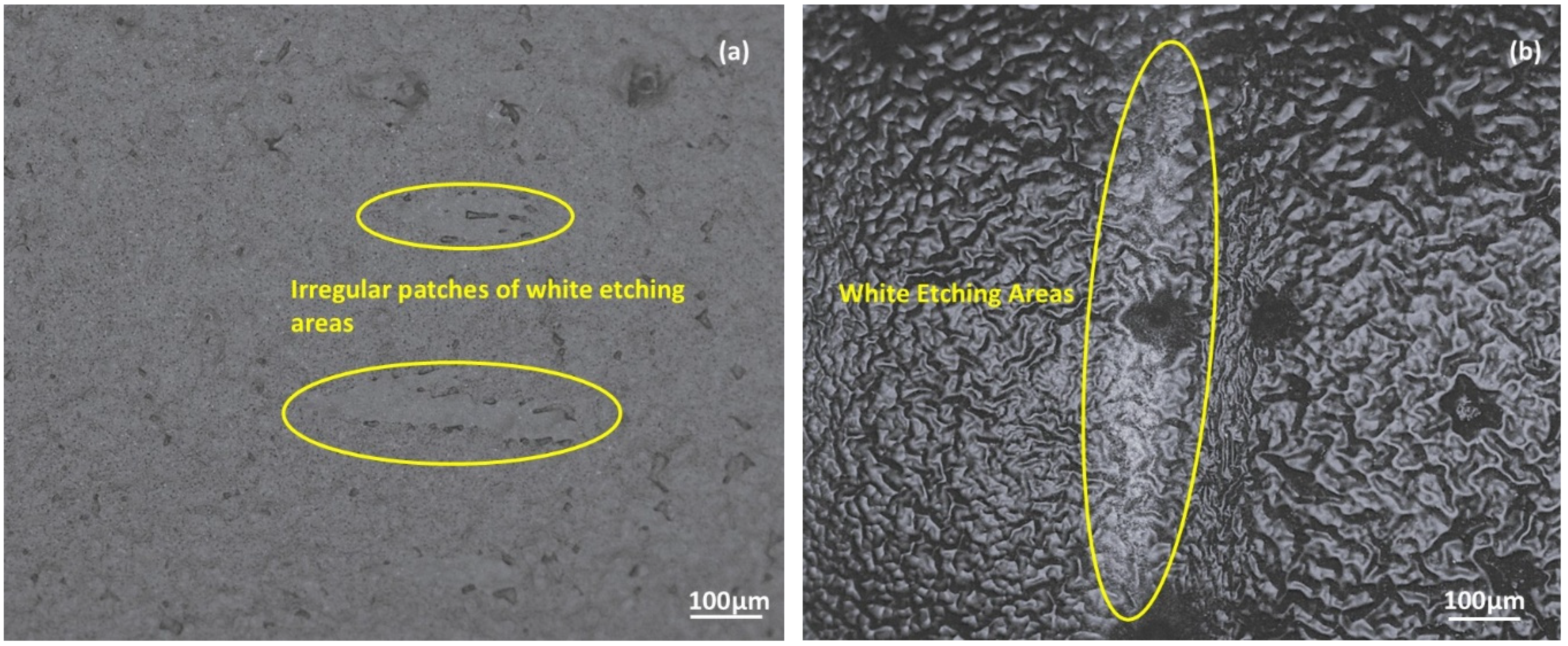
On further exploration of the damages on the bearing raceways by analyzing the microstructure of the bearing raceways (Figure 8), irregular white etching areas (WEA) were observed on the surface of the bearing raceways under electrified conditions. Bai et al. [48] reported that these irregular WEAs result from the randomized movement of carbides, overloads, or local heating. These WEAs are microstructural alterations of steel that appear white under an optical microscope after etching. As seen in Figure 8, a difference in the microstructure was observed between Grease 1 and Grease 2 under the same magnification. The electric current passing through the bearings resulted in a severe change in the microstructure. The microstructure of the bearing with Grease 2 was much deteriorated as compared to Grease 1. The formation of WEAs was further confirmed by measuring the WEAs’ hardness and the surrounding areas. A fresh bearing race way exhibited an average Rockwell hardness of 80.1 ± 1.25 HRC, while with Grease 1 the hardness of the bearing raceway along the area of damage was 82.6 ± 0.5 HRC, and with Grease 2, the hardness of the bearing raceway along the area of damage was 83.8 ± 0.2 HRC. Thus, when compared with the hardness of a fresh bearing, an increase of 3.02% with Grease 1 and 4.4% hardness was observed in the damaged areas. The increase in hardness is due to the formation of carbides as a result of microstructure alteration [56]. Similar to the works of Bai et al. [48], no cracks were observed within the WEAs. However, WEAs initiate crack formation, which would develop after a longer test duration.
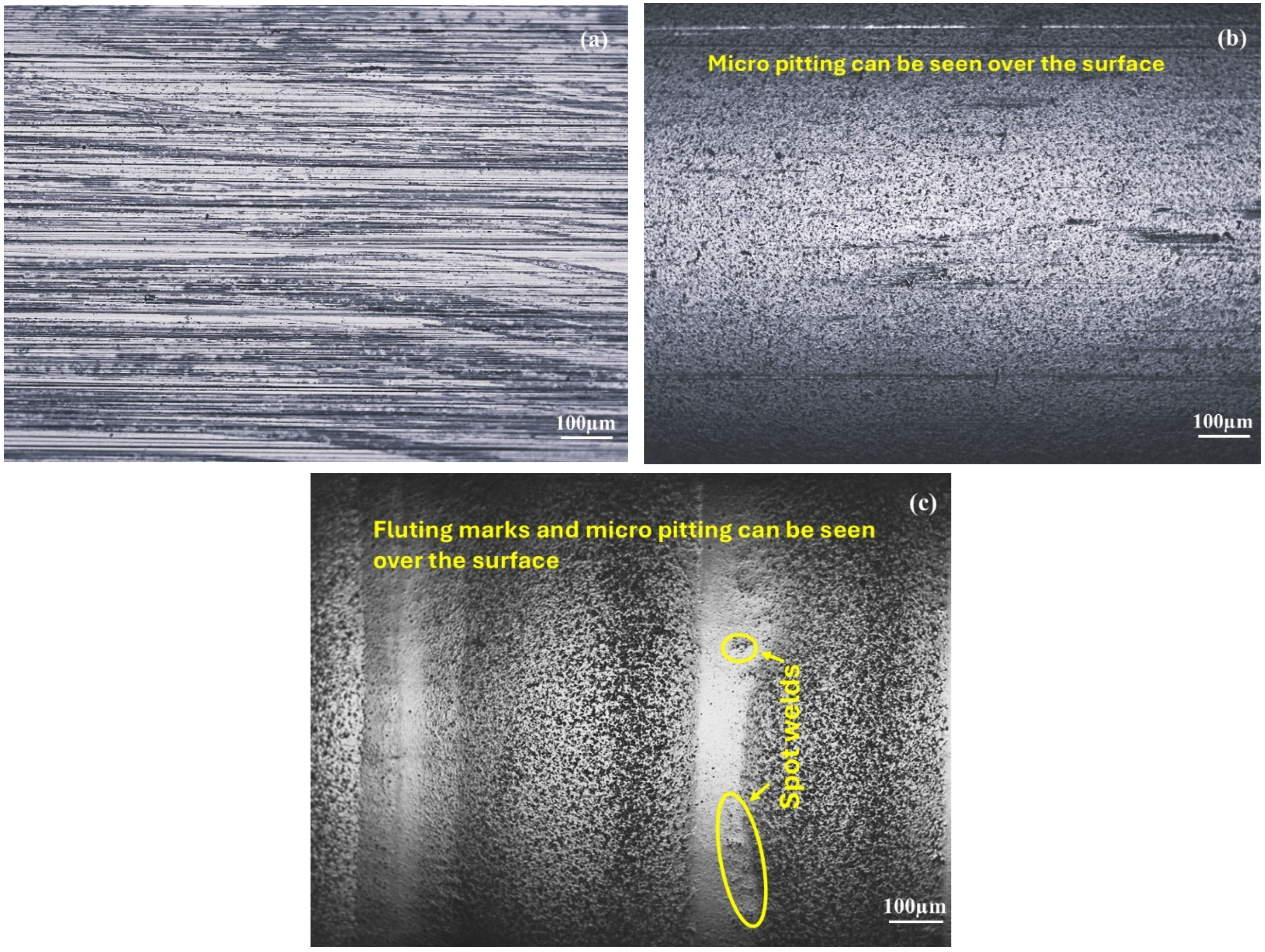
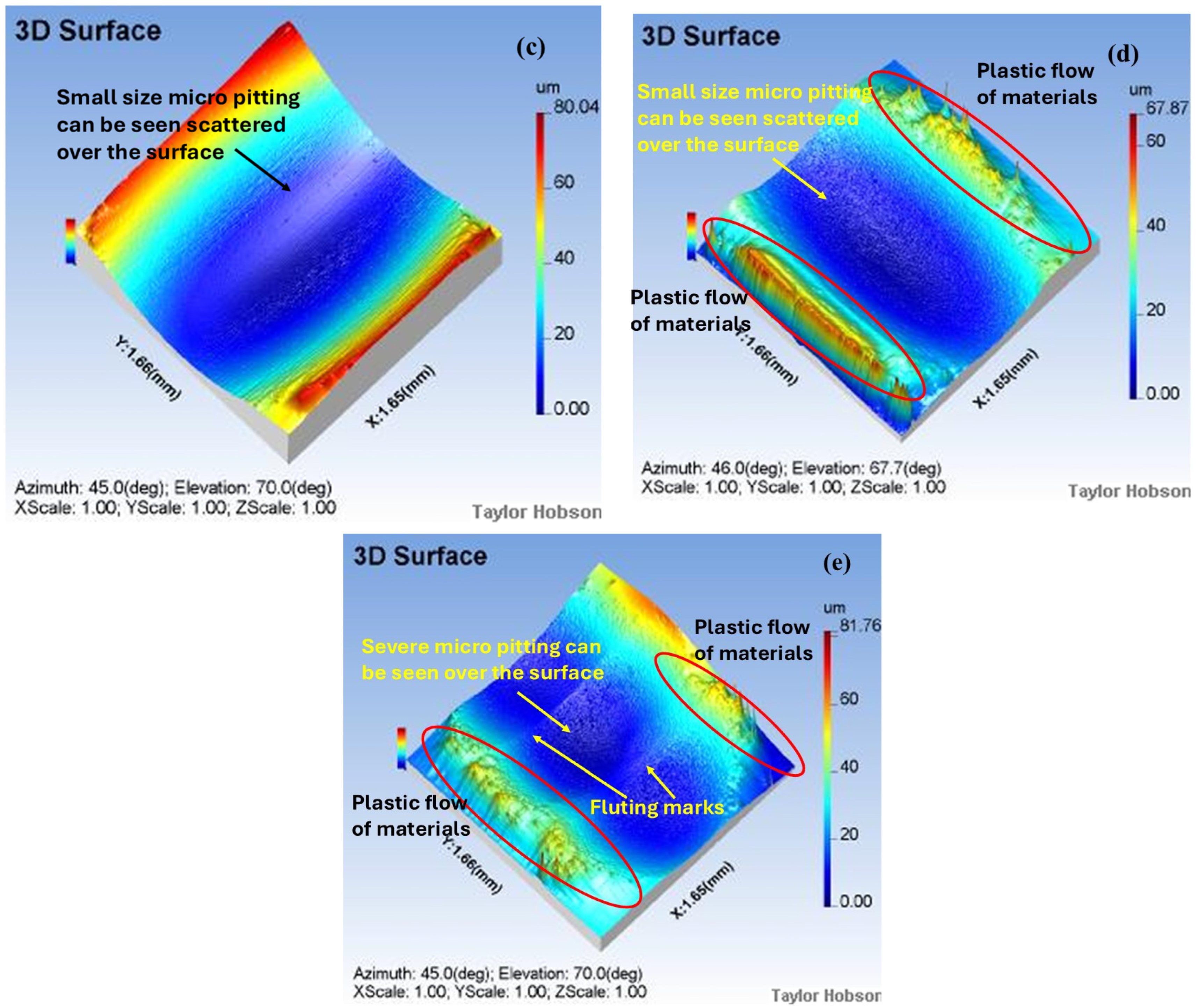
Figure 9 exhibits the micro-pitting formation, fluting marks formation, and spot welds on the bearing raceways. Figure 9a exhibits the fresh surface of the bearing raceways before the test. The three-dimensional images from the profilometer indicate a few micro-pittings on the bearing raceways (Figure 9b,c), which were tested without the current. As indicated earlier, the degradation of the lubricant due to the passage of current would result in localized heating [56]; hence, excessive plastic deformation can be seen along the sides of the raceways (Figure 10). The localized spot welds shear under sliding, and the debris may play a role in producing the scratch marks on the bearing surfaces (three-body abrasion). The optical microscope images of the bearing raceways exhibited substantial damage with Grease 2 as compared to Grease 1, making a strong point of a stable lubricating film by Grease 1.

3.5. Role of Oil, Surface Asperities, Oil Viscosity, and Wear Debris During the Tribo Test

The iron (Fe) content in the grease samples was also evaluated using an ICP-OES (Table 5). The Fe content in the greases taken from the experiments running without current was almost similar in both greases. This is in line with the observations seen in earlier sections, where the surface damages as well as the vibrations in the case of no current passage were also almost the same. However, in the experiments with the passage of current, higher Fe content in Grease 2 was observed. This indicated that the surfaces of the bearing with Grease 2 were damaged significantly as compared to Grease 1 when an electric current was passed. The damages would have resulted in the misalignment of the balls along the raceways, leading to improper rolling, thus resulting in high vibrations during the test. The Fe content results also indicated that the greases performed better under non-electric conditions.
Tajedini et. al. [57] reported an increase in current density due to the presence of sharp asperities or the presence of thinner lubricating films, increasing localized temperature. The present results are also similar to their reported results of melted portions of the contacting surfaces. Additionally, the presence of iron particles in the grease indicates the formation of solidified wear particles that were detached from the surfaces of the bearings. These solid particles further contribute to accelerating the wear during the process. This is in line with the Fe content results shown in Table 4, where the Fe content in Grease 1 was less than Grease 2. Thus, the presence of high Fe content in Grease 2 accelerated the surface damage. Lubricant film thickness also affects the intensity and the electric discharges [57]. Thus, the base oil viscosity plays an important role in controlling the damage to the bearings. As Grease 2 has a lower base oil viscosity (32–35 cSt), it exhibited less insulation compared to Grease 1, which had higher viscosity (46–54 cSt). The higher viscosity of Grease 1 was responsible for generating a better protective barrier, thus reducing the occurrence of electric discharge. Thus, it can be seen that the viscosity of the base oil of the greases helps in controlling the wear occurring in the bearing and extending the bearing life. The contact areas experiencing thinner lubricating films generate more heat due to intense asperity contacts and thus suffer more damage due to larger electric discharges. Contrary to that, the thicker lubricating film exhibits better insulation and a good film stability, thus experiencing fewer electric discharges. This phenomenon of the presence of thin and thick lubricating films between the tribo-pairs results in non-uniform wear patterns with small pits in thick lubricating films and large pits in thin lubricating films. Bai et al. [48] also reported that the energy accumulation and electric discharge, third body contact of the asperities, and the pitting formation are the primary modes of failures of the surfaces under electrified conditions. The presence of wear debris, air bubbles, and contact inhomogeneities also favors the current flow through the asperities of the two mating pairs. The observed increase in voltage here indicates a decrease in resistance, which may be due to the formation of micro bubbles [58] and an increase in surface temperature. The decrease in film thickness ultimately exposes more areas of failures, resulting in excessive metal–metal contact and lubricant degradation.

4. Conclusions

This work investigated the degradation of the bearing surfaces in the presence of commercial greases at high current, load, and speed using a novel full bearing test rig. The key conclusions derived from the work are as follows:
  • Choice of lubricant is important to protect the bearings from failure due to the passage of electric current. In this work, the lithium 12-hydroxy stearate grease containing ester and PAO performed better than the other lithium grease containing ester, PAO, and aromatic oils. However, the physicochemical properties of the lubricant also play an important role, as seen in the next point.
  • In non-electrified conditions, the tribological performance of both the greases was found to be similar. The bearing surface damages and the vibrations produced in both greases were almost similar in the non-electrified condition.
  • Results indicated that during the tribo test, the average current maintained using Grease 1 (5.8 ± 0.81 A) was less than Grease 2 (6.3 ± 0.42 A), while the average voltage in Grease 1 (1.5 ± 0.02) was more than Grease 2 (1.4 ± 0.04 V). The vibrations of the bearing with Grease 1 (464 ± 58.39 mV) were 80% less than the vibrations recorded during the test with Grease 2 (2369 ± 238 mV), indicating a stable lubricating film of Grease 1 during the test.
  • The viscosity of the lubricant is an important parameter as it is related to the film thickness formation between the mating pair, even in dynamic conditions. In the present work, the performance of the lubricant with higher viscosity (46–54 cSt) was found to be better with low vibrations and lesser surface damage as compared to the lubricant with 32–35 cSt viscosity.
  • FTIR indicated that Grease 1 did not degrade like Grease 2, and hence Grease 1 worked effectively in preventing failures of the bearings under both electric and non-electrified conditions. Additionally, the discoloration of Grease 2 indicated that Grease 2 degraded with the passage of electric current.
  • WEAs, micro-pitting, weld spots, plastic deformations, and flutings were failure mechanisms as observed from the microscopic images.
  • Though the iron particles generated in non-electrified conditions were almost similar in both the greases, but in electrified conditions, higher iron particles as wear debris were observed in Grease 2, which exhibited high vibration during the test and major surface damage as compared to Grease 1.
  • Statistical analysis indicates no significant variant in non-electrified conditions while significant variance can be observed in electrified conditions.
Though the present work has exhibited the failures of the bearings under a constant load, rpm, and current, future work has been planned to investigate the wear of the bearings under various currents, loads, and rpms. Additionally, other types of greases will also be used to determine the suitability of the greases in future work. The present work will be highly beneficial in understanding the tribological properties of the lithium-based greases containing esters, thus helping the lubricant manufacturers to develop high performance lubricants for electrified conditions.

Author Contributions

Conceptualization, S.B.; methodology, S.B.; software, S.B. and V.P.; validation, S.B., V.P., G.H. and M.Y.; formal analysis, S.B. and S.M.; investigation, S.B.,V.P., S.J. and M.Y.; resources, S.B., M.Y. and S.J.; data curation, G.H., M.Y. and S.J.; writing—S.B., M.Y., A.K.S., V.P. and S.J.; writing—review and editing, V.P., S.M., S.B. and A.K.S.; visualization, S.B., V.P. and A.K.S.; supervision, S.B.; project administration, S.B. and S.M. All authors have read and agreed to the published version of the manuscript.

Funding

This research received no external funding.

Institutional Review Board Statement

Not applicable.

Informed Consent Statement

Not applicable.

Data Availability Statement

Data can be made available from the corresponding author upon reasonable request.

Conflicts of Interest

Author Shail Mavani was employed by the company Mosil Lubricants Private Limited. The remaining authors declare that the research was conducted in the absence of any commercial or financial relationships that could be construed as a potential conflict of interest.

References

  1. Morales Udaeta, M.E.; Chaud, C.A.; Gimenes, A.L.V.; Galvao, L.C.R. Electric Vehicles Analysis inside Electric Mobility Looking for Energy Efficient and Sustainable Metropolis. Open J. Energy Eff. 2015, 4, 1–14. [Google Scholar] [CrossRef]
  2. Mei, J.; Zuo, Y.; Lee, C.H.T.; Kirtley, J. Modeling and Optimizing Method for Axial Flux Induction Motor of Electric Vehicles. IEEE Trans. Veh. Technol. 2020, 69, 5. [Google Scholar] [CrossRef]
  3. Lu, J.D.; Hu, Y.H.; Chen, G.P.; Wang, Z.; Liu, J.L. Mutual Calibration of Multiple Current Sensors with Accuracy Uncertainties in IPMSM Drives for Electric Vehicles. IEEE Trans. Ind. Electron. 2020, 67, 69–79. [Google Scholar] [CrossRef]
  4. Patel, N.R.; Shah, V.A.; Lokhande, M.M. A Novel Approach to the Design and Development of 12/15 Radial Field C-Core Switched Reluctance Motor for Implementation in Electric Vehicle Application. IEEE Trans. Veh. Technol. 2018, 67, 8031–8040. [Google Scholar] [CrossRef]
  5. Yildirim, M.; Ayaz, M. A Survey on Comparison of Electric Motor Types and Drives Used for Electric Vehicles. Int. J. Adv. Sci. Technol. 2015, 84, 23–32. [Google Scholar] [CrossRef]
  6. Wang, X.; Lu, S.; Chen, K.; Wang, Q.; Zhang, S. Bearing Fault Diagnosis of Switched Reluctance Motor in Electric Vehicle Powertrain via Multisensor Data Fusion. IEEE Trans. Ind. Inform. 2022, 18, 2452–2464. [Google Scholar] [CrossRef]
  7. Hamachi, T.; Tohei, T.; Hayashi, Y.; Imanishi, M.; Usami, S.; Mori, Y.; Sakai, A. Comprehensive Analysis of Current Leakage at Individual Screw and Mixed Threading Dislocations in Freestanding GaN Substrates. Sci. Rep. 2023, 13, 2436. [Google Scholar] [CrossRef]
  8. He, F.; Xie, G.; Luo, J. Electrical Bearing Failures in Electric Vehicles. Friction 2020, 8, 4–28. [Google Scholar] [CrossRef]
  9. Liu, W. The Prevalent Motor Bearing Premature Failures Due to the High Frequency Electric Current Passage. Eng. Fail. Anal. 2014, 45, 118–127. [Google Scholar] [CrossRef]
  10. Morris, N.; Bleger, A.; Leighton, M. Automotive E-Motor Bearing Electrical Discharge Phenomena: An Experimental and Numerical Investigation. Tribol. Int. 2023, 188, 108524. [Google Scholar] [CrossRef]
  11. Lee, H.Y.; Ahn, S.H.; Im, H.T. A Research on Stray-Current Corrosion Mechanism of High Voltage Cable Connector on Electrification Vehicles. Corros. Sci. Technol. 2019, 18, 117–120. [Google Scholar] [CrossRef]
  12. Lou, Z.; Song, C.; Ren, Y.; Pang, X.; Lu, H.; Du, S.; Zhang, Y. Formation of Corrugated Damage on Bearing Race under Different AC Shaft Voltages. Materials 2024, 17, 859. [Google Scholar] [CrossRef]
  13. Chiou, Y.C.; Lee, R.T.; Lin, C.M. Formation Criterion and Mechanism of Electrical Pitting on the Lubricated Surface under AC Electric Field. Wear 1999, 236, 62–72. [Google Scholar] [CrossRef]
  14. Janik, J.R.; Saha, S.; Evans, R.L. Exploring the Boundaries of Electrically Induced Bearing Damage in Grease-Lubricated Rolling Contacts. Lubricants 2024, 12, 268. [Google Scholar] [CrossRef]
  15. De Gaetano, D.; Zhu, W.; Sun, X.; Chen, X.; Griffo, A.; Jewell, G.W. Experimental Ball Bearing Impedance Analysis Under Different Speed and Electrical Conditions. IEEE Trans. Dielectr. Electr. Insul. 2023, 30, 1312–1321. [Google Scholar] [CrossRef]
  16. Lin, C.-L.; Meehan, P.A. Morphological and Elemental Analysis of Wear Debris Naturally Formed in Grease Lubricated Railway Axle Bearings. Wear 2021, 484–485, 203994. [Google Scholar] [CrossRef]
  17. Desnica, E.; Ašonja, A.; Radovanović, L.; Palinkaš, I.; Kiss, I. Selection, Dimensioning and Maintenance of Roller Bearings. In 31st International Conference on Organization and Technology of Maintenance (OTO 2022). OTO 2022; Blažević, D., Ademović, N., Barić, T., Cumin, J., Desnica, E., Eds.; Lecture Notes in Networks and Systems; Springer: Cham, Switzerland, 2023; Volume 592. [Google Scholar] [CrossRef]
  18. Tawfiq, K.B.; Güleç, M.; Sergeant, P. Bearing Current and Shaft Voltage in Electrical Machines: A Comprehensive Research Review. Machines 2023, 11, 550. [Google Scholar] [CrossRef]
  19. Graf, S.; Capan, R.; Koch, O.; Sauer, B. Electrically Induced Damage of Rolling Bearings Due to Parasitic Converter Currents in Electrical Drive Trains. In Commercial Vehicle Technology 2022; Berns, K., Dressler, K., Kalmar, R., Stephan, N., Teutsch, R., Thul, M., Eds.; Springer Vieweg: Wiesbaden, Germany, 2023; pp. 199–209. [Google Scholar] [CrossRef]
  20. Mehnert, M.; Faber, J.; Hossain, M.; Chester, S.A.; Steinmann, P. Experimental and Numerical Investigations of the Electro-Mechanical Response of Particle Filled Elastomers—Part II: Continuum Modeling Approach. Eur. J. Mech. A-Solids 2022, 96, 104661. [Google Scholar] [CrossRef]
  21. Xie, Z.; Xu, X. Experimental Study on Electro-Mechanical Response Characteristics of PZT5H Piezoelectric Ceramics Under Impact Loading. J. Asian Ceram. Soc. 2021, 9, 158–164. [Google Scholar] [CrossRef]
  22. Li, J.; Gao, B.; Wang, X.; Li, F.; Jing, G.; Bai, P.; Tian, Y. Influence and Mechanism of Ablation Pits on the Electrical Contact Stability of Conductive Slip Rings. J. Tsinghua Univ. Sci. Technol. 2025, 60, 41. [Google Scholar] [CrossRef]
  23. Sanchez, L.J.; Hager, C.H.; Evans, R.D. Rolling Element Bearing Damage in the Presence of Applied Electric Current. Tribol. Trans. 2024, 67, 602–613. [Google Scholar] [CrossRef]
  24. Ma, J.; Xue, Y.; Han, Q.; Li, X.; Yu, C. Motor Bearing Damage Induced by Bearing Current: A Review. Machines 2022, 10, 1167. [Google Scholar] [CrossRef]
  25. Farfan-Cabrera, L.I. Tribology of Electric Vehicles: A Review of Critical Components, Current State and Future Improvement Trends. Tribol. Int. 2019, 138, 473–486. [Google Scholar] [CrossRef]
  26. Lugt, P.M.; van Zoelen, M.T.; Vieillard, C.; Berens, F.; Gruell, R.; Preisinger, G.; Meaney, P. Grease Performance in Ball and Roller Bearings for All-Steel and Hybrid Bearings. Tribol. Trans. 2022, 65, 1–13. [Google Scholar] [CrossRef]
  27. Randall, R.B. Vibration Based Condition Monitoring: Industrial, Automotive and Aerospace Applications, 2nd ed.; Wiley: Hoboken, NJ, USA, 2021. [Google Scholar]
  28. Joe, S.B.; Gomathi, T.; Marshiana, D.; Krishnamoorthy, N.R. Effects of Joule Heating on the Temperature-Voltage Relationship in Copper. In Proceedings of the 2021 6th International Conference on Inventive Computation Technologies (ICICT), Coimbatore, India, 20–22 January 2021; pp. 400–403. [Google Scholar] [CrossRef]
  29. Balakrishna, G.V.; Gnanamoorthy, R. Current–Voltage–Friction Characteristics of Grease in Electromechanically Loaded Sliding Contacts. J. Tribol. 2023, 145, 041701. [Google Scholar] [CrossRef]
  30. Xu, F.; Ding, N.; Li, N.; Liu, L.; Hou, N.; Xu, N.; Guo, W.; Tian, L.; Xu, H.; Wu, C.-M.L.; et al. A Review of Bearing Failure Modes, Mechanisms and Causes. Eng. Fail. Anal. 2023, 147, 107518. [Google Scholar] [CrossRef]
  31. Evenhuis, C.J. Joule Heating Effects and the Experimental Determination of Temperature during CE. Electrophoresis 2009, 30, 897–909. [Google Scholar] [CrossRef] [PubMed]
  32. Li, Z.; Guo, F.; Jing, Z.; Li, B.; Zhang, L.; Wang, X. Study on Electric Erosion in Grease Lubrication Using Optical Interference Method. Tribol. Int. 2024, 195, 109596. [Google Scholar] [CrossRef]
  33. Li, Z.; Guo, F.; Jing, Z.; Li, B.; Zhang, L.; Wang, X. Study on Grease Lubrication and Electric Erosion Characteristics in AC Electric Fields. Lubricants 2024, 12, 79. [Google Scholar] [CrossRef]
  34. Turnbull, R.; Rahmani, R.; Paul, S.; Rahnejat, H. Electrotribodynamics of Ball Bearings in Electrical Machines. Tribol. Int. 2023, 188, 108817. [Google Scholar] [CrossRef]
  35. Joshi, A. Electrical Characterisations of Bearings. Ph.D. Thesis, Chalmers University of Technology, Gothenburg, Sweden, 2019; pp. 1–90. Available online: https://research.chalmers.se/en/publication/508930 (accessed on 10 May 2025).
  36. Janik, J.R.; Saha, S.; Jackson, R.L.; Mills, G. Rheological and Electro-Pitting Performance of Electric Vehicle Motor Greases with Various Nanoparticle Greases. J. Tribol. 2024, 147, 051110. [Google Scholar] [CrossRef]
  37. Kanazawa, Y.; Sayles, R.S.; Kadiric, A. Film Formation and Friction in Grease Lubricated Rolling-Sliding Non-Conformal Contacts. Tribol. Int. 2017, 109, 505–518. [Google Scholar] [CrossRef]
  38. Du, Z.; He, Q.; Wan, H.; Zhang, L.; Xu, Z.; Xu, Y.; Li, G. TiO2 and CeO2 Nanoparticles as Lithium Complex Grease Additives for Enhanced Lubricity. Ind. Lubr. Tribol. 2024, 76, 70–80. [Google Scholar] [CrossRef]
  39. Sánchez, R.; Franco, J.M.; Delgado, M.A.; Valencia, C.; Gallegos, C. Development of New Green Lubricating Grease Formulations Based on Cellulosic Derivatives and Castor Oil. Green Chem. 2009, 11, 931–939. [Google Scholar] [CrossRef]
  40. Abu Saad, S.; Elmahjubi, A. Nanotechnology: Concepts, Importance and the Current State of Scientific Research. In Proceedings of the Conference on Engineering Sciences and Technology (CEST) 2018, Garaboulli, Libya, 25–27 September 2018; Volume 4, pp. 555–561. [Google Scholar] [CrossRef]
  41. Chang, H.; Lan, C.W.; Chen, C.H.; Kao, M.J.; Guo, J.B. Anti-Wear and Friction Properties of Nanoparticles as Additives in the Lithium Grease. Int. J. Precis. Eng. Manuf. 2014, 15, 2059–2063. [Google Scholar] [CrossRef]
  42. Deepika. Nanotechnology Implications for High Performance Lubricants. SN Appl. Sci. 2020, 2, 1128. [Google Scholar] [CrossRef]
  43. Ono, A. Revision of the Standard Method (JIS G 1253) for Spark Discharge Atomic Emission Spectrometry of Iron and Steel. Tetsu-to-Hagané. 1995, 81, 869–875. [Google Scholar] [CrossRef]
  44. JIS G 1253-13; Iron and Steel—Method for Spark Discharge Atomic Emission Spectrometric Analysis. Japanese Standard Association: Tokyo, Japan, 1995.
  45. Suzumura, J. Prevention of Electrical Pitting on Rolling Bearings by Electrically Conductive Grease. Q. Rep. RTRI 2016, 57, 42–47. [Google Scholar] [CrossRef] [PubMed]
  46. ASTM D5185; Standard Test Method for Multielement Determination of Used and Unused Lubricating Oils and Base Oils by Inductively Coupled Plasma Atomic Emission Spectrometry (ICP-AES). ASTM: West Conshohocken, PA, USA, 2018.
  47. Calabokis, O.P.; Nuñez de la Rosa, Y.; Borges, P.C.; Cousseau, T. The Corrosive Effects of Aftermarket Oil Additives on High-Leaded Tin Bronze Alloy. Materials 2024, 17, 1326. [Google Scholar] [CrossRef]
  48. Bai, B.; Davis, L.; Ramkumar, P. Electrical current effects on white etching areas formation in bearing steel under dynamic loading. Wear 2025, 570, 205977. [Google Scholar] [CrossRef]
  49. Kim, T.K. T test as a parametric statistic. Korean J. Anesthesiol. 2015, 68, 540–546. [Google Scholar] [CrossRef] [PubMed]
  50. Shreffler, J.; Huecker, M.R. Hypothesis Testing, P Values, Confidence Intervals, and Significance. In StatPearls [Internet]; StatPearls Publishing: Treasure Island, FL, USA, 2025; [Updated 13 March 2023]. Available online: https://www.ncbi.nlm.nih.gov/books/NBK557421/ (accessed on 10 May 2025).
  51. Mikami, H.; Kawamura, T. Influence of Electrical Current on Bearing Flaking Life; SAE Technical Paper 2007-01-0113; SAE International: Warrendale, PA, USA, 2007. [Google Scholar] [CrossRef]
  52. Wu, N.; Zong, Z.M.; Fei, Y.W.; Ma, J. Studies on Thermal Oxidation Stability of Aviation Lubricating Oils. In Proceedings of the 2017 International Conference on Mechanical, Material and Aerospace Engineering (2MAE 2017), Beijing, China, 12–14 May 2017; p. 02002. [Google Scholar] [CrossRef]
  53. Zhang, X.; Huang, X.; Li, J.; Tang, Z.; Wang, J. Thermal oxidation of aviation lubricating oil: Mechanism, influencing factors, evaluation methods, and antioxidants. Asia-Pac. J. Chem. Eng. 2024, 19, e3114. [Google Scholar] [CrossRef]
  54. Fei, Y.-W.; Ma, S.-J.R.J.; Guo, F. Study on Thermal Oxidation and Viscosity Degradation for Synthetic Aviation Lubricant Fluids. IOP Conf. Ser. Mater. Sci. Eng. 2020, 729, 012072. [Google Scholar] [CrossRef]
  55. Shekhawat, D.; Jain, A.; Vashishtha, N.; Singh, A.P.; Kumar, R. Tribological Performance Comparison of Lubricating Greases for Electric Vehicle Bearings. Lubricants 2025, 13, 108. [Google Scholar] [CrossRef]
  56. Sreeraj, K.; Ramkumar, P. Replication of white etching area evolution using novel modified dynamic load pin-on-disc tribometer on bearing steel. Tribol. Int. 2018, 126, 336–343. [Google Scholar] [CrossRef]
  57. Tajedini, M.; Bahrami, R.; Azhdari, R.; Sue, H.J.; Liang, H. Influence of electric current on tribological performance of grease lubricated steels. Trib. Int. 2024, 200, 110121. [Google Scholar] [CrossRef]
  58. Xie, G.X.; Luo, J.B.; Liu, S.H.; Guo, D.; Li, G.; Zhang, C.H. Effect of Liquid Properties on the Growth and Motion Characteristics of Micro-Bubbles Induced by Electric Fields in Confined Liquid Films. J. Phys. D Appl. Phys. 2009, 42, 115502. [Google Scholar] [CrossRef]
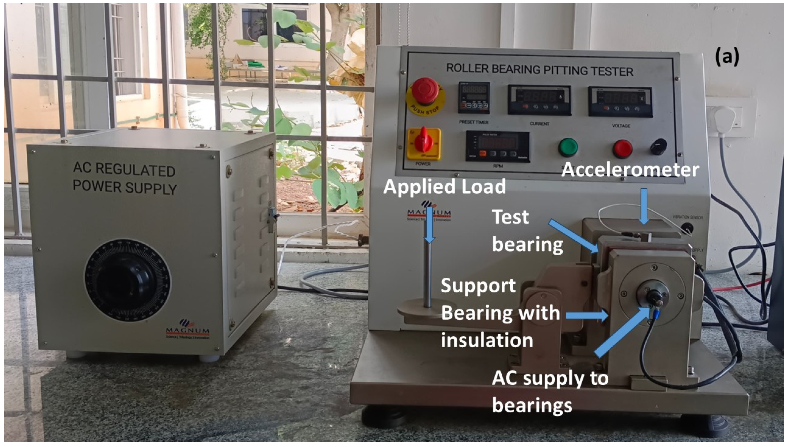
Figure 1. (a) Full bearing setup for tribo test. (b) Schematic diagram of setup.
Technologies 13 00275 g001aTechnologies 13 00275 g001b
Figure 2. Comparing the greases based on various performance parameters: (a) average current; (b) average voltage; (c) average vibrations.
Technologies 13 00275 g002
Figure 3. Parameters vs. time graphs of greases during testing: (a) current; (b) voltage; (c) vibration.
Technologies 13 00275 g003
Figure 4. Discoloration of greases after tests with electric current: (a) Grease 1; (b) Grease 2.
Technologies 13 00275 g004
Figure 5. FTIR spectrographs of grease after test without current. (a) Grease 1; (b) Grease 2.
Technologies 13 00275 g005
Figure 6. FTIR spectrographs of grease after test with current. (a) Grease 1; (b) Grease 2.
Technologies 13 00275 g006
Figure 7. Surface damages of bearing raceways without current flow in (a) Grease 1 and (b) Grease 2 samples.
Technologies 13 00275 g007
Figure 8. Formation of white etched areas in (a) Grease 1 and (b) Grease 2 samples.
Technologies 13 00275 g008
Figure 9. Optical microscope images of bearing raceway indicating failures. (a) Fresh bearing; (b) bearing raceway after the test with Grease 1 with micro pits; (c) bearing raceway after the test with Grease 2 with micro pits and fluting marks.
Technologies 13 00275 g009
Figure 10. 3D profilometer images of (a) fresh bearing raceway; (b) bearing raceway after the test with Grease 1 without current; (c) bearing raceway after the test with Grease 2 without current; (d) bearing raceway after the test with Grease 1 with current; and (e) bearing raceway after the test with Grease 2 with current.
Technologies 13 00275 g010aTechnologies 13 00275 g010b
Table 1. Chemical compositions of parts of bearing.
Bearing PartsElement (%)
CarbonManganeseSiliconSulphurPhosphorusChromium
Raceway0.9340.3810.2340.0110.0051.421
Bearing balls0.9160.3500.2400.0170.0221.370
Cage0.0640.233-0.0140.017-
Table 2. Physicochemical properties of greases.
PropertiesGrease 1Grease 2
Thickener typeLithium 12 hydroxy stearateLithium 12 hydroxy stearate
Thickener content (%)10–128–10
Base oil typeEster + PAOEster + PAO + Aromatic oil
Base oil viscosity at 40 °C46–5432–35
NLGI grade21
Drop point °C180180
Table 3. Elemental analysis of greases.
ElementsUnitGrease 1Grease 2
Lithiumppm69061905
Boronppm1213
Magnesiumppm41
Zincppm17
Phosphorusppm25542
Calciumppm5232
Sulphurppm27671816
Table 4. t-test p-values for vibration data sets.
Comparisonp-Value
Grease 1 vs. Grease 2No Current10 A
0.93550.0447
0 A vs. 10 AGrease 1Grease 2
0.14030.0594
Table 5. Iron content in grease after tribo test.
Passage of CurrentGreaseUnitFe Content
No
current
Grease 1ppm6
Grease 2ppm8
10 A
current
Grease 1ppm56
Grease 2ppm270
Disclaimer/Publisher’s Note: The statements, opinions and data contained in all publications are solely those of the individual author(s) and contributor(s) and not of MDPI and/or the editor(s). MDPI and/or the editor(s) disclaim responsibility for any injury to people or property resulting from any ideas, methods, instructions or products referred to in the content.