1. Introduction
Applications using hand gesture recognition have usually relied on one of two methods, either visual-based or inertial-sensor-based [
1,
2]. The visual-based hand gesture recognition system allows a hand gesture to be perceived without the use of any wearable devices [
3]. However, there are several drawbacks to this approach, such as complexity in modelling the hand motion and position, and the sensitivity of the system regarding lighting conditions and occlusions [
4,
5]. On the other hand, electromyography (EMG)-based recognition systems depend on muscle movement and capture surface EMG signals [
6]. This type of system has already been used to control wheelchairs [
6,
7,
8] and mobile robots [
9,
10], in addition to the electroencephalogram (EEG) brain–computer interface (BCI)-based approaches [
11,
12,
13]. This paper aims to expand the research on the topic by introducing a more accurate classification system with a wider set of gestures, hoping to come closer to a usable real-life application.
The work presented in this paper focuses on the development of a mobile robot controlled solely by human gestures. This is achieved using the Thalmic Labs Myo Armband [
14], a device for gesture recognition composed of eight different EMG sensors and one inertial measurement unit (IMU) sensor. The user’s arm gestures are captured by the EMG sensors and transmitted via Bluetooth to the microprocessor onboard the robot which analyzes the data and subsequently controls the robot movement. In this paper, a detailed design of the hardware and software for this modular mobile robot is presented along with the testing outcomes analyzed.
This paper is organized as follows:
Section 2 describes the hardware components used to build the robot, including their specifications, with details of the kinematic formulas involved in the control of a differential drive robot and how these have been implemented on the microcontroller. This section also details the Robot Operating System (ROS) basics and the classification algorithm used to recognize the gestures, followed by implementation, outcome testing and accuracy analysis.
Section 3 presents the experimental setup, controller design, ROS application and results, while
Section 4 concludes the paper.
2. Materials and Methods
2.1. Computing Devices
Raspberry Pi 3 was chosen for the single board computer (SBC) as it has 1 GB SDRAM memory, 1.2 GHZ quad-core ARM Cortex A53 CPU, 4 USB Ports and many other features at a very low price which is suitable for mobile robot projects.
The Teensy 3.2 micro controller was used in the project as it is a powerful, inexpensive microcontroller with a small footprint. An H-bridge motor driver was used to control the flow of current between the motors and to alter the current provided to turn them in the desired direction. The TB6612FNG motor driver was selected to control the motors. It can drive two motors at a maximum current draw of 1.2A constant current; meanwhile, it can also control the motion direction and speed.
2.2. Sensors
Ultrasonic Sensors are common and efficient sensors that are typically used for collision avoidance. They can detect obstacles from 2 cm to 40 cm, which is a reasonable distance for a mobile robot to detect obstacles and avoid collision upon detection.
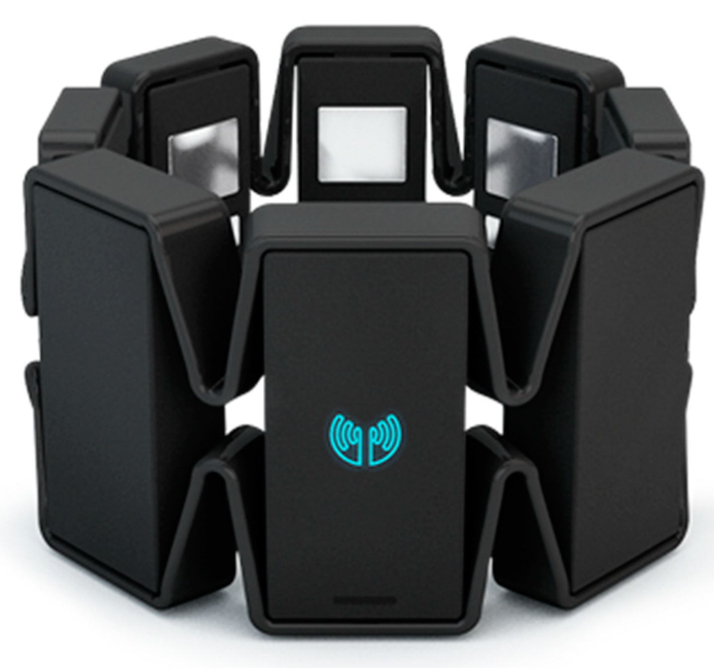
A wearable Myo armband (cf.
Figure 1) was used to detect the hand gestures by obtaining surface electromyography signals from the human arm. The Myo armband consists of 8 EMG sensors with a high sensitive nine-axis IMU containing a three-axis gyroscope, three-axis accelerometer, and a three-axis magnetometer. The 8 channels of EMG signals detected by the Myo armband are passed via Bluetooth to the Raspberry Pi where all channels of signals are classified to detect the hand gestures.
2.3. Motors and Wheels
The final weight of the mobile robot was estimated to be 5 kg with 7 cm diameter wheels. The robot moves with a speed of 0.22 m/s which requires a total torque of 1.25 kg-cm and 31 revolutions per minute. Since this is a two-wheeled robot driven by two motors, the total torque is divided into two equal halves of torque needed by each of the motors. DC motors are ideal motors as they are reasonably cheap, and the gear box increases the torque of the motor and reduces the motor speed. The geared DC motors used each had a torque of 0.7 kg-cm on the load and 158 ± 10% rpm. These motors were a suitable choice as they meet the requirements of the application.
2.4. The Robot Operating System (ROS)
The software application controlling the robot was developed using the ROS framework. The ROS structure is based on the execution of different C++ or Python scripts—called nodes—that can communicate without being aware of each other, working independently on the messages they receive and send on their topics of interest. This design encourages modularity and thus, is perfectly in line with the robot’s structure and hardware design.
2.5. The k-Nearest Neighbor (KNN) Classifier
To precisely predict a gesture from the Myo Armband, a classifier script was prepared using a KNN algorithm [
15]. The KNN algorithm computes the distance between the sample that must be recognized and all the samples used to train the classifier; the class that represents the majority among the K nearest samples—in this case, K is set to 10—is the one used to label the tested one. This algorithm was chosen because of its fast execution and accuracy when multiple classes must be recognized from a large set of parameters [
16]. Initially, the classifier was trained to recognize ten different classes, namely, rest, spread, wave out, wave in, fist, cut out, cut in, snap, ‘V’, and horn (cf.
Figure 2), but for the final application, the unused ones were removed, and this enhanced the accuracy of the classification.
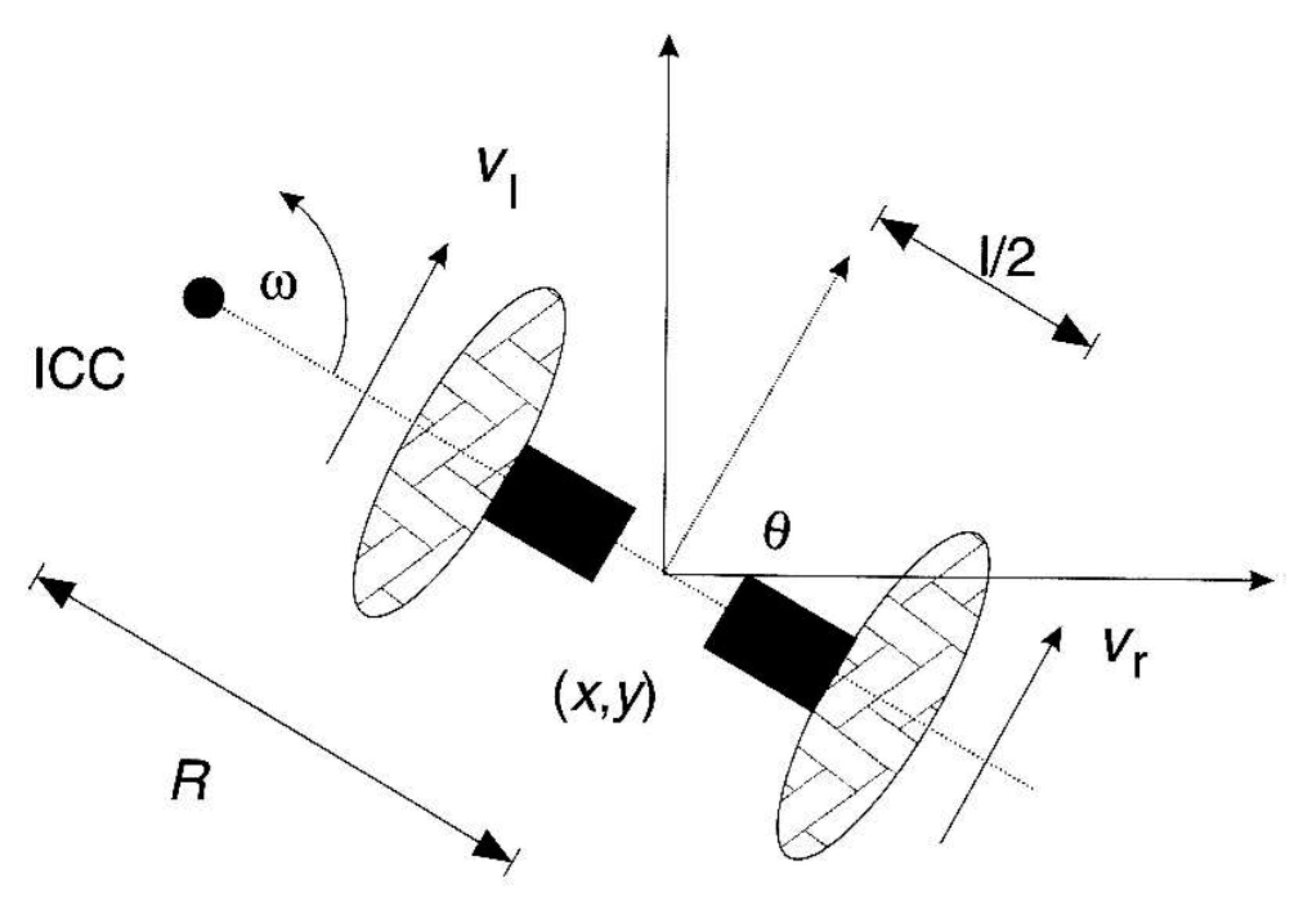
2.6. Differential Drive Kinematics
Differential drive robots are devices that are capable of moving using two independent wheels that are mounted on a common axis, each driven by a motor for forward and backward motions (cf.
Figure 3). The direction of the robot is closely related to the composition of the velocity of each wheel and rotation about a point that lies on the common axis called ICC—Instantaneous Centre of Curvature (or ICR—Instantaneous Centre of Rotation) [
17]. This is, therefore, completely different from our previous work on ROS-based bipedal robot control [
18].
Since the angular speed (
ω) at the ICC must be the same for both wheels, the following equations were used [
20]:
where
is the distance between the centres of the two wheels,
and
are the right and left wheel linear velocities along the ground, and
R is the distance from the ICC to the midpoint between the wheels. At any instant in time, we can solve for
R and
ω:
Three cases can be analyzed from the equations:
If , then this is linear motion in a straight line. R becomes infinite and ω is zero, and there is no rotation.
If , then , and this represents rotation around the midpoint of the wheel axis; the robot rotates in place.
If , then there is rotation around the left wheel. In this case, . The same is true if .
Given the angular velocities,
and
, of the left and right wheels, the linear and angular velocities,
and
, of the robot can be computed with
Vice versa, by knowing the overall velocity of the system, the velocity of each wheel can be found with
and are used as the desired velocity that is published from the ROS system to the Teensy microcontroller to drive the motors.
3. Experimental Setup and Results
Based on the discussion in
Section 2, the experiment set up is presented, and the test outcomes are shown below.
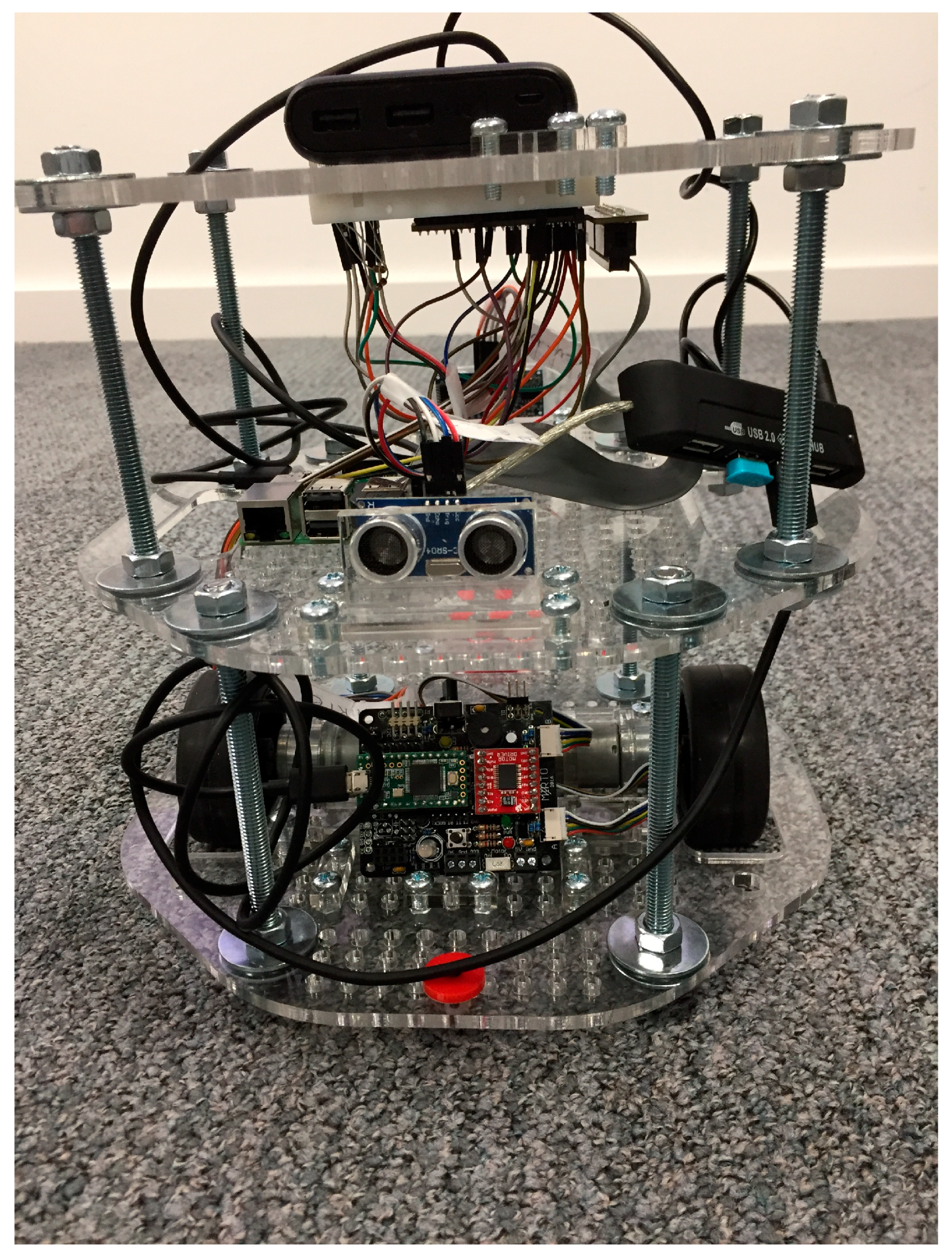
3.1. Hardware Setup
The hardware implementation of a mobile robot consists of three layers (cf.
Figure 4). The base layer incorporates two geared DC motors with an encoder, a motor board shield with Teensy 3.2, a motor bridge, and a caster wheel. The motor board drives and controls the motors. The caster wheel is used to balance the robot base.
The second layer consists of a Raspberry Pi 3 and two ultrasonic sensors facing the front and the back side of the robot for collision avoidance. The Ubuntu Mate is installed in the Raspberry Pi as the operating system, with the ROS installed as well. The Raspberry Pi receives the signals from the Ultrasonic sensors and sends the twist message to control the linear and angular speeds of the robot.
The third layer is used as the protective layer, and the breadboard is attached at the back side of the third layer for short wiring purpose. The breadboard can create a mutable circuit design between Raspberry Pi, the motor board, and the Ultrasonic sensors. A Raspberry Connector is used to connect the Raspberry Pi with the breadboard.
3.2. The Controller Design
The Arduino Teensy 3.2 microcontroller takes care of the low-level control of the actuators, translating the messages from an ROS format to PWM commands to drive the motors. To perform such tasks, a dedicated protocol, called rosserial_arduino, was used to wrap standard ROS messages, topics, and services over a serial port, so that the controller acts like a ROS node.
After the definition of all the necessary variables and the ROS related structures like the node handle, messages, publishers and subscribers, the critical function of the entire script is the callback executed when a message is received. The cmdVelCB function receives a Twist message carrying the desired speed commands issued at the higher level published on the topic /cmd_vel, and, using Equations (7) and (8), computes the velocities of left and right wheels which then are used as direct PWM commands on the motors.
At the same time, the encoders embedded on each motor provide the actual speed of the wheels. Depending on the size of the wheel and the encoder counts during the rotation, it is possible to calculate the travelled distance and the speed via dead reckoning:
where
D is the distance, r is the radius of the wheel,
C the current encoder counts and CR is the total counts per revolution. From (9), the
and
for each wheel can be found:
where
T is the time passed during the movement. The computation of the speed from the encoder counts is executed in a time interrupt every 0.2 s. From (11),
and
are published on the topics
/left_wheel_pub and
/right_wheel_pub. These topics are available to the ROS system to monitor the robot. By using Equations (5) and (6), the current linear and angular velocities of the robot are calculated and published in a ROS Twist message on the topic:
/robot_vel_pub. 3.3. KNN Classifier Design and Test
To enhance the KNN classifier performance in our work, the EMG samples received were preprocessed and the features were extracted. Different signal lengths were tested to find the best compromise between accuracy and time, and it was decided that five samples would be used for the feature extraction. By analyzing the graphs of the various EMG channels, it was noticed that during the execution of a gesture, the signals did not show significant variation, but rather had steady recurring values. Since, in the final application, each gesture must be recognized while it is being held and not during the transition between gestures, we decided to use features that could cancel out the average value of the different channels while the gestures were performed, rather than looking for variation in the signal itself. Several studies have explored potential feature selection approaches for raw EMG signals [
21,
22]. The features chosen for this work were Integrated EMG (IEMG), Mean Average Value (MAV), Simple Square Integral (SSI), Root Mean Square (RMS), Log Detector (LOG) and Variance (VAR) [
21,
23,
24,
25], primarily because these features are easy to compute and are computationally less intensive:
By applying these six features to the signals of the eight Myo’s channels a vector of forty-eight values representing a gesture is obtained. To avoid redundancy or to reduce cross-class typical values, the vector was transformed applying the Principal Components Analysis (PCA) algorithm. The PCA is an algorithm that applies an orthogonal transformation to a set of elements and extracts the principal components of it [
26].
The algorithm was tested on four subjects by recording samples of their gestures. The recording procedure was executed with the subject holding each gesture three times for five seconds and resting for five seconds between each. The samples were recorded only when a key was pressed on the keyboard, so there were no transition samples recorded that had to be discarded. Then, each gesture was recorded again for five seconds to obtain a set of samples to be used for the testing. The samples were tested using different
k values for the KNN algorithm and different numbers of principal components after the PCA transformation. In the end, it was chosen to use a
k value of 15 and to keep nine components. The first accuracy test showed good results for most of the gestures, but not all of them. Better results were achieved by extracting fewer features from the signals, thus reducing the presence of cross-class typical values. The final version of the classifier applied only two features—MAV and RMS—and showed better performances, both in terms of accuracy and classifying time. Finally, the performances were again improved when the classifier was modified to suit the final application, since the number of classes that had to be recognized was cut down from ten to six—only rest, wave out, wave in, fist, cut out and cut in were kept. The accuracy rates of the three different algorithms can be seen in
Table 1,
Table 2 and
Table 3.
It must be considered that the EMG signals produced by a person’s muscles while performing a gesture can change depending on the person’s conditions. Elements like the quantity of caffeine and other substances in the body or the level of stress affect the values read by the Myo Armband and thus, the classifier performance. The accuracy tables shown in this section refer to tests done a few minutes after the train samples were recorded, so that the subject status was as similar as possible. While testing the controls moving the robot, it was observed that sometimes the classifier is not as reliable as seen in the tests. This may impact the robot’s performance, but rarely in an excessive way.
3.4. Robot Application
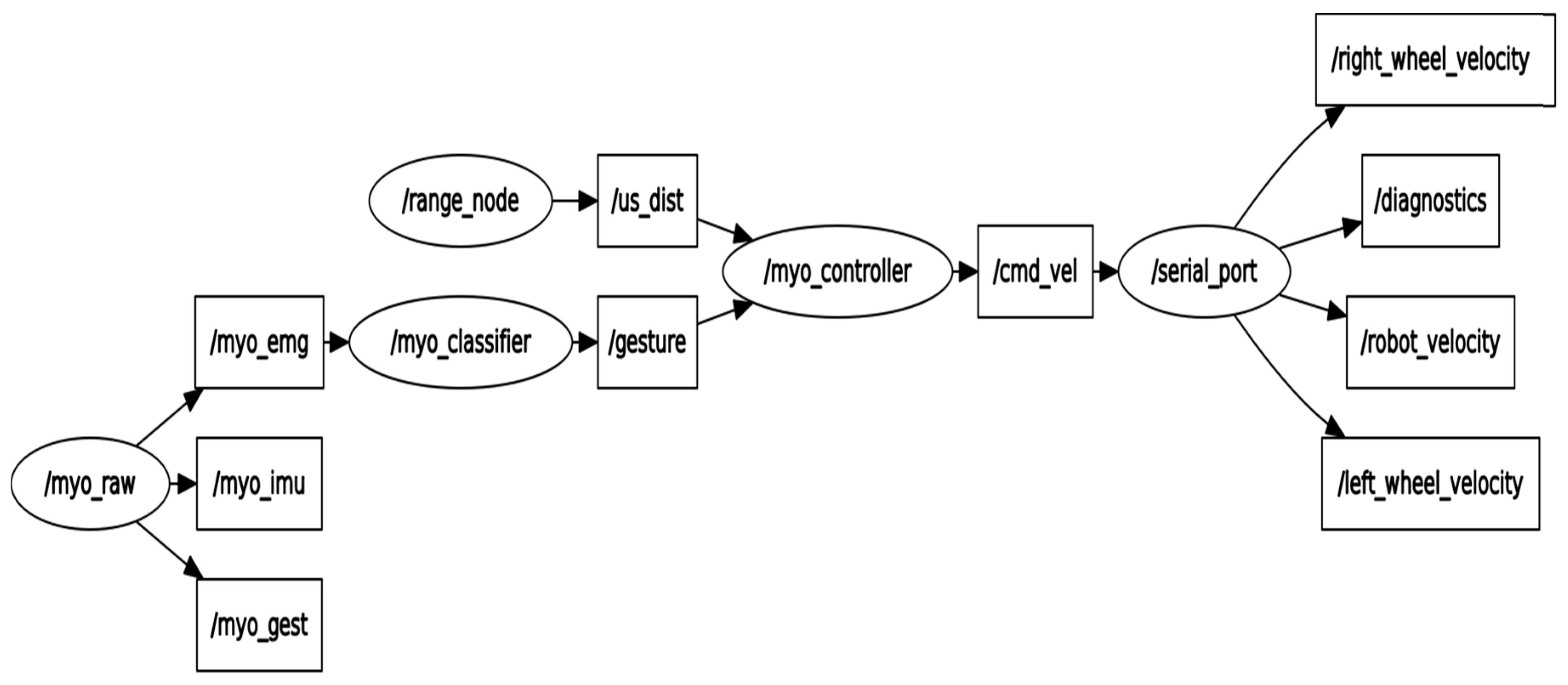
The ROS framework is used for the robot application, which is composed of five nodes; its rqt graph is shown in
Figure 5. The nodes myo_interface.py and ultrasonic_node.py read the data of the Myo Armband and the two ultrasonic range sensors, respectively, and publish them. The range data is published on only one topic and each message is labeled according to the sensor that produces it. The classifier_node.py implements a ROS interface for the KNN gesture classifier that was developed separately and which was described in
Section 2.5. It subscribes to the EMG data topic and publishes the recognized gestures on a specific topic. The controller_node.py uses both the gesture and the range data to produce a cmd_vel message. The last node—the serial_port—is implemented by ROS and it allows the application to interface with a microcontroller as it is a ROS node. It receives the cmd_vel Twist messages and forwards them to the motor controller and publishes the robot velocity.
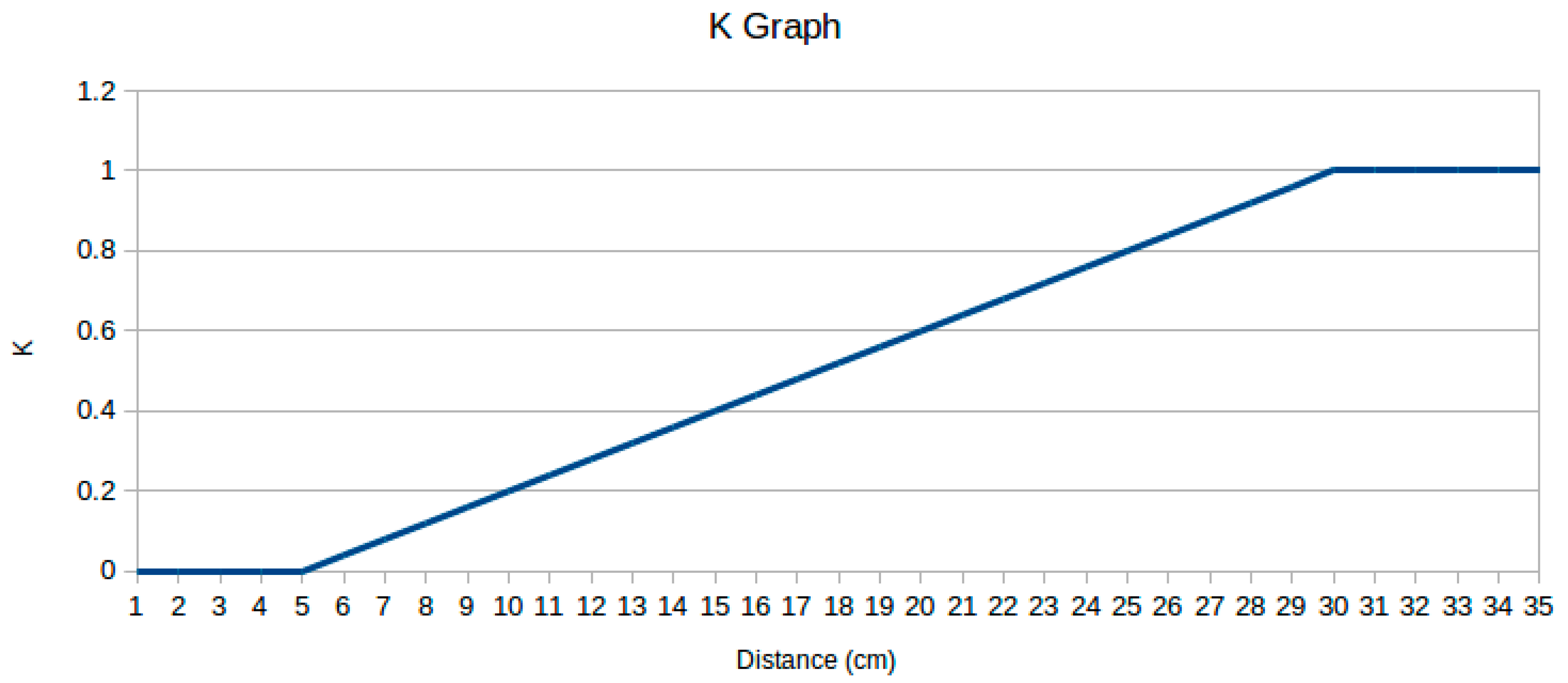
The robot is controlled by six different gestures: rest, fist, wave out, wave in, cut out, and cut in. These are used to move it at a set linear and angular speed. Fist makes the robot move forward, cut out and cut in make it turn right and left on the spot, wave out stops it, wave in makes it move backwards, and finally, the rest position is used to continue the use of the command of the last gesture received. While the robot is moving forward or backward, the relative range sensor is checked to slow it down or eventually, stop it. To do this, the linear speed is multiplied by a K factor that depends on the range data detected by the sensor that is pointing in the same direction as the speed. This K is equal to 0 when the distance is 5 cm or less. It grows linearly to 1 from 5 cm to 30 cm, and above that, it is always set to 1. (cf.
Figure 6).
During real-time tests, it was noticed that while holding a gesture, one sample could be misclassified, and that this could impact on the robot’s efficiency. Thus, we chose to modify the classifier_node.py to improve its accuracy. The node now stacks up the samples from the emg before beginning the classification. When it reaches fifteen samples, it classifies the whole signal received using a sliding window of five samples, thus getting ten predictions. If at least nine of them belong to the same class, then the gesture is accepted; otherwise it is rejected, and the node starts stacking up new samples without producing any result. This process increased the time required to select a gesture, but it also produced good results by increasing the precision of the controls and it still maintains a classification time low enough to have an almost immediate response from the robot. The frequency at which the EMG samples are received is 100 Hz—which means one sample each 10 ms—and the time required by the algorithm to extract the features, select the principal components and calculate the K neighbors varies between 3.1 ms and 3.3 ms. Rounding up the classification time to 3.5 ms to get the worst time possible, it takes, in total, 185 ms for the script to recognize a gesture—150 ms to receive the fifteen samples and 35 ms to compute the ten predictions.
3.5. Results
Since both the robot’s structure and controls were designed from the ground up, it was necessary to test their efficiency. At first, the robot was driven for some time by all subjects to make sure it could be controlled without any problems. No data was collected during these free tests, since the objective was just to check the presence of possible problems. For this test, the robot’s linear velocity was set to 0.22 m/s, and its angular velocity was set to 60°/s. During the test, these values proved to be a good compromise between speed and ease of control. It was observed that the disposition of the hardware components and their weights could affect the speed of the robot and cause it to gain angular speed during the forward and backward movements. This was solved positioning the boards, breadboard, and battery in a symmetrical way with respect to the robot’s linear movement direction. The range sensors worked well, even though it was noticed that they performed better when detecting flat surfaces. When pointing to an irregular obstacle—a leg for instance—the read values were more variable, resulting in sudden changes in speed. We also checked how the distance between the subject and the robot could impact on the controls. For this purpose, the subjects stood in a corridor 20 m away from the robot, with a closed door in between. There was no delay noticed in the robot’s reaction to the commands.
The next test concerned the minimum distance and rotation that could be performed by the robot. This test was necessary because the way the robot is controlled implies a delay between an order and its execution and thus, a minimum time span between two commands. This means that between a movement and a stop command, the robot will always cover a minimum distance. The test was performed with the subjects giving a movement command—forward for the first test and a left turn for the second one—and then a stop command as soon as possible. During these tests, the robot was driven over a sheet of paper on which its reference starting positions were signed, so that it was possible to calculate the differences between distance and rotation later. The test was repeated five times by each subject. The results can be seen in
Table 4 and
Table 5. On average, the minimum distance covered by the robot was 12.79 cm, and the minimum rotation was 38.35°.
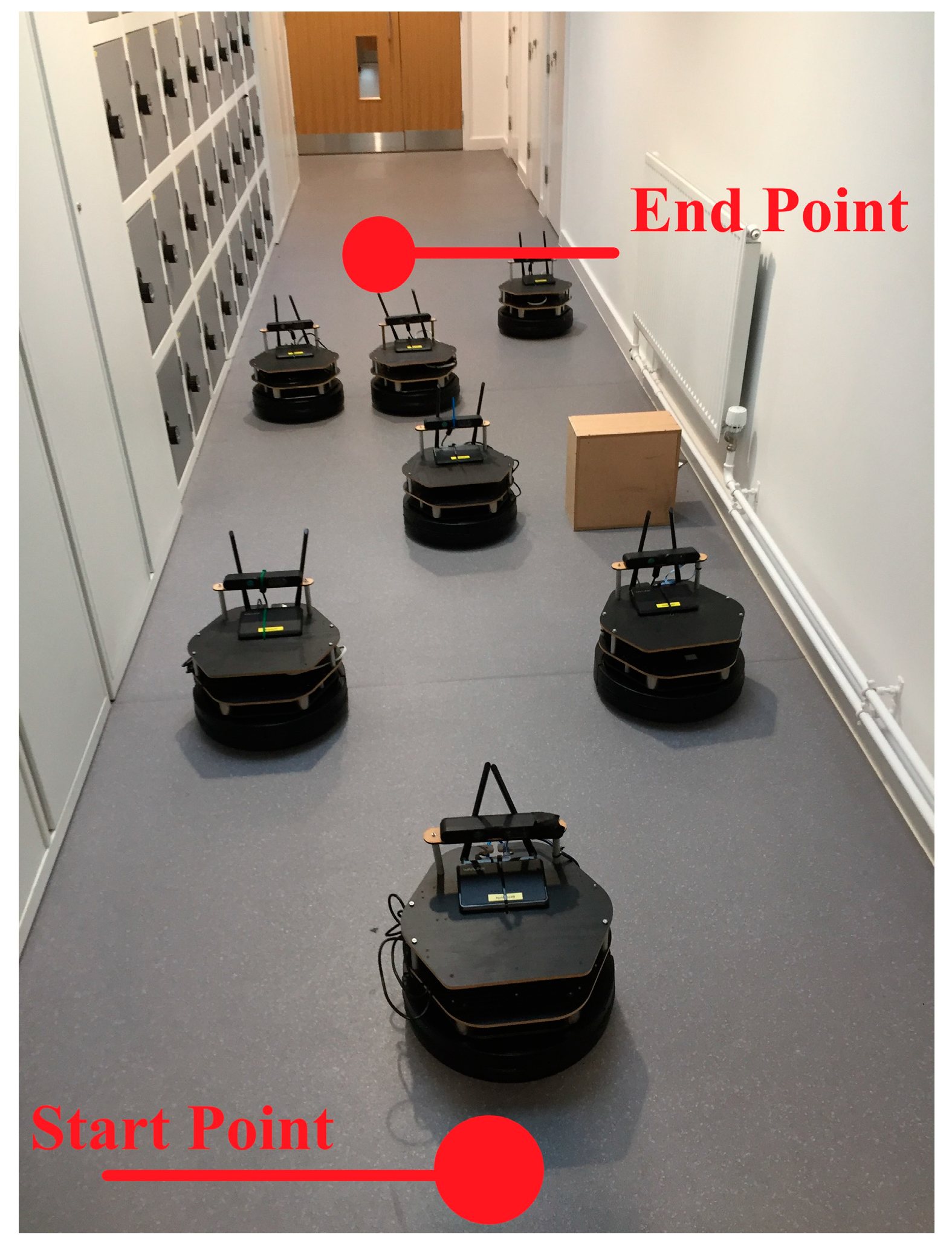
In the final test (cf.
Figure 7), the subjects drove the robot from a start point to an end target while avoiding obstacles. The distance between the two points was 6 m. Each subject completed the task two times, and for each one, the time duration to complete the task and the number of commands required were noted. The results are shown in
Table 6, and a sample video demonstration by one subject is shown in [
27]. They vary a lot despite the overall good accuracies found in the classifier test, probably because—as stated in the previous section—the classifier’s accuracy depends on the subject’s state.
4. Discussion and Conclusions
In this project a mobile robot base was developed. The Myo gesture control armband was used to obtain the surface EMG signals from the human arm which were then classified using a KNN algorithm to recognize the gestures.
Initially, the algorithm was programmed to recognize 10 different gestures. Four test subjects were tested to calculate the accuracy of all classes on each subject. Then, unused classes were removed which, in turn, improved the accuracy of the ones been used. The robot application comprised five ROS nodes that were used to read the data signals from the Myo armband and ultrasonic sensors, detect gestures, and control the movement of the robot. Several tests were conducted with four subjects to test the feasibility and the efficiency of the robot and the software system.
This approach proposed here to control mobile robots could become a valid method thanks to its direct interaction with the human body that makes it quick and intuitive. To make it a viable option though, it will be necessary to overcome the flaws found during the tests. First, it was observed that the delay between gesture execution and gesture recognition can strongly affect the minimum distance and rotation that the robot can cover, thus influencing its maneuverability, making a compromise between speed and ease of control necessary. Second, during the track test, it was noticed how the processing of physiological signals and the way they can vary greatly due to a huge number of factors sometimes make the gesture recognition algorithm too unreliable to be usable. This last problem could be solved in the future by adding the possibility to do quick and non-permanent re-training on the subject to adjust the values of one or two gestures to check how the average has moved.
Due to time constraints, some features that were supposed to be developed, were not included in the end. Future improvements will primarily focus on integrating these features. For instance, a PID control for the motors, a wider number of commands that allow the combination of linear and angular speed, and the possibility of increasing and decreasing the robot’s speed using the Myo’s IMU sensor.


