Abstract
With the surging interest in electric vehicles (EVs), there is a need for advancements in the development and dismantling of lithium-ion batteries (LIBs), which are highly important for the circular economy. This paper introduces an intelligent hybrid task planner designed for multi-robot disassembly and demonstrates its application to an EV lithium-ion battery pack. The objective is to enable multiple robots to operate collaboratively in a single workspace to execute battery disassembly tasks efficiently and without collisions. This approach can be generalized to almost any disassembly task. The planner uses logical and hierarchical strategies to identify object locations from data captured by cameras mounted on each robot’s end-effector, orchestrating coordinated pick-and-place operations. The efficacy of this task planner was assessed through simulations with three trajectory-planning algorithms: RRT, RRTConnect, and RRTStar. Performance evaluations focused on completion times for battery disassembly tasks. The results showed that completion times were similar across the planners, with 543.06 s for RRT, 541.89 s for RRTConnect, and 547.27 s for RRTStar, illustrating that the effectiveness of the task planner is independent of the specific joint-trajectory-planning algorithm used. This demonstrates the planner’s capability to effectively manage multi-robot disassembly operations.
1. Introduction
Electric vehicles (EVs) have experienced rapid growth in the last decade due to their environmental friendliness, contribution to energy security, and savings in operating/maintenance costs. However, this growth has increased the use of lithium-ion batteries (LiBs). The volume of expended LiBs is anticipated to reach 2 million metric tonnes per year by 2030 [1]. Therefore, the need to dispose of these batteries has surged. Although LiBs are a key component of home energy storage systems, their production and disposal processes can lead to various environmental challenges. This sector is increasing its efforts to effectively recycle used household batteries and develop second-age applications [2], which are being prioritized in the circular economy for the monetary savings and benefits they can provide.
While the rise of EVs highlights their environmentally friendly and economic advantages, an important area for the sustainability of this technology is the recycling of LiBs using robotic technology. In this context, robotic battery recycling technology, which has drawn great attention but is still in the research phase, has the potential to offer an effective solution to the recycling process. The development of this technology is generally included in studies focusing on special tasks such as screw removal [3,4,5,6,7,8], grasping [9], and cutting [10].
Disassembling batteries is a critical operation within industrial robotics and automation processes, particularly relevant to EV applications. These applications often encompass the maintenance, repair, or recycling of EV battery packs. Central to automating these operations are task planners, which equip robots with the capabilities to identify, manipulate, and accurately sequence the placement of objects. A proficient task planner is essential for the precise, safe, and logical execution of battery removal tasks. Moreover, achieving the timely, efficient, and safe dismantling of batteries is imperative for meeting economic and sustainability objectives.
Choux et al. [11] and Wang et al. [12] previously proposed task planners with a robot arm framework for EV battery disassembly. However, task-planning processes with a single robot can lead to limitations in terms of efficiency, especially when faced with complex and large-scale tasks. In this context, existing studies in the literature generally do not include multi-robot systems, and this has limited the time performance, especially in time-critical applications.
The differences between disassembly methods are summarized in Figure 1. The multi-robot system excels in most categories, notably in process time and workspace adaptability, positioning it as the most effective option despite a marginally increased risk of collision. The single-robot system represents a middle ground, performing well overall but with its efficiency constrained by its operational workspace. However, it offers high safety and a low collision risk. The manual method presents varied outcomes; it is efficient and poses a low collision risk but falls short in safety and only moderately adapts to workspace constraints. Hence, this paper emphasizes the importance of using multiple robots in disassembly settings. Some studies demonstrate that the time difference between a manual process and a robot-automated process is minimal [13], with a robot taking only 1.05 s for every second a human takes for a task. It is also shown that adding more humans can increase the disassembly speed. Considering this human-to-robot factor, it can be assumed that more robots will perform tasks faster and within a larger workspace.
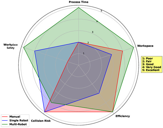
Figure 1.
A visual comparison of three disassembly methods—manual, single-robot, and multi-robot—across five critical operational aspects: process time, workspace, efficiency, collision risk, and workplace safety. Each aspect is quantitatively rated on a scale from 1 to 5, where 1 indicates the least favourable outcome and 5 indicates the most favourable.
The main aim of this study is to design a task planner (Figure 2) that can perform the disassembly of an EV battery pack without prior knowledge of a specific product location, creating automatic disassembly plans and sequences. The key functions of the proposed task planner consist of determining the LIB components and their locations, calculating the movement cost of the components according to the distance between them and the robots, logically sorting the objects according to the distance, and finally, picking and placing the objects by moving the robot to the determined disassembly locations. By using more than one robot in the environment, the disassembly and removal tasks, which are the main steps of battery removal, are accomplished without collision. The disassembly steps were simulated in Gazebo [14], a simulation environment. To demonstrate this, the object detection approach was performed with YOLOV8 to obtain the object positions and dynamically allow the robots to select which task and object to disassemble to complete the primary task. The approach, successfully implemented, was validated through experiments using different motion planners in the Gazebo environment. These experiments involved the disassembly of a simplified version of the NISSAN e-NV200 battery pack, which contained its various components. This served as a proof of concept for our proposed multi-robot hybrid task planner, which is designed to operate in various scenes.
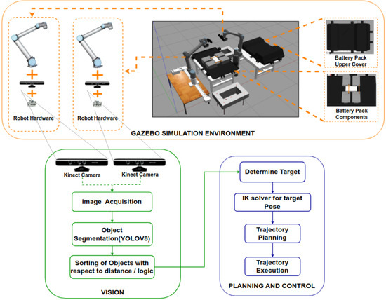
Figure 2.
A graphical overview of the task planner designed in the simulation environment, the proposed vision algorithm, and the planning and control algorithm.
2. Related Works
Many studies have investigated battery disassembly, typically categorized into two groups: semi-autonomous and fully autonomous. Semi-autonomous studies involve robots assisting humans in collaborative tasks, whereas fully autonomous studies entail robots undertaking complex and repetitive tasks independently. Semi-autonomous approaches often raise safety concerns, as humans and robots share the same workspace, potentially complicating human–robot interaction and necessitating the precise management of safety protocols. Conversely, autonomous systems offer significant advantages in terms of speed, reliability, and performance while reducing reliance on human labour.
Wegener et al. [4] and Chen et al. [5] presented semi-autonomous scenarios in which robots perform simpler tasks, such as removing screws and bolts, while humans engage in more complex and diversified tasks. The work by Kay et al. [10] highlighted an approach designed to support human–robot cooperation. It analysed operations, mainly monitoring human workers, including their times and actions, which included cutting and grasping, to understand the disassembly process. In another study [15], the focus was on tracking different types of robots in a modular combination using a behaviour tree-based framework, with battery parts placed in a straight line, but failed to focus on a logical disassembly process and just dealt with the obtention of previously disassembled components.
In fully autonomous operations, disassembly is typically carried out using a single robot. Wang et al. [12] conducted a study aiming to separate nested objects using a simulated environment. In a study by Choux et al. [11], the robot performed a hierarchical disassembly process but was limited to the predefined hierarchy, and a single robot was used. Our framework implements something similar but with dynamic hierarchy updates and with multiple robots. Furthermore, autonomous research endeavours to enhance disassembly efficiency by enabling robots to plan and execute repetitive activities in unstructured situations while receiving visual and tactile inputs. Haptic devices have been utilized in the literature to aid in robotic disassembly [16,17]. For instance, tactile devices were employed to develop a screwdriver robot that transfers the sensations felt by humans during the removal of screws to robots [17].
Continuous developments in the field of robotics have led to significant advances in the design and implementation of robot systems capable of performing complex tasks. Autonomous systems encompass those developed with a single robot as well as those involving the cooperation of multiple robots. The utilization of multiple collaborative robots has gained prominence in the industry due to its effectiveness in minimizing labour costs and production errors. When robots share the same environment, they can typically cooperate smoothly, with minimal risk of collision, as long as they do not intrude into each other’s workspaces. However, coordinating multiple arms introduces new challenges, including computational difficulties stemming from increased degrees of freedom and the combinatorial increase in operations that multiple manipulators can perform, such as handoffs between arms. Palleschi et al. [18] addressed the complexity arising when multiple robots share the same environment. Although their approach reduces planning complexity, the solutions found do not allow for the simultaneous execution of actions specific to multi-robot systems, which our framework does allow.
Tianyang and other researchers have reported on a method developed to coordinate tasks performed by multiple robots simultaneously [19]. This approach consists of a motion planner using the RRT-connect algorithm and a time scheduler solved by permutation. While this method could be extended to up to five robots, it was observed that it timed out in the case of six robots due to computational limitations. A study by Zhu et al. focusing on the flexible job scheduling of multi-robot manipulators operating in a dynamic environment and the dual-resource FJSP (flexible job shop scheduling problem) was carried out [20]. The paper used a gate layer neural network feature that addresses multitask coordination. However, since this feature was designed to be subjective within their framework, it led to a poor discrimination of differences between multiple tasks. To avoid this problem, in our proposed task planner, multi-robot multitasking complexity is prevented by calculating the distance cost of robots to objects and synchronized movement. In this way, robots select objects in the environment based on distance and update the image before each robot begins its targeted task.
Touzani et al. presented an effective iterative algorithm that produces a high-quality solution to overcome the task-sequencing problem that arises from the use of multiple robots [21]. Moreover, their proposed framework (or algorithm or pipeline) includes robot–robot and robot–obstacle collision avoidance. They also planned a collision-free trajectory towards the targeted position. Our proposed task planner plans a collision-free trajectory, similar to the method mentioned in the work of Touzani et al. Therefore, the risk of collision arising from the use of multiple robots is effectively prevented.
Inspired by human behaviour, another study aimed to build a wooden block using dual arms [22]. In line with this targeted work, an assembly planner is proposed to plan the optimal assembly sequence. Although the use of multiple robots has become quite common recently, a limited number of studies have focused on the disassembly process. Fleischer et al. [23] discuss the importance of sustainable processing strategies for end-of-life products, with a particular focus on the disassembly process of traction batteries and motors in battery EVs. And they proposed the Agile Disassembly System. In the presented concept, two operation-specific six-axis robots are used kinematically. One robot is responsible for handling operations, while the other robot is used for sorting operations. Similar to the aforementioned study, our proposed task planner enables multiple robots to perform their tasks effectively by sorting objects according to distance and logic from the robots. In our planner, there is no task distinction between robots; instead, each robot can perform all operations based on dynamic logic and hierarchy. This approach allows tasks to be completed more quickly and efficiently while also reducing the risk of collisions. With these features, the proposed planner offers a high-performance solution to successfully manage complex tasks of multi-robot systems.
Task planners increase flexibility and efficiency in robotic applications, effectively managing multiple components and modules. Recently, there has been a lot of research focusing on behaviour trees to automate robotic manipulation tasks [24,25]. In these studies, the behaviour tree library generally emerged as the most widely used method. Behaviour Trees (BTs) serve as models for designing robotic behaviours and emerged in response to real-world challenges. BTs are tree structures that outline the steps robots must follow to complete certain tasks, thus modelling robots’ decision-making processes and allowing them to adapt to environmental conditions. In addition, Torres et al. [8], in a study on the effective use of multiple robots in the same working environment, aimed to assign different tasks to each robot at different time intervals. In this decision tree-based study, the authors distinguished two categories of tasks: common and parallel. They used decision trees to allocate work across robots, reducing disassembly time. The suggested task planner prevents robot collisions by assigning each robot a specified task at a specific moment, considering each robot’s workspace. However, this is incompatible with operational robots performing the same task concurrently. In general, reviews in the literature indicate that automatic disassembly operations for EV batteries are mostly carried out with the use of a single robot with vision systems and some task planning, but they lack the ability to cope with uncertainties that arise during disassembly and are mostly incapable of being generalized to new battery models [11,12]. This study aims to address this lack of multi-robot systems and the need for adaptation to changing component positions and task order, resulting in an enhancement of efficiency for automated disassembly operations. The proposed task planner has the ability to swiftly adapt to changing object locations, giving it an advantage in terms of flexibility and practical applicability, especially when having multiple robots interacting with the disassembly components. Consequently, the variations and uncertainties that arise in the process can be effectively addressed, leading to more efficient and reliable operations.
This article is organized into several key sections. Section 2 discusses in detail how the conducted study relates to the literature. In Section 3, general information is presented about the created simulation environment and the task-planner-driven algorithms used in this environment. Section 4 discusses the experimental setup in detail, providing information about the hardware, software, and other relevant components used for the experiments. Finally, Section 5 contains the results of the conducted study, presenting a detailed performance evaluation of the proposed task planner using different planners in a simulation environment.
3. Materials and Methods
In this section, a detailed review of the materials and methods used in our robotic system is presented, which was developed to efficiently disassemble EV battery packs using multiple robots and place their components in specified locations. This research was carried out using an open-source 3D robotic simulation tool called Gazebo to simulate the actions. Gazebo allows the creation of a realistic simulation platform using CAD models of real-world objects from the work cell (battery pack cell, in this case). Additionally, in this research, environmental images were trained using YOLOV8 [26]. It aims to enhance the visual perception capabilities of robots to successfully perform specific tasks based on the detected object.
3.1. ROS/Gazebo
Gazebo allows the realistic modelling, visualization, and control of robots, sensors, environments, and physical interactions. Its simulation environment is easily created by using CAD models of real-world objects to prepare environments that closely resemble real-world conditions. Its powerful physics engine effectively utilizes realistic simulations, enabling robots to react more closely to real-world conditions. Additionally, this simulation environment is especially compatible with the Robot Operating System (ROS) and is widely preferred in the development and testing of robotic applications.
To simulate the robots and validate the algorithms through the ROS/Gazebo, a dedicated package was developed that facilitated testing the algorithms under real-world conditions to identify and address potential issues. As depicted in Figure 3, the work cell we designed comprises two 6-degree-of-freedom UR10 robots for removing battery packs, each equipped with vacuum grippers, a contact sensor, and a Kinect RGB-D camera for sensing. One of the primary reasons for utilizing the Kinect camera in this study is its capability to provide RGB and depth images. The depth sensor of the Kinect enables the measurement of object distances in three dimensions, facilitating more accurate tracking of object interactions with the environment. Additionally, Kinect cameras are generally cost-effective and have a more accessible price point compared to other sophisticated sensing systems.
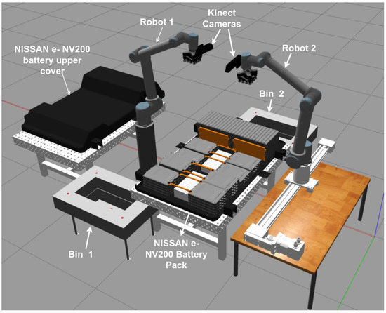
Figure 3.
An illustration of the simulation environment with a battery pack and two UR10 robots with vacuum grippers and Kinect cameras attached to the end-effectors.
The Gazebo simulation environment presents challenges when attaching or stacking objects, often resulting in objects appearing nested within each other during simulation. As a result, in the literature, objects are typically either laid flat on the ground [15] or imported as a single part [27]. Researchers working on Gazebo simulations usually add the physical properties required for each object in a scene by utilizing XML files [12].
In the Gazebo simulation environment, unlike the real environment, some problems, such as the uncontrolled movement of objects during object interaction, were encountered. Some physics features of the objects in the simulation environment were disabled, and the XML files were edited accordingly with the required physical properties. Moreover, to ensure flawless operation and minimize the risk of collisions for the two robots, we integrated them using the MoveIt platform. ROS MoveIt is a software framework that has been successfully used in tasks such as robot motion planning, kinematic solutions, motion execution, and collision avoidance [28]. A MoveIt file containing information for the two individual robots from a URDF was created to ensure that the robots worked cooperatively and without colliding. This file enabled both robots to move in a coordinated manner within the environment. MoveIt, equipped with collision avoidance motion-planning capabilities, allows two separate robots to operate in a coordinated manner. It creates a motion-planning framework using robot information from URDF files and incorporates various collision avoidance strategies. In this way, both robots can move safely within the environment, facilitating collaborative work.
3.2. Proposed Task Planner
The task planner presented in this study strategically determines disassembly action orders by thoroughly analysing data provided by a Kinect RGB camera and subsequently executes these decisions by communicating the results to the controller of the industrial robot (Figure 2). The task planner comprises several steps: image acquisition, object segmentation, hierarchy selection, motion planning, and object grasping and placement. This planner orchestrates the task process of battery pack disassembly and removal, coordinating the actions of two robots.
3.2.1. Image Acquisition
Image acquisition is the first stage of task planning. The cameras used in the simulation environment are integrated into the end-effectors of the robots, allowing them to acquire images of the environment as they move. This system captures and analyses environmental information through Kinect cameras (Figure 2). In the proposed task planner, robots start taking images from the environment when they are in the home position. After this, the object positions are detected and sent to the planning and control algorithm, and then the movement planning of the robots is carried out.
3.2.2. Object Segmentation (YOLOV8)
YOLOV8’s adaptable algorithm efficiently handles diverse data and training sets for effective performance across various applications. These features make YOLOV8 a powerful option for use in battery pack disassembly and other disassembly scenarios. The components used in this study include screws, battery modules, battery packs, plates, leaf cells, and cables, which we generated our own YOLO dataset on.
An object detection model like YOLOv8 predicts a bounding box (object boundaries) and a mask for each object. Masks enable the more detailed and precise identification of objects, allowing for the determination of precise pixel boundaries around objects and a more accurate representation of their locations within the image. In this manner, masks facilitate the utilization of object detection models in more detailed and precise segmentation tasks.
Object segmentation accomplishes the task of determining clear object boundaries by assigning each pixel in an input image to a specific object class or background. The algorithm estimates the object’s position utilizing normalized coordinates obtained in Equation (1). The , , , and variables given in the equation are the x-coordinate of the bounding box centre, the y-coordinate of the bounding box centre, the width of the bounding box, and the height of the bounding box, respectively.
YOLOv8 uses a single large model. This model can analyse an image in a single process, which is advantageous for real-time object detection applications. The algorithm divides the image into a grid and detects the objects for which each cell is responsible. Each cell estimates the presence of a particular class and the coordinates of the object’s bounding box.
In this study, Algorithm 1 is utilized for object segmentation. The vision algorithm involves image processing procedures acquired from the simulation environment. In the initial stage, the pixel coordinates (u, v) of the objects are obtained using the camera information retrieved from the simulation environment. This pixel coordinate information is then directed to the camera calibration node and converted into metres (X, Y, Z), as shown in Equation (2). After camera calibration, two-dimensional camera coordinate information is transformed into three-dimensional coordinate information. Subsequently, various transformation processes are applied to determine the coordinates relative to the robot. Finally, the obtained coordinate information is transferred to ModelState, which is the ROS message type created to direct the movement of the robot.
| Algorithm 1 Vision algorithm. |
|
In Equation (2), s represents the scaling factor, [R t] represents the camera’s extrinsic parameters (where R denotes rotation and t denotes translation to the world frame), and K represents the intrinsic camera parameters, which are described as follows:
where f is the focal length, m is the scaling factor in x and y, and (u,v) is the primary point.
Determining the distances of objects relative to the robots and then ranking them in order of priority is a critical step before they are integrated into the motion-planning module. This is because multiple robots are used in the same work cell, with the robots needing to share the tasks between them to complete disassembly. Each object has a priority order based on its placement sequence. The priority order is as follows: the cover of the battery model, screws, cables, plates, battery modules, and then leaf cells. This priority order is activated after calculating the distance between the robots and the objects, which simultaneously sorts the objects accordingly. The purpose of calculating the distance between the objects and the robots is to optimize the task-planning process by saving time and making the overall process more efficient. Once all these stages are completed, the resulting priority list is transferred to the motion-planning module with a continuous flow of information from the Kinect RBG-D camera.
3.2.3. Object Grasping and Placing
The APIs from MoveIt provide functions for setting the robot’s configuration and performing motion planning, so users can execute motion planning and control the tasks of the robot. Additionally, the Planning Scene Interface provided by MoveIt offers access to essential functions, such as collision avoidance, enabling users to create more precise and reliable plans. The OMPL (Open Motion Planning Library) planner is preferred as a component of the MoveIt framework for robotic motion planning. OMPL provides various planning algorithms, enabling robots to generate diverse motion plans in the free configuration space, and is integrated into the MoveIt framework. To initiate the simulation, it is important to initialize all relevant functionalities required for the framework, such as Gazebo world, frame transformation, vision, and control in ROS nodes, and establish communication via ROS threads on them. A motion-planning algorithm is employed for object detection and planning, as shown in Algorithm 2. The first step of the motion-planning algorithm is the positioning of the robots in the home position.
When the robots reach the starting position, they begin scanning the area and taking images from the cell, as seen in the flowchart in Figure 4; Algorithm 1, the vision algorithm, comes into play at this stage. The coordinate information obtained from vision is sorted based on its proximity to and priority for the robot. It is then verified to be within 85% of the maximum robot workspace before being sent to the motion-planning node. Before any movement in the working space of the robots, the vision information is updated. In this way, accurate and up-to-date information about the objects removed from the environment by the other robot is available.
| Algorithm 2 Moveit planner battery disassembly process. |
|
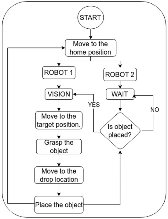
Figure 4.
Developed task planner flowchart.
This enables a robot to dynamically plan effective motion by preventing it from travelling to the wrong locations based on previous information. The algorithm relies on the synchronized movement of the robots. Initially, Robot 1 moves to the object’s location while Robot 2 remains stationary to facilitate object retrieval by Robot 1. Once Robot 1 delivers the object to the drop point, Robot 2 repositions itself using updated data and proceeds to collect the next item. Later, when Robot 1 completes its task and returns to the starting position, Robot 2 transports the retrieved object to the drop point. This synchronized process involves interdependent motions between both robots.
4. Experimental Setup
The proposed task planner was tested using two UR10 robots in a battery disassembly task, composed of a Nissan NV200 EV battery pack consisting of 16 leaf cells (grouped into stacks of 4 modules) with interconnected screws and cables, in addition to the upper cover of the battery pack. The experimental environment is shown in Figure 5. Two UR10 robots equipped with vacuum grippers are positioned opposite each other. RGB cameras are mounted on the end-effectors of the robots. These cameras are utilized to recognize the objects within the battery pack model on the table.
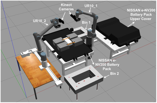
Figure 5.
An illustration of the simulation environment with a battery pack and two UR10 robots with vacuum grippers and depth cameras attached to the end-effectors.
4.1. Object Segmentation Using YOLOV8
A visual system was set up to capture the battery pack model and the positions of the objects on the table. With the Kinect cameras, images are obtained from the work area, and the positions of the objects relative to the robots are calculated using these images. To ensure that the proposed task planner works for different types of objects, real models were chosen for the objects to be moved. The YOLOV8 algorithm is used to estimate the pose of the object. The steps for applying the YOLOV8 algorithm in this study are shown in Figure 6.
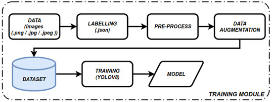
Figure 6.
Implementation steps of YOLOV8 algorithm.
Figure 6 illustrates the stages of the data training process. The first stage is data collection, where 93 different images are captured from various angles in the simulation environment. After completing the data collection phase, the labelling phase begins. Data labelling involves adding specific labels or tags to the data required for training machine learning and artificial intelligence models, facilitating the correct identification and classification of objects or features within the dataset. The labelling process was performed using the AnyLabeling program [29]. Within the environment, 6 different objects were labelled: battery top, battery module, leaf cell, plate, cable, and screw. Data processing for the images and data augmentation were performed to improve the generalization capabilities of the model. Operations including rotation, flipping, cuts, and brightness changes were performed on the images. In this study, we utilized the RoboFlow annotation tool [30]. The training and testing phases are crucial in the development and evaluation of the object detection model. In the training phase, the model was trained using our labelled dataset, and the parameters required for object detection were set. The model was then tested in the simulated environment.
The training of the model occurred on a system equipped with the Ubuntu 20.04LTS OS, an Intel Core i7-13700H CPU, an NVIDIA GeForce RTX 3050 GPU, and an Intel(R) Iris(R) Xe GPU. The Google Colab notebook used for the training process was combined with Jupyter Notebooks to train the model. The image size is set to 640, as it significantly impacts processing speed and memory usage. In addition, image size can negatively affect the detection of small objects in large images. The epoch value is set to 60, indicating that the training dataset is processed 60 times by the model. The training phase was conducted using a Google Colab notebook. In the training phase, the pre-labelled dataset was loaded into the Colab notebook, and the YOLO model was trained while importing the necessary libraries. After model training, it was exported as a benchmark model for object detection, ready to make inferences about items of interest.
4.2. Motion Planning
As can be seen in Figure 5, two different robots sharing the same workspace, Kinect cameras, and a battery pack with objects of different shapes and properties were used in the simulation environment. MoveIt has some features to manage the operation of multiple robots and avoid conflicts, such as robots avoiding collisions with their parts and setting boundaries for robots in multi-robot work. To minimize the risk of collisions due to the robots sharing the same workspace, both robots were considered as a single integrated system, and a single MoveIt file was created. Additionally, in multi-robot scenarios, MoveIt enhances movement control and minimizes conflicts by accurately identifying specific move groups and links associated with each robot. As a result, this approach ensures that both robots perform their tasks smoothly and without interference, effectively managing collision risks and improving system performance.
The maximum working area of each robot extends up to 1300 mm from the base joint, with the recommended area being 85% of this value [31]. The distance between robots is set at 1120 mm. To prevent the robots from colliding or attempting to retrieve objects no longer present in the environment, the visual information of the objects is updated at a camera refresh rate of 8 fps before the robots commence their next movement. Additionally, with multiple robots, the physical workspace is not the only limitation; it has been observed that both robots’ cameras have blind spots, preventing them from seeing the entire working area without some movement. These blind spots and limited working areas present challenges that neither robot can easily solve alone. Cooperation between the two robots is required to overcome these challenges. As a result of this collaboration, the robots can access a more comprehensive workspace and tackle more complex tasks when working together.
Considering the difficulty of using 2–3-finger grippers due to the different sizes and shapes of the objects in the environment, the VG10 vacuum gripper was preferred. In addition, since the estimated positions of the objects are used, the grasping success of the vacuum gripper is higher. Dynamic joints and contact sensors were used to simulate the grasping action for the bolts, and the assumption that these were unbolted beforehand was made. When the robot reaches the object’s position, it makes contact and lifts the object with the vacuum gripper.
After image acquisition commences, the vision system is activated, and all the steps outlined in the previous section are sequentially executed. The coordinate information obtained from the image is then transmitted to the robots. As depicted in Figure 7a, the battery pack model cover initially appears in the experimental environment. Consequently, the robot UR10_1 first grasps the object labelled “battery_top” and initiates motion planning to the sorting position (Figure 7b). While UR10_1 moves towards the target point of the battery case, UR10_2 maintains its position.
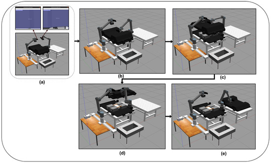
Figure 7.
Removing the battery pack top cover with UR10_1. (a) The object labelled battery_top is detected by the vision algorithm. (b) The UR10_1 robot moves to remove the detected object, (c) picks up the object, (d) moves the object to the drop location, and (e) places the object at the targeted point.
After the removal and placing of the battery case, the UR10_1 robot returns to its home position, while the UR10_2 robot moves to the next object position, picking up the closest and first-priority object, which, in the first case, is the screw, according to the image from the environment (Figure 8a). Upon contact with the screw, the vacuum gripper securely grasps the object. Next, the object is successfully transported to the drop location without being released from the gripper. The UR10_2 robot then transports the gripped object to the drop location, while the UR10_1 robot returns to its home position (Figure 8c).
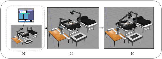
Figure 8.
Removing the screw with UR10_2. (a) The object labelled screw is detected by the vision algorithm. (b) The UR10_2 robot picks up the detected object and (c) places the object at the targeted point.
Then, when the UR10_2 robot arrives at the drop location, the object attached to the gripper is detached, and the robot returns to its home position. Simultaneously, the UR10_1 robot begins moving according to the dynamic object list and reaches the position of the next object in the list (Figure 9a). When the robot contacts the screw and the contact is detected, the object is grasped (Figure 9b). When the UR10_1 robot moves to the drop location, the UR10_2 robot returns to the home position (Figure 9c). At this stage, the UR10_1 robot is at the drop location, and the UR10_2 robot is at the home position in the workspace. After this stage, when UR10_1 reaches the drop location, the object and the gripper are separated from each other. This process continues iteratively, and although both robots work together simultaneously, the risk of collision is minimal. Once all the screws have been removed, the simulation advances to the second stage, which involves collecting cables. Since the screws are no longer securing the cables, the cables are easier to collect. The plate, battery module, and leaf cells all follow the same process stages. Although the present object detection system can properly detect all objects and their placements, screws showed a lower accuracy at being detected than the larger objects.
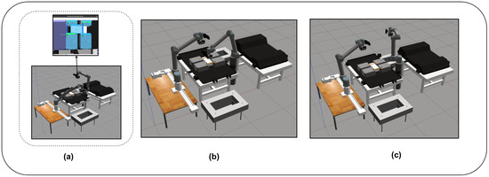
Figure 9.
Removing the screw with UR10_1. (a) The object labelled screw is detected by the vision algorithm. (b) The UR10_1 robot picks up the detected object and (c) places the object at the targeted point.
5. Results and Discussion
In this section, a detailed evaluation of the object segmentation and robot motion-planning processes performed in a simulation environment is presented. The proposed framework is designed to offer flexibility and adjustability to accommodate diverse research requirements. The battery model, robot model, vision algorithm, and planning and control algorithm can be modified as required. Users have the flexibility to tailor components according to their specific needs by following the methodologies outlined in this paper.
5.1. Results of Object Segmentation
After training, various metrics were obtained to evaluate the performance of the model, including the F1 score, precision–recall curve, and class-wise accuracy.
Figure 10a shows that the performance of the model improves as the confidence level increases, particularly demonstrating good results at low confidence thresholds. The shape of the curve suggests that it may be advantageous to run the model at lower confidence levels, especially in scenarios requiring high precision (i.e., minimizing missed true positives). However, using lower confidence thresholds may increase false positives, meaning that the model may incorrectly identify objects that are not present.
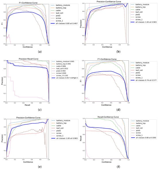
Figure 10.
Performance metrics of the trained model. (a) BoxF1 Curve. (b) BoxP Curve. (c) BoxPR Curve. (d) MaskF1 Curve. (e) MaskP Curve. (f) MaskR Curve.
Figure 10c shows that the recall value is close to 1, whereas the precision value is significantly lower. This demonstrates that the model effectively identifies true positives (correct predictions) but also generates a high number of false positives (incorrect predictions). Thus, the model reliably detects objects, minimizing misses, but tends to yield false alarms due to redundant or erroneous predictions. This indicates strong recall performance but highlights a need for precision enhancement.
Through the process of training the data, the model learns to correctly detect and classify objects. The training results are shown in Figure 11. When running object detection, the vision system equipped with YOLOV8 takes a total of 36.02 s to detect and localize all objects in the scene during the initial startup procedure. Subsequent updates to the items occur at an average rate of 8 fps.
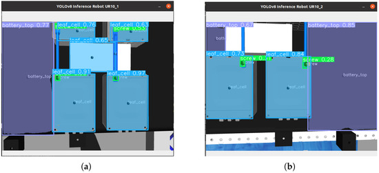
Figure 11.
YOLOV8 output results taken from two different cameras in the simulation environment. (a) The result of the image taken from the camera attached to UR10_1; (b) the result of the image taken from the camera attached to UR10_2.
5.2. Examining Task Planner Performance
In this section, the performance of the task planner in a simulation environment is evaluated by comparing different planners present in MoveIt. RRT, RRTConnect, and RRTStar planners were preferred in the process of testing the proposed task planner in the simulation environment. Pre-planning algorithms rely on full knowledge of the environment model to predetermine a course of action. This speeds up the planning process but may fail in practice due to model errors or changing conditions. However, instance-based algorithms, such as RRT, make instantaneous decisions and adaptively respond to uncertainties. In these algorithms, the environment is explored by taking random samples at each step, and the process of determining the course of action proceeds in real time. The scalability and effectiveness of the selected algorithms in operating successfully in complex, changing environments were key factors in their selection. All three planners have various advantages and disadvantages. Although the RRT planner can be easily applied to different kinematic and dynamic robot models and has the advantage of being fast in environment exploration, it does not guarantee optimality, meaning it does not guarantee that the paths found are optimal. Only RRTStar guarantees optimal solutions based on the defined optimization objective. This is why RRTStar usually takes the longest planning time. On the other hand, RRTConnect guarantees a solution (asymptotic solution) since it grows two RRT trees, one from the start and one from the target, in the configuration space of the robot. In this study, battery component disassembly was performed using these planners, enabling the robots to successfully plan trajectories for tasks, even when the constraints of these trajectories were complex due to the positioning of other robots. These trajectory planners are among the most widely used and easily accessible within MoveIt. Nevertheless, any other trajectory planners could be used with our task planner, as these are merely the means to reach a position. The crucial aspect of task completion is more dependent on our task planner framework. The obtained results are given in Table 1. In the table, the names of the objects used in the experimental environment and the robot carrying out the operation are also provided.

Table 1.
Comparison of battery removal times when using two robots together according to three different planners.
As observed in Table 1, there are no significant performance differences between the completion processes of the disassembly process using the RRT, RRTConnect, and RRTStar planners. However, the disassembly process using the RRTConnect planner was faster than with the RRT and RRTStar planners. It is important to note that the vision algorithm experienced some slowdowns due to computational limitations in the simulations, and due to this, only the disassembly process times were recorded.
While disassembling the objects, the length of the trajectory followed by the robots during the disassembly process was calculated using different planners. As seen in Table 2, the differences between the path lengths are quite small. When we look at the total distances tracked on a robot basis, Robot 1 completed the tasks in the shortest distance when using the RRT planner, while the distance increased from 3528.66 to 3532.93 when performing the same process using the RRTStar planner. For the second robot, this was the opposite. While the total distance tracked using the RRT planner was 3397.33, the distance tracked using the RRTStar planner was 3384.68. It is important to note that these variations are not significant and can be due to the detection of different centre positions in the vision algorithm.

Table 2.
Comparison of path length when using two robots together according to three different planners.
Graphs of the trajectories followed for six randomly selected objects are given in Figure 12. According to these graphs, although it is observed that similar trajectories are produced by the three different planners during the disassembly of objects, there are small differences in the paths. The differences in the trajectories produced by the three different planners are due to changes in the pixel values of the coordinates detected by the robots. These changes occur when each planner calculates a different motion path and, as a result, receives the robot’s physical position and goal differently.
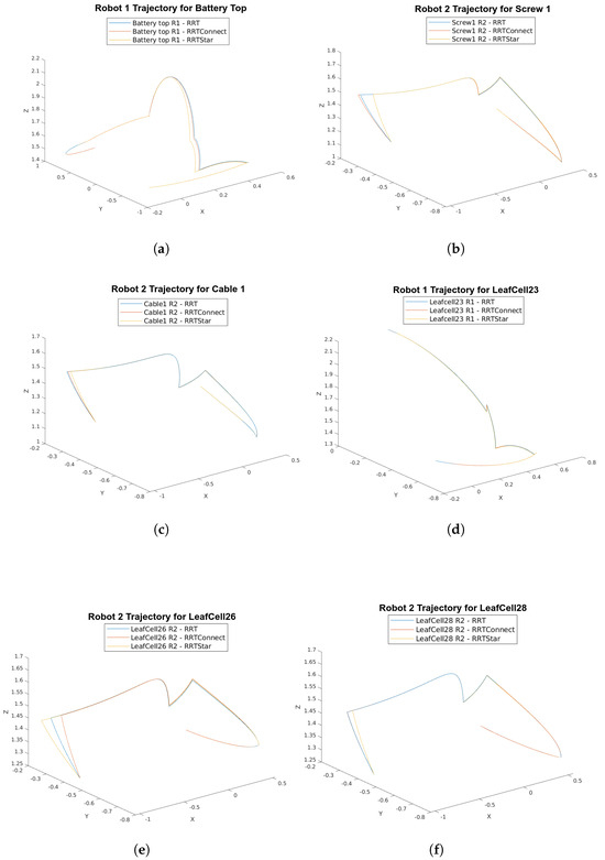
Figure 12.
Trajectory graphs followed by robots during the disassembly process of randomly selected objects using the RRT, RRTConnect, and RRTStar planners. (a–f) Trajectories followed by robots during the disassembly of objects called battery_top, screw1, cable1, leafcell23, leafcell26, and leafcell28, respectively.
This paper has met its stated goals. It integrates multiple research areas, such as computer vision, robotics, task planning, and the disassembly of battery packs, which were successfully performed and compared across planners. The primary hardware elements, including an industrial robot, a 3D camera, and a vacuum gripper, have been interconnected to carry out fundamental system tasks such as object detection, pose estimation, decision-making, and component sorting. Consequently, the system can recognize the essential components of the objects slated for disassembly, accurately locate them, and guide the robots to their designated positions in a dynamically defined sequence. A feature of the enhanced task planner is the advantage gained from using more than one robot. This feature enables one robot to access areas that another cannot reach or that are considered blind spots. Thus, trajectory planning is performed more efficiently, and the capabilities of each robot are maximized. Additionally, using multiple robots increases the speed of the dismantling process, allowing it to be completed more quickly. Simulation experiments were conducted to assess the performance and precision of the developed task planner. While the investigations were focused on the NISSAN e-NV200 pack, the approach is adaptable to any EV battery pack. Furthermore, the proposed task planner can be used to be effective not only in battery disassembly but also in dismantling various other objects, utilizing the YOLOV8 vision algorithm as demonstrated for dynamic planning and the disassembly of other objects.
6. Conclusions
In this paper, a comprehensive task planner for multi-robot battery recycling is presented. The vision, planning, and control algorithms proposed in this task planner are detailed. The performance of the proposed task planner was evaluated in a simulation environment using RRT, RRTConnect, and RRTStar planners. As the main components of the simulated hardware system, an overall EV battery pack consisting of 16 leaf cells (grouped into quads) with interconnected screws and cables and a Kinect RGB-D camera connected to the robot’s end-effector were integrated into the environment. For the simulation environment, CAD models of the battery pack and its components were imported into Gazebo for object interactions. In this simulation environment, the two robots started disassembly operations in a synchronized manner according to the information from the camera and completed the disassembly process without collision. Our logical planner has been demonstrated to be planning-algorithm-agnostic, with an average of 544.07 s and a mean of 3530.89 (UR10_1) and 3391.77 cm (UR10_2) travelled for the completion of our proposed task across the different trajectory planners. The standard deviation between the trajectory planners was only 2.31 s, with standard deviations of 1.75 cm and 5.28 cm across the planners, respectively. The minor variations in time and travelled distance do not affect the effectiveness of the logical task planner, which successfully adapted to the task regardless of the trajectory planner. The number of robots and objects used in the simulation environment in this paper can be extended, and the proposed task planner can be used not only for battery disassembly but also for the disassembly of any object. The adaptive structure of the proposed logic task planner offers the ability to easily adapt to different objects and avoid collisions in multi-robot use. Although only two robots were used in this study, the number of robots can easily be increased and adapted to different disassembly processes in future studies. In future studies, we will aim to obtain more concrete results by modelling the interaction of the experimental environment created in the Gazebo environment with real objects in the real environment. We will also address some of the limitations, including the processing time of the object detection algorithm, by reducing the calculated frames per second (FPS) and increasing the training data to improve speed and reliability. Additionally, we will tackle camera space limitations by enabling the robots to navigate through the scene in advance to capture positions that are not normally visible. Environmental collisions will be addressed by integrating the scene’s point cloud.
Author Contributions
Conceptualization, A.R.; methodology, C.E.; software, C.E. and C.A.C.; validation, C.E., C.A.C. and A.R.; investigation, C.E., C.A.C. and A.R.; data curation, C.E. and C.A.C.; writing—original draft preparation, C.E., C.A.C. and A.R.; writing—review and editing, C.E., C.A.C. and A.R.; visualization, C.E.; supervision, A.R. and R.S.; project administration, A.R.; funding acquisition, A.R. and R.S. All authors have read and agreed to the published version of the manuscript.
Funding
This work was funded by the project called “Research and Development of a Highly Automated and Safe Streamlined Process for Increase Lithium-ion Battery Repurposing and Recycling” (REBELION) under Grant 101104241 and partially supported by the Ministry of National Education, Republic of Turkey.
Data Availability Statement
The data presented in this study are available on request from the corresponding author.
Acknowledgments
The authors would like to thank Mohammed Eesa Asif for his support.
Conflicts of Interest
The authors declare no conflicts of interest.
References
- Jacoby, M. It’s time to get serious about recycling lithium-ion batteries. Chem. Eng. News 2019, 97, 29–32. [Google Scholar]
- Islam, M.T.; Iyer-Raniga, U. Lithium-Ion Battery Recycling in the Circular Economy: A Review. Recycling 2022, 7, 33. [Google Scholar] [CrossRef]
- Wegener, K.; Andrew, S.; Raatz, A.; Dröder, K.; Herrmann, C. Disassembly of Electric Vehicle Batteries Using the Example of the Audi Q5 Hybrid System. Procedia CIRP 2014, 23, 155–160. [Google Scholar] [CrossRef]
- Wegener, K.; Chen, W.H.; Dietrich, F.; Dröder, K.; Kara, S. Robot Assisted Disassembly for the Recycling of Electric Vehicle Batteries. Procedia CIRP 2015, 29, 716–721. [Google Scholar] [CrossRef]
- Chen, W.H.; Wegener, K.; Dietrich, F. A robot assistant for unscrewing in hybrid human-robot disassembly. In Proceedings of the 2014 IEEE International Conference on Robotics and Biomimetics (ROBIO 2014), Bali, Indonesia, 5–10 December 2014; pp. 536–541. [Google Scholar] [CrossRef]
- Kristensen, C.B.; Sørensen, F.A.; Nielsen, H.B.; Andersen, M.S.; Bendtsen, S.P.; Bøgh, S. Towards a Robot Simulation Framework for E-waste Disassembly Using Reinforcement Learning. Procedia Manuf. 2019, 38, 225–232. [Google Scholar] [CrossRef]
- Peng, Y.; Li, W.; Liang, Y.; Pham, D.T. Robotic disassembly of screws for end-of-life product remanufacturing enabled by deep reinforcement learning. J. Clean. Prod. 2024, 439, 140863. [Google Scholar] [CrossRef]
- Torres, F.; Puente, S.; Díaz, C. Automatic cooperative disassembly robotic system: Task planner to distribute tasks among robots. Control Eng. Pract. 2009, 17, 112–121. [Google Scholar] [CrossRef]
- Fernandez, C.; Reinoso, O.; Vicente, M.; Aracil, R. Part grasping for automated disassembly. Int. J. Adv. Manuf. Technol. 2006, 30, 540–553. [Google Scholar] [CrossRef]
- Kay, I.; Farhad, S.; Mahajan, A.; Esmaeeli, R.; Hashemi, S.R. Robotic Disassembly of Electric Vehicles’ Battery Modules for Recycling. Energies 2022, 15, 4856. [Google Scholar] [CrossRef]
- Choux, M.; Marti Bigorra, E.; Tyapin, I. Task Planner for Robotic Disassembly of Electric Vehicle Battery Pack. Metals 2021, 11, 387. [Google Scholar] [CrossRef]
- Wang, H.; Zhang, K.; Zhu, K.; Song, Z.; Li, Z. ABatRe-Sim: A Comprehensive Framework for Automated Battery Recycling Simulation. In Proceedings of the 2023 IEEE International Conference on Robotics and Biomimetics (ROBIO), Samui, Thailand, 4–9 December 2023; pp. 1–8. [Google Scholar]
- Hathaway, J.; Contreras, C.A.; Asif, M.E.; Stolkin, R.; Rastegarpanah, A. Technoeconomic Assessment of Electric Vehicle Battery Disassembly—Challenges and Opportunities from a Robotics Perspective. Preprint 2024. [Google Scholar] [CrossRef]
- Gazebo Robotics Simulator. 2022. Available online: http://gazebosim.org/ (accessed on 27 February 2024).
- Rastegarpanah, A.; Gonzalez, H.C.; Stolkin, R. Semi-Autonomous Behaviour Tree-Based Framework for Sorting Electric Vehicle Batteries Components. Robotics 2021, 10, 82. [Google Scholar] [CrossRef]
- Hathaway, J.; Shaarawy, A.; Akdeniz, C.; Aflakian, A.; Stolkin, R.; Rastegarpanah, A. Towards reuse and recycling of lithium-ion batteries: Tele-robotics for disassembly of electric vehicle batteries. Front. Robot. AI 2023, 10, 1179296. [Google Scholar] [CrossRef] [PubMed]
- Mironov, D.; Altamirano, M.; Zabihifar, H.; Liviniuk, A.; Liviniuk, V.; Tsetserukou, D. Haptics of Screwing and Unscrewing for its Application in Smart Factories for Disassembly. arXiv 2018, arXiv:1801.10386. [Google Scholar]
- Palleschi, A.; Pollayil, G.J.; Pollayil, M.J.; Garabini, M.; Pallottino, L. High-Level Planning for Object Manipulation With Multi Heterogeneous Robots in Shared Environments. IEEE Robot. Autom. Lett. 2022, 7, 3138–3145. [Google Scholar] [CrossRef]
- Pan, T.; Wells, A.M.; Shome, R.; Kavraki, L.E. A General Task and Motion Planning Framework For Multiple Manipulators. In Proceedings of the 2021 IEEE/RSJ International Conference on Intelligent Robots and Systems (IROS), Prague, Czech Republic, 27 September–1 October 2021; pp. 3168–3174. [Google Scholar] [CrossRef]
- Zhu, X.; Xu, J.; Ge, J.; Wang, Y.; Xie, Z. Multi-Task Multi-Agent Reinforcement Learning for Real-Time Scheduling of a Dual-Resource Flexible Job Shop with Robots. Processes 2023, 11, 267. [Google Scholar] [CrossRef]
- Touzani, H.; Séguy, N.; Hadj-Abdelkader, H.; Suárez, R.; Rosell, J.; Palomo-Avellaneda, L.; Bouchafa, S. Efficient Industrial Solution for Robotic Task Sequencing Problem With Mutual Collision Avoidance & Cycle Time Optimization. IEEE Robot. Autom. Lett. 2022, 7, 2597–2604. [Google Scholar] [CrossRef]
- Chen, H.; Wan, W.; Koyama, K.; Harada, K. Planning to Build Block Structures With Unstable Intermediate States Using Two Manipulators. IEEE Trans. Autom. Sci. Eng. 2022, 19, 3777–3793. [Google Scholar] [CrossRef]
- Fleischer, J.; Gerlitz, E.; RieB, S.; Coutandin, S.; Hofmann, J. Concepts and Requirements for Flexible Disassembly Systems for Drive Train Components of Electric Vehicles. Procedia CIRP 2021, 98, 577–582. [Google Scholar] [CrossRef]
- Cáceres Domínguez, D.; Iannotta, M.; Stork, J.A.; Schaffernicht, E.; Stoyanov, T. A Stack-of-Tasks Approach Combined With Behavior Trees: A New Framework for Robot Control. IEEE Robot. Autom. Lett. 2022, 7, 12110–12117. [Google Scholar] [CrossRef]
- Safronov, E.; Colledanchise, M.; Natale, L. Task Planning with Belief Behavior Trees. arXiv 2020, arXiv:2008.09393. [Google Scholar]
- Jacob Solawetz, F. What Is YOLOv8? The Ultimate Guide. 2024. Available online: https://blog.roboflow.com/whats-new-in-yolov8/ (accessed on 29 February 2024).
- Rastegarpanah, A.; Hathaway, J.; Stolkin, R. Vision-Guided MPC for Robotic Path Following Using Learned Memory-Augmented Model. Front. Robot. AI 2021, 8, 688275. [Google Scholar] [CrossRef] [PubMed]
- Coleman, D.; Sucan, I.A.; Chitta, S.; Correll, N. Reducing the Barrier to Entry of Complex Robotic Software: A MoveIt! Case Study. arXiv 2014, arXiv:1404.3785. [Google Scholar]
- AnyLabeling: Effortless Data Labeling. 2024. Available online: https://anylabeling.com (accessed on 5 January 2024).
- RoboFlow. Roboflow: Give Your Software the Sense of Sight. 2024. Available online: https://roboflow.com/ (accessed on 5 January 2024).
- Universal Robots. Universal Robots User Manual. PDF. Available online: https://s3-eu-west-1.amazonaws.com/ur-support-site/41240/UR10e_User_Manual_en_US.pdf (accessed on 29 April 2024).
Disclaimer/Publisher’s Note: The statements, opinions and data contained in all publications are solely those of the individual author(s) and contributor(s) and not of MDPI and/or the editor(s). MDPI and/or the editor(s) disclaim responsibility for any injury to people or property resulting from any ideas, methods, instructions or products referred to in the content. |
© 2024 by the authors. Licensee MDPI, Basel, Switzerland. This article is an open access article distributed under the terms and conditions of the Creative Commons Attribution (CC BY) license (https://creativecommons.org/licenses/by/4.0/).