
NU-Biped-4.5: A Lightweight and Low-Prototyping-Cost Full-Size Bipedal Robot


Abstract
:1. Introduction

- Lightweight design: The robot, which is 1.1 m tall and equipped with 12 DOFs, falls into the category of full-size bipedal humanoid robots, yet weighs only 15 kg (without considering the battery). This was possible by using lightweight materials and customized, in-house-developed, high-power-to-weight-ratio servomotors.
- Low-cost prototyping: The total cost for materials, actuators, sensors, and the computational board is under USD 5000.
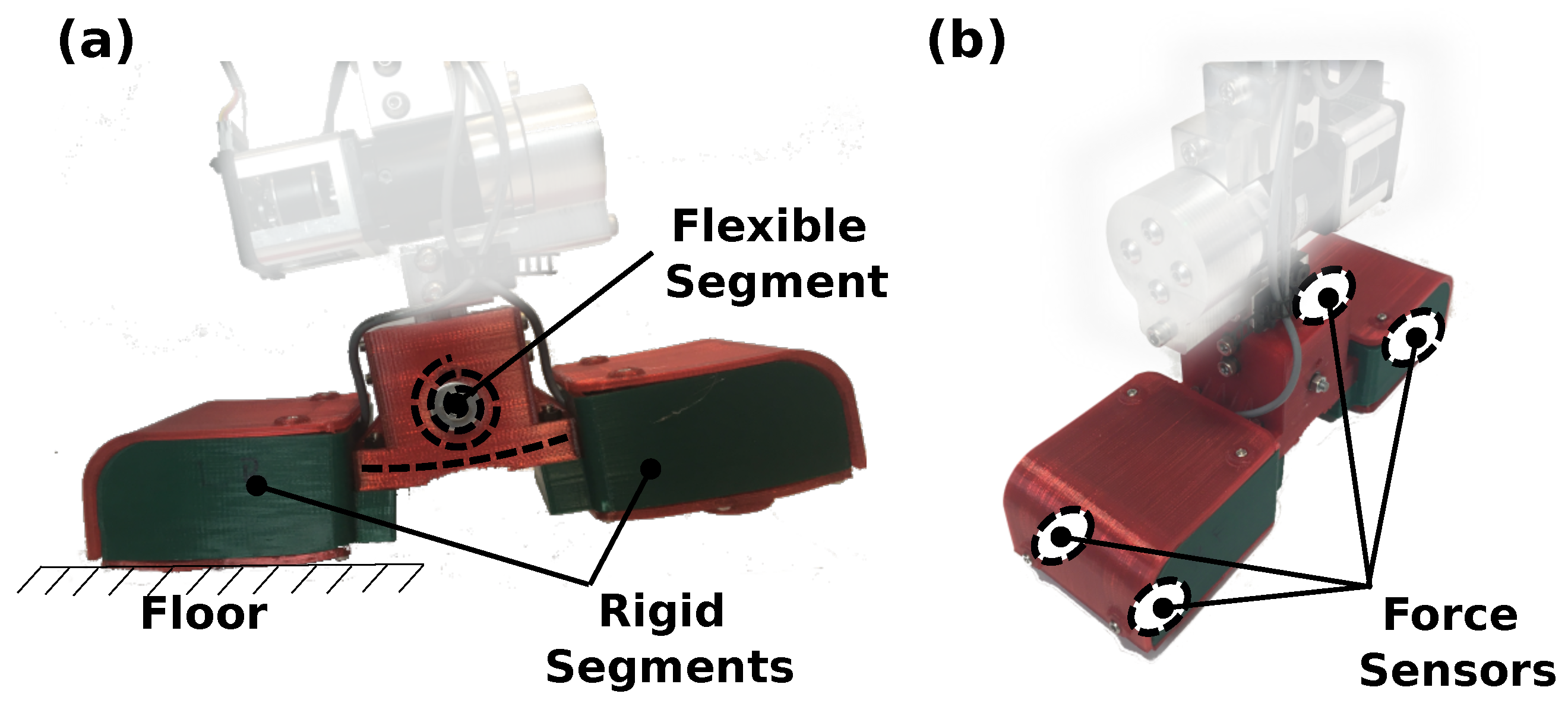
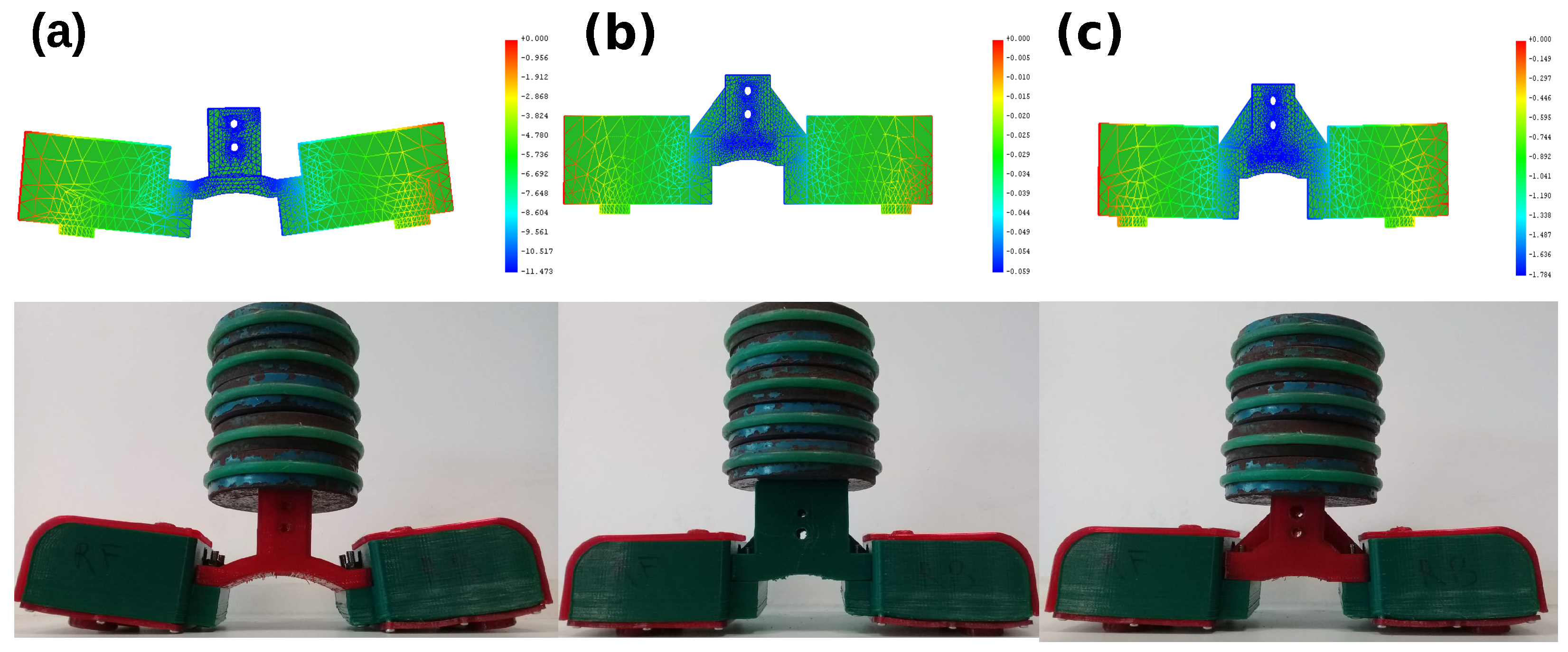
- Optimized ankle design: The robot’s feet feature a central elastic element designed to dampen impact forces and store and release potential energy throughout the gait.
- Low Energy consumption and safe operation are achieved due to the lightweight and low inertial properties of the robot’s links.
2. Robot Architecture and Design
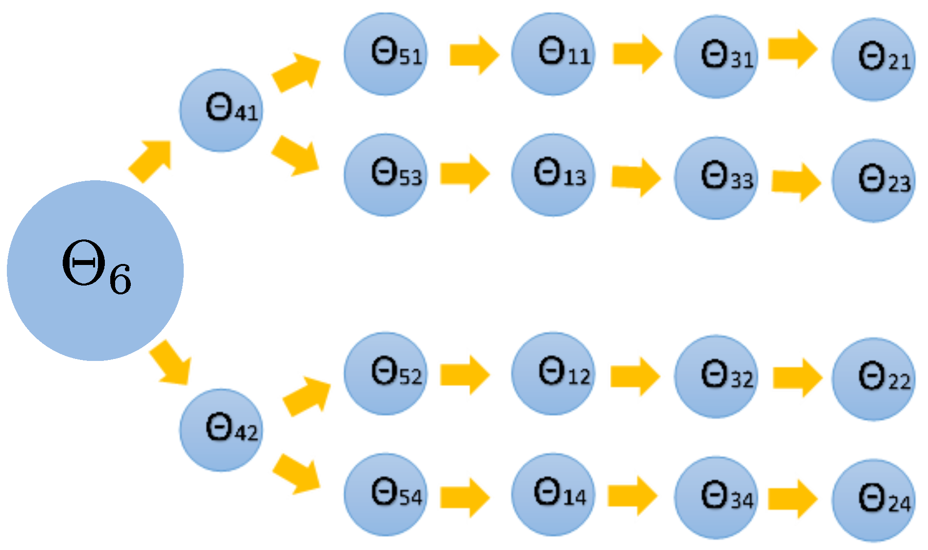
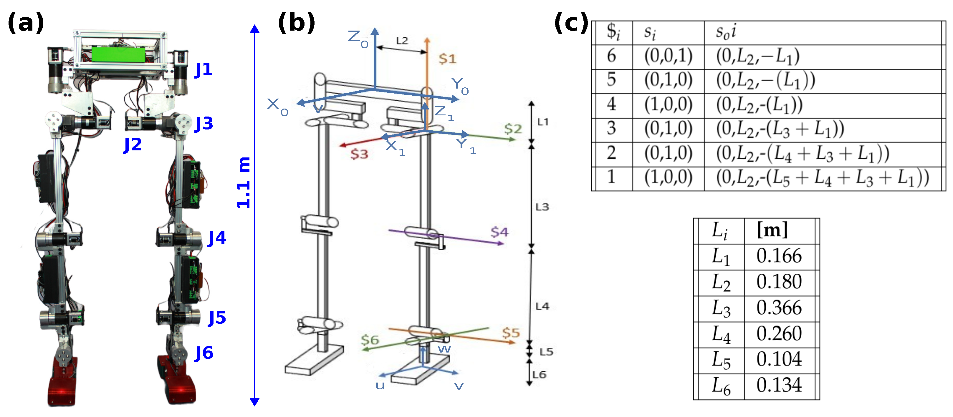
2.1. Kinematic Model
2.2. Mechanical and Electrical Design
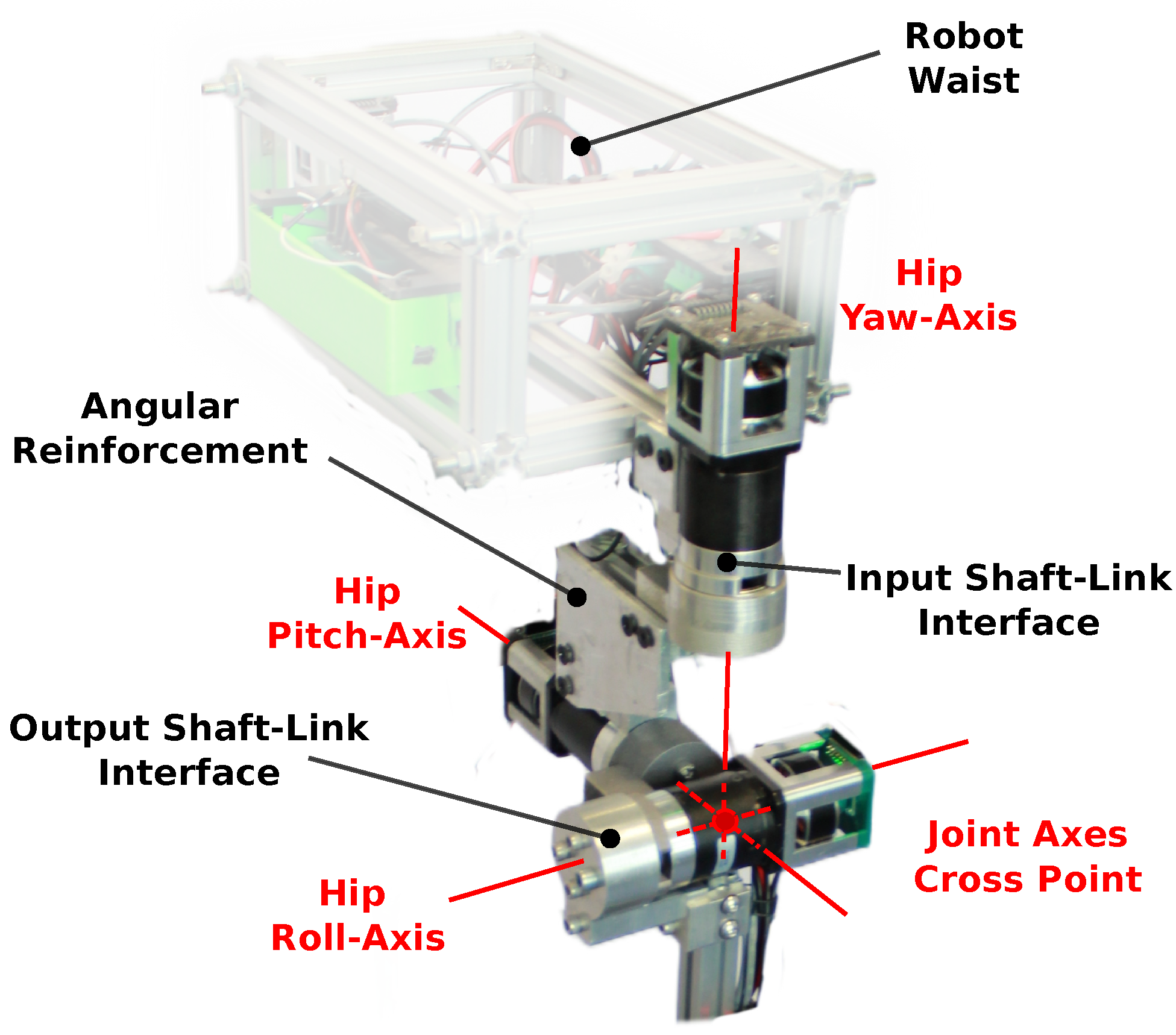
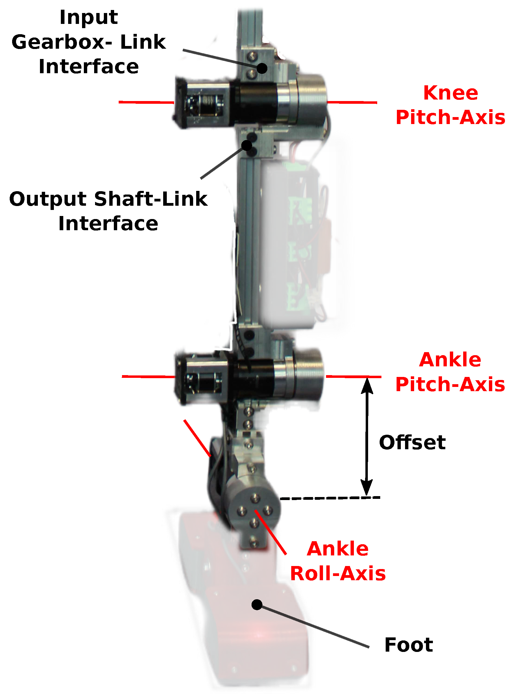
2.2.1. Mechanical Design
2.2.2. Electrical Design
2.2.3. Actuation System Design
3. Validation and Testing of the Bipedal Robot
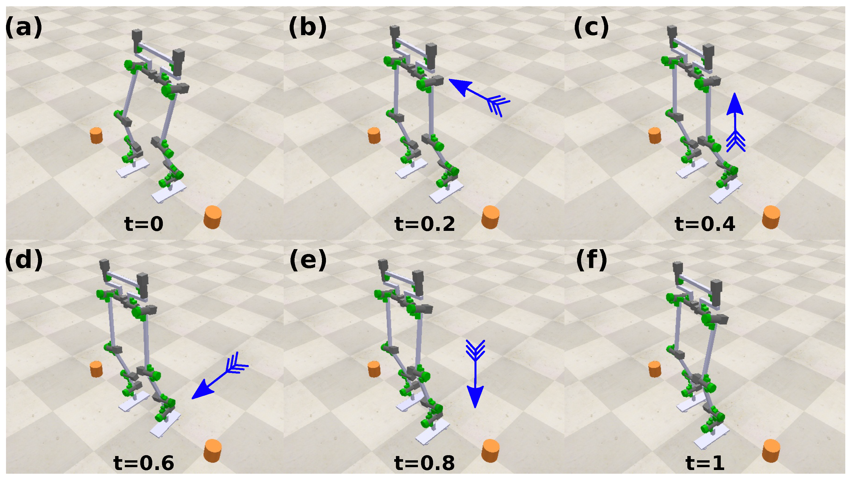
3.1. Simulation Environment
3.2. Prototype Test
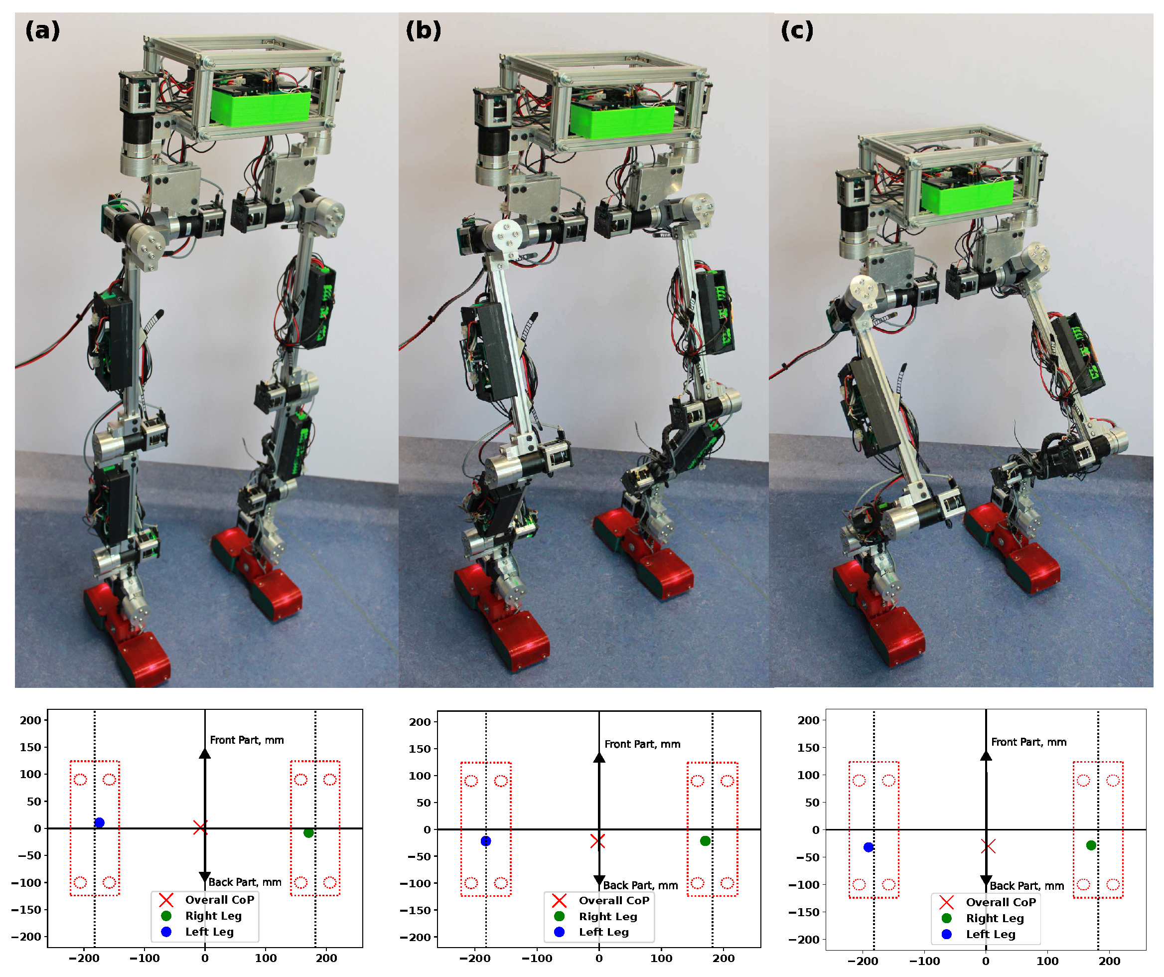
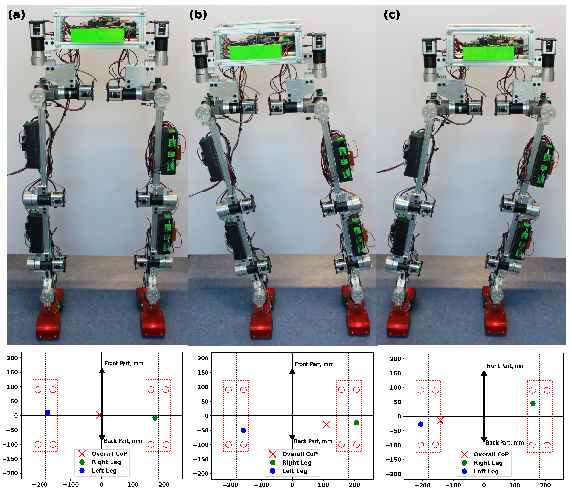
3.2.1. Lateral and Squat Motion
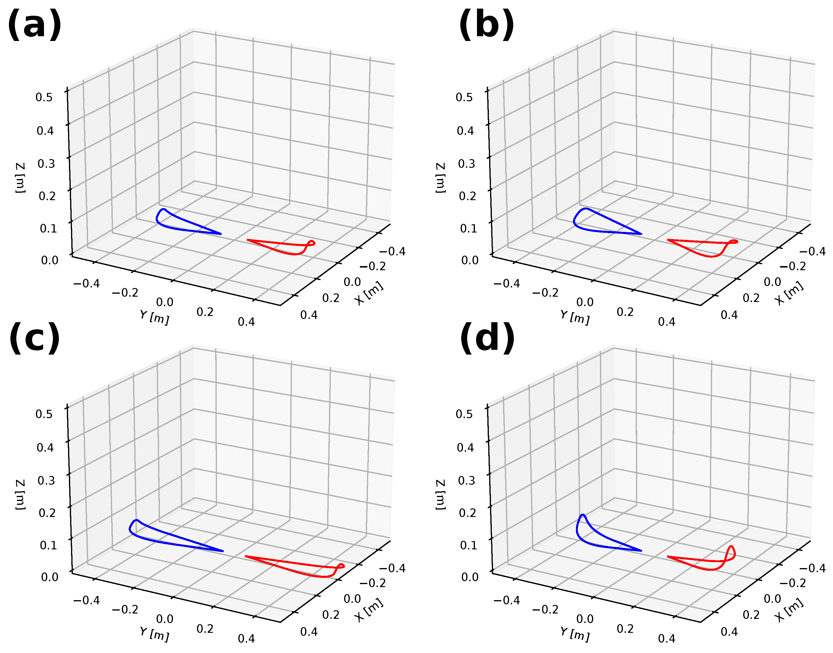
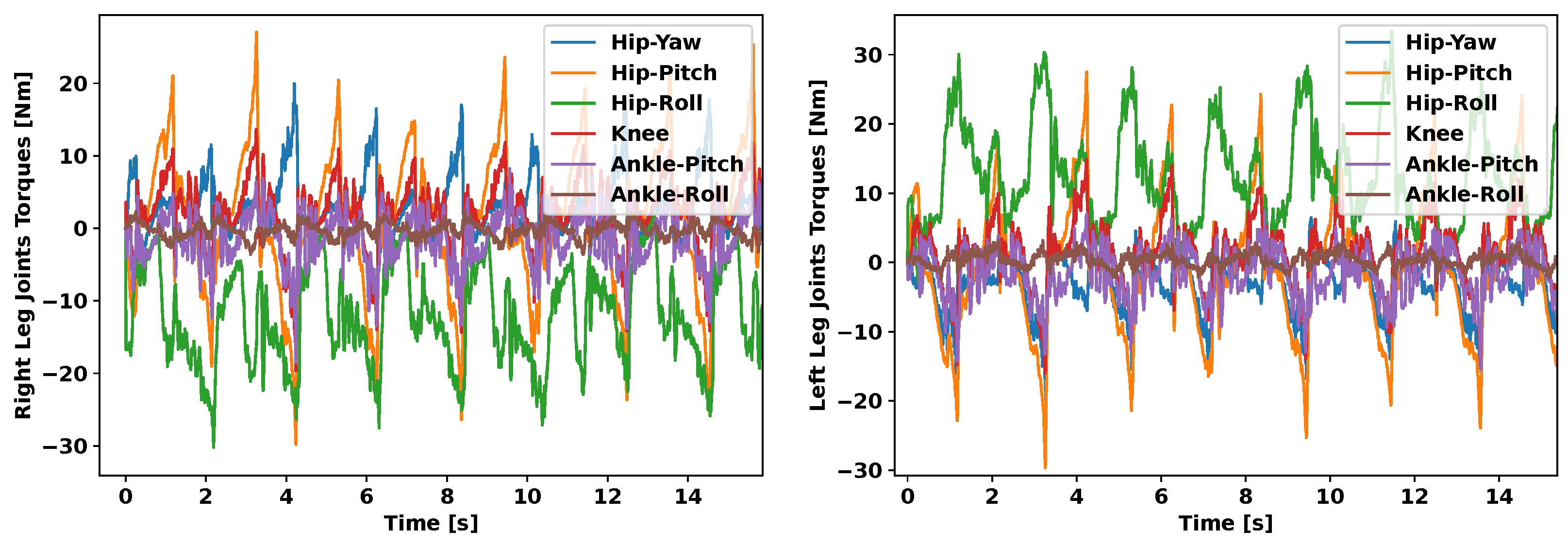
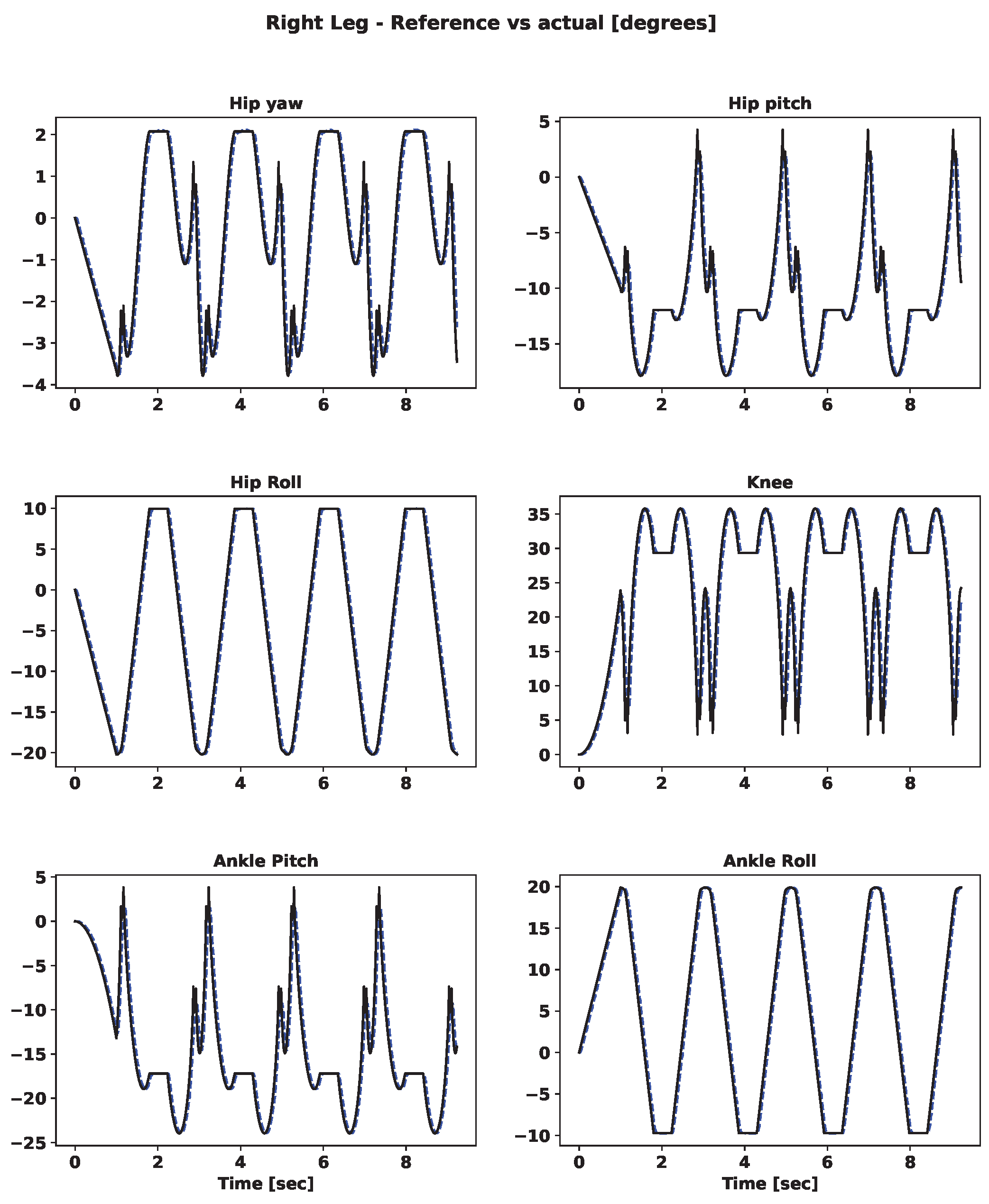
3.2.2. Gait Sequence
4. Discussion
5. Conclusions
Author Contributions
Funding
Data Availability Statement
Conflicts of Interest
Abbreviations
| DOF | Degree of freedom |
| COM | Center of mass |
| COP | Center of pressure |
| FK | Forward kinematics |
| IK | Inverse kinematics |
| IMU | Inertial measurement unit |
| BLDC | Direct current brushless |
| PLA | Polylactide |
| TPU | Thermoplastic Polyurethane |
| PCB | Printed circuit board |
| PID | Proportional integral derivative |
| AGI | Artificial general intelligence |
| FEA | Finite element analysis |
| FSR | Force-sensitive resistor |
| SEA | Serial elastic actuator |
| PEA | Parallel elastic actuator |
| VSA | Variable stiffness actuator |
| LWR | Lightweight robot |
| CNC | Computer numerical control |
| ZMP | Zero-moment point |
Appendix A
References
- Ogura, Y.; Aikawa, H.; Shimomura, K.; Kondo, H.; Morishima, A.; ok Lim, H.; Takanishi, A. Development of a new humanoid robot WABIAN-2. In Proceedings of the Proceedings 2006 IEEE International Conference on Robotics and Automation, ICRA 2006, Orlando, FL, USA, 15–19 May 2006; pp. 76–81. [Google Scholar] [CrossRef]
- Kaneko, K.; Kanehiro, F.; Morisawa, M.; Akachi, K.; Miyamori, G.; Hayashi, A.; Kanehira, N. Humanoid robot HRP-4—Humanoid robotics platform with lightweight and slim body. In Proceedings of the 2011 IEEE/RSJ International Conference on Intelligent Robots and Systems, San Francisco, CA, USA, 25–30 September 2011; pp. 4400–4407. [Google Scholar] [CrossRef]
- Kaneko, K.; Kaminaga, H.; Sakaguchi, T.; Kajita, S.; Morisawa, M.; Kumagai, I.; Kanehiro, F. Humanoid Robot HRP-5P: An Electrically Actuated Humanoid Robot with High-Power and Wide-Range Joints. IEEE Robot. Autom. Lett. 2019, 4, 1431–1438. [Google Scholar] [CrossRef]
- He, B.; Miao, Q.; Zhou, Y.; Wang, Z.; Li, G.; Xu, S. Review of Bioinspired Vision-Tactile Fusion Perception (VTFP): From Humans to Humanoids. IEEE Trans. Med Robot. Bionics 2022, 4, 875–888. [Google Scholar] [CrossRef]
- Radford, A.; Narasimhan, K.; Salimans, T.; Sutskever, I. Improving Language Understanding by Generative Pre-Training 2018. Available online: https://www.google.com.ua/url?sa=t&rct=j&q=&esrc=s&source=web&cd=&ved=2ahUKEwiVr4Kao6-DAxUtr1YBHVTbAzEQFnoECAoQAQ&url=https%3A%2F%2Fs3-us-west-2.amazonaws.com%2Fopenai-assets%2Fresearch-covers%2Flanguage-unsupervised%2Flanguage_understanding_paper.pdf&usg=AOvVaw2_cln7aRjbG09uzieV6Bv4&opi=89978449 (accessed on 29 December 2023).
- Nakajima, K. Reservoir computing: Theory, physical implementations, and applications. IEICE Tech. Rep. 2018, 118, 149–154. [Google Scholar]
- Asfour, T.; Yokoi, K.; Lee, C.; Kuffner, J. Humanoid Robotics TC Spotlight. IEEE Robot. Autom. Mag. 2012, 19, 108–118. [Google Scholar] [CrossRef]
- Saeedvand, S.; Jafari, M.; Aghdasi, H.S.; Baltes, J. A comprehensive survey on humanoid robot development. Knowl. Eng. Rev. 2019, 34, e20. [Google Scholar] [CrossRef]
- Boston Dynamics, Atlas Humanoid Robot. Available online: https://www.bostondynamics.com/atlas (accessed on 29 December 2023).
- Kuindersma, S.; Deits, R.; Fallon, M.; Valenzuela, A.; Dai, H.; Permenter, F.; Koolen, T.; Marion, P.; Tedrake, R. Optimization-based locomotion planning, estimation, and control design for the atlas humanoid robot. Auton. Robot. 2015, 40, 429–455. [Google Scholar] [CrossRef]
- Lohmeier, S.; Buschmann, T.; Ulbrich, H. Humanoid robot LOLA. In Proceedings of the 2009 IEEE International Conference on Robotics and Automation, Kobe, Japan, 12–17 May 2009; pp. 775–780. [Google Scholar] [CrossRef]
- Pratt, J.E.; Pratt, G.A. Exploiting Natural Dynamics in the Control of a 3 D Bipedal Walking Simulation. In Proceedings of the International Conference on Climbing and Walking Robots (CLAWAR99), Portsmouth, UK, September 1999. [Google Scholar]
- Asano, Y.; Kozuki, T.; Ookubo, S.; Kawamura, M.; Nakashima, S.; Katayama, T.; Yanokura, I.; Hirose, T.; Kawaharazuka, K.; Makino, S.; et al. Human mimetic musculoskeletal humanoid Kengoro toward real world physically interactive actions. In Proceedings of the 2016 IEEE-RAS 16th International Conference on Humanoid Robots (Humanoids), Cancun, Mexico, 15–17 November 2016; pp. 876–883. [Google Scholar] [CrossRef]
- Eßer, J.; Kumar, S.; Peters, H.; Bargsten, V.; Fernández, J.; Mastalli, C.; Stasse, O.; Kirchner, F. Design, analysis and control of the series-parallel hybrid RH5 humanoid robot. In Proceedings of the 2020 IEEE-RAS 20th International Conference on Humanoid Robots (Humanoids), Munich, Germany, 19–21 July 2021; pp. 400–407. [Google Scholar] [CrossRef]
- Folgheraiter, M.; Yskak, A.; Yessirkepov, S. One-Shot Bipedal Robot Dynamics Identification With a Reservoir-Based RNN. IEEE Access 2023, 11, 50180–50194. [Google Scholar] [CrossRef]
- Folgheraiter, M.; Yessirkepov, S.; Umurzakov, T.; Korabay, R. NU-Biped-4 a Lightweight and Low-Power Consumption Full-Size Bipedal Robot. In Proceedings of the 2023 9th International Conference on Automation, Robotics and Applications (ICARA), Abu Dhabi, United Arab Emirates, 10–12 February 2023; pp. 38–43. [Google Scholar] [CrossRef]
- Hyon, S.H.; Suewaka, D.; Torii, Y.; Oku, N. Design and Experimental Evaluation of a Fast Torque-Controlled Hydraulic Humanoid Robot. IEEE/ASME Trans. Mechatronics 2017, 22, 623–634. [Google Scholar] [CrossRef]
- Ude, A.; Atkeson, C. Real-time visual system for interaction with a humanoid robot. In Proceedings of the 2001 IEEE/RSJ International Conference on Intelligent Robots and Systems. Expanding the Societal Role of Robotics in the the Next Millennium (Cat. No.01CH37180), Maui, HI, USA, 29 October–3 November 2001; Volume 2, pp. 746–751. [Google Scholar] [CrossRef]
- Farnioli, E.; Gabiccini, M.; Bicchi, A. Toward whole-body loco-manipulation: Experimental results on multi-contact interaction with the Walk-Man robot. In Proceedings of the 2016 IEEE/RSJ International Conference on Intelligent Robots and Systems (IROS), Daejeon, Republic of Korea, 9–14 October 2016; pp. 1372–1379. [Google Scholar] [CrossRef]
- Tsagarakis, N.; Caldwell, D.G.; Bicchi, A.; Negrello, F.; Garabini, M.; Choi, W.; Baccelliere, L.; Loc, V.G.; Noorden, J.; Catalano, M.; et al. WALK-MAN: A High Performance Humanoid Platform for Realistic Environments. J. Field Robot. 2017, 34, 1225–1259. [Google Scholar] [CrossRef]
- Englsberger, J.; Werner, A.; Ott, C.; Henze, B.; Roa, M.A.; Garofalo, G.; Burger, R.; Beyer, A.; Eiberger, O.; Schmid, K.; et al. Overview of the torque-controlled humanoid robot TORO. In Proceedings of the 2014 14th IEEE-RAS International Conference on Humanoid Robots (Humanoids), Madrid, Spain, 18–20 November 2014; pp. 916–923. [Google Scholar]
- Henze, B.; Dietrich, A.; Ott, C. An Approach to Combine Balancing with Hierarchical Whole-Body Control for Legged Humanoid Robots. IEEE Robot. Autom. Lett. 2016, 1, 700–707. [Google Scholar] [CrossRef]
- Huang, Y.; Li, Q.; Ming, A.; Liu, Y.; Liu, Y.; Huang, Q. Dynamic Gait Transition of a Humanoid Robot from Hand-Knee Crawling to Bipedal Walking based on Kinematic Primitives. In Proceedings of the 2019 IEEE International Conference on Advanced Robotics and its Social Impacts (ARSO), Beijing, China, 31 October–2 November 2019; pp. 240–245. [Google Scholar] [CrossRef]
- Chen, X.; Liao, W.; Yu, Z.; Qi, H.; Jiang, X.; Huang, Q. Motion coordination for humanoid jumping using maximized joint power. Adv. Mech. Eng. 2021, 13, 168781402110284. [Google Scholar] [CrossRef]
- Yu, Z.; Huang, Q.; Ma, G.; Chen, X.; Zhang, W.; Li, J.; Gao, J. Design and development of the humanoid robot BHR-5. Adv. Mech. Eng. 2014, 6, 852937. [Google Scholar] [CrossRef]
- Asfour, T.; Schill, J.; Peters, H.; Klas, C.; Bücker, J.; Sander, C.; Schulz, S.; Kargov, A.; Werner, T.; Bartenbach, V. ARMAR-4: A 63 DOF torque controlled humanoid robot. In Proceedings of the 2013 13th IEEE-RAS International Conference on Humanoid Robots (Humanoids), Atlanta, GA, USA, 15–17 October 2013; pp. 390–396. [Google Scholar] [CrossRef]
- Xiong, X.; Ames, A. 3-D Underactuated Bipedal Walking via H-LIP Based Gait Synthesis and Stepping Stabilization. IEEE Trans. Robot. 2022, 38, 2405–2425. [Google Scholar] [CrossRef]
- Ackerman, E. How Robots Can Help US Act and Feel Younger: Toyota’s Gill Pratt on Enhancing Independence in Old Age. IEEE Spectr. 2022, 59, 26–31. [Google Scholar] [CrossRef]
- Balkibekov, K.; Meiirbekov, S.; Tazhigaliyeva, N.; Sandygulova, A. Should robots win or lose? Robot’s losing playing strategy positively affects child learning. In Proceedings of the IEEE RO-MAN, New York, NY, USA, 26–31 August 2016; pp. 706–711. [Google Scholar]
- Kim, J.; Cauli, N.; Vicente, P.; Damas, B.; Cavallo, F.; Santos-Victor, J. “iCub, clean the table!” A robot learning from demonstration approach using deep neural networks. In Proceedings of the 2018 IEEE International Conference on Autonomous Robot Systems and Competitions (ICARSC), Torres Vedras, Portugal, 25–27 April 2018; pp. 3–9. [Google Scholar] [CrossRef]
- Jung, T.; Lim, J.; Bae, H.; Lee, K.K.; Joe, H.M.; Oh, J.H. Development of the Humanoid Disaster Response Platform DRC-HUBO. IEEE Trans. Robot. 2018, 34, 1–17. [Google Scholar] [CrossRef]
- Bohorquez, N.; Sherikov, A.; Dimitrov, D.; Wieber, P.B. Safe navigation strategies for a biped robot walking in a crowd. In Proceedings of the 2016 IEEE-RAS 16th International Conference on Humanoid Robots (Humanoids), Cancun, Mexico, 15–17 November 2016; pp. 379–386. [Google Scholar] [CrossRef]
- Bohorquez Dorante, N. Design of Safe Control Laws for the Locomotion of Biped Robots. Ph.D. Thesis, Université Grenoble Alpes, Grenoble, France, 2018. [Google Scholar]
- ISO 10218; Robots and Robotic Devices: Safety Requirements for Industrial Robots. ISO: Geneva, Switzerland, 2011.
- Kim, Y.J.; Kim, J.I.; Jang, W. Quaternion Joint: Dexterous 3-DOF Joint Representing Quaternion Motion for High-Speed Safe Interaction. In Proceedings of the 2018 IEEE/RSJ International Conference on Intelligent Robots and Systems (IROS), Madrid, Spain, 1–8 October 2018; pp. 935–942. [Google Scholar] [CrossRef]
- Zhakatayev, A.; Rubagotti, M.; Varol, H.A. Energy-Aware Optimal Control of Variable Stiffness Actuated Robots. IEEE Robot. Autom. Lett. 2019, 4, 330–337. [Google Scholar] [CrossRef]
- Caldwell, G.E. Human Body Dynamics: Classical Mechanics and Human Movement. Q. Rev. Biol. 2001, 76, 120–121. [Google Scholar] [CrossRef]
- Şafak, K.K.; Baturalp, T.B.; Bozkurt, S. Parametric Design and Prototyping of a Low-Power Planar Biped Robot. Biomimetics 2023, 8, 346. [Google Scholar] [CrossRef]
- Natale, L.; Nori, F.; Metta, G.; Fumagalli, M.; Ivaldi, S.; Pattacini, U.; Randazzo, M.; Schmitz, A.; Sandini, G.G. The iCub platform: A tool for studying intrinsically motivated learning. In Intrinsically Motivated Learning in Natural and Artificial Systems; Baldassarre, G., Mirolli, M., Eds.; Springer-Verlag: Berlin/Heidelberg, Germany, 2013. [Google Scholar]
- Nakanishi, T.; Komagata, M.; Yamamoto, K.; Nakamura, Y. Toward High Power-to-Weight Ratio Electro-hydrostatic Actuators for Robots. In Proceedings of the Experimental Robotics, La Valletta, Malta, 15–18 November 2021; Siciliano, B., Laschi, C., Khatib, O., Eds.; Springer: Cham, Switzerland, 2021; pp. 116–125. [Google Scholar] [CrossRef]
- Farris, D.J.; Sawicki, G.S. The mechanics and energetics of human walking and running: A joint level perspective. J. R. Soc. Interface 2011, 9, 110–118. [Google Scholar] [CrossRef]
- Sim, J.; Kim, S.; Park, S.; Kim, S.; Kim, M.; Park, J. Design of JET Humanoid Robot with Compliant Modular Actuators for Industrial and Service Applications. Appl. Sci. 2021, 11, 6152. [Google Scholar] [CrossRef]
- Folgheraiter, M.; Aubakir, B. Design and Modeling of a Lightweight and Low Power Consumption Full-Scale Biped Robot. Int. J. Humanoid Robot. 2018, 15, 1850022. [Google Scholar] [CrossRef]
- Mohamed, S.A.; Awad, M.I.; Maged, S.A. Online Gait Generation For NAO Humanoid Robot Using Model Predictive Control. In Proceedings of the 2020 International Conference on Innovative Trends in Communication and Computer Engineering (ITCE), Aswan, Egypt, 8–9 February 2020; pp. 205–209. [Google Scholar] [CrossRef]
- Vilavila, R.; Justo, F.; Florez, R.; Figueroa, N. Low-Cost Mini Humanoid Robot Mechanical Design for Mini Humanoid Robot Contest Intercon 2021. In Proceedings of the 2021 IEEE XXVIII International Conference on Electronics, Electrical Engineering and Computing (INTERCON), Lima, Peru, 5–7 August 2021; pp. 1–4. [Google Scholar] [CrossRef]
- Lapeyre, M.; Rouanet, P.; Oudeyer, P.Y. The poppy humanoid robot: Leg design for biped locomotion. In Proceedings of the 2013 IEEE/RSJ International Conference on IEEE Intelligent Robots and Systems (IROS), Tokyo, Japan, 3–7 November 2013; pp. 349–356. [Google Scholar]
- Scarfogliero, U.; Folgheraiter, M.; Gini, G. Advanced step in biped robotics: Innovative design and intuitive control through spring-damper actuator. In Proceedings of the IEEE Humanoids 2004, Santa Monica, CA, USA, 10–12 November 2004. [Google Scholar]
- Craig, J.J. Introduction to Robotics: Mechanics and Control, 2nd ed.; Addison-Wesley Longman Publishing Co., Inc.: Boston, MA, USA, 1989. [Google Scholar]
- Ceccarelli, M. Screw axis defined by Giulio Mozzi in 1763 and early studies on helicoidal motion. Mech. Mach. Theory 2000, 35, 761–770. [Google Scholar] [CrossRef]
- Umurzakov, T.; Yessirkepov, S.; Folgheraiter, M. Fast Prototyping and Testing of a New Full Scale Bipedal Robot. In Proceedings of the 2022 7th International Conference on Robotics and Automation Engineering (ICRAE), Singapore, 18–20 November 2022; pp. 215–221. [Google Scholar] [CrossRef]
- ODrive. Available online: https://odriverobotics.com/ (accessed on 29 December 2023).
- Folgheraiter, M.; Umurzakov, T.; Yessirkepov, S. A Servomotor with Adjustable Stiffness for Humanoid Robotics Application. In Proceedings of the ACTUATOR 2022; International Conference and Exhibition on New Actuator Systems and Applications, Mannheim, Germany, 29–30 June 2022; pp. 1–4. [Google Scholar]
- Rohmer, E.; Singh, S.P.N.; Freese, M. V-REP: A versatile and scalable robot simulation framework. In Proceedings of the 2013 IEEE/RSJ International Conference on Intelligent Robots and Systems, Tokyo, Japan, 3–7 November 2013; pp. 1321–1326. [Google Scholar] [CrossRef]
- Sakagami, Y.; Watanabe, R.; Aoyama, C.; Matsunaga, S.; Higaki, N.; Fujimura, K. The intelligent ASIMO: System overview and integration. In Proceedings of the IEEE/RSJ International Conference on Intelligent Robots and Systems, Lausanne, Switzerland, 30 September–4 October 2002; Volume 3, pp. 2478–2483. [Google Scholar] [CrossRef]
- Shah, D.; Wu, Y.; Scalzo, A.; Metta, G.; Parmiggiani, A. A Comparison of Robot Wrist Implementations for the iCub Humanoid †. Robotics 2019, 8, 11. [Google Scholar] [CrossRef]
- Riddick, R.; Farris, D.J.; Kelly, L.A. The foot is more than a spring: Human foot muscles perform work to adapt to the energetic requirements of locomotion. J. R. Soc. Interface 2019, 16, 20180680. [Google Scholar] [CrossRef]
- Sun, J.; Wang, Z.; Zhang, M.; Zhang, S.; Qian, Z.; Chu, J. A Novel Metamorphic Foot Mechanism with Toe Joints Based on Spring-Loaded Linkages. IEEE Robot. Autom. Lett. 2023, 8, 97–104. [Google Scholar] [CrossRef]
- Catalano, M.G.; Frizza, I.; Morandi, C.; Grioli, G.; Ayusawa, K.; Ito, T.; Venture, G. HRP-4 Walks on Soft Feet. IEEE Robot. Autom. Lett. 2021, 6, 470–477. [Google Scholar] [CrossRef]
- Lavarda, M.D.; Gomes, D.F.; Paes, T.; de Sousa, R.O.; Dreyer, U.J.; da Silva, J.C.C.; Martelli, C. Smart Foot Based on FBG Integrated in Composite Material and Adaptive Fuzzy Controller. IEEE Sens. Lett. 2023, 7, 1–4. [Google Scholar] [CrossRef]
- Sun, C.; He, W.; Ge, W.; Chang, C. Adaptive Neural Network Control of Biped Robots. IEEE Trans. Syst. Man, Cybern. Syst. 2017, 47, 315–326. [Google Scholar] [CrossRef]
- Sardain, P.; Bessonnet, G. Forces acting on a biped robot. Center of pressure-zero moment point. IEEE Trans. Syst. Man Cybern. Part A Syst. Humans 2004, 34, 630–637. [Google Scholar] [CrossRef]
- Ferreira, J.P.; Crisóstomo, M.M.; Coimbra, A.P. Adaptive PD Controller Modeled via Support Vector Regression for a Biped Robot. IEEE Trans. Control. Syst. Technol. 2013, 21, 941–949. [Google Scholar] [CrossRef]


| Joint | Name | Range (deg) | Max Speed (deg/s) | Max Torque (Nm) |
|---|---|---|---|---|
| J1 | Hip—Yaw | −30 to +30 | 500 | 30 |
| J2 | Hip—Pitch | −45 to +45 | 250 | 60 |
| J3 | Hip—Roll | −30 to +30 | 250 | 60 |
| J4 | Knee | −90 to +90 | 250 | 60 |
| J5 | Ankle—Pitch | −45 to +45 | 500 | 30 |
| J6 | Ankle—Roll | −30 to +30 | 250 | 60 |
| Applied Force, N | ||||||
|---|---|---|---|---|---|---|
| 20 | 50 | 80 | 140 | 200 | ||
| Thickness, h | 8.2 mm | 4.6 mm | 11.5 mm | 18.4 mm | 32.1 mm | 45.9 mm |
| 15 mm | 0.71 mm | 1.8 mm | 2.9 mm | 4.9 mm | 7.4 mm | |
| 30 mm | 0.24 mm | 0.6 mm | 1.1 mm | 1.8 mm | 2.5 mm | |
| Left Leg | Right Leg | |||
|---|---|---|---|---|
| Joint | Mean Absolute Error | Variance | Mean Absolute Error | Variance |
| Hip—Yaw | 0.33 | 0.10 | 0.33 | 0.11 |
| Hip—Pitch | 0.91 | 0.98 | 0.94 | 0.98 |
| Hip—Roll | 1.20 | 0.59 | 1.35 | 0.78 |
| Knee | 2.02 | 4.91 | 2.05 | 4.95 |
| Ankle—Pitch | 1.26 | 1.88 | 1.27 | 1.86 |
| Ankle—Roll | 1.18 | 0.60 | 1.14 | 0.65 |
| Tot. Mean | 1.14 | 1.74 | 1.17 | 1.38 |
| Left Leg | Right Leg | |||||
|---|---|---|---|---|---|---|
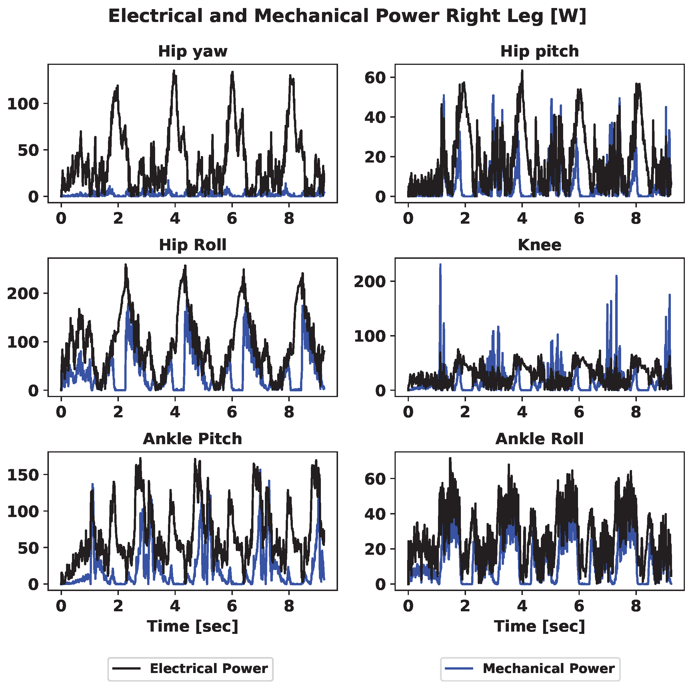
| Joint | Electrical | Mechanical | Efficiency | Electrical | Mechanical | Efficiency |
| Hip—Yaw | 24.59 | 1.21 | 4.91 | 37.22 | 1.72 | 4.61 |
| Hip—Pitch | 18.32 | 7.94 | 43.34 | 17.79 | 5.76 | 32.36 |
| Hip—Roll | 83.99 | 26.52 | 31.58 | 95.45 | 37.79 | 39.59 |
| Knee | 24.95 | 17.42 | 69.82 | 27.92 | 16.65 | 59.65 |
| Ankle—Pitch | 54.57 | 14.34 | 26.27 | 68.12 | 19.26 | 28.27 |
| Ankle—Roll | 16.01 | 8.56 | 54.13 | 26.88 | 14.12 | 52.52 |
| Total | 222.43 | 77 | 37.48 | 273.38 | 95.30 | 38.08 |
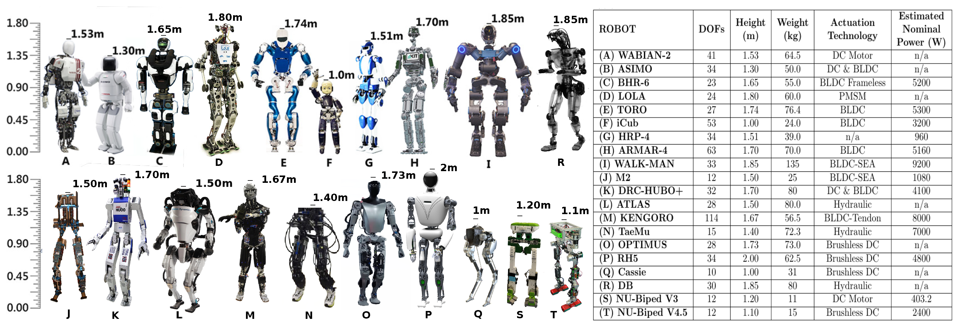
| Robot | DOFs | Height (m) | Weight (kg) | Actuation Technology | Estimated Nominal Power (W) | Power-to-Weight Ratio (W/kg) | Weight-to-Height Ratio (kg/m) |
|---|---|---|---|---|---|---|---|
| (A) WABIAN-2 | 41 | 1.53 | 64.5 | DC Motor | N/A | N/A | 42.16 |
| (B) ASIMO | 34 | 1.30 | 50.0 | DC and BLDC | N/A | N/A | 38.46 |
| (C) BHR-6 | 23 | 1.65 | 55.0 | BLDC Frameless | 5200 | 94.5 | 33.33 |
| (D) LOLA | 24 | 1.80 | 60.0 | PMSM | N/A | N/A | 33.33 |
| (E) TORO | 27 | 1.74 | 76.4 | BLDC | 5300 | 106.4 | 43.90 |
| (F) iCub | 53 | 1.00 | 24.0 | BLDC | 3200 | 133.3 | 24.00 |
| (G) HRP-4 | 34 | 1.51 | 39.0 | N/A | 960 | 24.6 | 25.83 |
| (H) ARMAR-4 | 63 | 1.70 | 70.0 | BLDC | 5160 | 73.7 | 41.18 |
| (I) WALK-MAN | 33 | 1.85 | 135 | BLDC-SEA | 9200 | 68.1 | 72.97 |
| (J) M2 | 12 | 1.50 | 25 | BLDC-SEA | 1080 | 43.2 | 16.67 |
| (K) DRC-HUBO+ | 32 | 1.70 | 80 | DC & BLDC | 4100 | 51.2 | 47.06 |
| (L) ATLAS | 28 | 1.50 | 80.0 | Hydraulic | N/A | N/A | 53.33 |
| (M) KENGORO | 114 | 1.67 | 56.5 | BLDC-Tendon | 8000 | 141.6 | 33.83 |
| (N) TaeMu | 15 | 1.40 | 72.3 | Hydraulic | 7000 | 96.8 | 51.64 |
| (O) OPTIMUS | 28 | 1.73 | 73.0 | Brushless DC | N/A | N/A | 42.20 |
| (P) RH5 | 34 | 2.00 | 62.5 | Brushless DC | 4800 | 76.87 | 31.25 |
| (Q) Cassie | 10 | 1.00 | 31 | Brushless DC | N/A | N/A | 31.00 |
| (R) DB | 30 | 1.85 | 80 | Hydraulic | N/A | N/A | 43.24 |
| (S) NU-Biped V3 | 12 | 1.20 | 11 | DC Motor | 403.2 | 36.6 | 9.17 |
| (T) NU-Biped V4.5 (with battery) | 12 | 1.10 | 15 (21) | Brushless DC | 2400 | 160 (114) | 13.64 (19) |
| Item # | Name | Total Quantity (pcs) | Price (USD) | Total Price (USD) |
|---|---|---|---|---|
| 1 | Gear box | 12 | 100 | 1200 |
| 2 | Motor (Mod:Gartt) | 12 | 100 | 1200 |
| 3 | Encoder (Mod: AS5048a) | 12 | 18 | 216 |
| 4 | ODrive 3.5 | 6 | 170 | 1020 |
| 5 | Aluminum extrusion | 5 | 21 | 105 |
| 6 | MCP 2515 CAN bus module | 4 | 16 | 61 |
| 7 | Arduino Nano | 4 | 7.5 | 30 |
| 8 | Bearing | 12 | 6 | 72 |
| 9 | 3D Printing PLA filament | 1 | 32 | 32 |
| 10 | 3D Printing TPU filament | 1 | 34 | 34 |
| 11 | Force sensor amplifier (mod: HX711) | 8 | 2 | 16 |
| 12 | Force sensor | 8 | 75 | 600 |
| 13 | CNC machine service dedicated to the actuator holders | 1 | 350 | 350 |
| 14 | Bolts | 372 | 0.15 | 55.8 |
| 15 | Nuts | 214 | 0.1 | 21.4 |
| 16 | Electrical cable (8 m) | 1 | 21 | 21 |
| Total Cost (USD) | 4989 | |||
| Human Leg Part | Weight (kg) | Percentage | Robot Leg Part | Weight (kg) | Percentage |
|---|---|---|---|---|---|
| Thigh | 4 | 52% | Upper Leg | 2.46 | 48% |
| Shank | 2.9 | 38% | Lower Leg | 1.94 | 38% |
| Foot | 0.8 | 10% | Foot | 0.76 | 15% |
| Tot | 7.7 | Total | 5.16 |
Disclaimer/Publisher’s Note: The statements, opinions and data contained in all publications are solely those of the individual author(s) and contributor(s) and not of MDPI and/or the editor(s). MDPI and/or the editor(s) disclaim responsibility for any injury to people or property resulting from any ideas, methods, instructions or products referred to in the content. |
© 2023 by the authors. Licensee MDPI, Basel, Switzerland. This article is an open access article distributed under the terms and conditions of the Creative Commons Attribution (CC BY) license (https://creativecommons.org/licenses/by/4.0/).
Share and Cite
Folgheraiter, M.; Yessirkepov, S.; Umurzakov, T. NU-Biped-4.5: A Lightweight and Low-Prototyping-Cost Full-Size Bipedal Robot. Robotics 2024, 13, 9. https://doi.org/10.3390/robotics13010009
Folgheraiter M, Yessirkepov S, Umurzakov T. NU-Biped-4.5: A Lightweight and Low-Prototyping-Cost Full-Size Bipedal Robot. Robotics. 2024; 13(1):9. https://doi.org/10.3390/robotics13010009
Chicago/Turabian StyleFolgheraiter, Michele, Sharafatdin Yessirkepov, and Timur Umurzakov. 2024. "NU-Biped-4.5: A Lightweight and Low-Prototyping-Cost Full-Size Bipedal Robot" Robotics 13, no. 1: 9. https://doi.org/10.3390/robotics13010009
APA StyleFolgheraiter, M., Yessirkepov, S., & Umurzakov, T. (2024). NU-Biped-4.5: A Lightweight and Low-Prototyping-Cost Full-Size Bipedal Robot. Robotics, 13(1), 9. https://doi.org/10.3390/robotics13010009