Next Article in Journal
The Astrobiology of Alien Worlds: Known and Unknown Forms of Life
Next Article in Special Issue
Neutrinos: Majorana or Dirac?
Previous Article in Journal
Is the Copenhagen Interpretation Inapplicable to Quantum Cosmology?
 
 
universe-logo
Article Menu

Article Menu

Article

The NUMEN Heavy Ion Multidetector for a Complementary Approach to the Neutrinoless Double Beta Decay

by
Paolo Finocchiaro
1,*,
Luis Acosta
2,
Clementina Agodi
1,
Carmen Altana
1,
Paulina Amador-Valenzuela
3,
Ismail Boztosun
4,
Sandro Brasolin
5,
Giuseppe A. Brischetto
1,6,7,
Oscar Brunasso
5,
Salvatore Calabrese
1,
Luciano Calabretta
1,
Daniela Calvo
5,
Vittoria Capirossi
5,8,
Francesco Cappuzzello
1,6,7,
Diana Carbone
1,
Manuela Cavallaro
1,
Efrain R. Chávez Lomeli
2,
Irene Ciraldo
1,6,
Grazia D’Agostino
1,
Franck Delaunay
5,8,9,
Haris Djapo
10,
Carlo Ferraresi
11,
Maria Fisichella
1,
David C. Flechas Garcia
12,
Felice Iazzi
5,8,
Laura La Fauci
1,6,
Gaetano Lanzalone
1,13,
Francesco La Via
14,
Roberto Linares
15,
Nilberto H. Medina
12,
Paulo Mereu
5,
Mauricio Moralles
16,
Josè R. B. Oliveira
12,
Luciano Pandola
1,
Alfio Pappalardo
1,17,
Horia Petrascu
18,
Federico Pinna
5,8,
Antonio D. Russo
1,
Diego Sartirana
5,
Onoufrios Sgouros
1,
Selcuk Oktay Solakci
4,
Vasilis Soukeras
1,
Alessandro Spatafora
1,6,
Domenico Torresi
1,
Salvatore Tudisco
1,
Aydin Yildirim
4 and
Vinicius A. B. Zagatto
15 for the Numen Collaboration
add Show full author list remove Hide full author list
1
Laboratori Nazionali del Sud, Istituto Nazionale di Fisica Nucleare, 95123 Catania, Italy
2
Instituto de Física, Universidad Nacional Autónoma de México, Mexico City 04510, Mexico
3
Instituto Nacional de Investigaciones Nucleares, Ocoyoacac 52750, Mexico
4
Department of Physics, Akdeniz University, 07058 Antalya, Turkey
5
Istituto Nazionale di Fisica Nucleare, Sezione di Torino, 10125 Torino, Italy
6
Dipartimento di Fisica e Astronomia “Ettore Majorana”, Università di Catania, 95123 Catania, Italy
7
Centro Siciliano di Fisica Nucleare e Struttura della Materia, 95123 Catania, Italy
8
DISAT, Politecnico di Torino, 10129 Torino, Italy
9
LPC Caen, Normandie Universite, ENSICAEN, UNICAEN, CNRS/IN2P3, 14000 Caen, France
10
Institute of Accelerator Technologies, Ankara University, 06830 Ankara, Turkey
11
DIMEAS, Politecnico di Torino, 10129 Torino, Italy
12
Instituto de Fisica, Universidade de Sao Paulo, Sao Paulo 05508-090, Brazil
13
Università degli Studi di Enna “Kore”, 94100 Enna, Italy
14
CNR-IMM, Sezione di Catania, 95100 Catania, Italy
15
Instituto de Fisica, Universidade Federal Fluminense, Niteroi 24220-900, Brazil
16
Instituto de Pesquisas Energeticas e Nucleares IPEN/CNEN, Sao Paulo 05508-000, Brazil
17
ELI-NP, HH National Institute for R & D in Physics and Nuclear Engineering, 077125 Magurele, Romania
18
IFIN-HH, 077125 Magurele, Romania
*
Author to whom correspondence should be addressed.
Universe 2020, 6(9), 129; https://doi.org/10.3390/universe6090129
Submission received: 2 July 2020 / Revised: 13 August 2020 / Accepted: 16 August 2020 / Published: 19 August 2020
(This article belongs to the Special Issue Neutrinoless Double Beta Decay)

Abstract

:
Neutrinos are so far the most elusive known particles, and in the last decades many sophisticated experiments have been set up in order to clarify several questions about their intrinsic nature, in particular their masses, mass hierarchy, intrinsic nature of Majorana or Dirac particles. Evidence of the Neutrinoless Double-Beta Decay (NDBD) would prove that neutrinos are Majorana particles, thus improving the understanding of the universe itself. Besides the search for several large underground experiments for the direct experimental detection of NDBD, the NUMEN experiment proposes the investigation of a nuclear mechanism strongly linked to this decay: the Double Charge Exchange reactions (DCE). As such reactions share with the NDBD the same initial and final nuclear states, they could shed light on the determination of the Nuclear Matrix Elements (NMEs), which play a relevant role in the decay. The physics of DCE is described elsewhere in this issue, while the focus of this paper will be on the challenging experimental apparatus currently under construction in order to fulfil the requirements of the NUMEN experiment. The overall structure of the technological improvement to the cyclotron, along with the newly developed detection systems required for tracking and identifying the reaction products and their final excitation level are described.

1. Introduction

Neutrinos are currently the most elusive known particles, even though during the last decades we have painfully started to know them better by means of bigger and bigger experiments with increased sensitivity [1,2,3,4]. However, several paramount questions about their intrinsic nature are still open and in need of clear answers in order to shed some light on their peculiarities like the absolute masses, the mass hierarchy, their intrinsic nature of Majorana or Dirac particles [5,6,7,8,9,10,11,12,13]. The discovery of the Neutrinoless Double-Beta Decay (NDBD) would demonstrate that neutrinos are Majorana particles, i.e., each neutrino being its own antiparticle, with relevant consequences on the understanding of the universe [13,14,15]. An important ingredient of the NDBD is the so-called Nuclear Matrix Element (NME), which links the states of the decaying nucleus before and after the decay and enters the expression of the half-life T1/2 of the NDBD, thus possibly providing a handle on the Majorana effective neutrino mass determination. Indeed, the NDBD decay rate can be expressed as a factorization of three terms: the phase-space factor G0ν, the NME M0ν, and the term f (mi, Uei, ξi) containing a combination of the masses mi, the mixing coefficients Uei, and the Majorana phases ξi of the neutrino species
[ T 1 / 2 ] 1 = G 0 ν · | M 0 ν | 2 · | f ( m i , U e i , ξ i ) | 2
M0ν represents the transition amplitude from the initial state | φ i to the final state | φ f by means of the NDBD operator ONDBD
M 0 ν = φ f | O N D B D | φ i
From Equation (1), one can deduce that if the NMEs are established with sufficient precision, the neutrino masses and the mixing coefficients can be extracted from NDBD decay rate measurements. Thus, the determination of the NDBD NMEs is of crucial importance for physics beyond the standard model. The evaluation of the NMEs is presently limited to state-of-the-art model calculations based on different methods (QRPA, shell model, IBM, EDF, etc.). However, the ambiguities in the models are still too large and the constraints too loose to reach accurate values of the NMEs. This is basically because the determination of the NMEs requires the knowledge of the many-body nuclear wave functions. Discrepancy larger than a factor of two between the different models are presently reported in literature.
In this framework, the experimental study of different nuclear transitions where the nuclear charge is changed by two units leaving the mass number unvaried, i.e., where the nuclear wave functions involved are the same as in NDBD, could provide relevant information. NUMEN proposes an innovative technique to access information about the NME, by measuring the differential cross section of heavy-ion induced Double Charge Exchange (DCE) reactions, which is basically proportional to the square of the NME. The two processes are characterized by a number of similarities (same initial and final nuclear wave functions, similar mathematical structure of the involved transition operators and other similarities), provided that the transition occurs from ground state to ground state, as reported in detail in [16].
The main goal of NUMEN is to establish an alternative experimental path to the determination of NDBD NMEs. A campaign of measurements to assess the behavior of the NMEs will be done on different nuclear systems with variable kinetic energy of the projectile.
From the theoretical standpoint, the reaction mechanism can be expressed as the product of three factors, respectively related to the reaction and to the nuclear structure, this last term being the product of projectile and target matrix elements. A microscopic description of the DCE reaction is currently being developed: the nuclear structure part makes use of the Distorted Wave Born Approximation (DWBA), or of Coupled Reaction Channel (CRC) cross sections, in which the reaction part is described in a full quantum scattering picture.
From the experimental standpoint, a systematic set of data will have to face the challenges of the low cross sections and the subsequent requirements of high sensitivity and resolution, in order to pick out the DCE signal in the huge background. The measurement of DCE cross sections foreseen in NUMEN could provide a significant input to the nuclear structure theories of NDBD.
Moreover, NUMEN can provide useful information on the relative weight of the NMEs between different candidate isotopes of interest for the NDBD; indeed, the ratio between the measured cross sections is probably a model-independent way to compare the sensitivity of half-life experiments to different candidate nuclei. This is likely true also in the presence of large systematic uncertainties in the measured cross sections and, consequently, in the DCE matrix elements, as such uncertainties would be mostly cancelled in the ratio. Such a comparative analysis may affect the future experimental developments in the field, possibly driving the choice of the best isotope candidates for NDBD.
Preliminary experimental results obtained at INFN-LNS for the 40Ca(18O,18Ne)40Ar reaction, where 18O projectiles at 270 MeV kinetic energy impinge on a 40Ca target, the 18Ne ejectiles are detected and the 40Ar residuals go undetected, provided an encouraging indication on the capability of the proposed technique to access relevant quantitative information by selecting a zero missing mass in the output channel [16]. Indeed, if the ejectile is identified and its emission angle and energy are measured, the kinematics are completely determined. A detailed description of the NUMEN physics can be found in [17,18,19] and in a dedicated article in this same issue.
The basic tools needed for the NUMEN experiments are the K800 Superconducting Cyclotron and the MAGNEX spectrometer [20,21]. The accelerator has to provide the required heavy-ion beams with excellent energy resolution and low emittance, whereas the large acceptance magnetic spectrometer is essential for the detection, identification, selection, and measurement of the ejectiles. MAGNEX relies on a high-order trajectory reconstruction technique, which makes it possible to reach the experimental resolution and sensitivity necessary for the challenging measurement at forward angles of the DCE cross sections. Unfortunately, the tiny values of such cross sections demand beam intensities much higher than those manageable with the present facility.
The ambitious goal of providing accurate values of the Nuclear Matrix Elements to the neutrino community requires the overcoming of two main limits, i.e., the maximum beam intensity deliverable by the accelerator and the maximum counting rate of the detectors associated with the MAGNEX spectrometer. This gave rise to the POTLNS project, aimed at a challenging upgrade of the LNS cyclotron and at the design and construction of new high-performance detection system for MAGNEX. The project, starting in the second half of 2020, was approved and funded in the frame of a national program aimed at strengthening the research infrastructures identified as priorities, according to the European Strategy Forum on Research Infrastructures (ESFRI).
The tiny cross sections to be measured, even down to few nb, and the consequently needed high beam intensity require very high performance for the whole experimental apparatus. On the one hand, it has to be capable of catching high-resolution data in a stifling rate of nuclear reaction products; on the other hand, it has to respect severe physical and mechanical constraints still withstanding the very high neutron and gamma radiation fields. Moreover, for some of the nuclear systems to be explored by the NUMEN project, the typical energy resolution of MAGNEX with beams provided by the cyclotron is not sufficient to discriminate between the ground state and the first excited states [16]. In such cases, a gamma detector array will be coupled to the magnetic spectrometer to provide the required discrimination between nearby energy states. Designing and building the experimental setup required by NUMEN represents a technological challenge, from the target to the scattering chamber, from the detection systems to the electronics and the radiation shielding.

2. Materials and Methods

Ideally, the DCE reactions to be studied are quite simple: one sends a beam of a suitable nuclear species, typically 18O or 20Ne, on a target made of a NDBD candidate nuclear species, namely one among 48Ca, 76Ge, 76Se, 82Se, 96Zr, 100Mo, 106Cd, 110Pd, 116Cd, 110Sn, 124Sn, 128Te, 130Te, 136Xe, 130Xe, 148Nd, 150Nd, 154Sm, 160Gd, 198Pt. Oxygen and neon were chosen as the most suitable projectiles because they are the lightest even-even stable nuclei with a reasonably high DCE cross section due to super-allowed transitions. Moreover, the requirement of employing very thin targets to preserve the needed energy resolution, as will be discussed later, imposes to employ as light as possible projectiles. The reaction of interest changes two neutrons into two protons in the projectile, and consequently, two protons into two neutrons in the target, or vice versa. Moreover, the reaction must proceed by leaving both projectile and target in their ground or excited states. Such a small energy exchange implies that the reaction must be very peripheral; thus, the scattered projectile comes out at very forward angles with a quite small cross section down to a few nb. In order to disentangle the reactions of interest from the overwhelming amount of forward-going ions produced by all the other nuclear reactions, the solution is to use a high resolution and large acceptance magnetic spectrometer, capable of selecting outcoming particles in a very small range of kinetic energy, mass, and charge, while deflecting away all the rest, i.e., MAGNEX. However, this is not enough due to the tiny cross sections involved, in most cases one needs to increase the reaction rate. This cannot be done by increasing the target thickness, as it would produce an energy degradation of the projectile and of the outcoming product. A thick target would prevent the correct measurement of the energy balance of the reaction and the identification in mass and charge of the detected product due to the mix-up of the expected trajectories inside the magnet. Therefore, the only solution is to increase the beam intensity. An additional complication is due to the need of rotating the whole spectrometer in order to choose its most convenient angular arrangement around zero degrees with respect to the beam direction, in order to cover for each particular reaction most of the useful solid angle.
Notwithstanding the strong magnetic selection, the expected output particle rate from the spectrometer is of the order of 5 × 10⁶ particles per second (pps), distributed over an area of 100 × 15 cm, which requires the setting up of a challenging detection system capable of measuring for each detected particle its position, impinging direction, energy, mass, charge. In addition, in many cases one would also need to measure a gamma ray in coincidence, as a signature of a DCE reaction proceeding through the first or second excited level of the projectile or the target, which is yet a more challenging issue.
In the following the overall framework will be shortly described, consisting of the cyclotron upgrade and the MAGNEX spectrometer, followed by a more detailed description of the setup and of the heavy ion multidetector, currently being developed, consisting of a gas tracker and a Particle Identification Detector (PID) in the focal plane, which together constitute the Focal Plane Detector (FPD) and a Gamma Detector Array (GDA) around the target. For better clarity, the description has been divided into several sections, each one dedicated to a subsystem.

2.1. The Cyclotron Upgrade

The LNS Superconducting Cyclotron is a three-sector compact accelerator. Two pairs of superconducting coils allow to produce a magnetic field tunable between 2.2 and 4.8 T on the mid-plane. Twenty trim coils, wound on each of the six sectors (120 in total), allow to achieve the isochronous magnetic field requested for the acceleration of all the ions, from the singly ionized molecular hydrogen up to uranium, in a wide range of energies, between 10 and 80 MeV/amu [22]. As a consequence of the cyclotron compactness, the orbit separation at the outer turns is small. This limits the extraction efficiency, which is of 50–60%. Most of the accelerated beam is stopped by the septum of the first electrostatic deflector, and despite being water-cooled, serious thermal issues occur when the extracted power exceeds 100 W. The NUMEN experiment plans to use mainly beams of oxygen and neon with intensity up to 1013 pps. The required energies are in the range 15–60 MeV/amu, and the beam power in the range 1–10 kW. Therefore, the extraction of 1–10 kW beams is not feasible using electrostatic deflection. Moreover, the existing extraction channel has small transversal size and no thermal shields to dissipate the beam power coming from beam halos. This is why the cyclotron is going to be upgraded, modifying its magnetic configuration and designing a new channel for the extraction by stripping [23,24,25,26].
In such a scheme the ions are initially accelerated with a charge state q between (Z-2) and (Z-5). Then, after crossing a stripper foil suitably placed near the maximum radius of the machine, they become fully stripped. The curvature radius of their trajectory becomes abruptly smaller and it runs through the cyclotron pole toward a suitable extraction channel (Figure 1). Using this technique, all the ions of interest, with mass number A ≤ 40 and energy E ≥ 15 MeV/amu, can be fully stripped with efficiency higher than 99% [27] and beams can be efficiently accelerated at the desired intensity. In Figure 1 a pictorial sketch is shown of the inner part of the upgraded cyclotron, with an example of trajectory for an accelerated ion before and after being stripped and extracted.

2.2. The MAGNEX Spectrometer

MAGNEX is a large acceptance magnetic device consisting of a large aperture vertically focusing quadrupole and a horizontally bending dipole magnet. It allows the identification of heavy ions with quite high mass (ΔA/A ≈ 1/160), angular (Δθ ≈ 0.2°) and energy resolution (ΔE/E ≈ 1/1000), within a large solid angle (Ω ≈ 50 msr) and momentum range (−14% < Δp/p < +10%) [28,29]. High-resolution measurements for quasi-elastic processes, characterized by differential cross sections falling down to tens of nb/sr, were already performed by this setup [30,31,32,33,34,35,36,37,38,39,40,41,42]. A crucial feature is the implementation of a technique of trajectory reconstruction, based on differential algebraic methods, which make possible the solving of the equation of motion of each detected particle to the 10th order [28,29]. Figure 2 shows a global view of the MAGNEX spectrometer in the current configuration, whereas Figure 3 is a 3D representation of the NUMEN multidetector to be installed on the MAGNEX spectrometer, with the new scattering chamber, the gamma detector array, the input quadrupole, the dipole magnet, the focal plane gas tracker detector, and the particle identification detector.

2.3. Target, Cooling System, and Robotic Handling

The main constraints in the design of the NUMEN targets come from:
  • The heat deposited by the beam in the target;
  • The energy resolution of the DCE reaction products;
  • The required compactness of the whole target/cooling system.
The first issue is related to the very intense heavy-ion beams to be employed. It is planned to use 18O and 20Ne beams with an intensity up to 60 μA, with energies ranging from 15 to 60 MeV/amu. Assuming a gaussian beam spot with a standard deviation of 1 mm, the highest deposited power density in the target will be of the order of 105 W/cm3 for the lowest beam energy (2 to 3 W deposited in a 400-nm thick target). This amount of power would inevitably melt the target material. To prevent such a damage, a dedicated cooling system has been designed.
As for the energy resolution, the kinematics of the DCE reactions will be reconstructed from the energy and scattering angle of the reaction products measured with the MAGNEX spectrometer. In order to disentangle the transitions to the ground state from those to the first excited state of one or both the participant nuclei, the energy resolution should be lower than the energy difference between the two states, usually in the order of 500 keV. In order to attain such a resolution, the targets must be thin (a fraction of a µm) and uniform. Finally, the target system must be as compact as possible, as well as the scattering chamber, thus minimizing the distance between the target itself and the gamma ray calorimeter installed outside on top of the chamber (described in a following section). The first isotopes that have been considered for the target production process are 116Sn, 76Ge, 130Te, chosen as result of a trade-off between scientific priority and technical feasibility, i.e., between the energy resolution and the availability of isotopically enriched material.
Thermal radiation alone is not sufficient to cool down the target, and analytical calculations showed that simply clamping the target with a cold frame does not guarantee its integrity [43,44,45]. The heat dissipation can be enhanced by depositing the target material onto a highly thermally conductive thin substrate. The choice fell on Highly Oriented Pyrolytic Graphite (HOPG), an artificial graphite made by a stack of graphene layers with parallel orientation, which can be produced in thin foils at room temperature. It has an in-plane thermal conductivity of 1950 Wm−1K−1, while the transverse conductivity is about 6 Wm−1K−1. Thanks to the very high in-plane conductivity, heat can quickly flow from the hot beam spot to a cold frame clamping the HOPG substrate and cooled by a dedicated cryorefrigerator (Figure 4). The thin target isotope, typically 400 to 800 nm thickness and 1 cm diameter, will be deposited on a 5-cm diameter and <5-µm thick substrate.
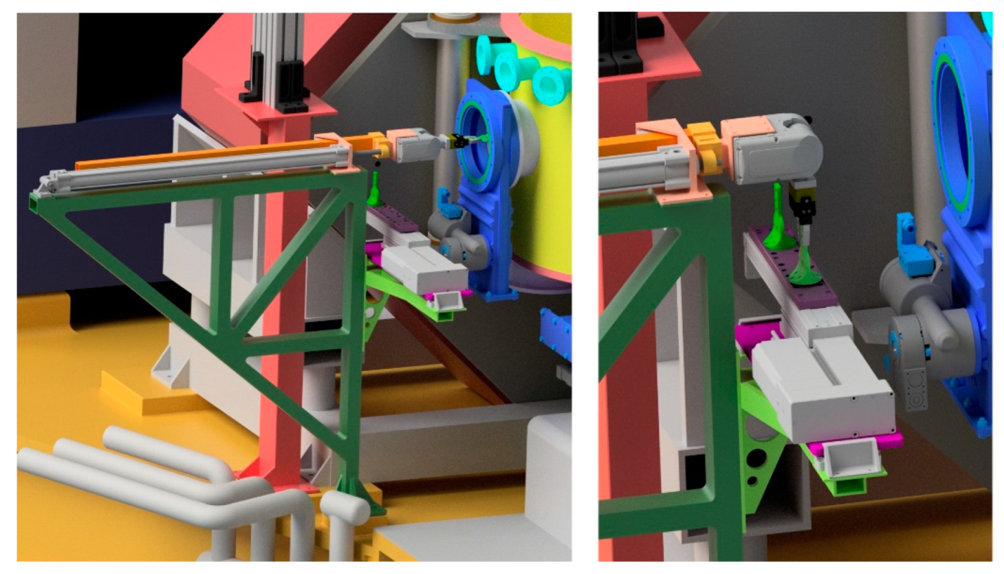
Due to the huge activation following a beam session, the target cannot be handled for quite some time, nor can an operator get close to the scattering chamber. This is why a robotic system was designed for insertion, removal, and replacement of the target [46]. Figure 5 shows the 3D drawing of the robotic arm clamping a target, along with the details of the target hosted on the cold finger of the cryocooler. Figure 6 shows the 3D drawing of the robotic arm while extracting a target through the suitable vacuum valve, and then placing it on the target parking rack outside the chamber.

2.4. Focal Plane: The Gas Tracker

The FPD tracker requires a good resolution of the phase space parameters at the focal plane (Xfoc, Yfoc, θfoc, φfoc), respectively the XY transverse coordinates and the horizontal and vertical angles of the trajectory. Indeed the precise and accurate particle trajectory reconstruction is fundamental for the determination of the momentum vector at the target position [28,29,47], which in turn is needed for the particle identification with MAGNEX. Therefore, the particle identification and discrimination are strongly affected by the resolution of the mentioned parameters. Moreover, the FPD must be capable of operating at high speed due to the expected rate of ≈50 kHz/cm following the accelerator upgrade. The structure of the tracker consists of:
  • a thin entrance window made of mylar;
  • a vertical drift region, polarized with a bottom-up direction uniform electric field, that is the active volume of the detector, which is crossed by the ejectiles of interest;

  • an electron multiplication stage, consisting of three layers of Micro-Pattern Gas Detectors (MPGD) in the multiple thick-GEM (M-THGEM) configuration [48], each one being an insulator plane between two conductor layers with a large number of microscopic holes; close to the holes, the electric field can be very high, thus funneling the arriving electrons and triggering their avalanche multiplication;
  • a segmented multistrip read-out electrode.
The incident charged particles exiting the MAGNEX dipole cross the thin mylar window, whose thickness is typically chosen between 1.5 and 6 μm according to the beam type and energy. They leave a track of ionized atoms and electrons in the low-pressure gas between the cathode and the electron multiplication stage. Under the uniform electric field, the electrons drift with constant velocity toward the MPGD. As soon as reaching the multiplication element, electrons are conveyed into the holes by the strong electric field. The produced electron avalanches reach the segmented read-out electrode, where the projection of the particle trajectory on the horizontal plane is reconstructed.
By also measuring the drift time of the electrons in the gas, one can reconstruct the projection of the trajectory on the vertical plane. From the two projections, the full track of the ion can be reconstructed (i.e., XY impact point coordinates and incidence angle at the focal plane). However, in order to minimize the number of parameters to be acquired, as well as the corresponding electronic channels, the three MPGD planes only contain five spaced rows of holes (Figure 7), and the segmented read-out electrode consists of a set of finely spaced strips orthogonal to these rows. This way, each particle track produces five points on the XZ plane and five on the YZ plane, whose linear fits give rise to the desired quantities. The operating principle is illustrated in Figure 8.
The tracker has an active volume of 1122 × 185 × 108 mm3 and is made of eight modules joined together. One of these modules has been used as prototype for testing purposes, and the test results will be described in detail in the Results section (Figure 9). This prototype, with mechanical and electrical features very similar to the final FPD but only being smaller in the horizontal direction, allowed easier tests in a smaller chamber. The applied voltages, the gas pressure and flowing system, the multiplication technology, and the front-end and read-out electronics are among the main features tested with the smaller size prototype.
The drift region, which extends vertically for 18 cm, is delimited by the cathode on the bottom and the MPGD multiplication stage on top, and was designed to produce a uniform electric field of about 50 V/cm. The left and right sides of the field cage are made of printed circuit boards, whereas the front and back are double rows of gold-plated tungsten wires, 50-μm thick, connecting the two lateral walls and arranged in steps of 5 mm. Electrostatic simulations based on the Poisson Superfish code [49] have been performed in order to model and design the field cage in the drift region, taking into account the presence of a much stronger electric field in the electron multiplication region (MPGD + anode strips) of the mylar entrance window at ground potential and of high voltage PID-wall elements (see later) very close to the drift region on its exit side. With such a simulation, the static electric field in the detector geometry was calculated by iteratively solving the field equations, minimizing the possible perturbations of the uniform drift field.
The chosen gas is pure isobutane (C4H10), which is also a quencher and is excellent for operations with heavy ions at low pressure, even though the use of different gas mixtures is not excluded in the future. The operational pressure is in the range 10–100 mbar, to be set depending on the different experimental conditions (ions of interest and their kinetic energy). Isobutane features a high drift velocity, which is in the saturated regime with the chosen electrical field and pressure values.
The intrinsic rate capability of the M-THGEM is higher than 106 Hz/mm2, much higher than needed for NUMEN, with a sub-millimeter spatial resolution and few ns time resolution (see [50] and references therein). The electron multiplication process occurs by means of an avalanche within the holes along the successive multiplication stages, under the action of the strong electric fields resulting from the application of suitable voltages between the electrodes. The intrinsically robust confinement of the avalanche volume within the M-THGEM holes provides an efficient reduction of the photon-induced secondary effects, resulting in a high-gain capability over a broad pressure range, including low pressure operation. An ad hoc M-THGEM was developed for the NUMEN tracker, with the holes arranged in five equidistant rows orthogonal to the strips on the readout board.

2.5. Focal Plane: The Particle Identification Detector

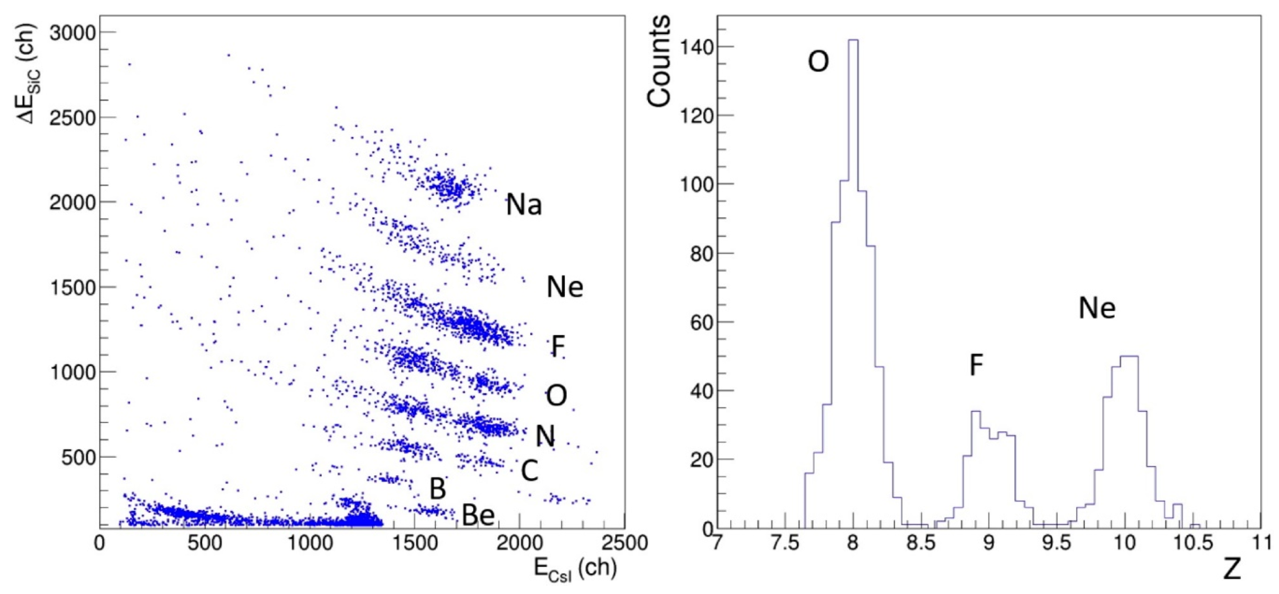
The gas tracker does not provide accurate information on the ion energy loss, thus the particle identification for NUMEN is demanded to a dedicated wall of telescope detectors downstream from the tracker. It must allow the unambiguous identification of atomic species and their isotopes in the region of O, F, and Ne. The most relevant aspects considered in the design of such detection system are related to:
  • The radiation hardness, since the expected overall heavy-ion fluency will be of the order of 1011 ions/(cm2·yr).
  • The energy resolution ΔE/E, which must be better than ≈2%, in order to provide identification of atomic number and mass of the same quality as in the present configuration (ΔZ/Z ≈ 1/48 and ΔA/A ≈ 1/160 [28,29]) or at least to allow an unambiguous identification of the ejectiles of interest, characterized by an atomic number Z ≈ 10 and mass number A ≈ 20. The energy resolution has to be good enough to attain sufficient sensitivity in the cross-section measurements, which is limited by the spurious events falling inside the identification graphical cuts.
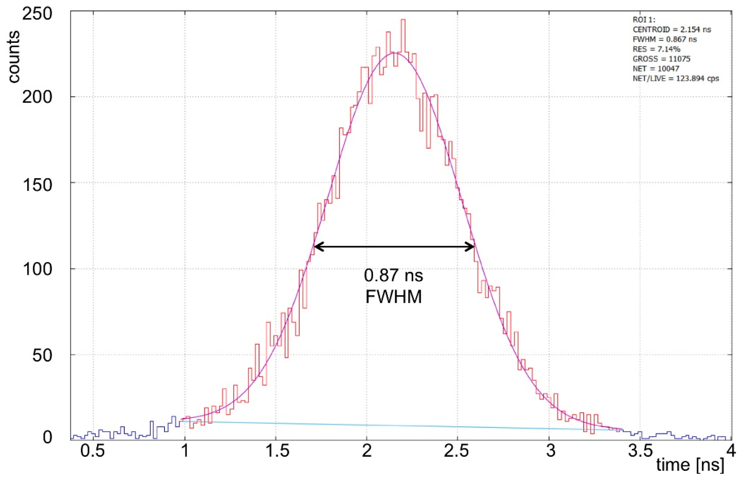
  • The time resolution in the measurement of Time Of Flight (TOF) of the ejectiles from the target to the focal plane and of the drift time of primary electrons in the gas tracker. A TOF measurement with resolution better than 2–3 ns [32] is necessary to effectively suppress the background in the coincidence events with the Gamma Detector Array (see later). As seen before, the drift time is required to reconstruct the YZ projection of the tracks, and a time resolution of the order of 5 ns is needed [51].
  • The degree of segmentation needed in order to keep the double-hit probability below 3% requires elementary detection cells not larger than 1.5 × 1.5 cm2.
  • The scalability, so that a large number of detectors can be built, assembled and managed at a reasonable cost also in terms of time required for the calibration procedures and data analysis.
  • The physical coupling with the tracker, which requires that the PID wall work in a low-pressure gas environment, where the presence of high voltages is also to be considered.
Several nuclear physics experiments [52,53,54] have adopted the telescope solution to identify and study reaction products. It consists of two detectors chosen and assembled in order for the particles of interest to cross the first one and stop into the second one. The correlation between the energy ΔE lost in the thin detector and the residual energy Er deposited in the stopping one is a function of the atomic number Z of the detected ion through the Bethe-Bloch formula [
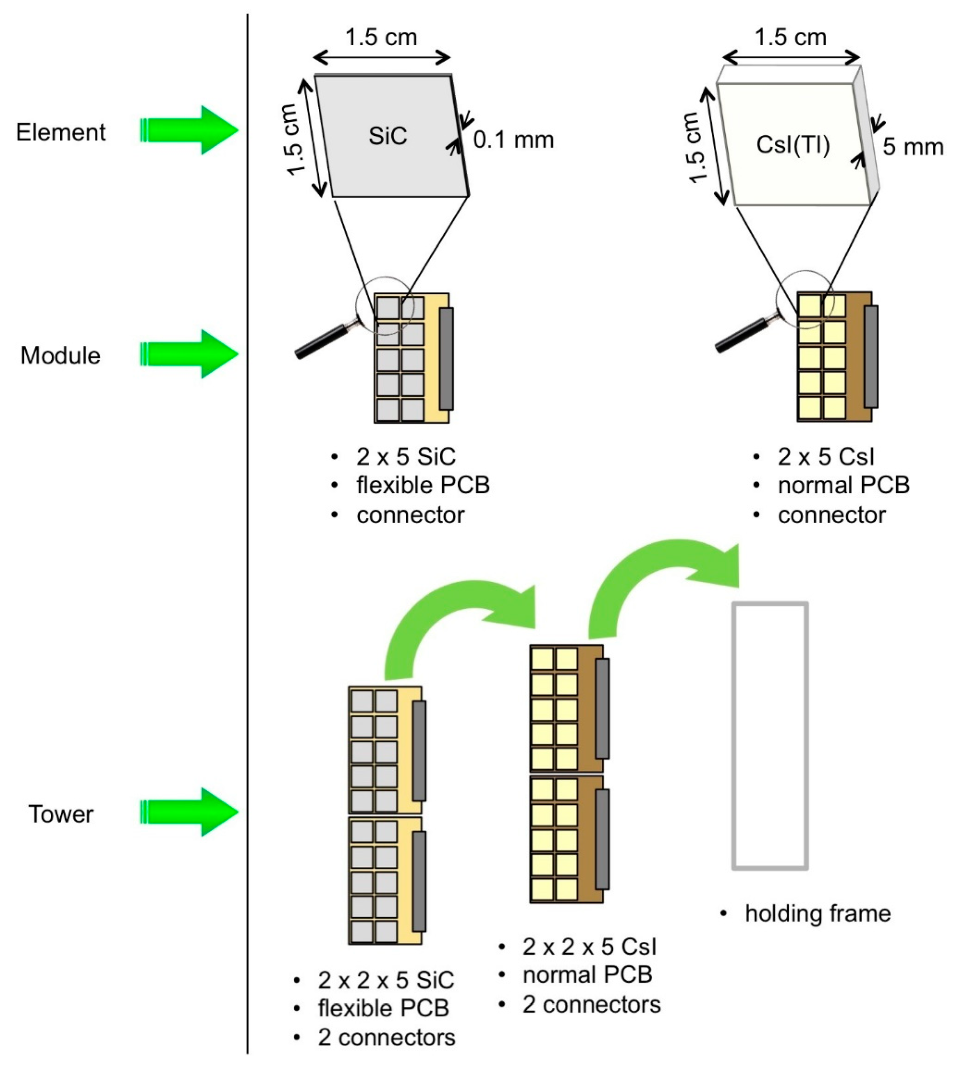
55]. Due to their good energy resolution and linearity, a thin silicon detector or even a gas detector is typically used as ΔE stage, followed by a thicker silicon. This configuration easily provides a good Z identification and energy resolution with an acceptable stopping efficiency, but is limited by the radiation hardness of silicon. Telescopes based on thin silicon carbide (SiC) detectors and thicker inorganic scintillators made of thallium-doped caesium iodide (CsI(Tl)) were chosen and tested as the NUMEN solution for particle identification. Figure 10 shows the scheme of such an elementary telescope cell, which is the basis of the PID system.
The PID, expected to withstand a counting rate of ≈5 kHz/cm2, is an array of 820 tiny identical ΔE-Er telescopes covering the focal plane of the spectrometer. Each detector cell covers an active area of 1.5 × 1.5 cm, with a 0.2-mm dead space between cells. The thickness of the SiC ΔE layer is 100 µm, whereas with the CsI(Tl) Er layer, all the particles are stopped, is 5-mm thick, and is coupled to a Hamamatsu S3590 photodiode of 1 × 1 cm active area [56]. The single detector cell must be capable to handle such a rate and to withstand the corresponding radiation damage, also considering that the impinging particles will be heavy ions. As a reference, the useful energy range for a 16O ion is minimum 10 MeV/amu to reach the Er stage and maximum 75 MeV/amu to be stopped in there. Figure 11 shows a calculation of the energy loss profile in the telescope for an impinging 16O ion with 20 MeV/amu kinetic energy, taking into account also the dead layers, i.e., the SiC backing and the front reflector of the scintillator. Figure 12 shows the same calculation for an 16O ion with 70 MeV/amu.
SiC was chosen among the “robust” radiation-hard materials also thanks to the technological improvements achieved within the SiCILIA project [57]. SiC is a compound semiconductor characterized by an energy bandgap of 3.23 eV. It is thermally stable up to about 2000 °C, even in oxidizing and aggressive environments [58]. Some of its main physical properties as compared to those of Silicon at room temperature are listed in Table 1.
The first requirement for the PID wall is the radiation hardness, i.e., the tolerance of its detectors to high doses of heavy ions. This is strictly related to the damage created in the lattice by the impinging particles [59]. Due to the strength of its chemical bonds (higher average energy required to displace an atom), SiC is a very valid alternative to Si for the production of radiation hard detectors. Its wider band gap reduces significantly the rate of thermal noise whereas, on the other hand, it also represents a disadvantage: the consequently higher average energy required for the generation of an electron-hole pair produces less than half the charge signal than silicon. As for the time resolution, due to the high bias voltage, the charge collection time is much faster than on silicon, thus easily allowing a sub-nanosecond timing.
Nonetheless, the heavy ions to be detected in NUMEN give rise to a large number of primary e-h pairs so that the statistical fluctuations are not an issue. Moreover, SiC detectors can withstand much higher temperatures than silicon detectors, still keeping a high signal to noise ratio. The chosen thickness of 100 µm is such that the expected range of energy loss under typical experimental conditions is ΔE ≈ 15–50 MeV.
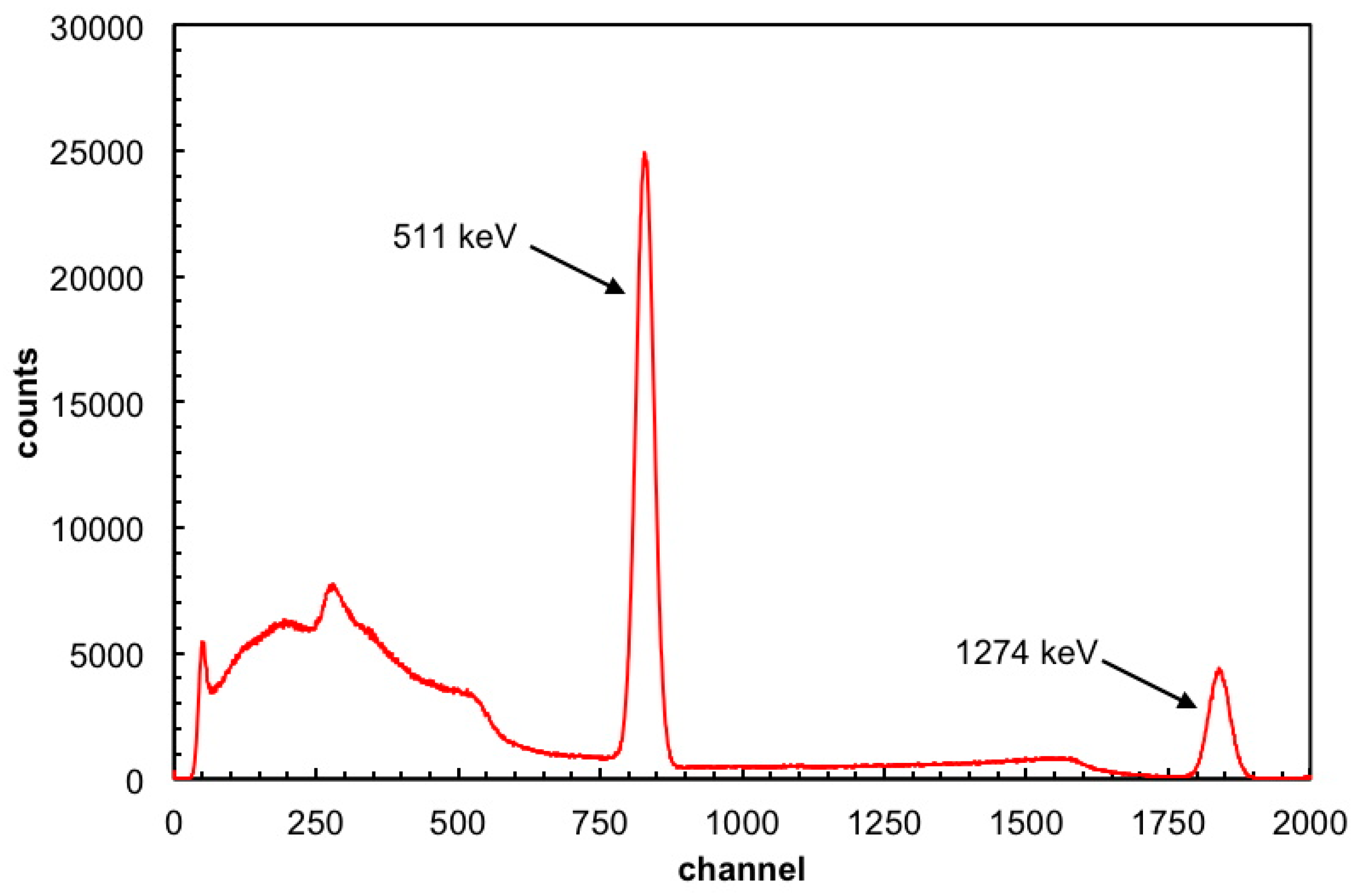
As for the Er detector, when hit by radiation it produces scintillation light with a spectrum centered around 540 nm and a decay time constant τ ≈ 3 µs, whose readout is performed by means of a PIN photodiode. The suitability of such a scintillator for the particle identification task in NUMEN requires an energy resolution around 2% for the ion species at the energies of interest. As will be shown in the Results section, such a resolution (or even better) is feasible, as well as a satisfactory radiation hardness.
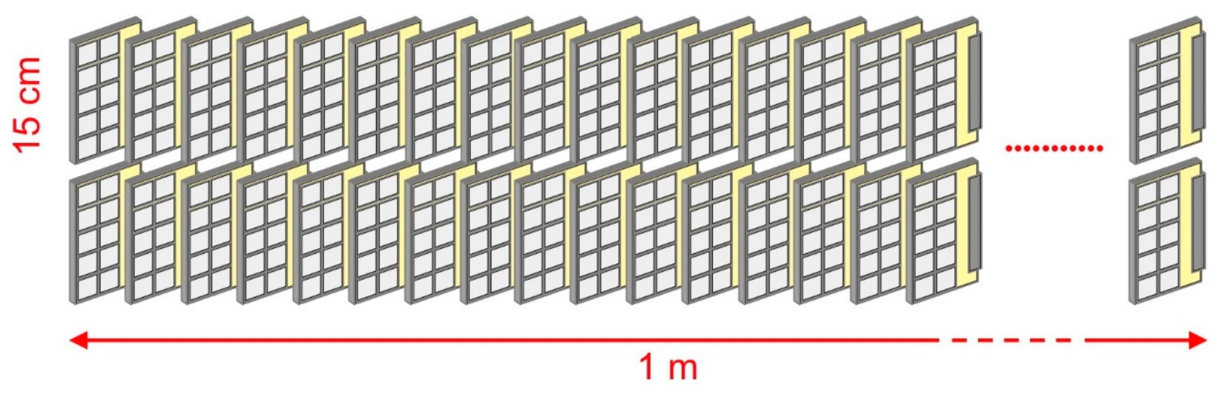
In order to keep a reasonable modularity, it was decided to arrange the elementary cells into independent modules, each one consisting of 10 telescopes (elements). The modules are arranged in groups of two into towers (Figure 13). The full width of the MAGNEX focal plane (1 m), will be covered by 41 towers rotated by about 35° with respect to the vertical axis to make up for the tilting angle of the focal plane with respect to the dipole magnet output (Figure 14).

2.6. The Gamma Detector Array

The nuclear transitions to be studied in the NUMEN project entail the production of deformed and non-deformed nuclei by means of the DCE or competing reactions. The energy resolution of MAGNEX with the beams provided by the cyclotron, ΔE/E ≈ 0.2%, is adequate to discriminate between the ground state (Iπ = 0+) and first excited states (Iπ = 2+) of both projectile-like and target-like species only for the cases of non-deformed target nuclei and at low incident energy. For nuclei of interest in moderately and strongly deformed mass regions, such as 110Pd, 150Nd, and 160Gd, and in all the cases of higher incident energy, the spectra at the focal plane alone cannot resolve between states of the reaction products. In such cases, a gamma detector array close to the target region has been considered as an ancillary device to the magnetic spectrometer, to be used in coincidence with projectile-like fragments in the FPD in order to provide the necessary discrimination between nearby energy states.
Due to the high beam intensities to be used in the DCE experiments, the target region will become a very strong source of radiation, mostly gamma rays, fast neutrons, and electrons, but also light and heavy ions. The charged particles as well as the low energy X-rays can be absorbed by a sufficient amount of solid material between the target and the array. The expected rate of gamma rays and neutrons is such that no solid state detector could be reasonably employed, both for reasons of radiation hardness and speed. Indeed, the total gamma emission rate expected for the typical NUMEN experiments can easily reach 108–109 gamma/s. In addition to that, a comparable amount of neutrons can be expected, which could also produce signals in the gamma detectors.
This means that the solid angle covered by each individual detector element has to be kept small in order to minimize the pulse pile-up probability, whereas in contrast to that, the DCE cross sections are extremely small. In light of all this the resulting requirements for the GDA are:
  • large total solid angle;
  • small solid angle of the individual detectors;
  • high granularity;
  • speed, with signal duration ≤100 ns;
  • good energy resolution, <10% FWHM in the hundreds of keV region;
  • high photopeak efficiency;
  • reasonable radiation hardness.
Inorganic scintillators are normally quite tolerant to gamma and neutron radiation, and among them the LaBr3(Ce) (from now on simply abbreviated as LaBr) was chosen to be employed in the gamma array due to its special features, which fulfil all of the mentioned requirements [60,61,
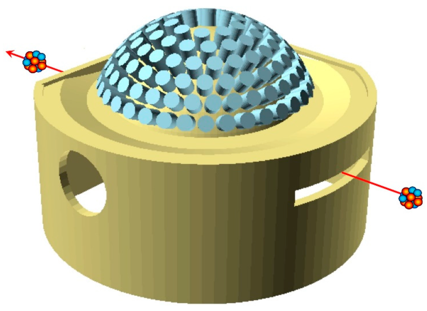
62]. The proposed configuration for the GDA, sketched in Figure 15, consists of 139 LaBr cylindrical scintillators, 38 mm diameter and 50 mm length, readout by means of photomultiplier tubes (PMT). They are arranged in six concentric rings to be positioned upon the scattering chamber, pointing at the target at 25 cm distance and covering ≈20% of the total solid angle.
The typical energy resolution of LaBr is ≈3% with gamma rays of 662 keV (from a reference 137Cs source), the decay constant of the scintillation light is ≈30 ns, which gives access to subnanosecond time resolution, and the expected photopeak efficiency for the GDA crystals of the chosen size is ≈33%. These features make possible to set narrow energy windows on the measured gamma spectra, corresponding to the first or second excited levels of the residual nucleus, along with a suitable narrow time window in coincidence with the ejectile, thus rejecting a huge amount of background events.

2.7. Electronics and Data Acquisition

The primary task of the NUMEN front end and data acquisition system (DAQ) is to cope with the huge analog data rate coming from the detector subsystems. Then, data have to be converted to digital and finally transferred to a storage system via large bandwidth channels. Apparently, this sounds like a standard procedure; however, there are a few constraints that make it difficult, if not challenging.
Due to the intrinsic nature of the MAGNEX magnetic spectrometer, the tracking algorithm is quite complex and consequently slow. Indeed, it requires to sample the signals from many strips in the tracker and to recognize those that belong to a track, performing weighted averages of signals from neighboring wires and matching them to signals from telescopes in the PID detector system. Together with the 90 k events/s/strip maximum expected counting rate, this prevents any real time selection, event building, and processing. Only typical noise suppression by means of thresholds on individual signals can be realistically foreseen.
Concerning the PID, the expected event rate is a few thousand events/s/telescope. In this case, one can think of performing a noise reduction by means of thresholds and elementary ΔEE coincidences. The GDA will face a huge incoming event rate whose handling will presumably be possible only during dedicated runs with a reduced beam current.
The basic DAQ requirements for the three subsystems can be summarized as follows.
  • Tracker: medium energy resolution, ≈1ns time resolution, very high speed.
  • PID: high energy resolution, ≈1 ns time resolution, high speed.
  • GDA: high energy resolution, ≈1 ns time resolution, very high speed.
An originally proposed solution based on an existing ASIC, not well tailored to the NUMEN needs, was discarded in favor of a better suited solution based on commercial products. This sounds quite beneficial from the point of view of the maintenance and repair, hardware/firmware updates, backward compatibility in case of new developments and products. Obviously, the question was whether a feasible commercial solution existed, and it sounded reasonable to try opting for a waveform digitizer approach with underlying FPGA firmware/hardware. Such an approach looks powerful and flexible, as it is open to tuning and rearrangements that in case of more traditional electronics would require hardware replacements. However, within a digitizer framework, the idea of recording the waveforms is not suitable at all, due to the large number of channels and to the continuous mode of operation of the accelerator (in other facilities, with 1–2 s long duty cycles and smaller number of detectors, there is time between beam bursts to store the acquired waveforms).
The solution was found in a new high-performance 64-channel digitizer with 125 MHz sampling rate (VX2740 [63]), which has also been chosen by the Darkside experiment [64]. Such a module will provide several advantages:
  • uniform front end and readout hardware architecture;
  • reduction and simplification of the spares;
  • programmable signal handling algorithm, tailorable to each detector type;
  • very good energy resolution, 16-bit conversion;
  • very good timing capabilities, in 8-ps steps;
  • pile-up detection and tagging; 

  • high data throughput, nominally up to 10 Gbit/s;
  • cost reduction due to purchasing only one model for all the detector subsystems.
The VX2740 digitizer development is still being finalized: the hardware is ready whereas the firmware for the FPGA is still being tuned in order to accommodate also some special requests from the Darkside experiment. The new generation FPGA has quite a higher number of gates with respect to previous digitizers, thus allocating more hardware-emulating algorithms and a quad-core processor hosting a real time Linux operating system.
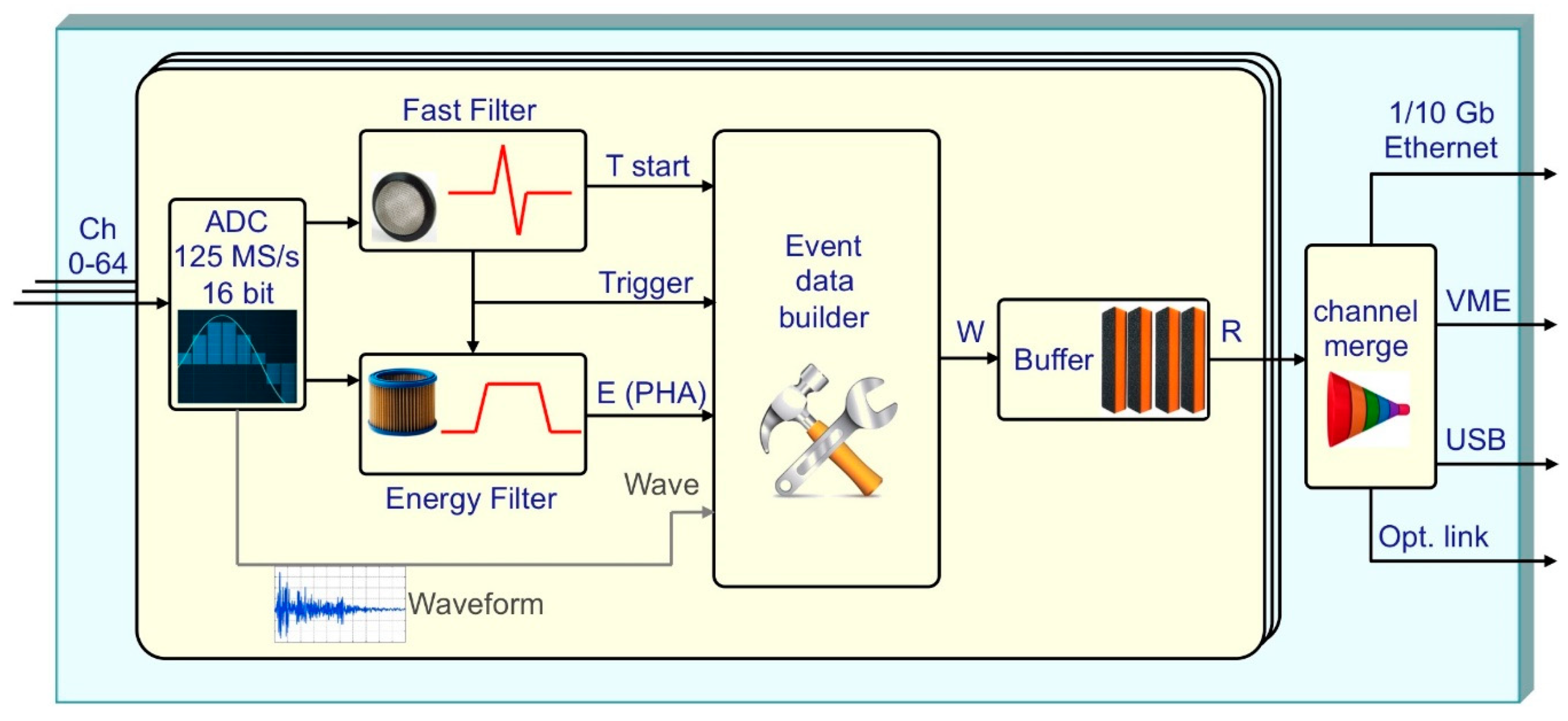
All the signals from the tracker and the PID will be handled by charge-sensitive preamplifiers, and their outputs will go directly to the VX2740 inputs. Here, a fast flash-AD conversion occurs at 125 Msample/s, the FPGA operates a suitable recursive numerical transform implementing a CR-RC2 filter, producing a bipolar signal whose zero crossing time, interpolated at 8-ps steps, is used as detection time. In parallel, a different recursive numerical transform on the digitized input signal produces a trapezoidal shape, whose flat-top height is proportional to the original signal amplitude. These operations are performed on-the-fly in real time and independently for the 64 channels by the on-board FPGA, not introducing additional dead time and therefore resolving or tagging the signal pile-up depending on the relative delay between two consecutive signals. The same numerical analysis is performed for the GDA signals, with the only difference that they do not need to be preamplified because they are produced by PMTs. The block scheme of the operational features of the VX2740 module is depicted in Figure 16.
A simple on-board logic operation will help reducing the noise on the PID telescopes, mainly due to gamma rays triggering the scintillating stage made of CsI(Tl): by coupling ΔE and Er signals on the same module, the FPGA can easily discard the uncorrelated hit and only accept those with valid coincidences.
The DAQ will operate in free-running mode and the event building will be done at a later stage. The data will be produced in form of hits, each one taking nine bytes according to scheme of Figure 17 and freely flowing out of each module via a 10 Gbit/s Ethernet interface through concentrators toward the storage system.
The overall data output rate depends on the NUMEN running mode. Two main modes are foreseen: inclusive and exclusive. The inclusive mode, for shorter periods at high beam current (nominal 1013 pps), does not consider coincident GDA data whose rate would be prohibitive. The exclusive mode, in coincidence with the GDA, is only feasible with lower beam current (nominal ≈1012 pps). In both cases the maximum expected output data rate is of the order of 50–60 MBytes/s.

3. Results

The systems described in the previous section have been extensively tested under realistic conditions to prove that their components can attain the required performance in terms of resolution, rate capability, radiation tolerance. The detectors were tested with radioactive sources and with beams, whereas targets and mechanical components underwent tests in extreme conditions. In the following subsections, several results will be summarized.

3.1. Target Cooling System

In order to study the target cooling system and validate its concept, a smaller scale prototype was built using a preexisting cryo-refrigerator. A target prototype, a HOPG graphite foil 10-μm thick, was screwed to the cold finger of the refrigerator that was installed on the bottom of a spherical vacuum chamber. An infrared laser diode was employed as heating source, and its light was shone onto the target by means of a suitable optical fiber. The target temperature was monitored by a thermocouple and an infrared camera took pictures of the target surface to study the 2D heat distribution. Figure 18 Left shows the spot, in false colors, heated by the optical fiber. The temperature gradient indicates the capability of the graphite to dissipate the heat towards the heat sink, and the symmetrical radial distribution testifies that it was well clamped by the copper supports guaranteeing an optimal thermal contact. Indeed, the plot in Figure 18 Right shows the time behavior of the system and proves that its temperature stabilizes asymptotically. The same setup was then used to test a realistic target made of an 800-nm layer of tellurium evaporated on the HOPG graphite foil. Even in this case, the temperature stabilized at a quite reasonable value well below the melting value. An inspection at the end of the test did not show any damage on the target sample.
It is worth remarking that the deposition of the target material onto the HOPG backing represents in itself a quite challenging task, due to the small thickness and high uniformity required by the overall energy resolution required. A detailed description of the problem and of the related technological procedures can be found in [43,44,45].

3.2. Focal Plane: The Gas Tracker

A dedicated beam line named TeBe (Test Bench) was set up at LNS for the test of materials and prototypes in view of the NUMEN development. It is equipped with a small multiport vacuum chamber where one can easily install small detector prototypes for direct irradiation with beams, in case of radiation tolerance tests, or for scattering from a target to test the detector properties. The smaller scale tracker detector of Figure 9 was extensively tested with beams and alpha sources in the TeBe chamber in order to characterize its behavior as a function of many parameters: field shaping and drift voltages, MPGD bias voltages, currents, gas type, pressure and flow rate, tolerance to discharges, particle rate, etc. Even though additional fine tuning will still be possible for each particular experiment, the overall operating parameters have been studied, understood, and decided.
Every time a particle crosses the detector, the electrons produced by the ionization in the gas drift upwards and are multiplied in the MPGD only in correspondence of the five rows of micro-holes. Behind each of these rows, the electrical induction produces a signal on a few strips, therefore the crossing particle gives rise to five clusters of few solicited strips. A weighted average of the charge signal induced on the strips of each cluster gives the five X coordinates with a submillimeter resolution (Figure 19 Left).
In principle, the X reconstruction could present a left-right ambiguity, but in this case it can be excluded because of the large tilting angle of the tracker, which only allows trajectories with negative impinging angle with respect to Z. The five corresponding drift times, referred to the precise arrival time of the particle on the PID, give access to the Y coordinates by means of the drift velocity, which as said before, is saturated, thus constant at 5 cm/µs. The resolution on Y is submillimeter as well (Figure 19 Right). In Figure 20, a sketch of a 3D track reconstruction is shown, by means of the combined XZ and YZ projections of Figure 19, following the scheme of Figure 8.
An alternative configuration is currently being studied, which is more efficient to resolve ambiguities due to the high occupancy of the detector channels. It features a full M-THGEM and five rows of pads instead of strips on the anodic readout plane. An example of such a configuration, shown in Figure 21, was simulated. On the one hand, the overall number of readout channels is equivalent, as the foreseen pads would be much larger than the strips. On the other hand, the track reconstruction would be done by fitting the centroids of the five charge distributions, each one as a weighted average of several pads on the same row.
Not surprisingly, such a linear fit would provide a submillimeter position resolution on the focal plane, as shown in Figure 22, while at the same time insuring a much lower occupancy of the readout channels and strongly reducing the ion back-flow in the gas. A prototype of such a configuration will be soon constructed and tested to verify the simulation results.

3.3. The Particle Identification Detector

The radiation hardness of the SiC detector to be employed as ΔE stage was tested with an 16O beam at 25 MeV. The response of a SiC detector was compared to a silicon detector in terms of resolution and Charge Collection Efficiency (CCE) at increasing values of ion fluence. While the silicon detector started to be deteriorated at 109 particles/cm2 and was permanently broken after 1010 particles/cm2, the CCE of the SiC detector only went down to 20% after 1013 particles/cm2. Moreover, a one-day annealing at room temperature restored it up to 45%. As for the energy resolution, the initial value of 0.3 MeV FWHM worsened to 0.7 MeV after the irradiation with 1013 particles/cm2, but after the annealing it was almost completely recovered.
A 1-cm2 CsI(Tl) crystal was tested for radiation tolerance under realistic conditions by means of direct irradiation with a 14N beam at 62.5 MeV/amu in the TeBe test chamber. A histogram of the output amplitude spectrum was produced by reducing the beam intensity to 104 particles per second (pps) before the irradiation. Then the crystal was irradiated with 7.5 × 10¹¹ ions, and finally the same histogram was produced after reducing the beam intensity back to 104 pps. Neither amplitude drift nor resolution loss were observed, thus implying that the PID should be perfectly operational at least for 80 beam-days at full intensity, equivalent to several years of experiments.
A simple extrapolation, starting from the known features of the detection elements, says that the 2% energy resolution required to correctly identify and discriminate the detected nuclear species is feasible with the telescope. Nonetheless, a test under realistic conditions was performed with a beam of 18O at 15.5 MeV/amu on a Selenium target, in order to prove that the identification and discrimination could be achieved with the proposed telescope configuration. A single telescope was installed inside the MAGNEX scattering chamber and positioned at 15 degrees with respect to the beam direction and 20 cm distance from the target.
The resulting ΔEEr plot (Figure 23) shows an excellent atomic number resolution ΔZ/Z ≈ 0.16 between the nine adjacent nuclear species detected. It has to be remarked that the light signal from the CsI(Tl) scintillator is proportional to the deposited energy, but the proportionality constant is different for different Z, therefore, this requires a preliminary calibration, which allows the correct energy scaling between the detected species.

3.4. Tracker and PID: Selection of the DCE Reaction Channel

The main goal of the NUMEN multidetector, i.e., the selection of the DCE reaction channel, is a complex task that calls into play the combined action of the PID, the tracker, and MAGNEX. Indeed, in order to successfully perform such a selection, one has to unequivocally identify and select the particles hitting the PID. The identification capability consists in the correct attribution of charge and mass to the detected particles. As the PID telescope only provides information on the nuclear charge Z, one has to use the MAGNEX properties by means of the tracker to select the correct isotope, i.e., the mass number A.
The mass identification technique used in MAGNEX exploits the properties of the Lorentz force. When dealing with such a large acceptance device the best resolution in the identification technique is achieved by performing a precise reconstruction of the kinetic energy of the transported ions [29]. However, when a high precision mass resolution is not necessary, as in the experimental conditions of the NUMEN reactions, which involve oxygen, fluorine, and neon ions, the identification procedure can be successfully performed by correlating the horizontal position on the focal plane (Xfoc) and the residual energy measured by a stop detector (Er). The relationship between these two quantities is approximately quadratic with a coefficient depending on mass and charge
X f o c m q E r
And, therefore, in a Xfoc versus Er plot the events are distributed on different loci according to the ratio m q . We remark that q in Equation (3) is the ion charge and not the nuclear charge Z, so that the telescope identifies Z, whereas the magnet selects particles based on their mass and ion charge: isobars leaving the target in equal charge state will follow similar trajectories, and knowing Z makes it possible to disentangle the different nuclei and charge states. A precise measurement of Xfoc is performed by first matching the rough position given by a hit telescope with the information from the tracker, which allows a very precise determination of the impact position and direction. The knowledge of the incoming direction is quite useful for additional fine corrections on the energy measurement, due to the different effective thickness crossed by the particles incoming with different angles. A feasibility test was done with a 20Ne beam at 20 MeV/amu impinging on a thin 12C target. The MAGNEX spectrometer was configured with its optical axis at 10° with respect to the beam direction. A SiC-CsI(Tl) telescope placed on the focal plane of MAGNEX was employed for the ΔEEr measurement, whereas the tracking information was obtained by means of the currently existing wire chamber of MAGNEX [65]. After selecting the oxygen ions on the ΔEEr plot (Figure 24 Left), a linearization and projection procedure made it possible to build the distribution of ejectiles as a function of their atomic number Z (i.e., nuclear charge, Figure 24 Right). After selecting the events under the oxygen peak, we then built the Xfoc versus Er plot (Figure 25 Left) where the isotopic separation is clearly visible. Another linearization and projection procedure made it possible to build the distribution of oxygen ions as a function of their mass number (Figure 25 Right). The measured resolution in charge and mass is ΔZ/Z ≈ 4.1% and ΔA/A ≈ 2.1%, enough to clearly identify the ejectiles of interest for the NUMEN purposes.
Finally, the knowledge of charge state, atomic number, mass, kinetic energy, impact position, and direction on the focal plane, thanks to the trajectory reconstruction technique implemented in MAGNEX [28], allows to provide a signature on the DCE reaction and to infer the emission angle θlab of the ejectile from the target. This can be connected to the excitation energy of the final nuclear system (Ex), by a missing mass calculation based on relativistic energy and momentum conservation laws, assuming a binary reaction [47]. As an example, in Figure 26, we show the reconstructed scatter plot θlab vs. Ex obtained in the 76Se(18O,18Ne)76Ge reaction at 15.3 MeV/amu incident energy. This is one of the DCE reactions of interest for the NUMEN project, since 76Ge is a candidate for the double beta decay process. This representation is quite useful, since it contains the parameters needed to extract the absolute DCE cross section, which is the experimental goal of the NUMEN project. The transition that we need to select is toward the 76Ge ground state, which is represented by the data points located around a vertical straight line around Ex = 0 with an expected resolution of the order of 300 keV FWHM. We remark that such a resolution is the result of the combined features and resolution of all the detector systems described above. As one can see the number of points is quite small, due to the tiny cross section, and this is why a high beam intensity is required. By projecting these data on the vertical axis θlab it is possible to extract the angular distribution for the ground state to ground state transition.

3.5. Gamma Detectors and Front-End Electronics

The GDA represents a twofold challenge as it has to withstand a very high input rate, while at the same time ensuring a very good energy resolution. It is well known that the LaBr scintillator is so far the best gamma detector after the cooled Germanium semiconductor, which is very easily damaged by fast neutrons. If using Germanium, one has to live with an intrinsic limitation in the sustainable counting rate. Conversely, LaBr is very fast and can be operated at a high counting rate. In the NUMEN environment, with a high beam current up to 1012–1013 pps, the number of gamma rays produced in the target will be huge: simulations based on experimental cross section data foresee counting rates of the order of 105 cps on each detector produced by any kind of nuclear reaction in the target [66]. The challenge is in selecting only those correlated with the ejectile of interest going through MAGNEX, crossing the tracker, reaching the focal plane, and being stopped in the PID.
In order to show that the energy resolution achievable with the GDA is suitable for the task we tested, four LaBr crystals with a 22Na radioactive source, which produces two 511 keV gamma rays from β+ annihilation and one 1274 keV gamma ray. A typical energy spectrum is reported in Figure 27, with the two peaks clearly visible and FWHM resolution of 4 and 2%, respectively. This indicates that the expected energy resolution in the 200 keV region is of the order of 6.5%, well below the required 10%.
With such a resolution, a few energy acceptance windows can be set on the online data, and simulations have shown that the amount of data produced by the GDA will decrease to less than 104 cps per detector, which is a reasonable counting rate that can be handled by the data storage system. Short beam and calibration run with no selection windows will be used as reference for the full gamma spectra. Despite the strong reduction in the amount of gamma ray data, there will still be a relevant background falling in the acceptance windows, which can only be removed by imposing a strict time coincidence with a proper ejectile detected in the tracker and PID. This implies that, following a successful reconstruction of the kinematic and dynamic parameters of the ejectile, the reaction time must be deduced and used to select the correct gamma ray. As previously stated, the required time resolution for such a coincidence is of the order of 2–3 ns and is ensured by the SiC and LaBr features provided that the digitizing electronics can achieve a better resolution. The last, but not least, point to be faced was to make sure that the proposed solution for the front-end electronics, based on digitizers, could provide the required time resolution. In order to prove it two LaBr detectors were placed in front of each other with a 22Na β+ source in between. The distribution of the time interval between the detection of the two 511 keV gamma rays, produced by the annihilation of the positron and emitted back to back, is shown in Figure 28. The FWHM of 0.87 ns, with a time bin of 8 ps, proves that the electronics can easily reach below the required 1 ns time resolution.

4. Discussion

The aim of NUMEN is to investigate the nuclear response to DCE reactions for all the isotopes explored by present and future studies of 0νββ-decay. Several aspects of the project required the development of innovative techniques for the detection system, the experiment set-up, the theoretical interpretation of the collected data, and also the major upgrade of the INFN-LNS facility. Indeed, following the upgrade, the facility is likely to become unique for this research in a worldwide context.
The complex multidetector, currently under construction, will produce data at such a high rate that the storage in an event-based fashion is not feasible, because the typical response time of the three detection systems is quite different. Indeed, the GDA, fast and close to the target, responds in few nanoseconds; the gas tracker needs up to a couple of microseconds to collect the charge produced by the impinging ion along the track; the PID responds in several hundred nanoseconds (ΔE) and in few microseconds (Er); both tracker and PID pay a variable delay of few hundred nanoseconds due to the different flight paths followed by different ions with different kinetic energies. The solution is to acquire data in asynchronous mode, with each detector channel running independently and simply triggered by a threshold crossing (the only exceptions are the ΔEEr elements, for which the logical condition of coincidence can be imposed). This is why a global synchronization is required, with each readout channel embedding a global time stamp in its data for a later offline event reconstruction. However, a rough online reconstruction to be used for second level triggering purposes is not excluded a priori, and this possibility is currently under study. Indeed, a rather complex data analysis will make possible a high precision reconstruction of tracks with the identification in mass, nuclear charge and atomic charge state, the measurement of the kinetic energy of the ejectile, and the determination of the final excitation state of both the ejectile and the residual nuclei.
NUMEN is not only a challenging project at the intersection of nuclear and neutrino physics, driven by an important physics case and opening interesting scientific scenarios on our current understanding of fundamental physics: it also opens potential technological spillovers, as is the case for instance with the SiC technology. Due to its radiation hardness and resistance to high temperatures, SiC can replace silicon for several applications in harsh environments: it can easily be employed in dosimeters, or as a lower cost and larger area replacement of diamond detectors in nuclear industry, not to mention the enormous potential envisaged in the automotive sector. Similarly, other technological developments done during the NUMEN R&D activity can be useful for different applications outside the fundamental research field, as for instance the thin targets production techniques, cryogenics, robotic manipulation, electronics, and high throughput data handling.
The final detector assembly and the cyclotron upgrade are foreseen to be complete by October 2023, when the system commissioning will start. The experiments will start by mid 2024 on the 76Ge - 76Se system, and will continue on the other systems according to the availability of the needed thin targets.
In conclusion, the NUMEN experiment will provide access to the DCE cross section for many nuclear systems, which in most cases is in the range of a few nanobarn, likely opening a doorway to a better understanding of the somewhat mysterious and perhaps controversial neutrino properties.

Author Contributions

P.F. supervised the design and test of the detection system, the readout and data acquisition electronics, and wrote this article; C.A. (Clementina Agodi) and F.C. are the spokespersons responsible of the whole NUMEN project; M.C., principal investigator of the EU ERC project NURE, with S.C., I.C., L.L.F., O.S., V.S. and A.S. are the core group taking care of the overall R & D setup and of the data analysis, along with D.C. (Diana Carbone) who is responsible for the PID detectors; L.P. is responsible for the simulations at INFN-LNS, with the collaboration of G.A.B.; D.T. takes care of the Tracker R & D; C.A. (Carmen Altana), G.L., F.L.V., and S.T. who led the SICILIA project, developed the SiC detectors; F.I. leads the development of the cryocooled target system and is supported by O.B., V.C., F.D., M.F. and F.P., along with D.C. (Daniela Calvo) who also supervises the mechanical design, system integration, and robotics developments by S.B., C.F., P.M. and D.S.; H.P. took care of the mechanical design of TeBe and is designing the final vacuum chamber for the Tracker and PID; J.R.B.O., N.H.M., M.M., D.C.F.G., R.L. and V.A.B.Z. take care of the GDA detector simulations; A.P., I.B., H.D., S.O.S. and A.Y. took care of the LaBr tests; L.A., P.A.-V. and E.R.C.L. contributed to the construction of the TeBe chamber and to some tests of the target system; L.C., G.D. and A.D.R. designed the cyclotron update and the new beam lines. All authors have read and agreed to the published version of the manuscript.

Funding

The NUMEN project is mainly funded by INFN, which also funded the SICILIA project for the development of SiC detectors. Additional funds came from the Italian Ministry of University and Research (MIUR) under the national PON program, with grant number PIR01_00005 and acronym POTLNS, and under the “FARE Ricerca in Italia” program, with grant number R16HXFTMCT and acronym TEBE (S. Calabrese’s contract is paid under TEBE). This project has also received funding from the European Research Council (ERC) under the European Union’s Horizon 2020 research and innovation program, NURE project, grant agreement No. 714625 (The contracts of M. Cavallaro, D. Carbone, D. Torresi, and O. Sgouros are paid under NURE). J.R.B. de Oliveira acknowledges support from Fundação de Amparo à pesquisa no Estado de São Paulo, (FAPESP SPRINT grant proc. 2017/50160-5).

Acknowledgments

We thank the whole staff of the Accelerator Division at INFN-LNS, and in particular the Division Head Luigi Cosentino, for the constant support provided.

Conflicts of Interest

The authors declare no conflict of interest. The funders had no role in the study and design of the detection system; in the collection, analyses, or interpretation of data; in the writing of the manuscript, and in the decision to publish the results.

References

  1. Zuber, K. Neutrino Physics; CRC Press Taylor & Francis: Boca Raton, FL, USA, 2011. [Google Scholar]
  2. Vergados, J.D.; Ejiri, H.; Šimkovic, F. Neutrinoless double beta decay and neutrino mass. Int. J. Mod. Phys. E 2016, 25, 1630007. [Google Scholar] [CrossRef] [Green Version]
  3. Engel, J.; Menéndez, J. Status and future of nuclear matrix elements for neutrinoless double beta decay: A review. Rep. Prog. Phys. 2017, 80, 046301. [Google Scholar] [CrossRef] [PubMed]
  4. Avignone, F.; Elliott, S.; Engel, J. Double beta decay, Majorana neutrino, and neutrino mass. Rev. Mod. Phys. 2008, 80, 481–516. [Google Scholar] [CrossRef] [Green Version]
  5. Agostini, M. et al. [GERDA Collaboration] Probing Majorana neutrinos with double-β decay. Science 2019, 365, 1445–1448. [Google Scholar] [CrossRef] [Green Version]
  6. Agostini, M. et al. [The GERDA collaboration] Background-free search for neutrinoless double-β decay of 76Ge with GERDA. Nature 2017, 544, 47–52. [Google Scholar]
  7. Dolinski, M.J.; Poon, A.W.P.; Rodejohann, W. Neutrinoless Double-Beta Decay: Status and Prospects. Annu. Rev. Nucl. Part. Sci. 2019, 69, 219. [Google Scholar] [CrossRef] [Green Version]
  8. Albert, J. et al. [The EXO-200 collaboration] Search for Majorana neutrinos with the first two years of EXO-200 data. Nature 2014, 510, 229–234. [Google Scholar]
  9. Aker, M. et al. [KATRIN collaboration] Improved Upper Limit on the Neutrino Mass from a Direct Kinematic Method by KATRIN. Phys. Rev. Lett. 2019, 123, 221802. [Google Scholar] [CrossRef] [Green Version]
  10. Adams, D.Q. et al. [CUORE collaboration] Improved Limit on Neutrinoless Double-Beta Decay in 130Te with CUORE. Phys. Rev. Lett. 2020, 124, 122501. [Google Scholar] [CrossRef] [Green Version]
  11. Vergados, J.D.; Ejiri, H.; Simkovic, F. Theory of neutrinoless double-beta decay. Rep. Prog. Phys. 2012, 75, 106301. [Google Scholar] [CrossRef] [Green Version]
  12. Ejiri, H.; Suhonen, J.; Zuber, K. Neutrino-nuclear responses for astro-neutrinos, single beta decays and double beta decays. Phys. Rep. 2019, 797, 1–102. [Google Scholar] [CrossRef]
  13. Dell’Oro, S.; Marcocci, S.; Viel, M.; Vissani, F. Neutrinoless double beta decay: 2015 review. Adv. High Energy Phys. 2016, 2016, 2162659. [Google Scholar] [CrossRef] [Green Version]
  14. Petcov, S.T. Leptonic CP violation and leptogenesis. Int. J. Mod. Phys. A 2014, 29, 1430028. [Google Scholar] [CrossRef] [Green Version]
  15. Drewes, M.; Eijima, S. Neutrinoless double β decay and low scale leptogenesis. Phys. Lett. B 2016, 763, 72–79. [Google Scholar] [CrossRef] [Green Version]
  16. Cappuzzello, F.; Cavallaro, M.; Agodi, C.; Bondì, M.; Carbone, D.; Cunsolo, A.; Foti, A. Heavy-ion double charge exchange reactions: A tool toward 0vββ nuclear matrix elements. Eur. Phys. J. A 2015, 51, 145. [Google Scholar] [CrossRef] [Green Version]
  17. Cappuzzello, F.; Agodi, C.; Cavallaro, M.; Carbone, D.; Tudisco, S.; Lo Presti, D.; Oliveira, J.R.B.; Finocchiaro, P.; Colonna, M.; Rifuggiato, D.; et al. The NUMEN project: NUclear Matrix Elements for Neutrinoless double beta decay. Eur. Phys. J. A 2018, 54, 72. [Google Scholar] [CrossRef] [Green Version]
  18. Lenske, H.; Cappuzzello, F.; Cavallaro, M.; Colonna, M. Heavy ion charge exchange reactions as probes for nuclear -decay. Prog. Part. Nucl. Phys. 2019, 109, 103716. [Google Scholar] [CrossRef]
  19. Agodi, C.; Cappuzzello, F.; Cavallaro, M.; Bondì, M.; Carbone, D.; Cunsolo, A.; Foti, A. Heavy Ions Double Charge Exchange reactions: Towards the 0νββ Nuclear Matrix Element determination. Nucl. Part. Phys. Proc. 2015, 265–266, 28–30. [Google Scholar] [CrossRef]
  20. Cappuzzello, F.; Agodi, C.; Carbone, D.; Cavallaro, M. The magnex spectrometer: Results and perspectives. Eur. Phys. J. A 2016, 52, 167. [Google Scholar] [CrossRef]
  21. Cavallaro, M.; Agodi, C.; Brischetto, G.A.; Calabrese, S.; Cappuzzello, F.; Carbone, D.; Ciraldo, I.; Pakou, A.; Sgouros, O.; Soukeras, V.; et al. The MAGNEX magnetic spectrometer for double charge exchange reactions. Nucl. Instrum. Methods Phys. Res. Sect. B 2020, 463, 334–338. [Google Scholar] [CrossRef]
  22. Rifuggiato, D.; Calabretta, L.; Cosentino, L.; Cuttone, G. Variety of Beam Production at the INFN LNS Superconducting Cyclotron. In Proceedings of the International Conference on Cyclotrons and their Applications, Vancouver, BC, Canada, 16–20 September 2013; p. 52. [Google Scholar]
  23. Calabretta, L.; Calanna, A.; Cuttone, G.; D’Agostino, G.; Rifuggiato, D.; Russo, A.D. Upgrade of the LNS Superconducting Cyclotron for Beam Power Higher than 2–5 kW. In Proceedings of the International Conference on Cyclotrons and their Applications, Zurich, Switzerland, 11–16 September 2016; MOA02. p. 7. [Google Scholar]
  24. Calabretta, L.; Calanna, A.; Cuttone, G.; DAgostino, G.; Rifuggiato, D.; Russo, A.D. Overview of the future upgrade of the INFN-LNS superconducting cyclotron. Mod. Phys. Lett. A 2017, 32, 740009. [Google Scholar] [CrossRef]
  25. D’Agostino, G.; Calabretta, L.; Calanna, A.; Rifuggiato, D. Extraction by Stripping in the IFNS-LNS Superconducting Cyclotron: Study of the Extraction Trajectories. In Proceedings of the International Conference on Cyclotrons and their Applications, Zurich, Switzerland, 11–16 September 2016; p. 160. [Google Scholar]
  26. Calanna, A. High-intensity extraction from the Superconducting Cyclotron at LNS-INFN. Il Nuovo C 2017, 40, 101. [Google Scholar]
  27. Shima, K.; Kuno, N.; Yamanouchi, M.; Tawara, H. Equilibrium charge fractions of ions of Z = 4–92 emerging from a carbon foil. Atom. Data Nucl. Data Tables 1992, 51, 173. [Google Scholar] [CrossRef]
  28. Cappuzzello, F.; Carbone, D.; Cavallaro, M. Measuring the ions momentum vector with a large acceptance magnetic spectrometer. Nucl. Instrum. Methods A 2011, 638, 74–82. [Google Scholar] [CrossRef]
  29. Cappuzzello, F.; Cavallaro, M.; Cunsolo, A.; Foti, A. A particle identification technique for large acceptance spectrometers. Nucl. Instrum. Methodes Phys. Res. A 2010, 621, 419–423. [Google Scholar] [CrossRef]
  30. Cappuzzello, F.; Carbone, D.; Cavallaro, M.; Bondì, M.; Agodi, C.; Azaiez, F.; Bonaccorso, A.; Cunsolo, A.; Fortunato, L.; Foti, A.; et al. Signatures of the Giant Pairing Vibration in the14C and 15C atomic nuclei. Nat. Commun. 2015, 6, 6743. [Google Scholar] [CrossRef] [Green Version]
  31. Carbone, D.; Ferreira, J.L.; Cappuzzello, F.; Lubian, J. Microscopic cluster model for the description of new experimental results on the 13C(18O,16O)15C two-neutron transfer at 84 MeV incident energy. Phys. Rev. C 2017, 95, 034603. [Google Scholar] [CrossRef] [Green Version]
  32. Cavallaro, M.; Agodi, C.; Assié, M.; Azaiez, F. Neutron decay of 15C resonances by measurements of neutron time-of-flight. Phys. Rev. C 2016, 93, 064323. [Google Scholar] [CrossRef]
  33. Ermamatov, M.J.; Cappuzzello, F.; Lubian, J.; Cubero, M.; Agodi, C.; Carbone, D.; Cavallaro, M.; Ferreira, J.L.; Foti, A.; Garcia, V.N.; et al. Two-neutron transfer analysis of the 16O(18O,16O)18O reaction. Phys. Rev. C 2016, 94, 024610. [Google Scholar] [CrossRef]
  34. Carbone, D.; Cappuzzello, F.; Cavallaro, M.; Cunsolo, A.; Foti, A.; Tudisco, S.; Bondì, M.; Santagati, G.; Taranto, G.; Chen, R.; et al. Enhancement of the two neutron transfer channel in 18O induced reactions at 84 MeV. J. Phys. Conf. Ser. 2011, 312, 082016. [Google Scholar] [CrossRef] [Green Version]
  35. Cappuzzello, F.; Agodi, C.; Bondì, M.; Carbone, D.; Cavallaro, M.; Cunsolo, A.; de Napoli, M.; Foti, A.; Nicolosi, D.; Tropea, S.; et al. A broad angular-range measurement of elastic and inelastic scatterings in the 16O on 27Al reaction at 17.5MeV/u. Nucl. Instrum. Methods A 2014, 763, 314–319. [Google Scholar] [CrossRef]
  36. Agodi, C.; Giuliani, G.; Cappuzzello, F.; Bonasera, A.; Carbone, D.; Cavallaro, M.; Foti, A.; Linares, R.; Santagati, G. Analysis of pairing correlations in neutron transfer reactions and comparison to the constrained molecular dynamics model. Phys. Rev. C 2018, 97, 034616. [Google Scholar] [CrossRef]
  37. Carbone, D.; Bondì, M.; Bonaccorso, A.; Agodi, C.; Cappuzzello, F.; Cavallaro, M.; Charity, R.J.; Cunsolo, A.; De Napoli, M.; Foti, A. First application of the n-9Be optical potential to the study of the 10Be continuum via the (18O,17O) neutron-transfer reaction. Phys. Rev. C 2014, 90, 064621. [Google Scholar] [CrossRef] [Green Version]
  38. Oliveira, J.R.B.; Cappuzzello, F.; Chamon, L.C.; Pereira, D.; Agodi, C.; Bondì, M.; Carbone, D.; Cavallaro, M.; Cunsolo, A.; De Napoli, M.; et al. Study of the rainbow-like pattern in the elastic scattering of 16O on 27Al at Elab = 100 MeV. J. Phys. G Nucl. Part. Phys. 2013, 40, 105101. [Google Scholar] [CrossRef]
  39. Cavallaro, M.; Cappuzzello, F.; Carbone, D.; Agodi, C. Giant Pairing Vibrations in light nuclei. Eur. Phys. J. A 2019, 55, 244. [Google Scholar] [CrossRef]
  40. Paes, B.; Santagati, G.; Magana Vsevolodovna, R.; Cappuzzello, F.; Carbone, D.; Cardozo, E.N.; Cavallaro, M.; García-Tecocoatzi, H.; Gargano, A.; Ferreira, J.L.; et al. Long-range versus short-range correlations in the two-neutron transfer reaction 64Ni(18O,16O)66Ni. Phys. Rev. C 2017, 96, 044612. [Google Scholar] [CrossRef] [Green Version]
  41. Spatafora, A.; et al. [NUMEN Collaboration] 20Ne+76Ge elastic and inelastic scattering at 306 MeV. Phys. Rev. C 2019, 100, 034620. [Google Scholar] [CrossRef] [Green Version]
  42. Soukeras, V.; Pakou, A.; Cappuzzello, F.; Acosta, L.; Agodi, C.; Alamanos, N.; Bondì, M.; Carbone, D.; Cavallaro, M.; Cunsolo, A.; et al. Reexamination of 6Li+p elastic scattering in inverse kinematics. Phys. Rev. C 2015, 91, 057601. [Google Scholar] [CrossRef]
  43. Iazzi, F.; Ferrero, S.; Introzzi, R.; Pinna, F.; Scaltrito, L.; Calvo, D.; Fisichella, M.; Agodi, C.; Cappuzzello, F.; Carbone, D.; et al. A new cooling technique for targets operating under very intense beams. Trans. Eng. Sci. 2017, 116, 61–70. [Google Scholar]
  44. Capirossi, V.; Delaunay, F.; Fisichella, M.; Iazzi, F.; Introzzi, R.; Pinna, F. Study, fabrication and test of a special cooling system for targets submitted to intense ion beams. Nucl. Instrum. Meth. A 2018, 954, 161122. [Google Scholar] [CrossRef]
  45. Pinna, F.; Calvo, D.; Capirossi, V.; Delaunay, F.; Fisichella, M.; Iazzi, F.; Introzzi, R. Design and test of an innovative static thin target for intense ion beams. Il Nuovo Cim. C 2019, 42, 67. [Google Scholar]
  46. Sartirana, D. et al. [NUMEN collaboration] Target Manipulation in Nuclear Physics Experiment with Ion Beams. In Advances in Service and Industrial Robotics, RAAD 2020, Mechanisms and Machine Science; Zeghloul, S., Laribi, M., Sandoval Arevalo, J., Eds.; Springer: Cham, Switzerland, 2020; Volume 84, p. 535. [Google Scholar]
  47. Carbone, D. Signals of the Giant Pairing Vibration in14C and 15C nuclei populated by (18O, 16O) two-neutron transfer reactions. Eur. Phys. J. Plus 2015, 130, 143. [Google Scholar] [CrossRef]
  48. Cortesi, M.; Rost, S.; Mittig, W.; Ayyad-Limonge, Y.; Bazin, D.; Yurkon, J.; Stolz, A. Multi-layer thick gas electron multiplier (M-THGEM): A new MPGD structure for high-gain operation at low-pressure. Rev. Sci. Instrum. 2017, 88, 013303. [Google Scholar] [CrossRef]
  49. Los Alamos Download Area for Poisson Superfish. Available online: https://laacg.lanl.gov/laacg/services/download_sf.phtml (accessed on 10 May 2020).
  50. Chechik, R.; Breskin, A.; Shalem, C.; Mörmann, D. Thick GEM-like hole multipliers: Properties and possible applications. Nucl. Instrum. Methods A 2004, 535, 303–308. [Google Scholar] [CrossRef]
  51. Cavallaro, M.; Cappuzzello, F.; Carbone, D.; Cunsolo, A.; Foti, A.; Khouaja, A.; Rodrigues, M.R.D.; Winfield, J.S.; Bondì, M. The low-pressure focal plane detector of the MAGNEX spectrometer. Eur. Phys. J. A 2012, 48, 59. [Google Scholar] [CrossRef]
  52. Pouthas, J.; Borderie, B.; Dayras, R.; Plagnol, E.; Rivet, M.F.; Saint-Laurent, F.; Steckmeyer, J.C.; Auger, G.; Bacri, C.O.; Barbey, S.; et al. INDRA: A 4π charged product detection array at GANIL. Nucl. Instrum. Methods A 1995, 357, 418–442. [Google Scholar] [CrossRef]
  53. Aiello, S.; Anzalone, A.; Bartolucci, M.; Campisi, M.G.; Cardella, G.; Cavallaro, S.L.; De Filippo, E.; Geraci, E.; Giustolisi, F.; Guazzoni, P.; et al. The Chimera Facility at LNS. AIP Conf. Proc. 1999, 495, 353. [Google Scholar]
  54. Bougault, R.; Poggi, G.; Barlini, S.; Borderie, B.; Casini, G.; Chbihi, A.; Le Neindre, N.; Pârlog, M.; Pasquali, G.; Piantelli, S.; et al. The FAZIA project in Europe: R&D phase. Eur. Phys. J. A 2014, 50, 47. [Google Scholar]
  55. Knoll, G. Radiation Detection and Measurement; Wiley & Sons: Bridgewater, NJ, USA, 2010. [Google Scholar]
  56. Hamamatsu Products. Available online: https://www.hamamatsu.com/eu/en/product/type/S3590-08/ (accessed on 12 May 2020).
  57. Tudisco, S.; La Via, F.; Agodi, C.; Altana, C.; Borghi, G.; Boscardin, M.; Bussolino, G.; Calcagno, L.; Camarda, M.; Cappuzzello, F.; et al. SiCILIA Silicon Carbide Detectors for Intense Luminosity Investigations and Applications. Sensors 2018, 18, 2289. [Google Scholar] [CrossRef] [Green Version]
  58. La Via, F.; Galvagno, G.; Roccaforte, F.; Giannazzo, F.; Di Franco, S.; Ruggiero, A.; Reitano, R.; Calcagno, L.; Foti, G.; Mauceri, M.; et al. High growth rate process in a SiC horizontal CVD reactor using HCl. Microelectron. Eng. 2006, 83, 48–50. [Google Scholar] [CrossRef]
  59. Muoio, A.; Agodi, C.; Bonanno, D.L.; Bongiovanni, D.G.; Calabrese, S.; Calcagno, L.; Carbone, D.; Cavallaro, M.; Cappuzzello, F.; Foti, A.; et al. Silicon carbide detectors study for NUMEN project. EPJ Web Conf. 2016, 117, 10006. [Google Scholar] [CrossRef] [Green Version]
  60. van Loef, E.V.D.; Dorenbos, P.; van Eijk, C.W.E.; Krämer, K.W.; Güdel, H.U. Scintillation properties of LaBr3:Ce3+ crystals: Fast, efficient and high-energy-resolution scintillators. Nucl. Instrum. Methods A 2002, 486, 254–258. [Google Scholar] [CrossRef]
  61. Kuhn, A.; Surti, S.; Shah, K.S.; Karp, J.S. Investigation of LaBr3 Detector Timing Resolution. IEEE Nucl. Sci. Symp. Conf. Rec. 2005, 4, 5. [Google Scholar]
  62. Zhu, S.; Kondev, F.G.; Carpenter, M.P.; Ahmad, I.; Chiara, C.J.; Greene, J.P.; Gurdal, G.; Janssens, R.V.F.; Lalkovski, S.; Lauritsen, T.; et al. Gamma-ray coincidence and fast-timing measurements using LaBr3(Ce) detectors and gammasphere. Nucl. Instrum. Methods A 2011, 652, 231–233. [Google Scholar] [CrossRef]
  63. Caen Products. Available online: https://www.caen.it/products/vx2740/ (accessed on 15 May 2020).
  64. Aalseth, C.; Acerbi, F.; Agnes, P.; Albuquerque, I.F.M.; Alexander, T.; Alici, A.; Alton, A.K.; Antonioli, P.; Arcelli, S.; Ardito, R.; et al. DarkSide-20k: A 20 tonne two-phase LAr TPC for direct dark matter detection at LNGS. Eur. Phys. J. Plus 2018, 133, 131. [Google Scholar] [CrossRef]
  65. Torresi, D.; Sgouros, O.; Soukeras, V.; Cavallaro, M.; Cappuzzello, F.; Carbone, D.; Agodi, C.; Brischetto, G.A.; Calabrese, S.; Ciraldo, I.; et al. An upgraded focal plane detector for the MAGNEX spectrometer. Nucl. Instrum. Methods A 2020. submitted. [Google Scholar]
  66. Oliveira, J.R.B. et al. [NUMEN collaboration] First comparison of GEANT4 hadrontherapy physics model with experimental data for a NUMEN project reaction case. Eur. Phys. J. A 2020, 56, 153. [Google Scholar] [CrossRef]
Figure 1. Pictorial sketch of the inner part of the upgraded cyclotron with the stripper foil and an example of trajectory for an accelerated ion before (in orange) and after (in red) being stripped and extracted.
Universe 06 00129 g001
Figure 2. Global view of the MAGNEX spectrometer in the current configuration.
Universe 06 00129 g002
Figure 3. 3D sketch of the NUMEN multidetector to be installed on the MAGNEX spectrometer: (a) the new scattering chamber, (b) the gamma detector array, (c) the input quadrupole, (d) the magnet, (e) the focal plane gas tracker detector, (f) the particle identification detector.
Universe 06 00129 g003
Figure 4. Left: Simulation of the temperature distribution on a 116Sn target and its holder with a 50 µA beam of 18O at 15 MeV/amu. The temperature does not exceed the fusion point. Right: 3D sketch of the target cryocooler in the scattering chamber. (a) connection flange to the forward beam pipe; (b) vacuum seal housing; (c) cryorefrigerator; (d) cylindrical guide for vertical motion; (e) vertical actuator; (f) chamber base platform.
Universe 06 00129 g004
Figure 5. Left: 3D drawing of the robotic arm clamping a target. Right: details of the target hosted on the cold finger of the cryocooler.
Universe 06 00129 g005
Figure 6. Left: 3D drawing of the robotic arm while extracting a target through the suitable vacuum valve. Right: placement of the target on the parking rack outside the scattering chamber.
Universe 06 00129 g006
Figure 7. Detail of a row of holes in an Micro-Pattern Gas Detectors (MPGD) plane.
Universe 06 00129 g007
Figure 8. Operating principle of the gas Tracker. Left: (a) readout plane with finely spaced strip electrodes; (b) three MPGD planes with five rows of electron multiplying holes orthogonal to the strips; (c) drift field shaping wires. Right: each particle track produces five points on the XZ plane and five on the YZ plane, whose linear fits give rise to the desired quantities.
Universe 06 00129 g008
Figure 9. One of the eight modules of the gas tracker, which has been used as prototype for testing purposes.
Universe 06 00129 g009
Figure 10. Scheme of the elementary telescope cell of the NUMEN Particle Identification Detector.
Universe 06 00129 g010
Figure 11. Energy loss profile in the telescope for an impinging 16O ion with 20 MeV/amu kinetic energy.
Universe 06 00129 g011
Figure 12. Energy loss profile in the telescope for an impinging 16O ion with 70 MeV/amu kinetic energy.
Universe 06 00129 g012
Figure 13. The modular structure of the Particle Identification Detector (PID): the elementary cells are arranged into independent modules, each one consisting of 10 telescopes (elements). The modules are arranged in groups of two into towers.
Universe 06 00129 g013
Figure 14. The full width of the Magnex focal plane (1 m), will be covered by 41 towers rotated by about 35° with respect to the vertical axis to compensate the tilting angle of the focal plane with respect to the dipole magnet output.
Universe 06 00129 g014
Figure 15. Sketch of the proposed configuration for the Gamma Detector Array (GDA). It consists of 139 LaBr3(Ce) cylindrical scintillators, 38 mm diameter and 50 mm length, readout by means of photomultiplier tubes and arranged in six concentric rings pointing at the target at 25 cm distance and covering ≈20% of the total solid angle.
Universe 06 00129 g015
Figure 16. Block scheme of the VX2740 digitizer operational features.
Universe 06 00129 g016
Figure 17. The 9-byte data format for each hit channel in the digitizer module.
Universe 06 00129 g017
Figure 18. Left: Heating spot in the Highly Oriented Pyrolytic Graphite (HOPG) graphite induced by infrared light. Right: Temperature values as a function of time measured in the center of the graphite (blue diamonds) and on the cold finger (red circles), when an optical power of about 21 W was applied to the graphite being cooled by the cryo-refrigerator. The difference between the two temperatures is also reported (gray circles).
Universe 06 00129 g018
Figure 19. Example of a real track reconstruction. Left: XZ projection. Right: YZ projection.
Universe 06 00129 g019
Figure 20. Sketch of the 3D track reconstruction for the data of Figure 19.
Universe 06 00129 g020
Figure 21. Sketch of a simulated alternative structure for the tracker readout anode making use of pads. The maximum and minimum impinging angles are reported, as well as the pad size. The focal plane of the spectrometer is assumed at the mid value of the Z coordinate.
Universe 06 00129 g021
Figure 22. Simulation of the distribution of the difference ΔX between the position reconstructed on the focal plane (eval) and the generated one (sim). The expected FWHM resolution is about 0.27 mm.
Universe 06 00129 g022
Figure 23. ΔEEr plot showing an excellent atomic number resolution ΔZ/Z ≈ 0.16 between the nine adjacent nuclear species detected.
Universe 06 00129 g023
Figure 24. Left: ΔEEr plot like where the atomic number of the ejectiles can be determined. Right: distribution of a few ejectiles close to oxygen as a function of their atomic number, following a linearization and projection procedure.
Universe 06 00129 g024
Figure 25. Left: Xfoc versus Er plot for oxygen isotopes selected by means of the plots of Figure 24. Right: distribution of oxygen ejectiles as a function of their mass number following a linearization and projection procedure.
Universe 06 00129 g025
Figure 26. Plot of θlab versus the excitation energy Ex of the final nuclear system in the 76Se(18O,18Ne)76Ge reaction at 15.3 MeV/amu incident energy. The few events corresponding to the transition toward the 76Ge ground state are highlighted in the narrow band around Ex = 0.
Universe 06 00129 g026
Figure 27. Energy spectrum of a 22Na radioactive source obtained with a LaBr scintillator of the GDA detector. The peaks at 511 keV (β+ annihilation) and 1274 keV (direct gamma decay) respectively around channel 830 and 1840, are clearly visible, with FWHM resolution of 4% and 2%, respectively.
Universe 06 00129 g027
Figure 28. Coincidence time spectrum between two LaBr scintillators hit by back-to-back 511 keV gamma rays emitted by a 22Na source. The FWHM resolution is well below 1ns.
Universe 06 00129 g028
Table 1. Main properties of the silicon carbide material, employed for the telescope ΔE detector.
Properties4H-SiCSi
Egap [eV]3.231.12
Ebreakdown [V/cm]3–4 × 1063 × 105
µe [cm2·V−1·s−1]8001450
µh [cm2·V−1·s−1]115450
Vsaturation [cm/s]2 × 1078 × 105
Z14/614
e-h creation energy [eV]7.6–8.43.6
Density [g/cm3]3.222.33
Displacement energy [eV]30–4013–15
Thermal Conductivity [W·cm−1·K−1]4.91.5

