1. Introduction
The fast growth in commercial Unmanned Aerial System (UAS) capabilities is posing significant threats to perimeter defense that involves safety, security, and privacy [
1]. The defense industry sector has had to quickly implement methods to safeguard critical infrastructures against UAS, both from adversaries and civilians. However, methods found to be effective to deal with UAS can also cause disruption to other authorized operations which makes the operation of Counter-Unmanned Aerial System (CUAS) to be extremely complex. For instance, an airport with an actively operating CUAS can disrupt communication signals (e.g., mobile phones, control tower, etc.) and radar signals, which can limit ground crew communications and disrupt control tower operation for coordination operations such as debris reports or runway clearances for landing or taking off [
2]. However, the consequence of not deploying CUAS can be catastrophic if a facility’s perimeter were breached by a UAS. For instance, the UAS could collide with an airplane, causing a shutdown of the runway. Or if a UAS is used by someone with ill-intent, they could conduct reconnaissance and surveillance, conduct strikes on targets with UAS weaponized capabilities, or deliver a payload that contains explosives or chemicals [
3]. The above are the security dilemmas that facility commanders must face today in dealing with UAS.
Existing research and implementation of CUAS has focused on the technical capabilities of CUAS and UAS systems such as detection, identification, and classification of UAS, study of CUAS kill chains with or without a human-in-the-loop, and the limitations of passive or active counter measures. However, the research has not focused on the broader systems perspective. There is research on the adoption of UAS and CUAS in military and perimeter security operations (e.g., airports, camps, and bases), but there is currently limited work that includes the full impacts to adjacent stakeholders and civilians within the perimeter vicinity during the activation of CUAS interceptor systems to counter UAS threats or intrusions.
Developing a systems perspective of CUAS effectiveness to current and emerging UAS threats may help facility commanders to better identify potential weak points in their defenses. A systems perspective on mitigation measures to reduce the risk of a successful UAS attack through a variety of means (e.g., new CUAS systems, progressive levels of defense approaching sensitive assets, etc.) to counter UAS threats is also needed to help facility commanders make decisions on potential CUAS upgrades. At the same time, a systems perspective on how CUAS operations may affect adjacent stakeholders (e.g., allied forces operations and civilians) is needed to aid in balancing CUAS capabilities with adjacent stakeholders’ needs.
Specific Contributions
This research presents a systems engineering evaluation and analysis process to review current deployed CUAS effectiveness in supporting facility operations that facility commanders can follow to understand CUAS vulnerabilities and consider the possible effects on adjacent allied forces and civilians (e.g., jamming, spoofing, etc.). A trade-off study can be completed through the proposed evaluation and analysis. This then can be used to develop an upgrade or implementation plans to better defend facilities against the evolving UAS threat while reducing impacts to adjacent stakeholders’ operations. The Singapore Armed Forces (SAF), Department of Defense (DOD), civilian airports, and other facilities that may be targets of UAS will benefit from this research.
2. Background and Related Research
This section provides the required background knowledge and related research of CUAS and UAS technical capabilities to assist in understanding the discussion and the step-by-step process proposed in
Section 3. Additionally, a review of existing literature on evaluation and analysis of CUAS is presented.
2.1. Specific Threats: UAS
The concept of UAS was adopted by the military in 1849, when Austria used unmanned balloons stuffed with explosives to attack Venice [
4]. However, the unmanned balloons blew off course and were unable to reach their target. This failure motivated further UAS technological development. Today, the U.S. military and many other defense forces have successfully adopted UAS to conduct operations such as precision strikes; electronic attacks; and intelligence, surveillance and reconnaissance (ISR). UAS have proven to be effective during military operations such as Operation Enduring Freedom and Operation Iraqi Freedom [
5,
6].
Beyond the military, the commercial sector is investing in UAS development, as they see potential economic growth of UAS to be deployed in the next few years to realize the Fourth Industrial Revolution [
7,
8]. The rise in UAS-related patent submissions over the last 30 years (from about 20 to about 12,000) demonstrates the explosive growth in this sector. Developments over the last 30 years include sophisticated capabilities such as motion tracking, visual projection, thermal scanning, light detection and ranging, 3D environment mapping, facial recognition, and obstacle avoidance. UAS support many uses such as operations in agriculture, mining, manufacturing, logistics, security firms, marketing, construction, and infrastructure. These capabilities have also attracted hobbyists that have formed a community to adopt UAS for recreational uses [
9] such as taking pictures of scenery, videos, or racing. However, unapproved media recordings may lead to security concerns of respective stakeholders. Hence, the growth in both capabilities and the adoption rate of small Commercial Off-The-Shelf (COTS) UAS poses a significant threat to both security facilities and civilian facilities [
10,
11].
2.1.1. UAS Group Classification
UAS are often classified by top speed, Max Gross Take-Off Weight (MGTOW), and maximum operating altitude. The grouping of UAS basic capabilities are given in
Table 1.
2.1.2. Capabilities of UAS
The classification of UAS provides a quick guide to what a particular grouping of UAS can be used for and the type of capabilities the UAS can employ. In this research, the UAS capabilities that are of concern are payload-enabled capabilities, self-modification capabilities, and swarm capabilities.
Payload-Enabled Capabilities
The MGTOW is the payload weight limit that the UAS can carry, which narrows down to what type of capabilities the UAS has. The most common low-cost payloads are non-sensing payloads that do not gather or transmit any type of information to the operator. Such payloads can be anything from homemade explosives to biological or radiological payloads (e.g., Chemical, Biological, Radiological and Explosives (CBRE)). However, this requires the target to be in the operator’s line of sight. COTS payloads with capabilities such as live video feeds enable the conduct of Intelligence, Surveillance, and Reconnaissance (ISR) operations and precision strikes. However, these capabilities are limited by the energy consumption of the UAS. Finally, a countermeasures payload can disrupt a wide span of operations using Radio Frequency (RF) jamming or electromagnetic system. Similar to sensing payloads, countermeasures payloads are limited by energy consumption. The list of payload-enabled capabilities is shown in
Table 2.
Self-Modification Capabilities
Another unique feature that some COTS UAS have is that they are packed in kit boxes which require self-assembly of premade components [
12]. This feature enables hobbyists with a certain level of knowledge in model aircraft and basic electrical engineering, or with online learning resources to mix and match components to achieve desired capabilities.
With the proliferation of low-cost materials and available design templates online, additive manufacturing (3D printing) can create parts which makes the designing and assembling of UAS customizable and enables rapid experimentation [
13]. Such one-off designs are harder to track by authorities as they lack a paper trail which allows users with malicious intent to adapt devices for nefarious purposes.
Swarm Capabilities
As the complexity of military missions increase, the need to complete more and complex high-risk tasks drives the effort to study the deployment of UAS. Within the defense community, there are ongoing research efforts for designing UAS to operate in swarms, which can improve the efficiency of a mission such as ISR, Maritime Interdiction Operations (MIO), Humanitarian Assistance and Disaster Relief (HADR), and Search and Rescue (SAR) [
14].
The commercial sector has found use for swarm technology as a means for entertainment at large-scale events. Commercial swarm technology can be seen in recent publicized events, where a swarm of UAS operates in coordination for lighting displays by switching in between formations [
15,
16,
17,
18]. For instance, in China, swarm UAS were recently used for marketing purposes where QR codes are illuminated in the sky. Displaying QR codes causes other cyber-security concerns which are not covered in this research [
19,
20].
UAS swarm capabilities are achieved by adopting an automation architecture or using Artificial Intelligence (AI) and Machine Learning (ML) to support UAS in basic self-maneuvers, and assist an individual operator in controlling multiple UASs for a common mission. These decentralized and self-organized approaches are commonly known as Swarm Intelligence (SI), which conduct flocking, herding, and schooling that resemble collective behavior found in animals. SI supports UAS in solving complex issues through cooperation and operating within a set of rules embedded in the system [
21]. History consistency of flocking coordination decisions may be assisted through application of blockchain [
22,
23,
24,
25]. As operations are decentralized to swarm UASs, there is the increased possibility of cyber-vulnerabilities.
Despite the possibility of swarm UAS intruding into a facility, the likelihood of such an attack may be low, as the cost and space required to mount such a coordinated attack is highly likely to be affordable by a state actor or big organization with its own fleet of UAS but not by an individual. This reduces the probability of a large-scale swarm UAS occurrence. Moreover, with current available CUAS, the successful launch of multiple UASs at the same time without being detected early has a very low likelihood, as the signature created at the launch site will inevitably be high. However, the risk should not be completely ruled out, as the fast growth in swarm technology could support future grey zone warfare in the event of rising tensions between nations.
The direct threat of concern to many facilities is small COTS UAS (Group 1 and 2) and modified UAS, as they are inexpensive, easily acquired, and are difficult to detect and intercept [
26]. As the adoption of UAS by the public increases, there are increasing reports of UAS intrusions and sightings which disrupt facility operations and cause monetary losses, flights delays, and unnecessary risks (e.g., 2018 Gatwick drone incident and 2019 Changi Airport drone incident [
27,
28]). A 2018 study by the CUAS capabilities analysis working group established the probable nefarious uses of UAS by non-state actors is likely to be for ISR, conveyance of contraband, kamikaze explosive attacks, and CBRE attacks.
2.2. Counter-Unmanned Aerial System
There currently is a wide span of CUAS solutions provided with a range of different configurations that can be purchased as separate systems or suites of systems that can be adopted directly [
29,
30,
31]. The concept of the system solution between different companies is similar—namely the ability to detect and intercept UAS.
A variety of considerations influence the CUAS system configuration and performance such as the level of facility security required, the expected time needed from initial detection UAS intrusion until interdiction of the UAS occurs, and the type of deployed interceptor system (e.g., kinetic, RF jamming, energy pulse, etc.). Given the need in flexibility of system configurations, the cost of deploying CUAS is relatively high for a sophisticated solution, as it is a complex system of systems that requires detailed study of the environment in which it operates (e.g., nearby tall buildings, terrain, weather, other environmental behavior factors, etc.) to mitigate possible interference that may cause poor system performance.
2.2.1. System Kill Chain
The kill chain model of CUAS is similar to the generic military application of Find, Fix, Track, Target, Engage, Assess (F2T2EA), and the definition of each process is given in
Table 3.
With an understanding of the F2T2EA kill chain, we suggest that the CUAS kill chain can then be simplified for the purposes of this research from F2T2EA to only detection and interception. The detection consists of find, fix, track; and the remaining processes fall under interception. This simplification helps with the association of the kill chain process with physical subsystem capabilities and key performance metrics that will be discussed in
Section 2.2.2 and
Section 3.
2.2.2. Subsystem Capabilities
CUAS have three key subsystems that are required to effectively to counter incoming UAS.
The first subsystem is the sensor system which fulfills the initial detection of the kill chain process which purely conducts sensing and investigates the cause of a potential UAS detection. The sensor system consists of multiple sensors that can sense, maintain track, and identify an incoming UAS. A typical list of CUAS sensors is given in
Table 4.
The second subsystem is the Command and Control (C2) system that fulfills the second part of the detection kill chain process. The C2 system classifies and assesses the situation, followed by providing decision-making assistance provided to the CUAS operator. The C2 system can fuse multiple sensors’ data, map the situation, confirm the threat, and provides decision-making assistance and dissemination of information to the onsite response team. As there are many different types of software that can be used to fulfill the requirements, this research stays at a generic level with regards to software.
The third subsystem is the interceptor system, which fulfills the interception of the kill chain process. The interceptor system may consist of soft kill [
33] and/or hard kill [
34,
35,
36,
37] systems (see
Table 5 for details) that can temporarily or permanently disable or disrupt UAS from continuing its mission.
2.2.3. Challenges
Although there can be multiple subsystems within the CUAS that can have overlapping capabilities to ensure a high level of successful UAS intercepts, several external factors and challenges are still present that are not within the controls of the system that will diminish the overall effectiveness of dealing with a UAS intrusion.
The first challenge is the detection effectiveness of the sensors can be greatly affected by some UAS capabilities [
38]. For instance, a UAS with high maneuverability enables close-to-the-ground and sea flying which dampen a radar’s ability to detect the UAS. Similarly, UAS entering a facility in a direction with backlighting by strong light sources such as the sun or from beyond tall buildings with a limited Line Of Sight (LOS) will reduces the Electro-Optical (EO) and Infrared (IR) sensors’ detection effectiveness. Adverse weather can cause attenuation of RF signals which reduces RF sensor effectiveness. Therefore, detection effectiveness is based on all types of sensors’ ability to investigate intrusion through the environment and available LOS between the CUAS sensors and the UAS. In addition, the UAS MGTOW may also contribute to the detection interference, as it allows UAS to carry payloads such as electromagnetic devices that can cause interference or damage to the sensors’ capabilities. In the near future, it can be foreseen that many operating environments will include the use of friendly UAS within the area of operation [
39,
40,
41]. There is a strong need to ensure that the CUAS possessed capabilities to identify, classify, and differentiate between friends and foes of detected UAS to avoid missed engagement or unintentional engagement. These limitations posed a crucial requirement to have a sufficient buffer to compensate for errors during the short and complex response window to deal with both authorized and unauthorized UASs, as the effectiveness of the CUAS interceptor system can decrease rapidly as time passes and unauthorized UAS approach an intended target.
The second challenge is the facility’s legal rights and cost to public perception when applying passive or active countermeasures during an UAS intrusion [
42]. There are rising concerns of the application of CUAS interceptors in operating environments including the possibility of causing collateral damage such as disrupted UAS falling out of the sky which could cause injury to bystanders and damage to infrastructure [
26].There are ongoing debates that the application of an interceptor should be limited and used only as a last resort, which can greatly reduce the effectiveness of the CUAS [
42,
43].
The third challenge is the emerging requirement of forensic study of intercepted UAS. Forensic study processes are known to be labor intensive and require much effort to find evidence of an operator’s intention through examination of media storage [
44]. However, the benefit of forensic study is high as it will assist in vulnerability assessment of the facility and set improvement requirements for CUAS. This extracted data can include flight path coordinates, pictures, and videos that will provide data to aid in the enhancement of the base security such as extending fenceline boundaries, increased foot patrol in an area, etc. [
44,
45,
46,
47]. However, this requires more resources and technical expertise among responding personnel in order not to unintentionally tamper with or destroy evidence while extracting the data from the media storage. The debate is, therefore, whether there is a need to employ a team of technical experts to conduct the forensic study on detained UAS.
The last challenge is the consequences of engaging a misidentified target. There are few studies on the consequences of the misidentified UAS; however, multiple broadly publicized incidents involving passenger aircraft being misidentified and subsequently shot down by air defense system due to misidentification exist [
48,
49,
50,
51]. For instance, the incident of Flight PS752 which was shot down due to misidentification by an air defense unit in the suburbs of Tehran [
51] provides an example of what a CUAS system could do if it were to misidentify an incoming object.
2.3. Existing Methods of Developing and Deploying CUAS
Several methods exist to develop and deploy CUAS and similar related physical protection systems such as Garcia’s physical protection design and evaluation method where the method begins with the determination of physical protection system objectives which characterizes the physical facility, defines threat, and develops target identification. Next, the design of the system is split into three broad categories of detection, delay, and response. The analysis is then carried out on the system design to determine whether the system design has met the requirements, and lastly, to be output as a final design or iterated back to the redesign loop.
Another related method is the National Institute of Standards and Technology (NIST) risk management framework, which provides a generic process that can be applied to any type of system [
52]. The processes are prepare, categorize, select, implement, assess, authorize and monitor. Each process is required to meet a certain objective which guides an organization in adopting a more comprehensive risk management plan. The prepare step identifies the key risk management roles and established strategy that can be adopted organization-wide. The categorize step, ranks the risk based on the impact level and appoints an appropriate approving authority. Then the selection of control measures to be allocated to specific system components is made. The implement step applies the controls for the system and organization. The next step, assessment, assesses if the controls have met the intended outcome. The approving authority then reviews the assessment to see if the risk management plan is acceptable. Lastly, the continuous monitoring of the risk on the control implementation to allow timely review or intervention.
In general, the concepts and principles of the two above discussed methods are relevant and applicable for adoption in conducting analysis on a CUAS system. Although they do not directly address the need for a CUAS design method, they do provide inspiration to this research.
3. Methodology
Rapidly developing UAS technology has caused disruption to the design and implementation of CUAS systems. Due to this, there is often scope creep and/or new requirements introduced late in the CUAS system design cycle which can lead to higher overall project cost or a failed CUAS deployment. To successfully deliver CUAS solutions to facilities, there is a need to develop a cost effective and comprehensive system analysis method that can ensure the CUAS stays relevant against new emerging UAS technology and threats. This section proposes a system perspective analysis method that can guide a facility commander in developing new CUAS capabilities and augmenting existing CUAS. The proposed methodology provides insights for how the CUAS system can be optimized to achieve required system effectiveness and allow timely intervention to propose CUAS system redesign solutions. The proposed methodology illustrated in
Figure 1 is not dependent on any specific CUAS technology and can be adopted by any facility to conduct analysis and evaluation of potential and existing CUAS systems.
3.1. Pre-Step: Collect System Information
There are two events that can trigger the pre-step process and are described as follows: The first event is the identification of emerging UAS capabilities that pose a new threat toward currently deployed CUAS at a facility that creates a technological gap between the CUAS and threat. It is assumed that the pre-step has not been completed for the facility before and thus must now be done. The second event is newly developed CUAS capabilities becoming available, and that can address the existing outstanding CUAS threats a facility faces. These two events are iterated upon throughout the design process and even after the system is delivered to ensure timely intervention to maintain the intended CUAS requirements for the facility. Without either of these events occurring, there is likely no need to use the proposed methodology.
The importance of the pre-step is to gather current and historical data of the CUAS. The gathered data establishes the current state of the CUAS for further investigation and analysis work by facility commanders. It is recommended to use Model-Based Systems Engineering (MBSE) tools such as Core, Innoslate, etc., to assist in the conduct of analysis and evaluation work [
53]. However, it is not mandatory, and the analysis can still be carried out without usage of MBSE tools.
3.1.1. Step 0.1: Establish Stakeholders’ Requirements
The initial data required from the stakeholders are the (1) daily activities within the facility, (2) expected environmental conditions, and (3) facility security requirements.
The daily activities data can be human or asset (e.g., planes, cargo vessels, etc.) traffic flow, routine operations, and possible ad-hoc operations that need to be carried out by the respective stakeholders. This can provide a baseline of types of daily activities that will be in operation alongside the CUAS at the facility.
Next, to understand the expected environmental conditions that the system needs to operate in, there is a need to gather facility blueprints, the maximum and minimum boundaries of the facility (some facilities have zones of protection that extend beyond the site boundary), conduct a direct line-of-sight study, identify possible wildlife activity, and collect historical weather condition data. This effort identifies the environment’s “noise” that could interfere CUAS system performance.
Lastly, the stakeholders are to determine their expectations of CUAS security requirements. This requires the stakeholders to list their critical assets with the expected level of protection and security classification of the assets.
The objective in this step is to determine the expected CUAS operation conditions and acceptable security level so that the system can be configured to meet all stakeholder requirements.
3.1.2. Step 0.2: Review Existing Risk Management Plan
In this step, there is a need to understand the current risk management plan that is in place to address the inherent vulnerability of the existing CUAS. The inherent vulnerability can be associated with three parts: the first is physical system failures such as electrical faults, inclement weather, fires, and accidents. The second is potential infrastructure damages and personnel injury caused by falling interdicted UAS. Lastly, the risks posed by cyber-security may have catastrophic outcomes such as if an attacker successfully gains control over either the CUAS’s detection or interception systems.
The review of the existing risk management plan is to determine whether there is any impact on existing vulnerabilities introduced by a new CUAS design solution. Ideally, a new CUAS design solution should cut down on the number of risks that the existing risk management plan must address. Otherwise, there is a need to identify new mitigation measures that requires and possibly overlaps with the existing risk management plan.
The objective in this step is to allow the facility commander to have an informed consideration of the impact to daily operations on CUAS activities. This will be achieved by garnering collective agreement from the various stakeholders of the mitigation plans that will be in place to manage the identified inherent risks [
54].
3.1.3. Step 0.3: Gather System Operator Feedback
The last step of pre-step is to gather feedback from the personnel who interact with the CUAS. To achieve high overall CUAS effectiveness, it is good practice to include current operators or personnel that interact with the CUAS during design reviews, as the operators and personnel may uncover limiting constraints or beneficial concepts which otherwise would not be recognized.
These data can then support Human Factors Engineering (HFE) design efforts that improve the interaction between the operator and the system [
55]. This interaction improvement implies a better response time and reduction in human errors, as the interaction is more intuitive for the operator, which also increases the overall system effectiveness.
3.2. Step 1: Threat Definitions
In Step 1, the objective is to assemble current technical specifications of the Group 1 and 2 UAS. A static list of technical specifications cannot be used because UAS development is constantly advancing which translates into new capabilities that are frequently emerging [
56].
3.2.1. Step 1.1: Establish New Threat Information
As discussed in
Section 2.1, the facility commander must understand UAS capabilities that are of concern to the facility. Such concerns can be payload-enabled capabilities, self-modification capabilities, and swarm capabilities, among others. For instance, if any of the above capabilities have been made available to COTS UAS, the facility commander should review the existing CUAS and determine whether the current CUAS design solution is still relevant to manage the new threat. Hence, the facility commander requires both UAS and CUAS capability parameters to be collected to conduct the analysis.
3.2.2. Step 1.2: Determine Potential CUAS System Vulnerabilities
To determine potential CUAS system vulnerabilities, an understanding of baseline system performance must be developed. We recommend that the CUAS system’s baseline performance be established through the listing of expected daily operation and be based on possible UAS intrusion scenarios that may occur to the facility. Furthermore, potential future and as yet unobserved scenarios should also be considered. The subsequent CUAS evaluation can then harness the insights on vulnerabilities of the CUAS.
Given the identified vulnerabilities and data developed in the previous steps, it is now possible to provide tangible measurement of CUAS effectiveness. We derive generic mathematical representation of the probability of CUAS effectiveness from Kouhestani [
57]. CUAS effectiveness can be determined by Equation (
1), which is the product of probability of detection and probability of interception. The breakdown of the two sub-functions’ equations is explained in subsequent sections.
The probability of detection functions refers to the probability of the sensor’s chances to detect the presence of a UAS. This includes the element of accurate identification and classification of UAS, which can also be implied as the false alarm rate. The three sub-performance metrics of detection effectiveness in terms of probability are sense (
), track (
), and data transmission (
). The relationship between each of the sub-performance metrics and their definition are given in Equation (
2) and
Table 6 respectively.
The probability of interception (
) refers to the probability of the CUAS system being able to deny or disable a UAS from continuing its intended mission. The sub-performance metrics that make up the interception effectiveness in terms of probability are hit (
), kill/deny
, and risk (
). The relationship between each sub-performance metric and each definition is given in Equation (
3) and
Table 7 respectively.
On top of the above-mentioned mathematical relationship, it is also important to consider any of the existing mitigation measures that will be applied to reduce collateral damage. These mitigation measures will then be evaluated as part of system vulnerability reduction in a subsequent step.
3.2.3. Step 1.3: Define Threat
With the vulnerabilities identified, the facility commander should next associate specific threats to specific risk levels and then link the risk levels to respective system vulnerabilities. The threat can be defined by measuring the severity of the threat and how this could cause the system vulnerability.
3.3. Step 2: Re-Evaluation of the Current System
In Step 1, the process focuses on CUAS’s technical performance. For Step 2, the process focuses on human factors that may affect CUAS performance from the perspectives of adaptability and usability. The aim is to optimize and choose only necessary changes that reduce CUAS impact to the people and operations within the facility.
To better understand the current system, more data such as building blueprints, existing surveillance systems, perimeter environmental behavior, and standard operating procedure documents are now reviewed in detail. These documents should provide a good starting point of the system’s perspective on the overall current CUAS effectiveness that the facility commander can analyze.
3.3.1. Step 2.1: Re-Evaluate Facility Security Requirement with Stakeholders
With the understanding of current CUAS system capabilities, it is important to conduct a meeting with the respective stakeholders to verify if the current CUAS performance meets facility requirements. This includes the identification of the respective stakeholders’ critical assets and critical asset locations within the facility to determine the level of protection within that zone. This requirement provides the criteria for the baseline of needed CUAS performance. The stakeholders must collectively agree and commit to the operational requirements and safety constraints identified in this and previous steps. If there is dispute over requirements, the facility commander will decide and direct the stakeholders to accept compromises between their operation and security needs.
3.3.2. Step 2.2: Develop Operational Concept View
At this point, a variety of Operational Viewpoint-1 (OV-1)s and accompanying system architectural products should be developed to demonstrate multiple potential CUAS systems configurations. These CUAS configurations will be used in subsequent steps to compare against requirements and eventually either determine that the current CUAS is sufficient or that the CUAS should be either upgraded or replaced.
We suggest that the OV-1 view is particularly important to develop because it allows the facility commander and stakeholders to have a visualization of the CUAS system perspective. This helps to clarify interactions or identify missing interactions between portions of the base and surrounding community and the CUAS. The case study in a subsequent section provides an example of OV-1.
3.3.3. Step 2.3: Analyze Candidate CUAS Configurations
Now that several candidate CUAS configurations have been developed, a trade-off analysis of requirements can be conducted. We recommend the Pugh Matrix approach because it provides a method to do scoring in terms of positive or negative impact on specific requirements based on the facility commander’s best intuition according to the available data [
58].
The Pugh Matrix analysis results can identify which CUAS candidates’ configuration is the most preferred. The CUAS configurations are ranked based on the stakeholders’ requirement and translated down as a decision to improve an existing CUAS (or build a new CUAS if none already exists) or remain with the existing CUAS.
If the candidate’ CUAS configuration solution benefit is lower or matches the current CUAS, the recommendation is that no change to the current CUAS be undertaken. In this case, return to Step 1 for continued monitoring of the situation for future emerging UAS threats. Otherwise, if there are technological gaps found in the capabilities of the existing CUAS against UAS, proceed to Step 3.
3.4. Step 3: Evaluation and Analysis
In Step 3, a more in-depth evaluation and analysis is conducted to assess the effectiveness of the proposed CUAS solution from Step 2.3. This includes generating the workflow of the proposed solution and using MBSE software to conduct simulation work.
3.4.1. Step 3.1: Simulate the Proposed CUAS Configuration
In this step, MBSE software is used to conduct detailed evaluations of the proposed CUAS configuration. In the case study presented in this research, CORE software is used to conduct the simulation of the CUAS’s functions which allows the facility commander to assess the feasibility of the function’s interactions. However, many other MBSE software packages are available and have similar functionality.
3.4.2. Step 3.2: Determine Dominant Factors
The objective in this step is to identify the dominant factors that have the most impact on overall CUAS performance through simulating the down-selected CUAS configuration that was identified in Step 3.1. This approach reduces cost and time required to assess the new CUAS configuration that may not otherwise have sufficient real-world data points for detailed analysis. Another benefit of conducting simulations is that simulations can explore high-risk scenarios that involve personnel, hazardous payloads, and other threats which would be dangerous to be conducted physically. We suggest conducting a Design Of Experiment (DOE) as part of this step using software such as Minitab, ExtendSim, or CORE to generate time-based simulations that can produce results such as outcome probability distributions, identify delays and bottlenecks in the CUAS response, and implement probabilistic decision-making which can improve realism in the simulations [
10,
59].
The interaction between the UAS and CUAS capabilities generates certain important interaction effects; the relationship of those interaction effects is illustrated in
Table 8.
3.4.3. Step 3.3: Identify Risks to the CUAS
In this step, risks to the CUAS are identified to allow for mitigation strategies to be developed in the subsequent step. In this context, we are interested in risk of the CUAS not performing as intended.
CUAS system risks can be caused by limitations that are inherent to some CUAS subsystems such as sensors and interceptors requiring line of sight with the UAS, no sun glare, and other related interferences. The CUAS is designed to be a system of system which aims to address the inherent individual sensors’ and interceptors’ vulnerabilities to eliminate such single points of failure. Additional risks may be present such as bypassing (e.g., through blind spots, via saturating or overloading a sensor, etc.) or spoofing sensors. Interceptors can be vulnerable if unable to activate in a timely manner which can lead to missed UAS engagement opportunities. Additionally, the risks to facility personnel and nearby communities caused by CUAS must be considered. For example, an adversary’s UAS that loses control due to CUAS interception may fall or crash into nearby communities.
We suggest identifying and categorizing the risk level of the above-mentioned risks into high, moderate and low risk categories based on the severity of each risk outcome. We define high risk as the possibility to cause significant damages or severe degradation of performance to the CUAS and/or facility and/or surrounding community, moderate risk as the possibility to cause moderate damages or degradation of performance to the CUAS and/or facility and/or surrounding community, and low risk as the potential to cause minor damage or degradation to the CUAS and/or facility and/or surrounding community.
3.4.4. Step 3.4: Develop Risk Mitigation
Next, risk mitigation plans for each identified risk can be developed.
The mitigation plans’ aims are to increase the probability of CUAS success and reduce potential collateral damage. We suggest that this can be achieved through a review of policy, practices, and procedures associated with the CUAS. To reduce CUAS system failure, the emphasis here is to develop and implement controls over the risk. This can be done by strengthening the identified weak points of the system or accepting the risk and creating layers of processes to neutralize the risk if the CUAS system cannot be strengthened. Although there are a variety of mitigation strategies discussed below, we assert that the main consideration for risk mitigation should be to provide ample time for the CUAS system to react safely to UAS intrusion that ensures the safety of people operating within the vicinity. We assert that this is a conservative and safer approach than others.
The first mitigation strategy is to achieve early detection to increase CUAS engagement window duration. Detection coverage should be as far out as can be reasonably accommodated from the facility. The probability of successful detection can be further increased by eliminating detection blind spots and reducing false alarm rates. If there is line-of-sight blockage by tall buildings or trees, this can be mitigated through employing patrols to cover blind spots, pruning vegetation, or establishing satellite sensor locations atop the tall buildings that otherwise would block CUAS sensors. This also involves adding layers of procedures and a revamp of policy to allow installation of sensors on buildings that may not be controlled by the facility. To reduce the false alarm rate, we recommend the mitigation efforts include employing environmental studies as discussed in previous steps to understand the visibility conditions throughout different periods of the day such as possible sun glare during sunrise and sunset, reduced visibility during inclement weather, and blockages by wildlife activities.
The second mitigation strategy is to have interceptors that are effective and will not cause disruption to facility operations or neighboring communities. The time taken to react and neutralize a UAS intrusion is expected to be swift, and the result is expected to be decisive. This mitigation strategy aims to intercept the UAS before it enters the facility or at least prior to encountering sensitive areas of the facility. We suggest employing multiple layers of interceptors to allow CUAS engagement at different distances and with different interception methods to eliminate the possibility of a single point of failure.
3.5. Step 4: Design Recommendations
In the final step, the stakeholders collectively make a decision on CUAS upgrades and implementation.
3.5.1. Step 4.1: Verify TRL Level
In this step, checks must be performed to ensure that selected CUAS technologies and configurations meet appropriate Technology Readiness Level (TRL) levels. We advocate using Kouhestani’s CUAS TRL levels where Level 1 is scenario-based testing (e.g., “red-teaming” [
60,
61,
62]), Level 2 is exploratory testing, Level 3 is baseline characterization testing, Level 4 is performance testing (statistical confidence levels), Level 5 is degradation/vulnerability testing, and Post-Install is certification and periodic performance testing [
57]. Please note that Kouhestani’s TRL is significantly different than other TRLs. We prefer Kouhestani’s TRL levels over other approaches to TRL because it focuses on elements that are more apropos to the rapid development of technologies associated with CUAS and UAS. Kouhestani’s TRL is specifically designed for UAS and CUAS while other methods such as the National Aeronautics and Space Administration (NASA) TRL are more suited for aerospace purposes etc. However, a practitioner using this method may adapt the method to their own preferred TRL method. For the purposes of this research, we suggest that TRL Level 1 is the minimum level that any specific system or subsystem must be at within the CUAS for consideration. We recommend not evaluating TRL earlier in the methodology beyond ensuring that CUAS technologies are on track to be at TRL Level 1 by the time Step 4 is reached because of the rapid development of CUAS technology to keep pace with the rapid development of UAS technology. If a facility was constrained to only evaluate TRL Level 5, then in our opinion the facility would have little hope of ever countering the latest UAS threats and instead would be protected against old and outmoded UAS threats.
After confirming the TRL levels, the results can be bundled into a package for stakeholder review.
3.5.2. Step 4.2: Recommended CUAS Design for Implementation
In this step, the stakeholders review all CUAS information compiled and developed over the previous steps. Stakeholders review the CUAS information to ensure that all requirements are met satisfactorily. In the event that any requirements are not met, the stakeholders must either accept that some requirements will not be met or the CUAS design needs to be iterated upon to meet requirements. If the CUAS does not meet requirements, the method returns to Step 2 and iterates until a suitable design solution is found or the stakeholders accept the CUAS limitations.
If the CUAS meets all requirements, the facility commander can proceed with implementing CUAS capability upgrades or deploying an entirely new CUAS depending upon the situation. In parallel, the method iterates back to Step 2 to continuously monitor emerging new UAS and CUAS technologies and capabilities that can pose threats and solutions to the facility. The proposed method never truly ends because the threat posed by new UAS innovations is ever evolving.
4. Case Study
This section demonstrates the usability of the proposed methodology applied to a hypothetical airport and CUAS in a dense urban area in a tropical environment. Although the case study’s hypothetical airport and environment may bear a passing resemblance to some airports, the details have been intentionally changed to retain realism but ensure that no unintended disclosure of sensitive information could occur as a result of this article. The case study assumes that a CUAS is already in operation and the expected threat is from hobby UAS that are COTS systems. The analysis provides evidence to determine if emerging UAS capabilities require an upgrade to the existing CUAS capability. In this case, study we use the MBSE software CORE to illustrate the proposed methodology.
4.1. Pre-Step: Collect System Information
4.1.1. Step 0.1: Establish Stakeholders’ Requirements
The identified key stakeholders are the facility commander, personnel working within facility, and CUAS operator. In a real facility, there could be multiple entities for personnel working within the facility and it is ideal to list them separately as they may have different levels of authority over the design solution.
The list of each key stakeholders’ concern and their influence over the system design is illustrated in
Table 9.
By understanding the stakeholders’ concerns, the list of daily activities is also consolidated to have a sense of the baseline operation within the vicinity. A sample list of daily activities is provided in
Table 10.
The next step is to gather expected environmental conditions using historical data of the weather over recent years. The average year-round weather historical data can be accessible from Weather Spark’s website [
65] and many other data repositories. The parameters that are of the designer’s interest are the temperature and weather conditions. These parameters determine the expected operating temperature range that the CUAS is required to withstand and the expected inclement weather such as haze, snow, and rain which will affect the sensors’ sensitivity and visibility. The temperature in Singapore throughout the year is estimated to be above 24 °C at the lowest and below 33 °C at the highest. For the daily chance of precipitation, the lowest probability is 25% in February and highest is 65% in November.
Lastly, the stakeholders are to determine the boundaries of their respective assets and the level of security required to guard their assets. The assets identified in this case study are the aircraft, the “critical repelling zone” where the airplane parks, and the runway where airplane takeoffs and landings occur.
4.1.2. Step 0.2: Review Existing Risk Management Plan
The existing risk management plan adopted the “isolation approach” for the physical system and operating procedure to segregate the potential risks into layers for better management. The physical system of the CUAS, which, as with many other military systems, must have the redundancy to ensure the mission can still be carried out. The existing risk management plan is illustrated in
Table 11.
4.1.3. Step 0.3: Gather System Operator Feedback
The current CUAS is operating in human delegated mode where the system gathers and generates a situation map that displays all the relevant information to the operator. The system’s decision-making tools will analyze the information from the sensors and provide decisions of the pre-programmed actions to the operator. However, the operator is still responsible for the interpretation of data and deciding which action to execute [
66].
The primarily use of this HFE feedback is to ensure the virtual environment (Situational Map) generated by the CUAS matches the actual environment as much as possible to not cause any misjudgment in operator communication or decision-making [
67]. Other factors to be considered for the design review include the sound level of the alarm, Heads-Up Display (HUD) such as color of the threat, size of the text, legends to label the icons, and confirmation messages. However, other factors can be subjective as may it vary with different individual inputs. The best way is to use common colors for display such as red for threat, blue for own forces, etc. [
68].
4.2. Step 1: Threat Definitions
4.2.1. Step 1.1: Establish New Threat Information
As the anticipated intrusion will be hobby UASs which are COTS and modified system, the specifications are mostly with the maximum endurance of one hour, payload of 5–15 kg, speed of 68 km/h, and the size of around 50 cm to 2 m wide with the ability to withstand strong wind speed of 39 to 61 km/h [
69,
70]. These UASs are in Groups 1 and 2 as outlined in
Table 1. The technologies found on the COTS UAS are usually electric propulsion, Vertical Take-Off and Landing (VTOL), and navigation system that are radio-controlled but requires LOS to maintain the link. However, the above specification mentioned may not be applicable to the modified UAS, but for now it can be safely assumed that the difference may not be very far off.
These capabilities will be then recorded and set as the new baseline threat capabilities. However, the presented COTS UAS mostly have the option to be configured into a swarm.
4.2.2. Step 1.2: Determine Potential CUAS System Vulnerabilities
The overall potential system vulnerabilities are investigated and segregated into two parts, which are the detection system and interception system.
The detection system vulnerabilities are defined by their subsystem weaknesses. However, each subsystem, given their unique capabilities, addresses each other’s weakness as shown in
Table 12.
Understanding the detection subsystem strengths and weaknesses, in this analysis, it is assumed that the system has a land link, and it is frequently maintained. Therefore, for the purposes of this case study, the probability of transmission can be considered 100% successful. As for the parameters such as probability of sense and track, it can be gathered through the review of Original Equipment Manufacturer (OEM) data or individual conduct of conditional testing. In this case, with the assumption that the probability of sense and track are at 75% and 90% respectively, the overall probability of detection can be determined using Equation (
2) resulting in the efficiency to be at 67.5%.
Next, the interception system vulnerabilities are dependent on the composite parameters of individual probability of hit, kill/deny, and risk. For the case study, we adopt commonly used countermeasures including RF Jamming and GNSS Jamming as they have the least collateral impacts and work against most current COTS UAS. However, they may have issues dealing with modified UAS that are operating in an unknown RF band or a modified navigation system such as an EO payload that uses a live feed for maneuvers. In this case, with the assumption that the composite parameters of the probability of hit, kill/deny, and risk are at 80%, 85%, and 6% respectively, the overall probability of interception effectiveness can be determined using Equation (
3) resulting in 63.9%. Please note that the probability of risk is inverted to obtain the non-risk probability for the calculation of interception efficiency.
The overall CUAS effectiveness is then computed using Equation (
1) and is 43.13% which may not meet stakeholders’ requirements.
4.2.3. Step 1.3: Define Threat
Based on the previous computation of CUAS effectiveness, there is a strong need to improve both detection and interception effectiveness to raise the CUAS overall effectiveness against the UAS. With the assumption that the adversary UAS’s objective is to complete a path to a target which has the least chance of being detected or intercepted, the biggest threat that CUAS will face is UAS speed, where the UAS’s speed reduces the engagement window which can be implied as a lack of time for the CUAS to process and intercept.
4.3. Step 2: Re-Evaluation of the Current System
4.3.1. Step 2.1: Re-Evaluate Facility Security Requirement with Stakeholders
With the threat defined, the stakeholders now need to decide what type of security is needed to protect their assets. The first is to determine the maximum line of exploitation within the facility that allows the UAS to free-roam after it had intruded the facility. Anything after the maximum line of exploitation will be deemed the danger zone. With these boundaries mapped out, the next is for the stakeholders to identify locations for their detection or interception system to be deployed. As the system deployed had to be compatible with the existing facility operations and procedures. Lastly, the stakeholders are to review the procedure of activating the response team where the response team stands in during the CUAS’s down-time to review the changes needed to support the system mitigation measures. These details include the response team’s expected time to be ready, rest area, mobility means, issued equipment, and the rules of engagement.
The outcome of the discussion is stakeholders accepting and approving the security level that was presented in the proposed candidate CUASs to kick start the candidate system exploration with a detailed study. This includes clarification of possible interference to the stakeholders’ operations that the candidate systems may cause.
4.3.2. Step 2.2: Develop Operational Concept View
A graphical operational concept view of the hypothetical airport is shown in
Figure 2. The hypothetical airport is a relatively flat area consisting of three runways and generally low buildings except for one significantly tall control tower. Daily, there will be some ground operating crews onsite to direct aircraft traffic, transport luggage and clear debris off the runway, and wildlife activity such as bird flocks around the trees and fence line. The general assumption of the facility condition is that there are environmental effects which may have intermediate levels of interference that need to be accounted for in the analysis as it may cause some degrading effects to the subsystem performance.
4.3.3. Step 2.3: Analyze Candidate CUAS Configurations
The evaluation measures for CUAS are based on the above key design drivers. There are numerous evaluation measures that can be adopted, but to have a reasonable evaluation of the candidate configurations, four evaluation measures are created.
High Detection Rate: The high detection rate will increase the success rate of the mission. This measurement can be derived from the detection range, type of sensors overlapping, and false alarm rate.
Total System Cost: The cost of the overall system must be prudent. This measurement can be derived from the per system cost, maintenance cost, testing cost, etc.
Flexibility for Layer Deployment: The system ability to deploy in layers for in-depth defense.
High Interception Rate: The high interception rate will increase the success of the mission. This measurement can be derived from the probability of hit and kill.
The Pugh Matrix is an effective way to evaluate candidates as it can be compared to several design concepts against the existing system (Datum). This uses qualitative techniques, and each criterion listed in
Table 13 and
Table 14 has a quantifiable comparison.
The Pugh Matrix may provide enough evidence for the designer to gather consensus from the stakeholders to move forward to explore the candidate configuration more deeply.
The results illustrated in
Table 13 suggest that the CUAS candidate that provides medium detection range and combination of soft and hard interceptors will be better as the sum of positives score is the highest. With that, the designer can proceed to
Section 4.4 for further study of the CUAS candidate configuration.
4.4. Step 3: Evaluation and Analysis
4.4.1. Step 3.1: Simulate the Proposed CUAS Configuration
Conducting simulations can reduce project cost by exploring innovative ideas or feasibility checks prior to actual live testing on the system. The feasibility check includes the testing of system functions and their interaction through simulations, as illustrated in
Figure 3 where an example simulation output from the case study produced using CORE is shown. This exploration can streamline the number of physical tests required and generally reduces testing costs. The baseline simulation was conducted using CORE, and the result is shown in the
supplementary material to this article.
Based on
Figure 3, it is feasible to implement the chosen candidate CUAS that consists of a medium detection range and combination of soft and hard interceptors. The next step is to determine the dominant factors to optimize the improvement design to meet the requirements.
4.4.2. Step 3.2: Determine Dominant Factors
The results based on the DOE show the dominant factors that have significant impact to the respective probabilities: the CUAS’s target initial range (maximum detection range) exponentially increases the probability of kill as it increases; the target speed (UAS’s max speed) decreases the probability of kill significantly as it increases; and any of the process, response and neutralization time that requires more than 10 s to carry out will cause an exponential decline to probability of kill. From the results presented, the key dominant factors that have an impact on system effectiveness are the target initial range (maximum detection range) and system response time.
4.4.3. Step 3.3: Identify Risks to the CUAS
With the dominant factors identified, the system designer then creates a list of risks according to their severity and the likelihood of occurrences that will affect them, as illustrated in
Table 14.
4.4.4. Step 3.4: Develop Risk Mitigation
Next, level of risk severity will be addressed as it was identified as high risk through DOE. The mitigation actions’ aims are to reduce the likelihood of occurrences of the possible identified risks. The list of mitigation recommendations and the new likelihood of occurrences are shown in
Table 15.
4.5. Step 4: Design Recommendations
4.5.1. Step 4.1: Verify TRL Level
Based on the finding in
Section 4.4, the proposed CUAS’s candidate possessed the feasible functionality and meet most of the stakeholders’ requirements. The following proposal is to apply the mitigation measures to address the identified risk. The candidate design increases the CUAS’s detection distance and adopts a combination of soft and hard interceptors which can effectively improve probability of sense, probability of hit, and kill/deny, respectively. The results are illustrated
Table 16.
With the applied mitigation measures, the expected CUAS’s effectiveness increases from 43.13% to 77.19%. Based on the current subsystem’s TRL against the UAS’s TRL, this percentage of efficiency is acceptable for implementation. Hence, the case study proceeds to
Section 4.5.2.
4.5.2. Step 4.2: Recommended CUAS Design for Implementation
To proceed with the recommendation, the stakeholders now make an informed decision to accept the unaddressed requirements and agree to discuss the unaddressed requirements in the future when opportunities arise and make necessary reviews of their Tactics, Techniques, and Procedures (TTP) to ensure it will maintain system cohesiveness to support implementation efforts. This includes reassessment of project funding and reallocation of resources to support the new design configuration efforts.
Although the implementation process is underway and after the new CUAS is deployed, the facility commander continues to monitor emerging UAS capabilities. As new threats emerge, the process iterates to respond in a timely manner to the new threats.
5. Discussion
With the anticipation of deploying UAS to support the facility daily operation, there is some key insight that will be applicable in reviewing the design solution. The fast emerging UAS capabilities are known to be quick in diminishing the effectiveness of a CUAS. Through minor tweaks to the UAS, it enables a UAS to avoid CUAS’s detection and interception. The use of proposed methodology guides the designer through a structured System Engineering approach that is repetitive and consistent to compare the performance parameters across different subsystems. The design principles are generic where it explores peoples’ interactions with the system and leverages on the collaboration effort across the stakeholders to ensure the chosen CUAS are effective.
The use of MBSE and simulation tools will assist in verification and validation of the system to further explore innovative ideas and feasibility study in a cost-saving and safe environment. Furthermore, the DOE will determine the dominant factors which then provides better insight to improve the system in a resource-optimized approach.
Although the data of the CUAS and the environment that was used in the case study are intentionally fictitious, the proposed methodology provides a generic guide to the facility commander in understanding the critical requirements of the CUAS’s deployment through the proposed system engineering approach. The proposed methodology is specifically useful to resolve projects with design uncertainty due to unknown parameters and projects with limited resources.
To caveat, this methodology is proven effective in theory. However, there are still uncertainties if there will be more complex issues to arise when actual system data sets are presented. The challenging portion of the methodology will be the development of a consistent parameter for performance comparison. This challenge could be due to limited testing facilities, or the capability is at low TRL. To overcome this, the data set must be generated through live testing of a wide variety of scenarios but there will be an increase in the project overall budget. However, the method of acquiring realistic and usable consistent parameters is not part of the research scope. We assert that different types of facilities, different countries, and different stakeholders will find different parameters of most utility to their specific situations. Thus, we do not recommend a specific parameter here.
The proposed methodology can address from a single UAS up to UAS with swarm capabilities. The research did not include UAS’s capability that allows it to travel through air and underwater which may cause a huge impact to the detection capability of CUAS, as the UAS will be able to travel stealthily underwater and strike with agility in the air [
71,
72]. Although the re-evaluation of design principles will be similar, the need to include underwater sensors such as sonar or proximity or new types of underwater countermeasures will generate integration issues such as increased false alarm rate, incompatible output, and target hand-over between ground sensors and underwater sensors.
It should be noted that there are a variety of assumptions embedded in Equations (
1)–(
3). For instance,
could be 0 if the detection subsystem is unable to sense or track an incoming UAS, or is unable to transmit that information to other CUAS subsystems. This is a valid assumption based on commercially available CUAS currently on the market.
The method presented in this paper is intended to serve as an adaptable and customizable method for specific facility situations and for specific potential CUAS technologies. The case study assumes using fixed CUAS assets. However, the method could be modified to also include ground mobile, floating mobile, and air mobile assets that are both crewed and uncrewed. For instance, there are some proposals and preliminary demonstrations of CUAS subsystems that operate from UAS platforms and from crewed ground vehicles. A practitioner can tailor the method presented in this article to their specific facility and the specific CUAS technologies available at the time.
The recommended expansion of this work is to include methods in generating parameters that are consistent through the conduct of designing a live test to support the evaluation through validation and to conduct research of the new UASs that can travel both in the air and underwater. The expansion of the study will support this analysis by providing realistic results and include analysis of the new emerging technology.
6. Conclusions
In conclusion, the results of the case study demonstrate that the adoption of an iterative learning and data sharing approach such as the methodology proposed above can consistently ensure that the CUAS are review in time manner. The battle against fast emerging capabilities of UAS that threaten the relevancy of deployed CUAS may be a thing of the past now through enabling modular upgrades to strengthen the CUAS’s systems and test system performance even at low TRL, which reduces the possibility of UAS exploiting inherent weakness in facility security.
Author Contributions
Conceptualization, C.S.T., B.H. and D.L.V.B.; methodology, C.S.T.; software, C.S.T.; validation, C.S.T.; formal analysis, C.S.T.; investigation, C.S.T.; resources, B.H. and D.L.V.B.; data curation, C.S.T., B.H. and D.L.V.B.; writing—original draft preparation, C.S.T.; writing—review and editing, C.S.T., B.H. and D.L.V.B.; visualization, C.S.T.; supervision, B.H. and D.L.V.B.; project administration, B.H. and D.L.V.B. All authors have read and agreed to the published version of the manuscript.
Funding
This research received no external funding.
Institutional Review Board Statement
Not applicable.
Informed Consent Statement
Not applicable.
Data Availability Statement
The data presented in this study are available on request from the corresponding author.
Conflicts of Interest
The authors declare no conflict of interest.
References
- Desjardins, J. Here’s how Commercial Drones Grew Out of the Battlefield. Business Insider, 10 August 2016. [Google Scholar]
- Lykou, G.; Moustakas, D.; Gritzalis, D. Defending Airports from UAS: A Survey on Cyber-Attacks and Counter-Drone Sensing Technologies. Sensors 2020, 20, 3537. [Google Scholar] [CrossRef] [PubMed]
- Wallace, R.J.; Loffi, J.M. Examining Unmanned Aerial System Threats & Defenses: A Conceptual Analysis. Int. J. Aviat. Aeronaut. Aerosp. 2015, 2, 1. [Google Scholar] [CrossRef] [Green Version]
- Kashyap, V. A Brief History of Drones: The Remote Controlled Unmanned Aerial Vehicles (UAVs). Available online: https://interestingengineering.com/a-brief-history-of-drones-the-remote-controlled-unmanned-aerial-vehicles-uavs (accessed on 25 May 2021).
- Stulberg, A.N. Managing the Unmanned Revolution in the U.S. Air Force. Orbis 2007, 51, 251–265. [Google Scholar] [CrossRef]
- Etzioni, A. The Great Drone Debate. Military Review, 6 October 2013. [Google Scholar]
- Forum, W.E. The Fourth Industrial Revolution: What It Means, How to Respond. Available online: https://www.weforum.org/agenda/2016/01/the-fourth-industrial-revolution-what-it-means-and-how-to-respond/ (accessed on 26 May 2021).
- Tsekeris, C. Industry 4.0 and the digitalisation of society: Curse or cure? Homo Virtualis 2018, 1, 4–12. [Google Scholar] [CrossRef] [Green Version]
- Cho, K.; Cho, M.; Jeon, J. Fly a Drone Safely: Evaluation of an Embodied Egocentric Drone Controller Interface. Interact. Comput. 2016, 29, 345–354. [Google Scholar] [CrossRef]
- Arteche, D.; Chivers, K.; Howard, B.; Long, T.; Merriman, W.; Padilla, A.; Pinto, A.; Smith, S.; Thoma, V. Drone Defense System Architecture for U.S. Navy Strategic Facilities; Naval Postgraduate School Monterey United States: Monterey, CA, USA, 2017. [Google Scholar]
- Palmer, T.S.; Geis, J.P., II. Defeating Small Civilian Unmanned Aerial Systems to Maintain Air Superiority. Air Space Power J. 2017, 31, 102–118. [Google Scholar]
- Vargas-Ramírez, N.; Paneque-Gálvez, J. The Global Emergence of Community Drones (2012–2017). Drones 2019, 3, 76. [Google Scholar] [CrossRef] [Green Version]
- Mckinnon, A.C. The Possible Impact of 3D Printing and Drones on Last-Mile Logistics: An Exploratory Study. Built Environ. 2016, 42, 617–629. [Google Scholar] [CrossRef]
- Giles, K.; Giammarco, K. Mission-based Architecture for Swarm Composability (MASC). Procedia Comput. Sci. 2017, 114, 57–64. [Google Scholar] [CrossRef]
- Cummings, M.; Bruni, S.; Mercier, S.; Mitchell, P.J. Automation Architecture for Single Operator, Multiple UAV Command and Control. Int. C2 J. 2007, 1, 1–24. [Google Scholar]
- Markus, W.; Bill, K.; Federico, A. Drone Shows: Creative Potential and Best Practices; ETH Zürich: Zürich, Switzerland, 2017; p. 18. [Google Scholar] [CrossRef]
- Kardasz, P.; Doskocz, J.; Hejduk, M.; Wiejkut, P.; Zarzycki, H. Drones and Possibilities of Their Using. J. Civ. Environ. Eng. 2016, 6, 1–7. [Google Scholar] [CrossRef]
- Kung, C.M.; Yang, W.S.; Wei, T.Y.; Chao, S.T. The fast flight trajectory verification algorithm for Drone Dance System. In Proceedings of the 2020 IEEE International Conference on Industry 4.0, Artificial Intelligence, and Communications Technology (IAICT), Bali, Indonesia, 7–8 July 2020; pp. 97–101. [Google Scholar] [CrossRef]
- Vice. Drones Light Up Shanghai’s Sky with a QR Code (That You Can Scan). Vice, 17 May 2021. [Google Scholar]
- Ahn, H.; Le, D.T.; Nguyen, D.T.; Choo, H. Real-Time Drone Formation Control for Group Display. In Proceedings of the 13th International Conference on Ubiquitous Information Management and Communication (IMCOM), Phuket, Thailand, 4–6 January 2019; Volume 935, pp. 778–785. [Google Scholar] [CrossRef]
- Dutta, A.K. Fuzzy Clustering with Particle Swarm Intelligence for Large Dataset Classification. TEM J. 2018, 7, 738–743. [Google Scholar] [CrossRef]
- Duntz, M.E. Counter Autonomy Defense for Aerial Autonomous Systems. Ph.D. Thesis, Purdue University Graduate School, West Lafayette, IN, USA, 2020. [Google Scholar] [CrossRef]
- Basudeb, B.; Sourav, S.; Kumar, D.A.; Neeraj, K.; Pascal, L.; Mamoun, A. Blockchain-Envisioned Secure Data Delivery and Collection Scheme for 5G-Based IoT-Enabled Internet of Drones Environment. IEEE Trans. Veh. Technol. 2020, 69, 9097–9111. [Google Scholar] [CrossRef]
- Bera, B.; Chattaraj, D.; Das, A.K. Designing secure blockchain-based access control scheme in IoT-enabled Internet of Drones deployment. Comput. Commun. 2020, 153, 229–249. [Google Scholar] [CrossRef]
- Pratim, R.P.; Kien, N. A Review on Blockchain for Medical Delivery Drones in 5G-IoT Era: Progress and Challenges. In Proceedings of the 2020 IEEE/CIC International Conference on Communications in China (ICCC Workshops), Chongqing, China, 9–11 August 2020; pp. 29–34. [Google Scholar] [CrossRef]
- La Cour-Harbo, A. Mass threshold for ‘harmless’ drones. Int. J. Micro Air Veh. 2017, 9, 77–92. [Google Scholar] [CrossRef] [Green Version]
- Gatwick Airport: Drones Ground Flights. Available online: https://www.bbc.com/news/uk-england-sussex-46623754 (accessed on 24 May 2021).
- Drone sightings at Changi Airport Force Closure of One Runway, Nearly 40 Flights Affected. Available online: https://www.channelnewsasia.com/news/singapore/changi-airport-drone-sightings-one-runway-closed-11641920 (accessed on 3 November 2021).
- Aaronia. AARTOS-Drone Detection System. Available online: http://www.sarahespino.com/pdf/aaronia/Aaronia_AARTOS-Drone-Detection-System_broshure.pdf (accessed on 17 May 2021).
- Systems, B.S. Anti-UAV Defence System. Available online: https://www.blighter.com/products/auds-anti-uav-defence-system/ (accessed on 17 May 2021).
- Raytheon Missiles & Defense. Counter-UAS. Available online: https://www.raytheonmissilesanddefense.com/capabilities/counter-uas (accessed on 17 May 2021).
- Curtis, E. Dynamic Targeting and the Tasking Process; LeMay Center: Montgomery, AL, USA, 2019. [Google Scholar]
- Battelle. DroneDefender® Counter-UAS Device. Available online: https://www.battelle.org/government-offerings/national-security/payloads-platforms-controls/counter-UAS-technologies/dronedefender (accessed on 18 April 2021).
- Boeing. Boeing’s Compact Laser Weapons System tracks and disables UAVs. Available online: https://www.boeing.com/features/2015/08/bds-compact-laser-08-15.page (accessed on 18 April 2021).
- Carlini, J. The Anti-Drone Revolution: 22 Companies Building Killer Drone Tech Today from DronesX, Drone Defence. Drone Defence, 18 April 2021. [Google Scholar]
- Williams, R. Tokyo police are using drones with nets to catch other drone. The Telegraph, 18 April 2021. [Google Scholar]
- RAPERE. Anti-Drone Interceptor. Available online: https://www.droneality.com/rapere-anti-drone-interceptor (accessed on 18 April 2021).
- Michel, A. Counter-Drone Systems; Center for the Study of the Drone at Bard College: Annandale-On-Hudson, NY, USA, 2019. [Google Scholar]
- Chauhan, B.B. Unmanned Aerial System Integration into National Airspace System and Airports: Risk Mitigation Using Content Analysis Methodology. Ph.D. Thesis, College of Aeronautics, Metro Manila, Philippines, 2019. [Google Scholar]
- Kyrkou, C.; Timotheou, S.; Kolios, P.; Theocharides, T.; Panayiotou, C. Drones: Augmenting Our Quality of Life. IEEE Potentials 2019, 38, 30–36. [Google Scholar] [CrossRef]
- Thomas, M.; Aaron, L. Integrating unmanned aircraft systems into airport operations: From buy-in to public safety. J. Airpt. Manag. 2019, 13, 380–390. [Google Scholar]
- Knight, J. Countering Unmanned Aircraft Systems. Master’s Thesis, Naval Postgraduate School, Monterey, CA, USA, 2019. [Google Scholar]
- Snead, J.S.; Seibler, J.M.; Inserra, D. Establishing a Legal Framework for Counter-Drone Technologies; Technical Report 12; The Heritage Foundation: Washington, DC, USA, 2018. [Google Scholar]
- Wierzbicki, T. Investigating Drones Using Open-Source Forensic Software. Master’s Thesis, Naval Postgraduate School, Monterey, CA, USA, 2020. [Google Scholar]
- Roder, A.; Choo, K.R.; Le-Khac, N. Unmanned Aerial Vehicle Forensic Investigation Process: Dji Phantom 3 Drone As A Case Study. arXiv 2018, arXiv:1804.08649. [Google Scholar]
- Moon, H.; Jin, E.; Kwon, H.; Lee, S.; Gibum, K. Digital Forensic Methodology for Detection of Abnormal Flight of Drones. J. Inf. Secur. Cybercrimes Res. 2021, 4, 27–35. [Google Scholar] [CrossRef]
- Viswanathan, S.; Baig, Z. Digital Forensics for Drones: A Study of Tools and Techniques. In Applications and Techniques in Information Security; Batina, L., Li, G., Eds.; Springer: Singapore, 2020; pp. 29–41. [Google Scholar]
- Makori, A. Cargo plane shot down in Somalia, all occupants killed. Garlowe Online, 7 May 2020. [Google Scholar]
- Karimi, N.; Krauss, J. Under Pressure, Iran Admits It Shot Down Jetliner by Mistake. Available online: https://apnews.com/article/europe-accidents-ap-top-news-tehran-international-news-21f4a92a2dfbc38581719664bdf6f38e (accessed on 15 April 2021).
- Cain, P. Mistaken Identity: Three Times Passenger Airliners Have Been Shot Down in Error. Available online: https://globalnews.ca/news/6389887/iran-plane-crash-three-times-passenger-planes-shot-down-error/ (accessed on 17 April 2021).
- Jones, R.P.; Burke, A. Flight PS752 Shot Down after Being ’Misidentified’ as ’Hostile Target’, Iran’s Final Report Says; Canadian Broadcasting Corporation: Toronto, ON, Canada, 2021. [Google Scholar]
- NIST. NIST Risk Management Framework. Available online: https://csrc.nist.gov/projects/risk-management/about-rmf (accessed on 15 April 2021).
- Shevchenko, J. An Introduction to Model-Based Systems Engineering (MBSE). Available online: https://insights.sei.cmu.edu/blog/introduction-model-based-systems-engineering-mbse/ (accessed on 30 May 2021).
- Tiurin, V.; Martyniuk, O.; Mirenenko, V.; Openko, P. General Approach to Counter Unmanned Aerial Vehicles. Saf. Def. 2019, 5, 6–12. [Google Scholar] [CrossRef]
- Wickens, C.D.; Lee, J.; Liu, Y.D.; Gordon-Bekcer, S. Introduction to Human Factors Engineering, 2nd ed.; Pearson: New York, NY, USA, 2004. [Google Scholar]
- Müller, W.; Reinert, F.; Pallmer, D. Open architecture of a counter UAV system. In Open Architecture/Open Business Model Net-Centric Systems and Defense Transformation 2018; Suresh, R., Ed.; International Society for Optics and Photonics, SPIE: Bellinghamm, WA, USA, 2018; Volume 10651, pp. 34–41. [Google Scholar]
- Kouhestani, C.; Woo, B.; Birch, G. Counter unmanned aerial system testing and evaluation methodology. In Sensors, and Command, Control, Communications, and Intelligence (C3I) Technologies for Homeland Security, Defense, and Law Enforcement Applications XVI; Carapezza, E.M., Ed.; International Society for Optics and Photonics, SPIE: Bellinghamm, WA, USA, 2017; Volume 10184, pp. 1–7. [Google Scholar] [CrossRef]
- Cervone, H.F. Using Pugh matrix analysis in complex decision-making situations. Appl. Digit. Libr. Proj. Manag. 2009, 25, 228–232. [Google Scholar] [CrossRef] [Green Version]
- Boyd, C.J.; Harris, R.E.; Kleparek, C.L.; Taylor, J.W. A Study of How Unmanned Aerial Vehicle Systems Can Improve Over-the-Horizon Targeting and Strike Missions; Naval Postgraduate School: Monterey, CA, USA, 2020. [Google Scholar]
- Brown, G.; Carlyle, M.; Salmerón, J.; Wood, K. Defending Critical Infrastructure. Informs J. Appl. Anal. 2006, 36, 530–544. [Google Scholar] [CrossRef] [Green Version]
- Brown, G.; Carlyle, M.; Salmerón, J.; Wood, K. Analyzing the Vulnerability of Critical Infrastructure to Attack and Planning Defenses. In INFORMS TutORial in Operations Research; Informs: Denver, CO, USA, 2005; pp. 102–123. [Google Scholar] [CrossRef] [Green Version]
- Marrone, S.; Nardone, R.; Tedesco, A.; D’Amore, P.; Vittorini, V.; Setola, R.; De Cillis, F.; Mazzocca, N. Vulnerability modeling and analysis for critical infrastructure protection applications. Int. J. Crit. Infrastruct. Prot. 2013, 6, 217–227. [Google Scholar] [CrossRef]
- Makhloof, M.A.A.; Waheed, M.E.; Badawi, U.A.E.R. Real-time aircraft turnaround operations manager. Prod. Plan. Control 2014, 25, 2–25. [Google Scholar] [CrossRef]
- Changi Airport Group. Available online: https://www.changiairport.com/corporate/our-expertise/air-hub/traffic-statistics.html (accessed on 16 July 2021).
- Spark, W. Average Weather in Singapore. Available online: https://weatherspark.com/y/114655/Average-Weather-in-Singapore-Year-Round (accessed on 18 July 2021).
- Williams, A.P.; Scharre, P.D. Defining Autonomy in Systems: Challenges and Solutions. In Autonomous Systems: Issues for Defence Policymakers; NATO Allied Command Transformation: Norfolk, VA, USA, 2008; pp. 41–42. [Google Scholar]
- Martin-Emerson, R.; Wickens, C.D. Superimposition, Symbology, Visual Attention, and the Head-Up Display. Hum. Factors 1997, 39, 581–601. [Google Scholar] [CrossRef]
- Erjavac, A.J.; Iammartinos, R.; Fossaceca, J. An Evaluation of Human Factors Failure Data in Relation to System Readiness Assessment. In Proceedings of the World Congress on Engineering and Computer Science 2016 Vol II, San Francisco, CA, USA, 19–21 October 2016. [Google Scholar]
- Institute, D.T.; The Association for Unmanned Vehicle Systems International (AUVSI). Global Trends of Unmanned Aerial Systems; Technical Report; Danish Technological Institute [DTI]: Taastrup, Denmark, 2019. [Google Scholar]
- DJI. DJI Drone Comparison. Available online: https://www.dji.com/products/comparison-consumer-drones?from=store-product-page (accessed on 30 May 2021).
- How China’s Flying Submarine Drone Could Change the Way Sea Battles Are Fought. Available online: https://www.scmp.com/news/china/science/article/3141856/how-chinas-flying-submarine-drone-could-change-way-sea-battles (accessed on 30 July 2021).
- SwellPro. SplashDrone3+. Available online: https://www.swellpro.com/waterproof-splash-drone.html (accessed on 1 August 2021).
Figure 1.
Overview of the proposed methodology. The methodology is intended to be used by facility commanders to analyze existing Counter-Unmanned Aerial System (CUAS) effectiveness, identify CUAS capabilities gaps, produce CUAS upgrade recommendations, and provide CUAS system design reviews.
Figure 1.
Overview of the proposed methodology. The methodology is intended to be used by facility commanders to analyze existing Counter-Unmanned Aerial System (CUAS) effectiveness, identify CUAS capabilities gaps, produce CUAS upgrade recommendations, and provide CUAS system design reviews.
Figure 2.
Operational Viewpoint-1 (OV-1) Diagram: A Graphical View of Hypothetical Airport Operations.
Figure 2.
Operational Viewpoint-1 (OV-1) Diagram: A Graphical View of Hypothetical Airport Operations.
Figure 3.
Simulation of Counter-Unmanned Aerial System (CUAS) Function for the Case Study.
Figure 3.
Simulation of Counter-Unmanned Aerial System (CUAS) Function for the Case Study.
Table 1.
UAS Groupings Based on Weight, Operating Altitude, and Top Speed. Source: [
10].
Table 1.
UAS Groupings Based on Weight, Operating Altitude, and Top Speed. Source: [
10].
| UAS | Weight Range | Nominal Operating | Speed (knots) | Representative |
|---|
| Group | (lbs.) MGTOW | Altitude | UAS |
|---|
| Group 1 | 0–20 | <1200 Above Ground | 100 | Raven (RQ-11), WASP DJI Phantom, |
| Level (AGL) | Solo, Typhoon H, Ghostdrone 2.0 |
| Group 2 | 21–55 | <3500 AGL | <250 | ScanEagle |
| Group 3 | <1320 | <Flight Level (FL) 180 | <250 | Shadow (RQ-7B) |
| Tier II/STUAS |
| Group 4 | >1320 | <Flight Level (FL) 180 | Any | Fire Scout (MQ-8B, RQ-8B), |
| Predator (MQ-1A/B), |
| Sky Warrior ERMP (MQ-1C) |
| Group 5 | >1320 | >FL 180 | Any | Reaper (MQ-9A), |
| Global Hawk (RQ-4), BAMS (RQ-4N) |
Table 2.
Types of UAS Payload-Enabled Capabilities.
Table 2.
Types of UAS Payload-Enabled Capabilities.
| Type | Capabilities |
|---|
| Non-Sensing Payload |
| Kamikaze | Both the payload and UAS crashes into the target. |
| Payload Release | The payload is carried to a certain altitude and is released upon hovering above the target. |
| Sensing Payload |
| Electro-Optic | Imagery and video recording functions to support ISR operations. |
| Light Detection and Ranging (LIDAR) | The pulsing of a laser in a given time that enables distance measurements. |
| Countermeasure Payload |
| Spoofers | The spoofing capability payload disrupts navigational or command and control receiver systems, such as those that rely on Global Navigation Satellite System (GNSS), for instance. |
| Jammers | The payload overloads sensor inputs which cause disruption to operations. |
Table 3.
Definitions of the Find, Fix, Track, Target, Engage, Assess (F2T2EA) Kill Chain. Adapted from [
32].
Table 3.
Definitions of the Find, Fix, Track, Target, Engage, Assess (F2T2EA) Kill Chain. Adapted from [
32].
| Kill Chain | Definition |
|---|
| Find | Identify a target. Find a target within surveillance or reconnaissance data or via intelligence means. |
| Fix | Fix the target’s location. Obtain specific coordinates for the target either from existing data or by collecting additional data. |
| Track | Monitor the target’s movement. Keep track of the target until either a decision is made not to engage the target, or the target is successfully engaged. |
| Target | Select an appropriate weapon or asset to use on the target to create desired effects. Apply command and control capabilities to assess the value of the target and the availability of appropriate weapons to engage it. |
| Engage | Apply the weapon to the target. |
| Assess | Evaluate effects of the attack, including any intelligence gathered at the location. |
Table 4.
Sensor Systems Typically Found in Counter-Unmanned Aerial System (CUASs).
Table 4.
Sensor Systems Typically Found in Counter-Unmanned Aerial System (CUASs).
| Systems | Capabilities |
|---|
| Radar | Some UAS may be identified via radar signature. Radar may also be applied to device tracking. Unlike RF, radar signatures for UAS must be distinguished from radar signatures for birds, etc. |
| Radio-frequency (RF) | RF scanning supports the detection and geolocation of UAS based on communication link frequencies. UAS may also be identified by RF behavior in some cases. |
| Acoustic | UAS can be identified by acoustic signatures generated from operating motors. |
| Electro-optical (EO) | Identifies and tracks UAS based on their visual signature. |
| Infrared (IR) | IR uses heat signatures for identifying and tracking UAS. |
Table 5.
Soft and Hard Kill Interceptors Typically Used in Counter-Unmanned Aerial System (CUASs).
Table 5.
Soft and Hard Kill Interceptors Typically Used in Counter-Unmanned Aerial System (CUASs).
| Systems | Capabilities |
|---|
| Soft Kill Interceptor |
| RF Jamming | Radio frequencies are susceptible to frequency jamming, where RF interference is generated to effectively block the RF connection between the UAS and operator or between UAS. |
| GNSS Jamming | As with RF jamming, GNSS jamming blocks connection to the device. In the case of GNSS, jamming is against the satellite link to the UAS, e.g., GPS or GLONASS, which provides essential navigation information. |
| Spoofing | Spoofing often implies a break in the cryptographic entity authentication between the device and operator/GNSS satellite. Spoofing an operator allows the attacker to impersonate the operator to the UAS, taking control of the device or redirecting it. If spoofing the GNSS link, the attacker may feed false navigation information to the device. Spoofing may also be used by some researchers to imply a break in the channel (data confidentiality or authenticity) providing information on the UAS and operator link, or the GNSS link. |
| Dazzling | High-intensity lasers or light beams can be used to render UAS camera use ineffective. |
| Hard Kill Interceptor |
| Laser | High-intensity lasers can be used for directed energy against UAS, melting or weakening key components. |
| Microwave | Like lasers, directed high-intensity microwaves can be used to disable the UAS’ electronic systems. |
| Nets | Physical nets can be entangled and trap a UAS. |
| Projectile | Physical projectiles, including ammunition, can be used to kinetically take down a UAS. |
| Collision UAS | A custom UAS may be flown against the target UAS with the intent to collide with it and produce a kinetic take-down. |
Table 6.
Performance Metrics and Definitions of Detection for Counter-Unmanned Aerial Systems (CUASs).
Table 6.
Performance Metrics and Definitions of Detection for Counter-Unmanned Aerial Systems (CUASs).
| Performance Metrics | Definitions |
|---|
| Detection Effectiveness |
| Probability of Sense | The probability of the sensors able to detect the presence of UAS and initiate alarm. The higher probability of sense will increase the CUAS success rate of accurately detecting UAS. |
| Probability of Track | The probability of accurate track of UAS’s geolocation. The lesser track drop will increase the CUAS accuracy of acquiring UAS position. |
| Probability of Transmission | The probability of successful data transfer ring over a period of time to a response team and/or interceptor subsystem. The data may contain information such as UAS models and coordinates necessary for action against the UAS. |
Table 7.
Performance Metrics and Definitions of Interception for Counter-Unmanned Aerial Systems (CUASs).
Table 7.
Performance Metrics and Definitions of Interception for Counter-Unmanned Aerial Systems (CUASs).
| Performance Metrics | Definitions |
|---|
| Interception Effectiveness |
| Probability of Hit | The probability of successful contact made by interceptor to the UAS by either hard (e.g., projectiles) or soft (e.g., electromagnetic waves) kill method. The higher the probability depicts the better effectiveness. |
| Probability of Kill/Deny | The probability of successful denial or destruction of the UAS after being contacted by the interceptor. The higher probability depicts the better effectiveness. |
| Probability of Risk | The probability of possible injury to person or damage to infrastructure due to a UAS falling or accidentally colliding with an obstacle following interceptor action. Based on a study conducted by [26], the probability that a Group 1 and 2 UAS can cause that impact is about 2–6% and it can remain in this state throughout the evaluation. |
Table 8.
Effects of the Unmanned Aerial System (UAS) and Counter-Unmanned Aerial System (CUAS) Capabilities Interactions.
Table 8.
Effects of the Unmanned Aerial System (UAS) and Counter-Unmanned Aerial System (CUAS) Capabilities Interactions.
| System | Capability Parameter | Effects | Rationale |
|---|
| UAS | Maximum Range | Detection Range | To achieve earlier detection possible, the detection coverage should include the UAS maximum distance outwards starting from the facility outer perimeter. |
| UAS | Maximum Speed | Response Time | Required to intercept before the UAS achieves the objective. |
| CUAS | Identification and Classification Time | Reaction Time | This duration must be much shorter and within the response time. This could also be used to justify if this process should be managed by human-in-the-loop or full automation. |
| CUAS | Tracking Capacity | Software Algorithm and Sensors Capabilities | This will determine the ability of CUAS to deal with a swarm of UAS. |
| CUAS | Maximum Interceptor Range | Engagement Window | It will be ideal for the interceptor to be able to engage as soon as possible. |
Table 9.
Case Study Stakeholders List.
Table 9.
Case Study Stakeholders List.
| Stakeholders | Design Influence | Concerns |
|---|
| Facility Commander | High | System Cost |
| Delivery Schedule |
| Efficiency of the System |
| Safety |
| Exposure Hazard |
| Legalization |
| CUAS Operator | Medium | System Usability |
| System Interface |
| Efficiency of the System |
| Safety |
| Legalization |
| Flight Controller | Low | Safety |
| Exposure Hazard |
| Adjustment to Operation |
| Luggage Transport Team | Low | Safety |
| Exposure Hazard |
| Adjustment to Operation |
| Runaway Clearance Team | Low | Efficiency of the System |
| Safety |
| Exposure Hazard |
| Adjustment to Operation |
| Maintenance Team | Low | Efficiency of the System |
| Safety |
| Exposure Hazard |
| Adjustment to Operation |
Table 10.
Case Study List of Daily Activities at the Facility. Adapted from [
63].
Table 10.
Case Study List of Daily Activities at the Facility. Adapted from [
63].
| Activity | Number of Personnel | Frequency |
|---|
| Airplane entering or exiting facility airspace | 500 | Estimated of 200 flight per month (Based on Changi Airport Group’s Data [64]) |
| Luggage Transportation | 6 | Estimated of handling 200 flight per month |
| Runway Clearance | 4 | Every 3 h per day to clean up Precision Obstacle Free Zone |
| Runway Maintenance | 3 | Twice a month |
Table 11.
Risk Type, Mitigation Action, and Simulation Model Approach for the Case Study.
Table 11.
Risk Type, Mitigation Action, and Simulation Model Approach for the Case Study.
| Risk Type | Mitigation Action | Simulation Model Approach |
|---|
| Full System Failure | The activation of soldiers to be deployed as sentry until the CUAS is back online | Increase processing time and reduce the layer defense to last mile layer only |
| Detection System Failure | Used stand-alone portable aeroscope to manage the detection until system is back online | Increase system processing time |
| Interceptor System Failure | Physical Interceptor gun will be adopted by the patrol until system is back online | Reduce the layer defense, remaining the last mile layer |
| Risk of Crashing UAS | (1) Segregation of engagement area into Outer, Inner, and Last Mile layers. Based on personnel concentration, outer layer with lesser personnel will be given the highest priority to engage the UAS followed by inner layer then last mile layer | Increase Probability of Outer Layer Engagement |
| (2) To intercept after dispersal of personnel within the vicinity | Delay Engagement Time |
| Cyber-attack | (1) Isolation of communication link and network | Unable to model in Simulation |
| (2) Separate Super user account from Operator account | Unable to model in Simulation |
Table 12.
List of Case Study Detection Subsystem Strengths and Weaknesses.
Table 12.
List of Case Study Detection Subsystem Strengths and Weaknesses.
| Capability | Strength | Weakness |
|---|
| Acoustic | No LOS required | Limited Detection Range |
| Passive Radio-Frequency | Long Detection Range can identify specific protocols and intercept video | Potential Latency and subject to signal interference that cause false alarms |
| Radar | Long Detection Range and multiple target tracking with no latency | Birds and weather can cause false alarms |
| Electro-Optical | Easy to investigate for human decision-making | Required to couple with another technology for better reliability |
Table 13.
Pugh Matrix for the Case Study Candidate Design Concept Decision-Making Process. Please note that two of the configurations have been eliminated as being inferior to the candidates and DATUM configuration shown in the table. The − symbol indicates a candidate performs worse on a specific criteria than the baseline while a + symbol indicates that a candidate performs better than baseline on a specific criteria. An S indicates that a candidate performs the same as the baseline on a specific criteria.
| | Candidates |
|---|
| Criteria | Soft Interceptor Only | Further Detection Range | Combined of Soft and Hard Interceptors | Medium Detection Range with Combined Soft and Hard Interceptors |
|---|
| High Detection Rate | | + | S | + |
| Total System Cost | | − | − | − |
| Layer Approach | | − | + | + |
| High Interception Rate | Datum | − | + | + |
| Sum of Positives | | 1 | 2 | 3 |
| Sum of Same | | 0 | 1 | 0 |
| Sum of Negatives | | 3 | 1 | 1 |
Table 14.
Risk Associated with Severity and Likelihood of Occurrences for the Case Study.
Table 14.
Risk Associated with Severity and Likelihood of Occurrences for the Case Study.
| Risk | Severity | Likelihood of Occurrences |
|---|
| Detection Blind Spot | High | High |
| Misidentification of Target | High | High |
| Wrongly Activation of Interception | High | High |
| Long Process Time | High | Mid |
| Long Response Time | High | Mid |
Table 15.
Case Study Mitigation Recommendations and Updated Likelihood of Occurrences.
Table 15.
Case Study Mitigation Recommendations and Updated Likelihood of Occurrences.
| Risk | Mitigation | Severity | New Likelihood of Occurrences |
|---|
| Detection Blind Spot | Create different types of sensors overlapping | High | Mid |
| Employ foot patrol to the blind spot area |
| Misidentification of Target | Include human-in-the-loop | High | Mid |
| Stitching of multiple sensors input |
| Wrongly Activation of Interception | Confirmation prompt | High | Low |
| Plastic shield over activation button |
| Long Process Time | Using AI to assist | High | Low |
| Increase early detect range |
| Long Response Time | Increase early detect range | High | Low |
| Practice response protocol periodically |
Table 16.
Expected Probability Improvement of the Proposed Candidate Design in the Case Study.
Table 16.
Expected Probability Improvement of the Proposed Candidate Design in the Case Study.
| Probability of | Datum | Proposed Candidate Design |
|---|
| Sense | 75% | 90% |
| Track | 90% | 95% |
| Hit | 80% | 95% |
| Kill/Deny | 85% | 99% |
| No-Risk | 94% | 96% |
| Publisher’s Note: MDPI stays neutral with regard to jurisdictional claims in published maps and institutional affiliations. |
© 2021 by the authors. Licensee MDPI, Basel, Switzerland. This article is an open access article distributed under the terms and conditions of the Creative Commons Attribution (CC BY) license (https://creativecommons.org/licenses/by/4.0/).


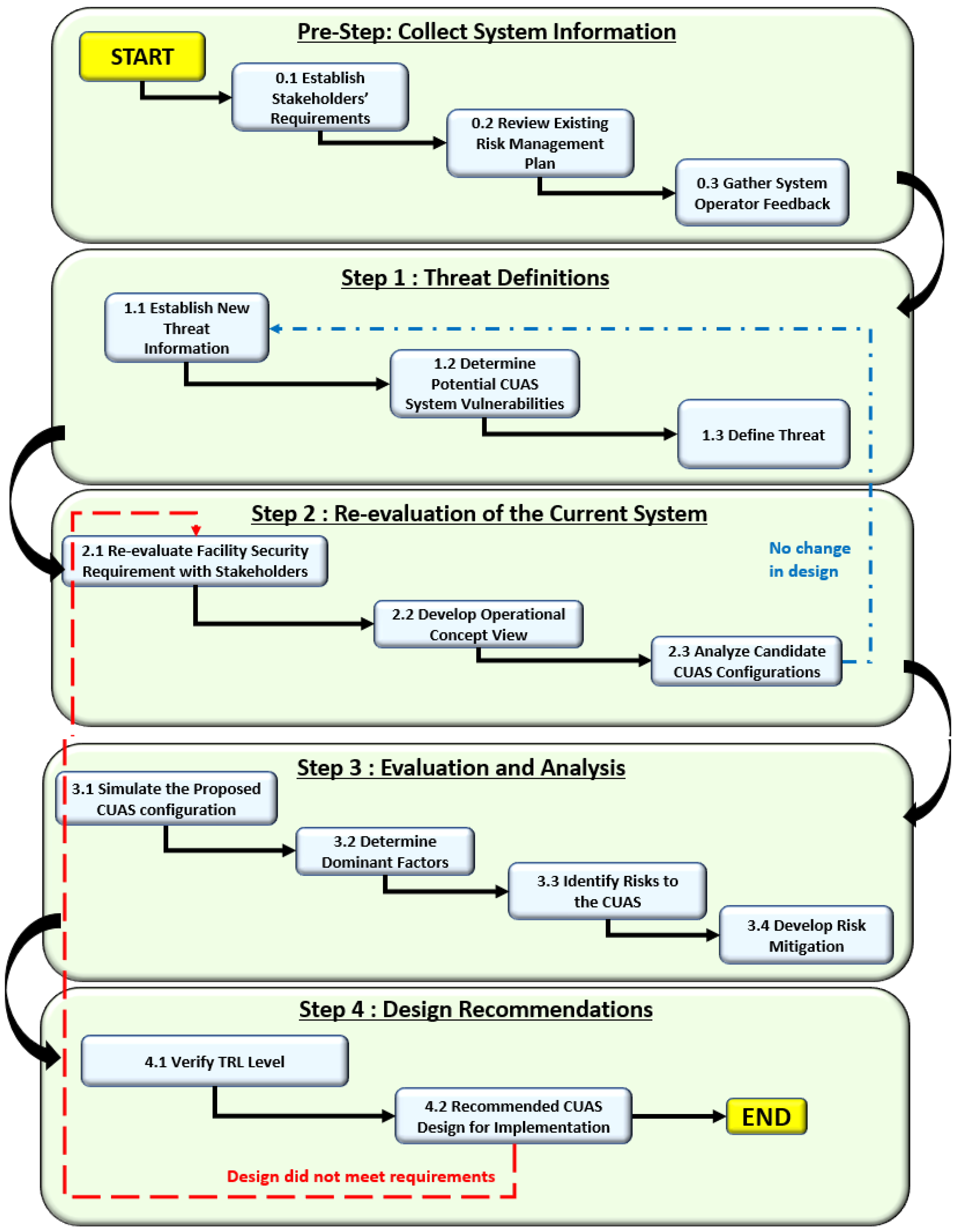


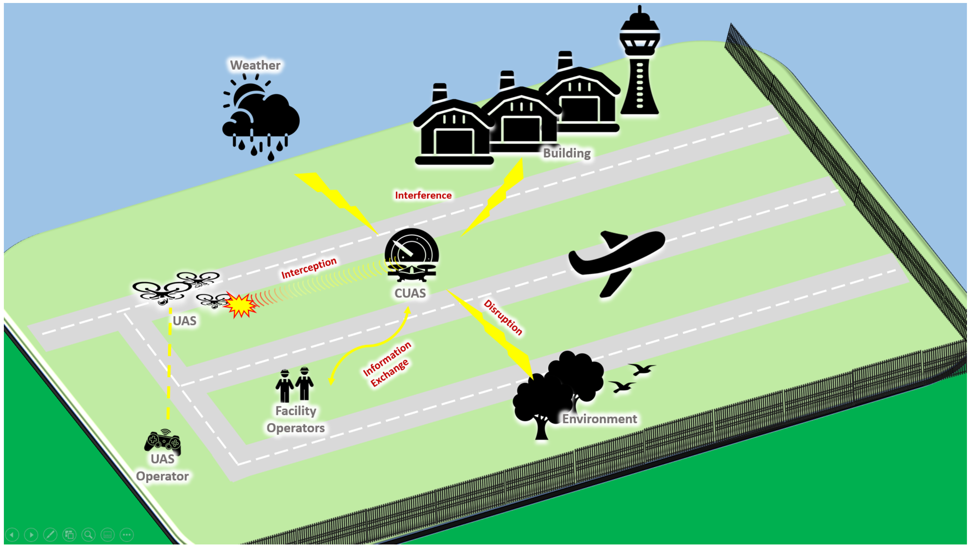
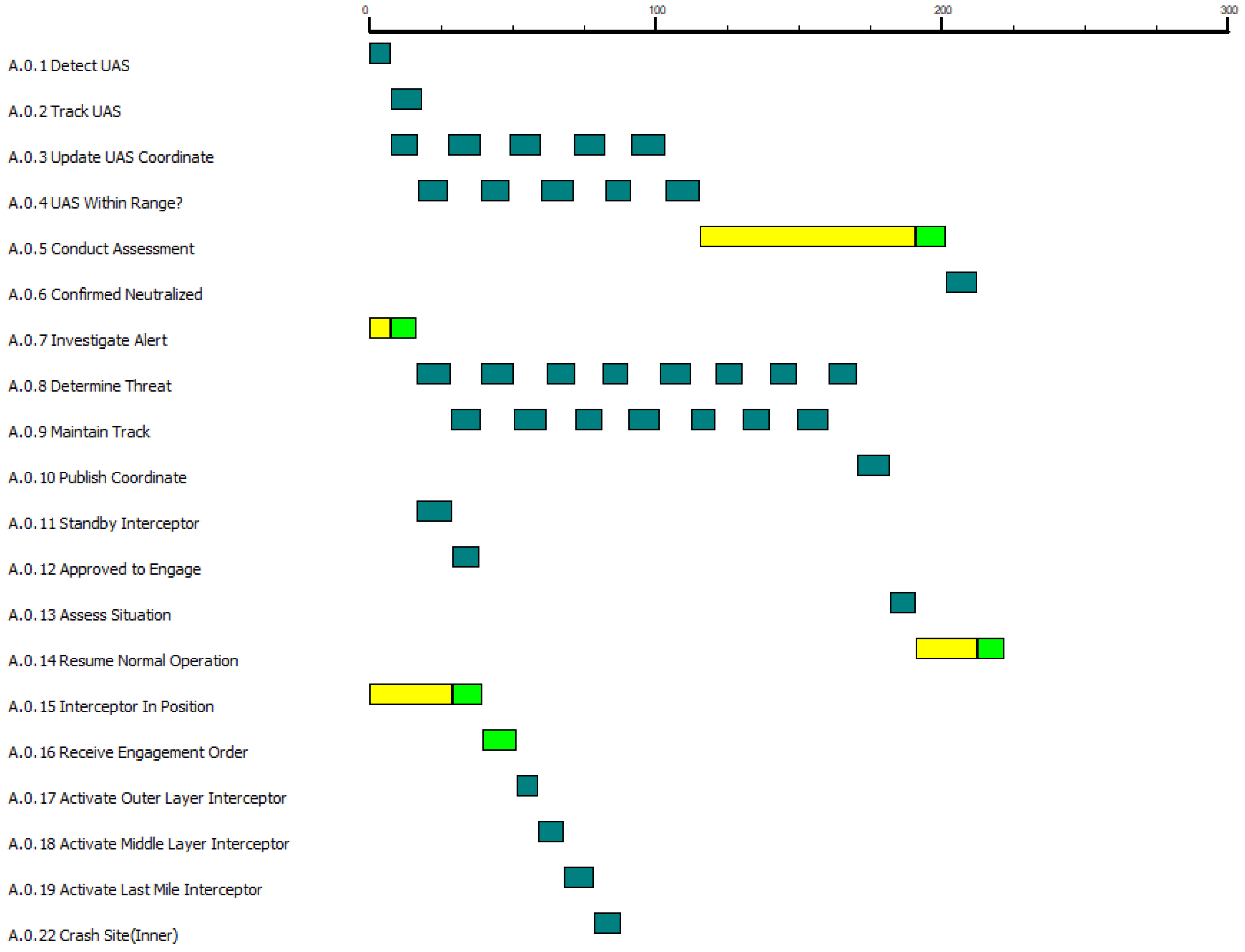