Abstract
This paper presents the robust synchronization problem of a 3D chaotic system by using the active control technique. Based on the Gershgorin theorem and Routh-Hurwitz criterion, sufficient algebraic conditions are derived to design a linear controller gain matrix. The conditions are then applied for the robust stability of the synchronization error dynamics in the presence of an unknown bounded smooth external disturbance. The proposed active control strategy with a suitable computation of the linear controller gain matrix is simple in design and establishes fast convergence rates of the synchronization error signals. Numerical simulation results further verified the analytical results.
1. Introduction
For the last two decades, chaos synchronization has been widely explored in various research fields [1,2,3]. The ever present demand for secure communication is one of the foremost form of motivation for studying chaos synchronization [4,5,6]. Various linear and nonlinear control techniques have been developed to carry out synchronization behavior. Some of these include, adaptive control [7], linear error state feedback control [8], backstepping method [9], active control [10], sliding mode control [11], and nonlinear control [12] are worth citing here, among others.
Recently, active control strategies have received considerable interest among many researchers due to the simple implementation for chaotic synchronization. Using the active control algorithm, Agiza and Yaseen [13] presented the synchronization of two identical Rossler and two identical Chen chaotic systems. Lei et al. [14] reported the synchronization problem of two identical nonlinear gyros using the active control based on the Routh-Hurwitz criterion and Lyapunov stability theory. Ucar et al. [15] utilized the active control technique for chaos synchronization in RCL-shunted Josephson function. Njah and Vincent [16] investigated the synchronization and anti-synchronization of two identical extended BVP chaotic oscillators by using the generalized active control method. Based on the Routh-Hurwitz criterion and Lyapunov stability theory and using the active control strategy, Shahzad and Ahmad [17] showed an experimental study of synchronization and anti-synchronization for the spin orbit problem of Enceladus. Recently, Ahmad et al. [10], addressed the synchronization problem of two identical and two non-identical chaotic systems using the active control technique based on the Lyapunov stability theory. A modification has been made based on the Lyapunov stability theory [18] for the globally, asymptotically-stable synchronization.
However, the finding of these studies [10,13,14,15,16,17] guarantee the asymptotic stability of the resulting synchronization error dynamics by allocating negative eigenvalues of the coefficient matrix in the closed-loop system that simply obeys the Routh-Hurwitz criterion. Convergence rates of the synchronization error signals depend on the numeric values of the controller gain coefficients. In real-life applications, selecting high controller gain coefficients may lead to automatic signal saturations and the two coupled chaotic/hyperchaotic systems may lose synchronization stability completely. In fact, the above notable results [10,13,14,15,16,17] affect each other mutually and need a systematic approach to compute suitable linear controller gains. In addition, the chaotic systems are considered free of the unknown external disturbance.
In this article, based on the Gershgorin theorem [19] and Routh-Hurwitz criterion [20] and using the active control strategy, a generalized approach is proposed to compute a suitable linear controller gain matrix that establishes globally asymptotical synchronization under the effect of unknown external disturbance.
There are three main aims for this paper. The first aim is to study the synchronization problem of a newly reported 3D chaotic system [21] in the presence of an unknown external disturbance. The second aim is to discuss the active control method for the synchronization of two identical and two non-identical 3D chaotic systems. The third aim is to derive analytically the sufficient algebraic conditions to compute a suitable linear control gain matrix that guarantees globally asymptotical stability of the closed-loop system. Two illustrative examples are given to verify the robustness and the performance of the proposed approach; complete synchronization between two identical chaotic systems [21], and the generalized synchronization between the chaotic system [21] and the Liu-Chen chaotic system [22].
The rest of the paper is organized as follows: In Section 2, the problem statement is given and derived the generic criterion to construct a proper linear control gain matrix using the active control technique. In Section 3, description of a new 3D chaotic system [21] is briefly described and synchronization behavior of two identical chaotic systems [21] are given, followed by the analysis of synchronization between the new chaotic and the Liu-Chen chaotic systems in Section 4. The paper concludes in Section 5.
2. Problem Statement and a Theory for the Proposed Active Control Strategy
Let us consider a drive-response chaotic system synchronization scheme is described as follows:
where are the state vectors, are the nonlinear bounded smooth functions, and are the matrices of the chaotic drive and response systems parameters alternatively, are the vectors of the unknown bounded smooth external disturbances present in the drive and response systems, respectively and is the control input to be designed later.
Assumption 1.
It is assumed that the unknown external disturbances are norm-bounded [2].
where are positive constants.
Definition 1.
Let us define the synchronization error system as follows:
where represents the Euclidean norm in .
From the drive-response system arrangement Equation (1), it follows that:
where is the function of residual terms and is the (n × n) coefficient matrix of the error system Equation (4) [23].
If , then, are the states of two identical chaotic systems and if, , then, are the states of two different chaotic systems.
Corollary 1.
The two coupled chaotic systems Equation (1) are globally asymptotically synchronized in a sense:
The chaotic synchronization problem can be considered as a stabilization of the synchronization error at the origin by a suitable controller . This means that the controller directs the synchronization error trajectories to the origin for all , where is the time of control activation.
Active Controller Design
Theorem 1.
Let us define the following control function:
where is the sub-controller function with is a linear controller gain matrix that regulates the strength of the feedback controller into the response system.
Proof of Theorem 1.
It is assumed that the parameters of the drive and response systems are available and measurable. Using systems of Equations (4) and (6) that yields:
.
At this stage, the problem is reduced to show that the matrix of the closed-loop Equation (7) is Hurwitz.
Lemma 1.
The necessary and sufficient condition for the matrix of the closed-loop system Equation (7) being a Hurwitz matrix, if all eigenvalues of the matrix have negative real parts, then, the zero solution of the closed-loop system Equation (7) is globally asymptotically stable.
The proof for Lemma 1 can be found in [20].
Now, we state the main theorem.
Theorem 2.
The coefficient matrix of the closed-loop system Equation (7) is Hurwitz if the linear controller gain matrix is design such that coefficient matrix in Equation (7) satisfies the following two conditions:
Then, the closed-loop system Equation (7) is globally asymptotically stable.
Proof of Theorem 2.
Let us assumed that be a real symmetric matrix. Further, it is assumed that the coefficients of the feedback controller gain matrix are designed such that the system matrix satisfies the two conditions of the Theorem 2. Then, the matrix is a strictly diagonally dominant (SDD) non-singular matrix. By the Gershgorin theorem [19], if a matrix is SDD and all its diagonal elements are negative, then, every eigenvalue of the system matrix is also negative. Thus, by the Routh-Hurwitz criterion [20], the matrix is Hurwitz. Hence, by the linear control theory [20], the closed-loop system Equation (7) is globally asymptotically stable. This implies that the two coupled chaotic systems Equation (1) are globally asymptotical synchronized.
3. Identical Chaos Synchronization
3.1. Description of the New 3D Chaotic System
Recently, a new 3D chaotic system is reported [21], which is contructed by replacing a constant parameter e with a switching function in Qi four-wing chaotic attractor and generated an eight-wing chaotic attractor. The system of differential equations describing the chaotic system [21] are given as follows:
where are the state vectors and are all real positive system parameters and , is a parameter function with as the switching frequency, , and are the constant parameters which takes values within a certain range. It has been investigated [21] that when , originally the system [21] shows a four-wing chaotic attractor and when and λ = 10, the parameter function with , then, the new system displays an eight-wing chaotic attractor (mother butterfly) and the new four-wing attractor (Baby butterfly) is very close to the origin [21]. The proposed eight-wing chaotic attractor has a complex dynamics and topologically different structure than the original Qi four-wing chaotic attractor as shown in Figure 1. Due to the complex properties of the system Equation (9), it is now significant to synchronize the chaotic system [21] for further research purposes on theoretical ground in order to implement it for hybrid image encryption, secure communications, and chaotic masking, etc.

Figure 1.
(a) 2D phase portrait of the new 3D chaotic system in XY-space; (b) XZ-space; and (c) YZ-space. Note. For our own simplicity, we will use for alternatively.
3.2. Problem Statement
In this sub-section of the paper, we briefly describe the identical synchronization scheme for the two coupled chaotic systems [21]. The drive chaotic system Equation (9) with three state variables denoted by the subscript 1 drives the response chaotic system having identical equations denoted by the subscript 2. Although, the initial conditions of the two systems are different. The two coupled chaotic systems [21] are described in a drive-response system synchronization scheme as follows:
where are the state vectors and are the positive parameters of the drive and response systems Equations (10) alternatively, as the control input injected to the response system, and are the vectors of unknown bounded smooth external disturbances present in the drive and response systems respectively.
Definition 2.
The error dynamical system for the synchronization scheme Equation (10) is described as follows:
.
Theorem 3.
Let us define the following active control functions:
Then, the two coupled identical chaotic systems Equation (10) are globally asymptotically synchronized.
Proof of Theorem 3.
It is assumed that all the variables and parameters of the two chaotic systems Equation (10) are available and measureable. Using systems of Equations (11) and (12), that yields:
where .
Re-write system of Equation (13) as follows:
where
The closed-loop system Equation (15) to be controlled is a linear system with control input as a function of alternatively, where the constants are the linear controller gains. As long as these controller gains stabilize the closed-loop system Equation (15), the converge to zero as time goes to infinity [16], then, the zero solution of the closed-loop system Equation (15) is obvious. This implies that the two coupled identical chaotic systems Equation (10) are globally asymptotically synchronized.
At this stage, the problem is reduced to show that the matrix of the closed-loop system Equation (15) is Hurwitz.
Corollary 2.
If the coefficient matrix in Equation (17) of the closed-loop system Equation (15) is Hurwitz, then the zero solution of the error system Equation (15) is globally asymptotically stable.
Theorem 4.
The matrix is Hurwitz, if the linear controller gain matrix is constructed such that the coefficient matrix in Equation (17) satisfies the following two conditions:
Proof of Theorem 4.
The controller Equation (12) is associated to the feedback controller gain matrix so that the design of is to make all eigenvalues of the coefficient matrix of the closed-loop system Equation (15) are in the open left-half of the complex plane. For the particular choice of the gain coefficients, which satisfies the conditions Equation (18) are selected as follows:
With this specific choice of the controller gains and considering: , the closed-loop system Equation (15) yields:
Thus, by the Routh-Hurwitz criterion, the matrix is Hurwitz. This proves that the closed-loop system Equation (15) is globally asymptotically stable. Consequently Theorem 4 and Corollary 2 are obvious. Hence Theorem 3 is proved.
3.3. Numerical Simulation and Discussion
Numerical simulation results are furnished to validate the advantages and effectiveness of the proposed approach by using Mathematica 10. The parameters for the chaotic system [21] are set as with initial values of the state variables of the drive and response systems being chosen as respectively. In the simulation, the following external disturbances are applied to the drive and response systems respectively.
Subsequently, , that satisfies the assumption 1.
For the identical chaotic systems [21], the time series of the state vectors of the synchronized and unsynchronized trajectories are depicted in Figure 2, Figure 3 and Figure 4. The state trajectories of the drive system converged to the state trajectories of the response system under the control action Equation (12).
The time series of the error system Equation (11) for identical synchronization are shown in Figure 5. As expected, one can notice the smoothness of the synchronized error signals while converging to the zero state quickly, when the controllers are activated at . This demonstrates the robustness and performance of the control action Equation (12) for the complete synchronization under the effect of unknown external disturbance.
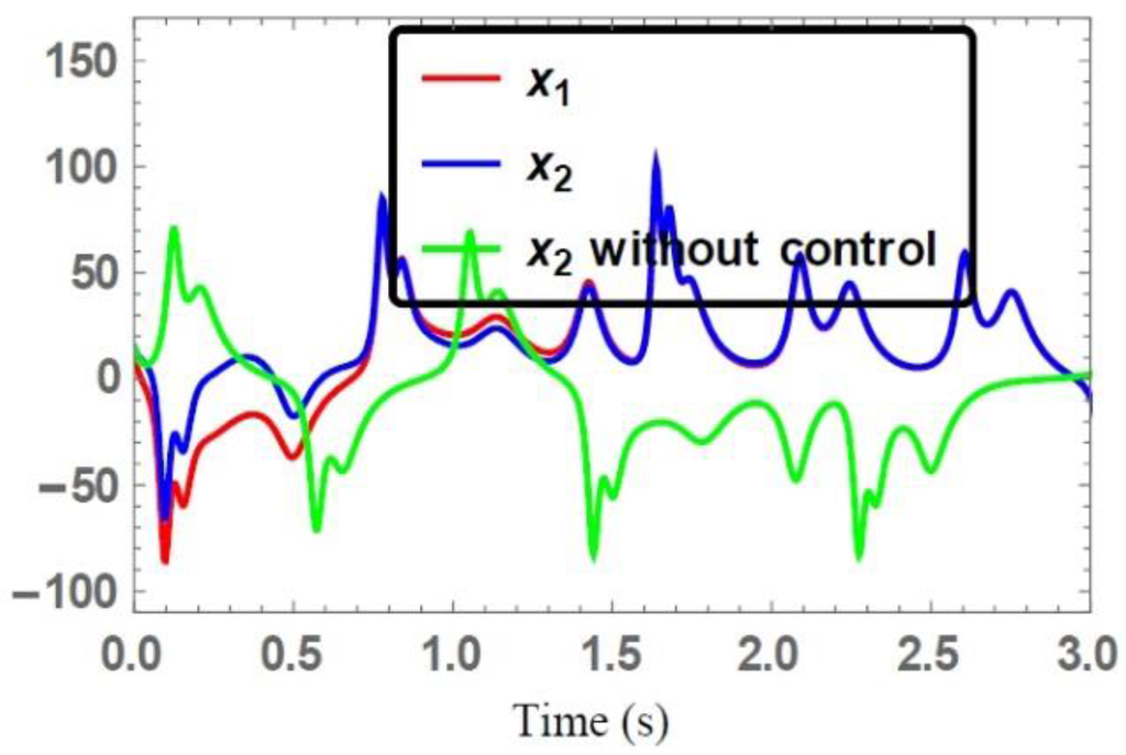
Figure 2.
Time series of the state trajectories .
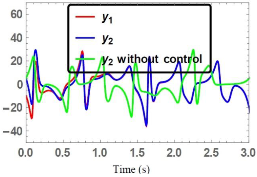
Figure 3.
Time series of the state trajectories .
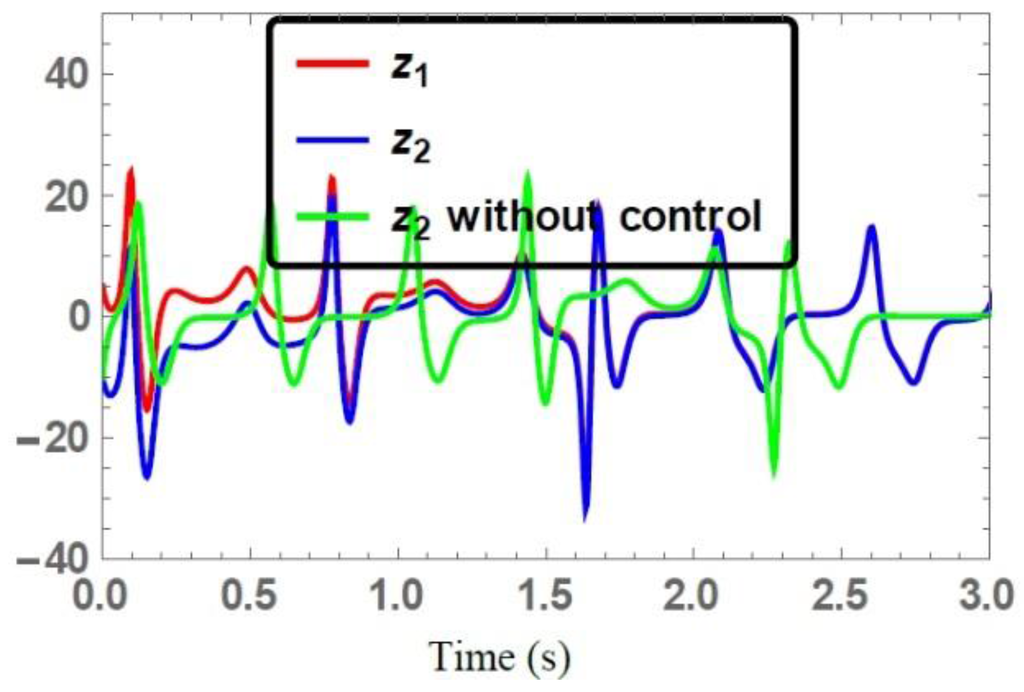
Figure 4.
Time series of the state trajectories .
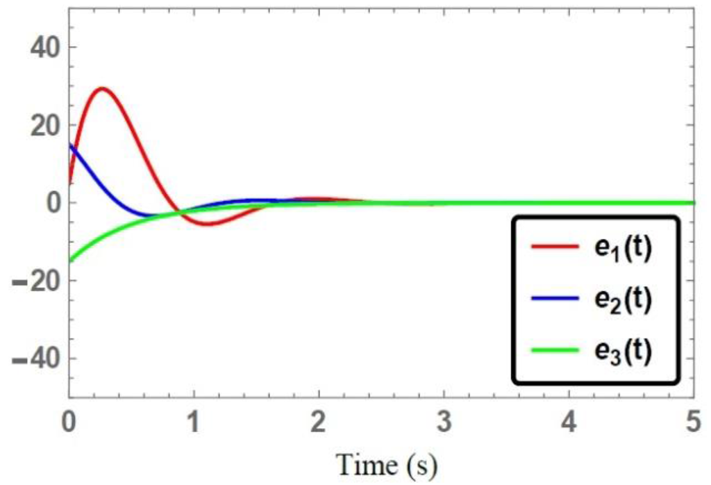
Figure 5.
Time series of the controlled synchronization error system Equation (11).
4. Non-Identical Synchronization
4.1. Problem Formulation
To study the generalized synchronization problem for the chaotic system [21], it is assumed that the chaotic system [21] drives the Liu-Chen chaotic system [22]. Thus, the drive-response system synchronization scheme is described as follows:
where are the corresponding state vectors, and are the parameters of the drive and response systems respectively, are the vectors of unknown bounded smooth external disturbances present in the drive and response systems Equation (22) respectively, and as the active controller that is to be designed yet.
Definition 3.
The error dynamical system for the synchronization scheme Equation (22) is be described as follows:
Theorem 5.
Let us define the following active control functions:
Then, the two coupled non-identical chaotic systems Equation (22) are globally asymptotically synchronized.
Proof of Theorem 5.
It is assumed that all the variables and parameters of the two systems Equation (22) are available and measureable. Using systems of Equations (23) and (24), that yields:
where .
Re-writing the system of Equation (25) as follows:
where
Theorem 6.
The matrix is Hurwitz, if the feedback controller gain matrix is constructed such that the coefficient matrix Equation (28) of the closed-loop system Equation (26) satisfies the following two conditions:
Proof of Theorem 6.
For the particular choice of the linear controller gains which satisfies the conditions Equation (28) are selected as follows:
With this specific selection of the linear controller gains and considering: , the closed-loop system Equation (26) yields:
This completes the proof.
4.2. Simulation Studies
The parameters for the chaotic system [21] and Liu-Chen system [22] are set as with initial values of the drive [21] and response [22] systems being chosen as and alternatively. In the simulation, the following bounded smooth disturbances are applied to the drive and response systems, respectively:
Accordingly, .
For the non-identical chaotic systems [21,22], the time series of the state vectors of the synchronized and unsynchronized trajectories are illustrated in Figure 6, Figure 7 and Figure 8. These figures demonstrated that the state trajectories of the response system converged to that state trajectories of the drive system under the synthesized control action Equation (24), while the uncontrolled state trajectories of the response system are completely different from the drive system state trajectories. Time series of the error system Equation (23) to the zero state are depicted in Figure 9. One can notice the smoothness of the synchronized error trajectories while converging to the zero state with fast converging rates, which illustrates the performance of the control action Equation (24) for non-identical synchronization. This feature shows that the investigated controllers are robust to the accidental parameters mismatch and unknown external disturbances in the transmitter and receiver.
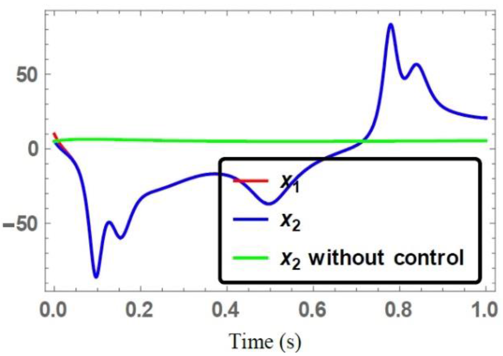
Figure 6.
Time series of the state trajectories .
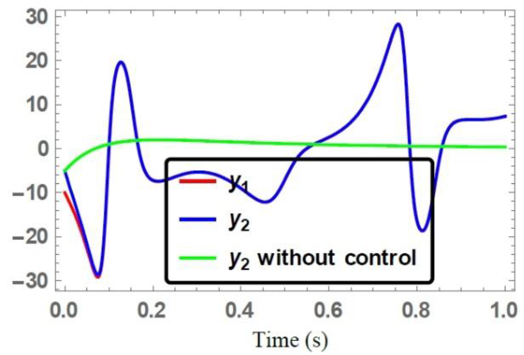
Figure 7.
Time series of the state trajectories .
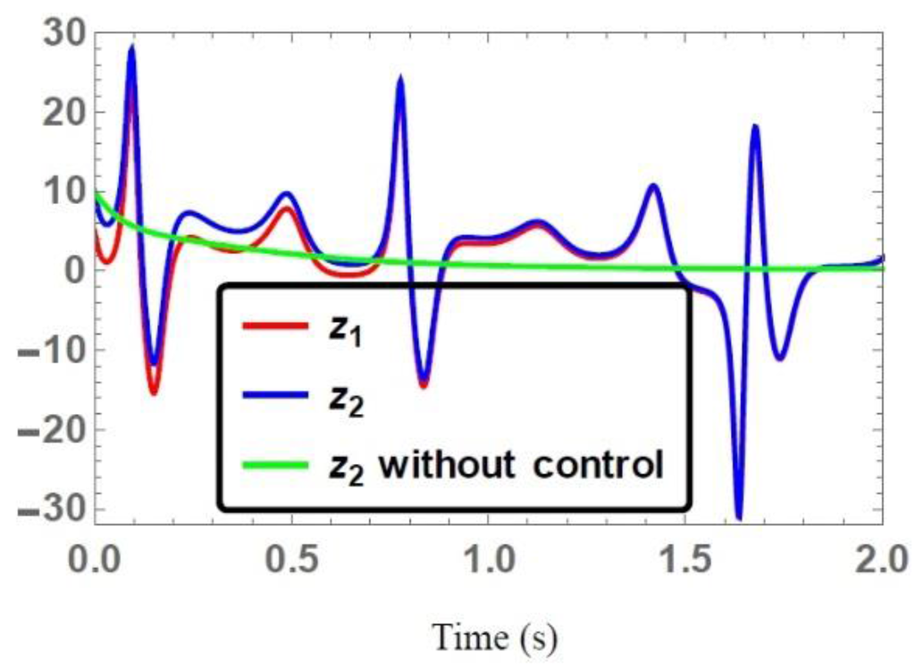
Figure 8.
Time series of the state trajectories .
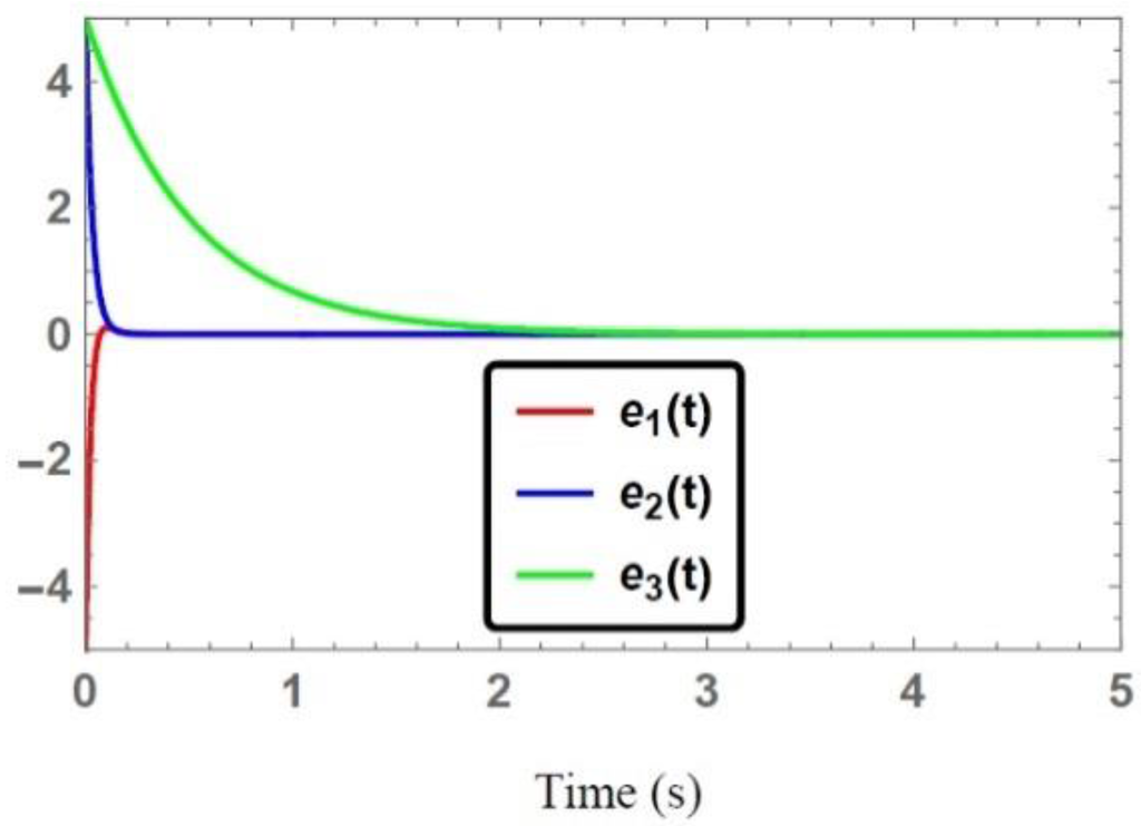
Figure 9.
Time series of the controlled synchronization error system Equation (26).
5. Conclusions
The robust synchronization problem of two identical and two non-identical chaotic systems has been investigated. Based on the Gershgorin theorem and Routh-Hurwitz criterion and using the active control strategy, sufficient conditions are derived to construct a suitable linear gain matrix that established the globally asymptotical synchronization under the effect of an unknown external disturbance. Numerical simulation results show that the proposed approach works very well and can be applied to a class of chaotic as well as hyperchaotic systems successfully.
In comparison with some published related works, there are three main advantages of the proposed approach which are summarized as follows.
- (a)
- The synchronization speed is fast as well as the amplitude of the oscillations is smaller.
- (b)
- In the proposed active synchronization control approach, the eigenvalues of the coefficient matrix of the closed-loop system can be adjusted to have a desirable synchronization time.
- (c)
- Most of the chaotic systems in real practical applications have different structures, thus, we believe that the proposed active control approach will be a helpful tool in synchronizing a class of chaotic/hyperchaotic systems.
Acknowledgments
The authors would like to express their gratitude to the honorable reviewers who suggested many worthwhile changes to improve the work of this manuscript.
Author Contributions
Azizan Bin Saaban performed the literature review and proposed the problem.
Adyda Binti Ibrahin and Israr Ahmad performed the analytical analysis and wrote the paper. M. Shahzad performed the numerical simulations and revised the manuscript.
Conflicts of Interest
The authors declare no conflict of interest.
References
- Tunik, A.A.; Galaguz, T.A. Robust stabilization and nominal performance of the flight control system for small UAV. Appl. Comput. Math. 2004, 3, 34–45. [Google Scholar]
- Koofigar, H.R.; Sheikholeslam, F.; Hosseinnia, S. Robust adaptive synchronization for a general class of uncertain chaotic systems with application to Chua’s Circuit. CHAOS 2011, 21, 0431341–0431349. [Google Scholar] [CrossRef] [PubMed]
- Ge, A.M.; Yang, C.H. The generalized synchronization of a Quantum-CNN chaotic oscillators with different orders. Chaos Solitons Fractals 2006, 35, 980–990. [Google Scholar] [CrossRef]
- Hammami, S. State feedback-based secure image cryptosystem hyperchaotic synchronization. ISA Transit. 2014. [Google Scholar] [CrossRef] [PubMed]
- Li, Y.; Liu, X.; Chen, G.; Liao, X. A new hyperchaotic Lorenz-type system: Generation, analysis, and implementation. Int. J. Circuit Theory Appl. 2010, 39, 865–879. [Google Scholar] [CrossRef]
- Wu, X.; Zhu, C.; Kan, H. An improved secure communication scheme based passive synchronization of hyperchaotic complex nonlinear system. Appl. Math. Comput. 2015, 252, 201–214. [Google Scholar] [CrossRef]
- Ahmad, I.; Saaban, A.; Ibrahim, A.; Al-Hadhrami, S.; Shahzad, M.; Al-Mahrouqi, S.H. A Research on Adaptive Control to Stabilize and Synchronize a Hyperchaotic System with Uncertain Parameters. Int. J. Optim. Control Theor. Appl. IJOCTA 2015, 5, 51–62. [Google Scholar] [CrossRef]
- Chen, H. Global Chaos Synchronization of Chaotic systems via Linear balanced feedback control. Appl. Math. Comput. 2007, 186, 923–931. [Google Scholar] [CrossRef]
- Ojo, K.S.; Njah, A.N.; Ogunjo, S. Comparison of backstepping and modified active control in projective synchronization of chaos in an extended Bonhoffer-van der Pol Oscillator. Pranama J. Phys. 2013, 80, 825–835. [Google Scholar] [CrossRef]
- Ahmad, I.; Saaban, A.; Ibrahim, A.; Shazad, M. Global Chaos Synchronization of New Chaotic system Using Linear Active Control. Complexity 2014, 21, 379–386. [Google Scholar] [CrossRef]
- Akbar, M.; Ozguner, U. Decentralization Sliding Mode Control Design using overlapping decomposition. Autometica 2002, 38, 1713–1718. [Google Scholar] [CrossRef]
- Ahmad, I.; Saaban, A.; Ibrahim, A.; Shazad, M. A Research on the Synchronization of Two Novel Chaotic Systems Based on a Nonlinear Control algorithm. Eng. Technol. Appl. Sci. Res. 2015, 5, 739–747. [Google Scholar]
- Agiza, H.N.; Yassen, M.T. Synchronization of Rossler and Chen Chaotic Dynamical Systems using Active Control. Phys. Lett. A 2001, 278, 191–197. [Google Scholar] [CrossRef]
- Lei, Y.; Xu, W.; Zheng, H. Synchronization of two chaotic nonlinear gyros using active control. Phys. Lett. A 2005, 343, 153–158. [Google Scholar] [CrossRef]
- Ucar, A.; Lonngren, K.E.; Bai, E.W. Chaos synchronization in RCL-shunted Josephson junction via active control. Chaos Solitons Fractals 2007, 31, 105–111. [Google Scholar] [CrossRef]
- Njah, A.N.; Vincent, U.E. Synchronization and anti-synchronization of chaos in an extended Bonho ffer-van der Pol Oscillator using Active control. J. Sound Vib. 2009, 319, 41–49. [Google Scholar] [CrossRef]
- Shahzad, M.; Ahmad, I. Experimental study of synchronization & Antisynchronization for spin orbit problem of Enceladus, International. J. Control Sci. Eng. 2013, 3, 41–47. [Google Scholar]
- Khalil, H.K. Non Linear Systems, 3rd ed.; Prentice Hall: Upper Saddle River, NJ, USA, 2002. [Google Scholar]
- Scott, D.S. On the Accuracy of the Gershgorin Circle Theorem for Bounding the Spread of a Real Symmetric Matrix. Linear Algebra Appl. 1985, 65, 147–155. [Google Scholar] [CrossRef]
- Dorf, R.C.; Bishop, R.H. Modern Control Systems, 9th ed.; Princeton Hall: Upper Saddle River, NJ, USA, 2001. [Google Scholar]
- Qi, G.; Wang, Z.; Guo, Y. Generation of an eight-wing chaotic attractor from QI-3D four-wing chaotic system. Int. J. Bifurc. Chaos. 2012, 22. [Google Scholar] [CrossRef]
- Liu, W.; Chen, G. Can a three-dimensional smooth autonomous quadratic chaotic system generate a four-scroll attractor. Int. J. Bifurc. Chaos. 2004, 14, 1395–1403. [Google Scholar] [CrossRef]
- Ling, L.U.; Guo, Z.A.; Chao, Z. Synchronization between two different chaotic systems with nonlinear feedback control. Chin. Phys. 2007, 16, 1603–1607. [Google Scholar] [CrossRef]
© 2015 by the authors; licensee MDPI, Basel, Switzerland. This article is an open access article distributed under the terms and conditions of the Creative Commons by Attribution (CC-BY) license (http://creativecommons.org/licenses/by/4.0/).