Article

Semantically Valid Integration of Development Processes and Toolchains

1
Quality Assurance VW PKW, Volkswagen AG, 38436 Wolfsburg, Germany
2
Department of Computer Sciences, Darmstadt University of Applied Sciences, 64295 Darmstadt, Germany
3
Institute of Management & Information Systems, FOM University of Applied Sciences, 45127 Essen, Germany
4
Institute for Software and Systems Engineering, Technical University of Clausthal, 38678 Clausthal-Zellerfeld, Germany
*
Author to whom correspondence should be addressed.
Current address: Joachim Schramm, Ruebekamp 4a, 38685 Langelsheim, Germany.
Systems 2022, 10(2), 40; https://doi.org/10.3390/systems10020040
Submission received: 1 December 2021 / Revised: 16 March 2022 / Accepted: 17 March 2022 / Published: 22 March 2022
(This article belongs to the Section Systems Engineering)

Abstract

:
As an indispensable component of today’s world economy and an increasing success factor in production and other processes, as well as products, software needs to handle a growing number of specific requirements and influencing factors that are driven by globalization. Two common success factors in the domain of Software Systems Engineering are standardized software development processes and process-supported toolchains. Development processes should be formally integrated with toolchains. The sequence and the results of toolchains must also be validated with the specifications of the development process on several levels. The outcome of a conceptual deductive analysis is that there is neither a formal general mapping nor a generally accepted validation mechanism for the challenges that such an integrated concept faces. To close this research gap, this paper focuses on the core issue of the integration of development processes and toolchains in order to create benefits for modeling and automatization in the domain of systems engineering. Therefore, it describes a self-developed integration approach related to the recently introduced prototypical technical implementation TOPWATER. A unified metamodel specifies how processes and toolchains are linked by a general mapping mechanism that considers test options for the structural, content, and semantic levels.

1. Introduction

As an indispensable component of today’s economy, software is an increasing success factor for both production and working processes. Specific requirements and influencing factors—driven by, for instance, globalization—demand more attention and add more complexity to software development and software products. In order to consider quality, cost, and time constraints while developing complex software, companies tend to replicate established success strategies, with both positive and negative effects [1,2].
Two common success factors in the domain of Software Systems Engineering are standardized software development processes and process-supported toolchains [3]. The introduction and application of at least one of these success factors has a positive effect on a company’s success. The hypothesis that potentially high synergy effects arise may be accepted if these two success factors are introduced, applied, and validly integrated.
In the context of large development projects, contributors especially need to know the formative conditions (who, when, and what to do) and in which quality a document or product needs to be available. Processes should exactly deliver such contributions to increase the success of a project while minimizing risks and total expenses [4].
A process may be defined as a “set of interrelated or interacting activities which transforms inputs into outputs” [5]. All software development steps, including boundaries and artifacts, such as input and output documents or products, quality criteria, and management aspects and roles, are specified in detail in software development processes. They are implemented in companies with the aim of conducting software development projects in a reliable and repeatable way. In the course of time, this leads to an increase in quality and the opportunity to save costs and shorten project durations. In this context, the main driver consists of increasing the efficiency of the project team members in order to make them spend less time on recurring development tasks [6,7,8].
However, many standardized development processes only serve as general reference models [4,9], and each company adapts them to their particular requirements. Inadequate implementation does not usually influence the common development process, leading to discrepancies between newly defined development processes and actually executed activities and their subsequent outcomes [10]; thus, the intended benefits from new processes are mostly lost.
Employees must, therefore, receive support in order to learn which tools best serve their efficient performance. That is exactly the aim of toolchains, whose components (known as tools) are usually computer programs. Software developers use them to create, test, and maintain other software programs and applications, as well as for other supportive tasks [11]. Toolchains consist of at least two associated tools that interchange data and share a common goal, and they are used in order to efficiently carry out repetitive tasks. This leads to significant cost savings and reduced project duration [12].
If toolchains are viewed in isolation, it is a challenge to check whether the tool sequence, as well as the quality and quantity of the created results, follows a process reference model, as these are general and toolchains are specific.
Development processes should, therefore, not only be formally integrated with toolchains, but the sequence and the results of toolchains must also be validated with the specifications of the development process on several levels; however, there is neither a formal general mapping nor validation mechanism to deal with the challenges of such an integrated concept.
As an example, consider a system architecture created with one or more tools in a toolchain. The absence of the mandatory chapter interface overview from the system architecture poses a problem on both the structural and content levels. If it is created by a toolchain, but there are none or not all interfaces listed in this chapter, the problem is on the content level. If tools have a different understanding of a concept (e.g., interface), this indicates a problem on the semantic level.
If such problems are solved with the successful integration of development processes and toolchains, not only the advantages of both development processes and toolchains remain, but the individual disadvantages also disappear. Finally, a major constraint for the integration is that development processes need to be understood as leading information on how toolchains should be oriented.
Therefore, this paper focuses on the core issue of the integration of development processes and toolchains in order to create benefits for modeling and automatization in the domain of systems engineering. The key result will be a self-developed approach for such an integration (see Section 3.1.2). It is, first of all, a metamodel-based general mapping mechanism, and it presents a description and test options for the structural, content, and semantic levels.
The fulfillment of all of these characteristics is called “semantically valid integration of development processes and toolchains”. Following the introduction of the prototypical technical implementation TOPWATER by Schramm et al. [13], in this article, we provide more detailed insights related to the concepts behind it. Related work and the current state of research are discussed in the following section (Materials and Methods); then, we go into details about the self-developed solution approach and show how to check the syntax of process and tool mappings (Results). This is followed by the fourth section (Discussion), which is dedicated to an evaluation of the proposed method, as well as conclusions and ideas for subsequent research.

2. Materials and Methods

2.1. Related Work and Contribution

The following section first discusses related work covering process engineering and enactment approaches. After that, tools and toolchain solutions are discussed before integration approaches are presented. Finally, this related work leads to the research gap and contribution. Instead of a systematic literature analysis, the method applied in this paper is more focused on a conceptual deductive analysis.

2.1.1. Process Engineering and Enactment Approaches

In the following section, we present related work covering process engineering and enactment approaches based on formal process metamodels and process descriptions, non-formal process descriptions being beyond the focus of our study. Enactment means here to execute or to “live” the process model. Instead of broader engineering lifecycles focused on systems, we place an emphasis on processes, artifacts, and toolchains. Thus, we do not follow a holistic approach and concentrate only on the processes in engineering life cycles. The approaches are analyzed according to how far they can contribute to the solution concept of this work.
Schramm et al. [10] previously proposed a holistic view of artifacts and activities in the process engineering lifecycle, where different recent contributions on formal process models and descriptions, metamodels, and support in executing processes were reviewed. This holistic view contains compulsory elements for formal process models, which are used in the solution concept proposed in this work, too. The enactment can happen in various ways, such as a transformation of process models to allow process execution, document generation [14], or rule-based execution of processes using explicit modeling languages, e.g., Marvel [15].
In addition to the modeling and enactment of process models, validation plays an important part. For example, the combination of the open- and closed-world reasoning approach by Krisnadhi et al. [16] describes a quite simple way for ontology designers to model local closed-world aspects in their ontologies. They used a knowledge base established on descriptive logic and designated some predicates as closed by augmenting them with meta-information. Those predicates were considered minimized. Bergner [17] used this concept in his methodology for an ontology-driven product configuration process that covers both the definition and validation of the concepts and the subsequent configuration and hybrid validation of the product exemplars. “Hybrid” here means that the validation can be used according to the open-world assumption as well as according to the closed-world assumption. A kind of hybrid validation is also used in the solution presented in this paper (see Section 4.2).
In the literature, one can find several process modeling frameworks, e.g., the Eclipse Process Framework [18], the V-Modell XT Editor [19], or AutoFocus3 [20], which allow modeling and partially enacting and validating processes by means of a metamodel. The solution concept proposed in this paper uses a metamodel, too.

2.1.2. Tool and Toolchain Solutions

This subsection discusses tools and toolchain solutions. The approaches are analyzed as to how far they can contribute elements and functionality to the solution concept of this work.
Portillo-Rodríguez et al. [21] gave an overview of various tools used in globally distributed software development, identifying two main approaches, namely, open platforms, such as Eclipse [22], and commercial tools/toolchains, such as Microsoft’s Team Foundation Server [23] or Rational’s Team Concert [24]. Even if the last one usually contains interfaces that are usable by third-party developers, in general, these platforms are closed to a certain extent and also require high expenditure and infrastructure requirements. Different from them are open platforms such as Swordfish [25], agosense.symphony [26], ToolNet [27], or ModelBus [28], which provide only mechanisms for technical integration that usually need specific adapters in order to integrate the employed tools. Even so, the adapters used on both open and commercial platforms present certain dependencies on these, which often involve considerable effort and costs. The Software Platform for Integration of Engineering and Things, known as SPRINT [29], was conceived for providing a unified view on the various parts of complex interdisciplinary systems. It managed to connect various domain-specific expert tools by allowing the design and transformation of data transferred between different tools. It employs the Open Service for Lifecycle Collaboration (OSLC) [30] for the actual connection in order to link development artifacts and to add semantics to them and their relations. Furthermore, the Validas Toolchain Analyzer [31] uses a model-based approach in order to document, validate, and qualify toolchains. The toolchain model contains, inter alia, toolchains, tools, artifacts, and use cases. This approach provides elements and functionality for the present work.

2.1.3. Integration Approaches

The last two subsections looked at related process engineering and enactment approaches that were separate from toolchain solutions, each for itself. This subsection will now present integration approaches between processes and toolchains. It is discussed if these related integration approaches solve the problem statement in the introduction. First, the kinds of integration are defined.
Wasserman [32] defined a successful integration between processes and tools in a toolchain as follows: “Process Integration provides a well-defined software development process spanning both the software lifecycle and the development project organization. Process Integration also defines how tools in a toolchain are used to carry out or `enact’ the integrated software process. The processes are traceable”. Such integration between processes and tools can be established on various levels:
  • Physical level: the means by which information is exchanged, e.g., Files, Web-Services, or API (application programming interface);
  • Syntactic level: a common structure of data, e.g., UML (Unified Modeling Language) model serialized as XMI (Extensible Markup Language Metadata Interchange);
  • Semantic level: a common understanding of the interpretation of the structured data, e.g., Software Component, Port, or Interface;
  • Content level: indicates the completeness of the data, control, and process output.
Solutions for continuous integration (CI), such as those of Jenkins [33], Cruise Control [34], or the Atlassian toolchain (e.g., Jira, Confluence, Bitbucket, Trello) [35], are agile representatives of often neglected but important aspects of process integration, especially on the semantic level, e.g., JIRA components versus software components. Amalfitano et al. [36] presented an industrial experience in the context of an international automotive company and developed an integration architecture based on Jenkins that integrates an application lifecycle management with the tools used to carry out a testing process conducted in the company. It allows the automatic generation of traceability links among the artifacts related to this process. They also mentioned as a future plan the intention of adapting their integration approach in further industrial contexts and different software processes involving different types of tools and artifacts, as well as the intention of evaluating additional quality attributes of the process.
Other software solutions in the field of process automation, such as Stages from Method Park [37] or Bizagi Suite [38], mainly cover the process integration, but apart from that, they neglect the semantic and content levels. So-called enterprise service buses, such as Modelplex [39] and comparable approaches, are only limited to the provision of basic mechanisms of technical integration. Finally, the most substantial issues with respect to this are the integration and related activities concerning functionalities in the meanings of base objects and workflows.

2.1.4. Research Gap and Contribution

Wassserman [32] not only defined process integration as an important issue for setting up toolchains, but also defined integration concerning the platform, presentation, data, and control. Adding various abstraction levels (physical, syntactic, content, and semantic) to the integration ones and mapping the presented approaches to this procedure, we obtained the scheme presented in Figure 1. It should be emphasized that there is no holistic approach available that covers all integration and abstraction levels. Several research gaps, especially in the fields of semantic and content abstraction, can be noted in Figure 1.
General mapping mechanism: Our approach aims to reduce the illustrated research gap by enabling the ability to create valid mappings between development processes and toolchains based on persisting mapping restrictions. The presented approach primarily integrates toolchains on the process integration level by taking all abstraction levels into account. The integration level process, however, also influences the control and data integration of the tools. The prototypical technical implementation TOPWATER [13] partially covers the Presentation integration within it, but should not share a common look and feel in the concrete tools from the user’s perspective. For the integration and sequence checking, a mapping mechanism based on a metamodel (see Section 3.1.2) was created, which enabled toolchains and processes to be linked with the help of so-called PTUseCases (ProcessTool-UseCase). This is based on the fact that development processes and toolchains each consist of artifacts, as the related work has shown. These may then be linked via higher-level use cases (PTUseCases) in order to achieve a specific business goal as well. In addition, mapping restrictions were identified that must be included in this concept to ensure only valid mappings (see Section 3.2). The concept is evaluated with a case study (see Section 4.1).
In order to perform a validity check of the physical, structural, semantic, and content requirements, we developed a method called hybrid validation (see Section 4.2) that focuses on divergence with regard to structure, content, and semantics affected by the current quality of the results of the toolchain and the quality specified by the development process.

3. Results

3.1. Solution Concept

To construct a solution concept, we employed the ideas of Model-Driven Development (MDD). Two basics are presented in the next subsection before the solution concept obtained by using these basics is offered. Classes of models are written in italics and begin with a capital letter.

3.1.1. Basics

Accountability Pattern (Fowler)

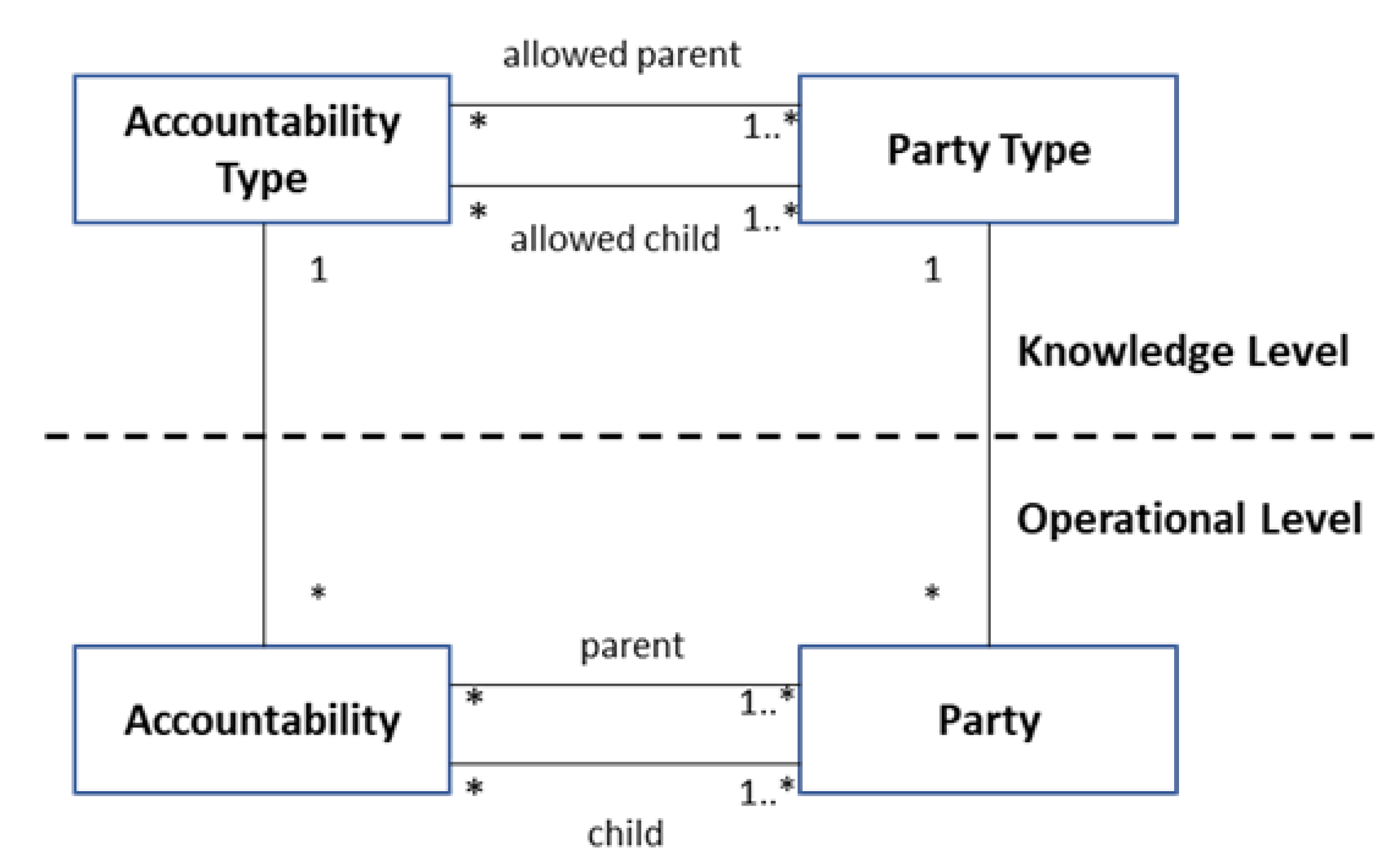
Fowler [40,41] designed an analysis pattern called Accountability, which represented a complex graph of relationships between Parties. The basic form of Accountability allows any combination of Parties with any Accountability Types. This can be handled by introducing a knowledge level and an operational one, as well as constraints to limit the way Accountabilities can be arranged with Parties.
Figure 2 shows the customized Accountability pattern for directed graphs [41]. Customization means the addition of both levels. The operational level consists of Accountability, the Party, and their interrelationships. The knowledge level consists of the Accountability Type, Party Type, and their interrelationships. The knowledge-level objects define the permitted instances of operational-level objects. Accountabilities can only be established between Parties according to corresponding Accountability Types and Party Types. Every day, the model records the events of the domain at the operational level [40]. Whenever an Accountability is created, it uses its type to validate the Accountability [41].

Linguistic vs. Ontological Metamodeling

Atkinson and Kühne [42,43] presented six requirements for an MDD-supporting infrastructure; in particular, they defined how the model’s elements represent real-world elements, including software artifacts and concepts for facilitating user-defined mappings from models to other artifacts, including code.
They identified four problems in the traditional infrastructure of Meta-Object-Facility (MOF) [44]—for instance, that there exists no explanation of how entities in the infrastructure are related to the real world. This and the two mentioned requirements are relevant to the concepts developed in this paper.
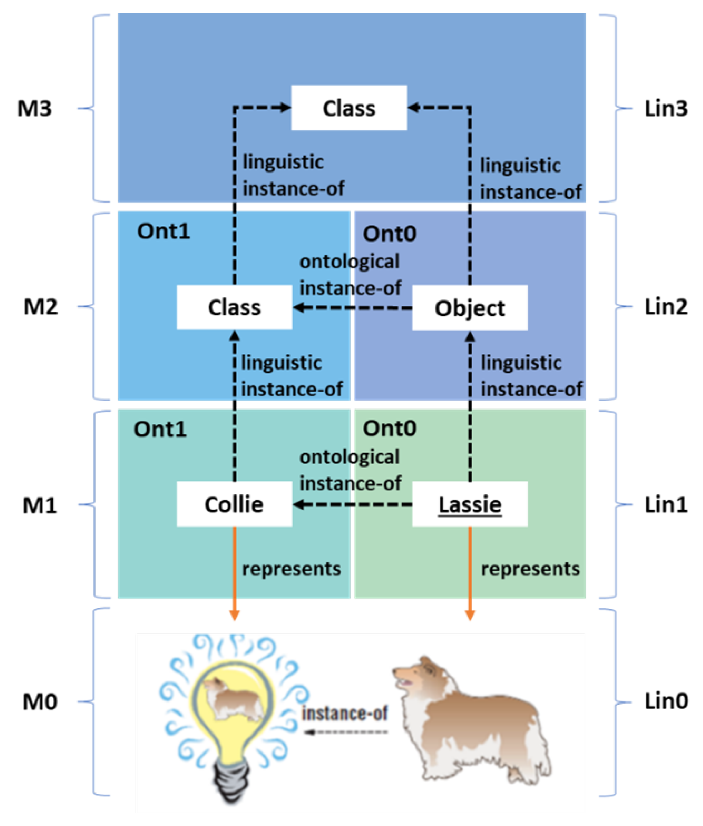
An MOF consists of four layers (M0: user data, M1: model, M2: metamodel, M3 meta-metamodel/MOF). Except for M3, each level is an instantiation of the next higher level. M0 contains the data objects created and changed by software tools. These objects are defined in M1 by the user concepts. On this level, domain data or process descriptions can be modeled. The structure of these models is defined in the metamodel M2, which is grounded by M3, which itself is defined to exclude more levels above it. MOFs make no difference between ontological or linguistic instantiation and no choice about their metalevels’ meaning [42].
This drawback and other flaws of MOFs motivated Atkinson and Kühne to develop two orthogonal dimensions of metamodeling with the intention of forming two distinct instantiation types. The first one is called linguistic instantiation and is used for language definition, while the second is ontological instantiation and is concerned with domain definition. Both dimensions occur simultaneously and have the ability to locate a model element with the language ontology space. The MOF layers are renamed Lin0–Lin3 to highlight their linguistic roles [42].
Figure 3 shows the linguistic and ontological metamodeling view. The linguistic instance-of relationships follows a vertical direction. Lin2 and Lin3 (linguistic levels) are the levels for language definition. The ontological instance-of relationships (horizontal) relate user concepts to their domain types, i.e., to a secondary role within one linguistic level. In Lin2/Ont0 (ontological level), the model element Object is an ontological instance of the model element Class in Lin2/Ont1. The model element Lassie on Lin1/Ont0 is an ontological instance of the model element Collie on the same linguistic level, but on a different ontological level, Ont1. Thus, Lassie is on a lower ontological level than Collie. On Lin0, the picture of the dog—the real Lassie—is an instance of the mental concept Collie (the Lightbulb). The user objects are model representatives of the real-world objects, and they inhabit the Lin1 level along with the types that they are ontological instances of. The real Lassie is represented the object Lassie. The instance-of is no longer used to characterize the real Lassie as an instance of Collie. User data are part of the real world, too. It is possible to have more than two levels of ontological instances Ont0 and Ont1, but for our study, these two should be enough [42].

3.1.2. Solution Concept by Using the Basics

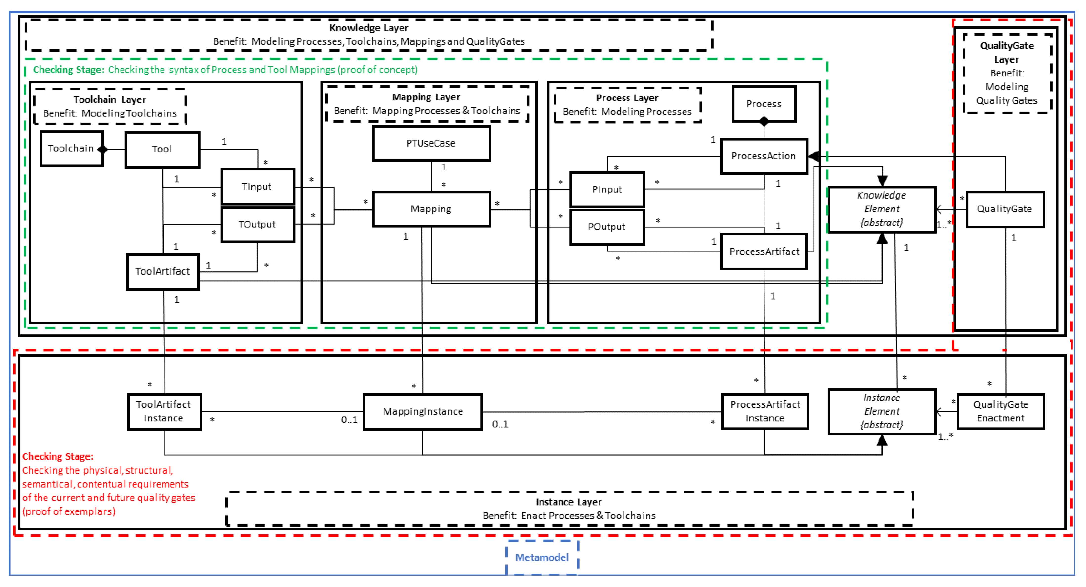
This subsection gives an overview of the proposed solution concept, which is represented in Figure 4. The whole approach is grounded in a metamodel (blue box) corresponding to the Lin2 level [42]. In its core, the metamodel facilitates modeling software development processes, modeling tools as part of a toolchain, use-case-based mappings between processes and tools to allow a seamless integration solution, and quality gates, including requirements. In addition, a two-part validation mechanism is established. The metamodel is divided into two general parts, the knowledge layer and the instance layer. This two-layer concept corresponds to the Accountability pattern of Fowler, where the instance layer complies with the operational one.
The knowledge layer consists of four sublayers: process, tool, mapping, and quality gate. The first two are involved in modeling processes and toolchains independently of each other, and they comply with the following principles.
ProcessArtifacts together with ProcessActions define a Process. Process modeling follows the UML Activity Diagram principles [45] (including, e.g., start-, split-, and conditional actions), and hence, the users can model object and control flows alike. The ProcessArtifacts can be connected with inputs (PInput) and outputs (POutput) from/to ProcessActions.
Similarly, a Toolchain contains Tools, ToolArtifacts, and the relations TInput and TOutput. The Toolchain modeling follows the UML Activity Diagram principles, too. The issues of the Toolchain modeling and the Process modeling are directed graphs.
The mapping layer consists of the classes Mapping and PTUseCase. The class Mapping allows the linkage of Tools and Processes so that the development process can be tracked and, thus, aid the different certification requirements. Mapping classes are part of PTUseCase, whose components link PInputs with TInputs and POutputs with TOutputs, i.e., ProcessActions are connected to Tools that realize them via their corresponding in- and outputedges.
Figure 5 shows an example of a PTUseCase and two Mappings between Processes and Toolchains on the linguistic levels Lin1/Lin2 and the ontological level Ont1 on the right side. The level appurtenance of the elements is illustrated with colors. The Process has a control and an object flow, two ProcessArtifacts, one ProcessAction, one PInput, and one POutput. The Toolchain has only an artifact flow, one Tool, three ToolArtifacts, two TInput, and one TOutput. The input- and outputedges are connected by one PTUseCase with two Mappings, the first PInput ep1 is linked to two TInputs, et1 and et2, by the first Mapping, and the second POutput ep2 to the TOutput et3 by the second Mapping. The figure shows an extracted example of a corresponding Lin1/Lin2 Ont0 view that will be dealt with later.
The class Mapping corresponds to the Accountability Type of Fowler [42], which defines one legal pairing of Party Types. The edges of the directed graphs (PInput, POutput, TInput, TOutput) correspond to the Party Types.
ProcessArtifacts, ToolArtifacts, and Mappings are generalized (linguistic instance-of relationship) to an abstract KnowledgeElement with the purpose of encapsulating functionality and reducing connections. The KnowledgeElement can be connected to one or more QualityGates by a reference. By design, a QualityGate is a predicate expressed in Object Constraint Language (OCL) from the Object Management Group to define product states and product attribute values at certain project stages. QualityGates represent critical steps in the evolution of artifacts, and, within this evolution, several product-specific expressions must be true for the project to continue.
The instantiation of the knowledge layer is the instance layer with the benefit of enacting the integration of Processes and Toolchains. In fact, it is an ontological instantiation of Atkinson and Kühne to define the domain, e.g., the ProcessArtifactInstance is an ontological instance of ProcessArtifact, a secondary role, which is called Object in the Lin2 level. ProcessArtifactInstance is on a lower ontological level than ProcessArtifact. Things work analogously for the other four classes in this layer.
ProcessArtifactInstance, ToolArtifactInstances, and MappingInstances are generalized (linguistic instance-of relationship) to an abstract InstanceElement, which encapsulates functionality and reduces connections. InstanceElement can have one or more connections to QualityGateEnactment by a reference. The QualityGateEnactment binds the free variables, which were introduced in the terms of the QualityGate.
The correct linking of ToolArtifactInstances and ProcessArtifactInstances is ensured through MappingInstances—corresponding to the Accountabilities of Fowler—with user support and the information about where the ToolArtifacts are physically located. Whenever a MappingInstance is created, the MappingInstance uses its type to check its validity. For improved clarity, the instances of the PInputs, TInputs, etc. (Party) are not shown in Figure 3.
The levels Lin1 and Lin0 are not shown in Figure 3 either. There are more linguistic instance-of relationships from Lin2 to Lin1 and from Lin1 to Lin0. During the modeling time, it cannot be determined how many exemplars must be planned in a concrete project. For this reason, linguistic instances of ProcessArtifactInstances are created during the project planning on level Lin1, e.g., if SW-Specification is a linguistic instantiation of ProcessArtifact, then PrivateCustomerManagement:SW-Specification is a linguistic instance of ProcessArtifactInstances and an ontological instance of SW-Specification (compare with Figure 4). The elements of Lin1 represent the elements of the real world on Lin0, e.g., concrete digital ToolArtifactInstances exemplars in different versions, and their dependencies are created and worked on by concrete tools during the project.
There are two stages of validation. The first one (green box in Figure 4) focuses on the toolchain, process, and mapping layer and is employed for checking the syntax of Process and Tool Mappings—a proof of concept is briefly described in the next section. After that, the validation of the physical, structural, semantic, and content requirements of the current and future QualityGates with a hybrid validation—a proof of exemplars—are shortly described as future work. This can be seen in the red box in Figure 4, where we focus on the instance and quality gate layers.

3.2. Checking the Syntax of the Process and Tool Mappings

After presenting the solution concept, in particular, how Processes and Toolchains can be connected with PTUseCases and Mappings, in this section, we describe how the proposed approach ensures that only valid mappings can be taken into consideration by checking their syntax. The requirements that we consider for such valid Mappings in this context are listed below.
Requirement 1: Type-conforming edgeMapping. A set of PInputs can be mapped only to a set of TInputs. A set of POutputs can be mapped only to a set of TOutputs. This requirement is covered by the implementation of the Accountability pattern.
Requirement 2: Assurance of the execution semantic. The UML Activity Diagram token semantic is based on Petri nets [46]. The firstMapping of a PTUseCase lays tokens on the edges of the Process and the Toolchain that the Mapping contains. The tokens wander to the first ProcessAction(s) and Tool(s). If all required tokens fit on the ProcessAction(s), this (these) will be executed and will, thus, trigger the related Tool(s) under the condition that all of the required tokens were present. After these executions, the tokens go out of the ProcessAction(s) and Tool(s) monitored by the PTUseCase until the second Mapping—if there is one—of the PTUseCase is achieved. Thus, it is important that no Mapping blights this execution semantic. This requirement cannot be covered by the Accountability pattern.
Requirement 3: An (almost) perfect coverage of theProcessesthroughToolchains. This is useful for certification needs and for analyzing time and cost reductions, e.g., which Tool is not/less used by Processes.
There are four mechanisms for supporting the validation stages and meeting the requirements, which are detailed in the following paragraphs: sequence checking, type filtering, cross-checking Mapping, and cross-checking PTUseCase. The first and the third mechanism are realizable with OCL.
Sequence checking. The mechanism of the sequence checking validates whether the process sequence requirements are fulfilled by the toolchains. ProcessActions contain an attribute called steptype, which defines whether the ProcessAction needs Tool support or not. A simple algorithm checks whether each edge (PInput, POutput) of the Tool-supported ProcessActions of a Process is connected in a Mapping of a PTUseCase with a TInput or, rather, a TOutput. There are three input parameters for this algorithm: every PInput, every POutput, and every Mapping of the investigated Process. The outcome is a string with the information of what percentage of the investigated Process is covered by the Toolchain and which ProcessActions are not yet covered. An extension is a check on which parts of the Toolchains do not yet belong to a Mapping. This mechanism fulfills Requirement 3.
Type filtering. The just-in-time type filtering ensures that POutput elements can only be mapped to other TOutput elements and PInput elements can only be mapped to other TInputs. This corresponds to the legal pairing of Party Types by Fowler. This mechanism fulfills Requirement 1.
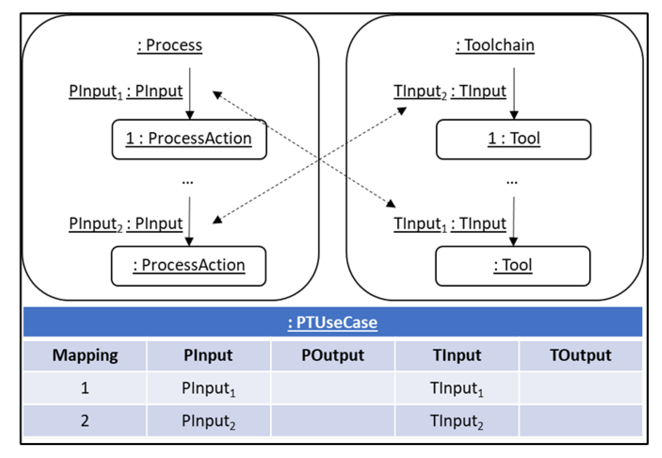
Cross-checkingMapping. The next two cross-checking mechanisms are more complicated, but they fulfill Requirement 2. The problem is shown in Figure 6 as an example. A Mapping may have a PInput1, which is located at the beginning of a Process. TInput1 is located at the end of a Toolchain and is connected in the Mapping with PInput1. A problem occurs if there is a second mapping connecting PInput2 (at the end of the mentioned Process) with TInput2 (at the beginning of the mentioned Toolchain). When this happens, a crossover—or, more precisely, a sequence problem—can be noticed because PInput1 comes before PInput2 and TInput1 comes before TInput2.
The first phase of the solution is a strict-order forming of the edges in directed Process and Toolchain graphs. If there is a directed way/path from an Edge1 to an Edge2, then Edge1 < Edge2. However, this is not trivial because of the existence of cycles in Toolchains or Processes. The solution is an algorithm for finding the elements of a Toolchain and a Process, which may be (at the same time) maximal in a PTUseCase.
Steps:
1.
Use the algorithm of Tarjan [47] separately for Toolchains and Processes to find the strongly connected components (SCCs) in order to identify the problematic cycles. An SCC is a part of a graph where every node is reachable from every other node of the part. Summarize every SCC with multiple elements to a new node, but store the edges within this SCC for later.
2.
Determine the strict orders in the modified Toolchains and Processes.
3.
Analyze the cycle types [48] for every multi-element SCC as follows.
  • Cycle type 1: The whole Toolchain/Process is just one SCC.
  • Cycle type 2: There exists exactly one inputedge in the SCC of the Toolchain/Process or, rather, more inputedges (from outside) in the same element of the SCC.
  • Cycle type 3: There exists more than one inputedge (from outside) in different elements of the SCC.
4. (a) 
Only for Toolchains; for SCCs with cycle types 1 and 2, the rules hold: “It is forbidden to put more than one edge of this SCC together in the same PTUseCase” and “It is forbidden to put an edge of this SCC together with an edge of another multi-element SCC in the same PTUseCase”. SCCs with cycle type 2 have a clear starting point. Start here and determine the strict orders within the SCC (with the stored edges of step 1) until there is a back-edge. Mark the back-edges. The determined strict-order edge elements are not affected by the rules.
   (b) 
Exception for Processes; this step is analogous to step 4a. However, in Processes, there is, additionally, a control flow. Coming from the starting point in the control flow, it is possible to identify a clear starting point in a multi-element SCC with cycle types 1 and 3 as well. Under this circumstance, the procedure for cycle types 1 and 3 is the same as that of cycle type 2.
5.
Consider the marked back-edges and determined the entirety of the strict orders in the Processes and Toolchains.
6
Consider the rules and form the orders of all valid PTUseCases—until now—with their maximum elements.
For the second phase of the solution, the PTUseCase and Mappings are analyzed from a mathematical point of view, and strict orders are used for mathematical mappings and restrictions. The first observation is that there is a morphism fMAP by using Mappings of PTUseCases, which maps PInputs or POutputs of a Process to TInputs or TOutputs of a Toolchain. This requires that the Mappings in PTUseCases are strictly isotone with the mapping f M A P s t r i c t , which is defined as follows.
Definition 1.
Cross-checking Mapping restriction. Let P , T directed Graphs for the Process and Toolchain and let ( E P , < e p ) , ( E T , < e t ) be two strict orders, one for Processes and one for Toolchains. For the Mappings of a PTUseCase exists a mapping f M A P s t r i c t with
( v , w ) E P f M A P s t r i c t ( v ) , f M A P s t r i c t ( w ) E T for all Elements v , w E P : v < e p w f M A P s t r i c t ( v ) < e t f M A P s t r i c t ( w )
Cross-checkingPTUseCase. To avoid crossovers between PTUseCases, the solution of the cross-checking Mapping can be reused. This requires a strict isotone mapping between PTUseCases, which is defined as follows.
Definition 2.
Cross-checking the PTUseCase restriction. Let ( E P , < e p ) and ( E T , < e t ) be two strict orders, one for Processes and one for Toolchains. Let a E P in PTUseCase1 and let a E P in PTUseCase2 Then, for all a,a’:
a < e p a f ( a ) < e t f ( a )
These four mechanisms (sequence checking, type filtering, cross-checking Mapping, and cross-checking PTUseCase) are essential for checking the syntax of Process and Toolchain Mappings.

4. Discussion

4.1. Evaluation

Schramm et al. [13] already explained the prototypical technical implementation of the concepts shown here and demonstrated their feasibility in the TOPWATER tool, and below, we briefly present their work for reasons of application and evaluation.
In order to allow a formal tool qualification [49], which means that a tool can be qualified according to a given standard and it can be mapped to an assessable process in order to create a certification-ready work environment, TOPWATER is integrated with the Validas toolchain. To permit an easy integration in various toolchains, TOPWATER’s metamodel is developed within the Eclipse Modeling Framework, which is known to allow the generation of a modeling tool starting with the metamodel.
A complete safety case and the ISO 26262:2018 chapters 6 and 8 were modeled in TOPWATER and assessed by TÜV Süd (Technischer Überwachungsverein; English: Technical Inspection Association—German businesses that provide independent inspection and product certification services). Due to the confidentiality of the cases and data involved, the TOPWATER paper presents an anonymized and simplified scenario case, which covers the tool qualification process, the mapping of standards’ requirements and their mapping to tools, the mapping of processes and tools, and the generation of compliance reports.
More concretely, the problem of checking whether a defined process has been performed or not is posed. TOPWATER allows the modeling of processes, artifacts, and tool models. This integrated modeling approach aims to reduce breaks in processes and toolchains, which are critical in safety-critical system development. Another feature of the tool consists in its ability to import process models. A process is thus connected with the tools used to enact it and the standard, which needs certain activities to be executed in order to be eligible for certification. TOPWATER provides a mapping on the basis of which an integrated model can be created and evaluated for consistency and compliance. Moreover, it supports the generation of the reports required by the certification authorities. It can be directly integrated with the project involved as well. The project’s progress can be tracked and, to a certain extent, predicted by continuously maintaining its state through constraint-based quality gates, thus making early plan deviations possible, in principle. Last but not least, the qualification method implemented by means of TOPWATER is able to validate itself as well.

4.2. Summary and Future Work

Because of the growing importance and complexity of software, development processes and toolchains are mandatory for supporting software engineering. The synergy effects in the key factors’ quality, time, and costs are more positive if processes and toolchains are completely integrated and the integration has validation mechanisms.
This article presented an approach whereby a unified metamodel is used to specify how Processes and Toolchains are linked by Mappings and so-called PTUseCases. The metamodel uses the Accountability pattern of Fowler and the linguistic and ontological metamodeling view of Atkinson and Kühne.
Furthermore, the concept ensures that only valid mappings can be produced by checking the syntax of such mappings. Three requirements for such valid mappings in this context were considered: type-conforming edge Mapping, assurance of the execution semantic, and an (almost) perfect coverage of the Processes through Toolchains. These requirements were covered by four mechanisms: sequence checking, type filtering, cross-checking Mapping, and cross-checking PTUseCase. For the cross-checking, the algorithm of Tarjan and strict orders have an important role.
The metamodel also allows a proof of exemplars to check the physical, structural, semantic, and content requirements of the current and future QualityGates, as shown by the red box in Figure 3. Because of the validation view of the present and the future, the employed validation method is a hybrid one, which allows support for quality assurance activities and the checking of a project’s progress.
This uses a validation model based on QualityGates, which is a predicate expressed in OCL to define product states (e.g., every SW-Specification is finished) and product attribute values (e.g., every SW-Specification has exactly one assignment to a SW-Architecture) at certain project stages. Hence, they have an assignment to one or more ProcessActions (e.g., Create SW-Specifications). QualityGates represent critical steps in the evolution of artifacts, and, within this evolution, several product-specific expressions must be true for the project to continue.
During the modeling time of the ProcessArtifacts, it is not possible to know how many instances are needed. For this, concrete ProcessArtifact Instances are created during the planning phase of a project on Lin1. During the project execution, real-world artifacts of ToolArtifacts Instances and their dependencies are created and modified by Tools on Lin0. They could fulfill the concepts, which are defined in their assigned ProcessArtifactInstances or ProcessArtifacts on Lin1, in whole or in part. These concepts (physical, structural, semantic, and content requirements) can be validated by QualityGates with the hybrid validation. Additionally, the information about the physical data storage path is defined in the ToolArtifacts.
The QualityGate validation provides two views, the closedworld view (CWV) and the open-world view (OWV). The CWV focuses on supporting completeness checks of real-world artifacts. To this end, an artifact-specific expression is assumed to be false (i.e., a quality criterion is not yet fulfilled) whenever it is not evaluated as true for a certainty. Thus, performing a validation on a QualityGate and all artifacts assigned to it provides an overview of all incomplete artifacts and, particularly, the attributes that cause the tests to fail. On the other hand, the OWV assumes an expression to be true, regardless of its actual evaluation. Consequently, this view provides a broader picture of the modeled project and supports prediction. This is achieved by checking which subsequent QualityGates might be fulfilled given the current project status. The prediction can be used to identify QualityGates that can be reached according to plans, as well as to identify those QualityGates that cannot be reached anymore, should the process be executed as planned and without modification. Such predictions can be used for early deviation detection, thus enabling project managers to initiate counteractions as early as possible.
The proposed concept reduces the current research gap, as it primarily integrates toolchains on the process integration level. The process integration level influences the control and data integration of the tools. The prototypical technical implementation TOPWATER [13] partially covers the presentation integration, but should not share a common look and feel in the concrete tools from the user’s perspective. The presented approach takes all abstraction levels into account. The first validation stage focuses on the toolchain, process, and mapping layer and has the ability to check the syntax. The hybrid validation checks the physical, structural, semantic, and content requirements of the current and future QualityGates.
The model-based approach improves consistency, requires less writing (mainly management), and has model guides throughout the process. Furthermore, an empirical analysis of the concept implemented in the TOPWATER tool can be investigated. The evaluation is limited to descriptive results. It could be enriched with insights into the validation mechanisms and threats and some initial statistical results. Furthermore, the hot-swap of toolchains due to cancellation, availability, or safety-criticalness, or the hot swap of processes due to new laws or compliance, could be another field for investigation. In addition, an article about the proof of exemplars in detail is currently under preparation.

Author Contributions

As part of his scientific work and still-pending doctoral thesis, J.S. contributed the contents of all chapters. A.R., U.A. (first and second doctoral supervisors), and H.F. accompanied him technically and in terms of the content of the work. All authors have read and agreed to the published version of the manuscript.

Funding

We acknowledge support from the Open-Access Publishing Fund of Clausthal University of Technology.

Institutional Review Board Statement

The study did not involve humans or animals.

Data Availability Statement

Not applicable.

Conflicts of Interest

The authors declare no conflict of interest.

References

  1. Klein, H. Collaborative Processes of Enterprises—Supporting Global Development; SSE-Dissertation 6; Verlag Dr. Hut GmbH: München, Germany, 2012; ISBN 9783843908238. [Google Scholar]
  2. Formento, H.; Chiodi, F.; Cusolito, F.; Altube, L.; Gatti, S. Key Factors for a Continuous Improvement Process. Indep. J. Manag. Prod. 2013, 4, 391–415. [Google Scholar] [CrossRef]
  3. Azeem Akbar, M.; Sang, J.; Nasrullah, D.; Khan, A.; Mahmood, S.; Furqan Qadri, S.; Hu, H.; Xiang, H. Success factors influencing requirements change management process inglobal software development. J. Comput. Lang. 2019, 51, 112–130. [Google Scholar] [CrossRef]
  4. Angermeier, D.; Bartelt, C.; Bauer, O.; Beneken, G.; Bergner, K.; Birowicz, U.; Bliß, T.; Breitenstrom, C.; Cordes, N.; Cruz, D.; et al. V-Modell-XT-Complete Version 1.3. 2018. Available online: http://ftp.tu-clausthal.de/pub/institute/informatik/v-modell-xt/Releases/1.3/V-Modell-XT-Complete.pdf (accessed on 8 February 2022).
  5. ISO 9000:2005. Available online: https://www.iso.org/obp/ui/#iso:std:iso:9000:ed-3:v1:en (accessed on 8 February 2022).
  6. Goldenson, D.; Gibson, D. Demonstrating the Impact and Benefits of CMMI®: An Update and Preliminary Results; SPECIAL REPORT CMU/SEI-2003-SR-009; Carnegie Mellon Software Engineering Institute: Pittsburgh, PA, USA, 2003. [Google Scholar]
  7. Ashrafi, N. The impact of software process improvement on quality: In theory and practice. Inf. Manag. 2003, 40, 677–690. [Google Scholar] [CrossRef]
  8. Niazi, M. Software Process Improvement: A Road to Success. In Proceedings of the International Conference on Product Focused Software Process Improvement PROFES 2006: Product-Focused Software Process Improvement, Amsterdam, The Netherlands, 12–14 June 2006; Volume 4034, pp. 395–401. [Google Scholar]
  9. CMMI Institute. Available online: https://cmmiinstitute.com/cmmi (accessed on 8 February 2022).
  10. Schramm, J.; Dohrmann, P.; Rausch, A.; Ternité, T. Process model engineering lifecycle: Holistic concept proposal and systematic literature review. In Proceedings of the 40th Euromicro Conference on Software Engineering and Advanced Applications (SEAA), Verona, Italy, 27–29 August 2014; pp. 127–130. [Google Scholar] [CrossRef]
  11. Padilla, E. Substation Automation Systems: Design and Implementation; John Wiley & Sons: New York, NY, USA, 2015; pp. 1–251. [Google Scholar] [CrossRef]
  12. Patanakul, P. An Empirical Study on the use of Project Management Tools and Techniques across Project Life-Cycle and their Impact on Project Success. J. Gen. Manag. 2010, 35, 41–65. [Google Scholar] [CrossRef] [Green Version]
  13. Schramm, J.; Rausch, A.; Fiebig, D.; Abu-Alqumsan, M.; Slotosch, O. Towards Alignment of Processes, Tools, and Products in Automotive Software Systems Development. In Proceedings of the The Tenth International Conference on Adaptive and Self-Adaptive Systems and Applications, Barcelona, Spain, 18–22 February 2018. [Google Scholar]
  14. Kuhrmann, M.; Kalus, G.; Then, M. The Process Enactment Tool Framework-Transformation of Software Process Models to Prepare Enactment. Sci. Comput. Program. 2014, 79, 172–188. [Google Scholar] [CrossRef]
  15. Kaiser, G.E.; Barghouti, N.S.; Sokolsky, M.H. Preliminary experience with process modeling in the MARVEL software development environment kernel. In Proceedings of the Twenty-Third Annual Hawaii International Conference on System Sciences, Kailua-Kona, HI, USA, 2–5 January 1990; Volume ii, pp. 131–140. [Google Scholar] [CrossRef]
  16. Krisnadhi, A.; Sengupta, K.; Hitzler, P. Local Closed World Semantics: Keep it simple, stupid! In Proceedings of the 24th International Workshop on Description Logics (DL 2011), Barcelona, Spain, 13–16 July 2011. [Google Scholar]
  17. Bergner, S.; Bartelt, C.; Bergner, K.; Rausch, A. Methodology for an Ontology-Driven Product Configuration Process; Universitätsverlag Ilmenau: Clausthal-Zellerfeld, Germany, 2016; pp. 1491–1502. [Google Scholar]
  18. Eclipse Process Framework. Available online: https://www.eclipse.org/epf/ (accessed on 8 February 2022).
  19. V-Modell XT Editor. Available online: http://fourever.sourceforge.net/ (accessed on 8 February 2022).
  20. AutoFocus3 Modeling Platform. Available online: https://www.fortiss.org/en/results/software/autofocus-3 (accessed on 8 February 2022).
  21. Portillo-Rodríguez, J.; Vizcaíno, A.; Piattini, M.; Beecham, S. Tools used in Global Software Engineering: A systematic mapping review. Inf. Softw. Technol. 2012, 54, 663–685. [Google Scholar] [CrossRef]
  22. Eclipse. Available online: https://www.eclipse.org (accessed on 8 February 2022).
  23. MS Team Foundation Server. Available online: http://www.visualstudio.com/en-us/products/tfs-overview-vs.aspx (accessed on 8 February 2022).
  24. IBM Rational Team Concert. Available online: https://www.ibm.com/docs/en/elm/6.0.1?topic=overview-rational-team-concert (accessed on 8 February 2022).
  25. Swordfish SOA Runtime Framework Project. Available online: cthttp://www.eclipse.org/swordfish/ (accessed on 8 February 2022).
  26. Agosense.symphony. Available online: https://agosense.com/en/products/agosensesymphony (accessed on 8 February 2022).
  27. ToolNet. Available online: https://www.es.tu-darmstadt.de/forschung (accessed on 8 February 2022).
  28. ModelBus. Available online: http://www.modelbus.org/en/modelbusoverview.html (accessed on 9 February 2022).
  29. SPRINT. Available online: http://www.sprint-iot.eu/ (accessed on 9 February 2022).
  30. Saadatmand, M.; Bucaioni, A. OSLC Tool Integration and Systems Engineering—The Relationship Between the Two Worlds. In Proceedings of the SEAA’14, 2014 40th EUROMICRO Conference on Software Engineering and Advanced Applications, Verona, Italy, 27–29 August 2014; IEEE Computer Society: Washington, DC, USA, 2014; pp. 93–101. [Google Scholar] [CrossRef]
  31. Validas Toolchain Analyzer. Available online: http://www.validas.de/en/services/tca/ (accessed on 9 February 2022).
  32. Wasserman, A. Tool integration in software engineering environments. In Proceedings of the International Workshop on Environments on Software Engineering Environments; Springer: Berlin/Heidelberg, Germany, 1990; pp. 137–149. [Google Scholar]
  33. Jenkins. Available online: https://jenkins.io/ (accessed on 9 February 2022).
  34. CruiseControl. Available online: http://cruisecontrol.sourceforge.net/ (accessed on 9 February 2022).
  35. Atlassian Toolchain. Available online: https://www.atlassian.com/ (accessed on 9 February 2022).
  36. Amalfitano, D.; De Simone, V.; Maietta, R.R.; Scala, S.; Fasolino, A.R. Using tool integration for improving traceability management testing processes: An automotive industrial experience. J. Softw. Evol. Process 2019, 31, e2171. [Google Scholar] [CrossRef]
  37. Available online: https://www.methodpark.com/ (accessed on 9 February 2022).
  38. Bizagi Suite. Available online: https://www.bizagi.com/de (accessed on 9 February 2022).
  39. ModelPlex. Available online: https://link.springer.com/article/10.1007/s10703-016-0241-z (accessed on 9 February 2022).
  40. Fowler, M. Analysis Patterns: Reusable Object Models; Addison-Wesley Professional: Boston, MA, USA, 1996; pp. 22–27. [Google Scholar]
  41. Accountability Pattern. Available online: https://www.martinfowler.com/apsupp/accountability.pdf (accessed on 9 February 2022).
  42. Atkinson, C.; Kühne, T. Model-driven development: A metamodeling foundation. Softw. IEEE 2003, 20, 36–41. [Google Scholar] [CrossRef] [Green Version]
  43. Atkinson, C.; Kühne, T. The Essence of Multilevel Metamodeling. In UML 2001—The Unified Modeling Language. Modeling Languages, Concepts, and Tools; Gogolla, M., Kobryn, C., Eds.; Springer: Berlin/Heidelberg, Germany, 2001; pp. 19–33. [Google Scholar]
  44. OMG Meta Object Facility. Available online: http://www.omg.org/spec/MOF (accessed on 9 February 2022).
  45. OMG Unified Modeling Language. Available online: https://www.omg.org/spec/UML/About-UML/ (accessed on 9 February 2022).
  46. Peterson, J.L. Petri Nets. ACM Comput. Surv. 1977, 9, 223–252. [Google Scholar] [CrossRef]
  47. Tarjan, R. Depth-First Search and Linear Graph Algorithms. SIAM J. Comput. 1972, 1, 146–160. [Google Scholar] [CrossRef]
  48. Schindler, B. Ensuring the Consistency of Requirements and Architectures (Konsistenzsicherung von Anforderungen und Architekturen); SSE-Dissertation 10; Verlag Dr. Hut GmbH: München, Germany, 2014; ISBN 9783843917032. [Google Scholar]
  49. Wildmoser, M.; Philipps, J.; Slotosch, O. Determining Potential Errors in Tool Chains: Strategies to Reach Tool Confidence According to ISO 26262. In Proceedings of the SAFECOMP’12, 31st International Conference on Computer Safety, Reliability, and Security, Magdeburg, Germany, 25–28 September 2012; Springer: Berlin/Heidelberg, Germany, 2012; pp. 317–327. [Google Scholar] [CrossRef]
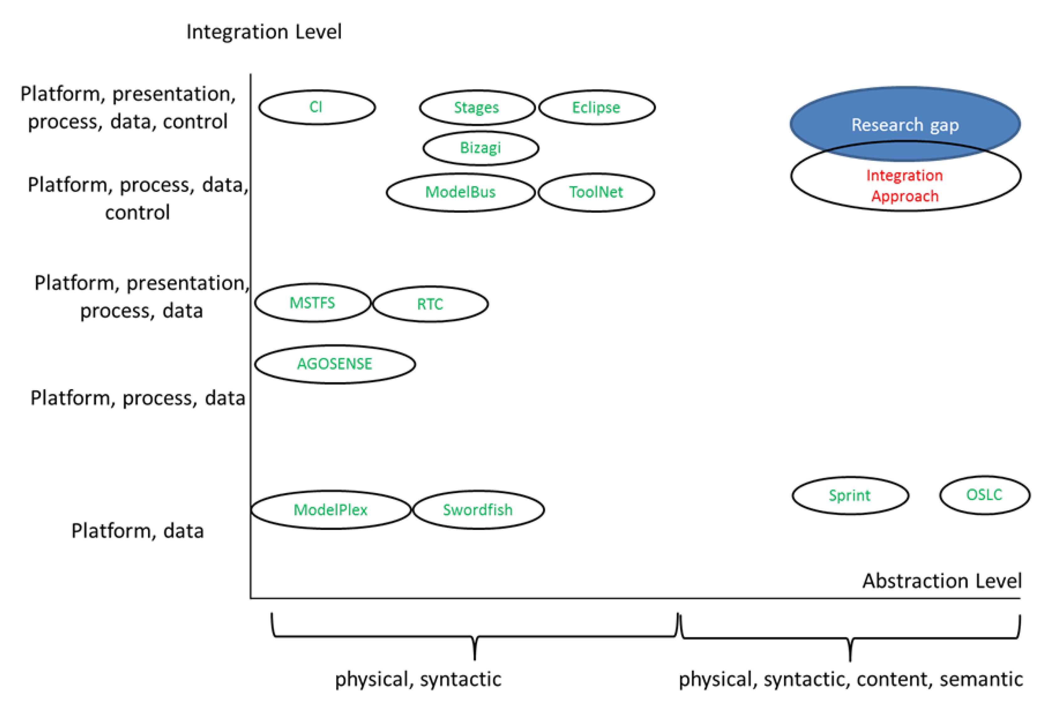
Figure 1. Identifying the research gap.
Systems 10 00040 g001
Figure 2. Accountability pattern with the knowledge level for directed graphs (customized) [41].
Systems 10 00040 g002
Figure 3. Linguistic and ontological metamodeling view (customized by adding the linguistic and ontological levels) [42].
Systems 10 00040 g003
Figure 4. Solution concept (overview).
Systems 10 00040 g004
Figure 5. Mapping processes and toolchains.
Systems 10 00040 g005
Figure 6. Mapping crossover problem.
Systems 10 00040 g006
Publisher’s Note: MDPI stays neutral with regard to jurisdictional claims in published maps and institutional affiliations.