Article

CFD-PBM Approach with Different Inlet Locations for the Gas-Liquid Flow in a Laboratory-Scale Bubble Column with Activated Sludge/Water

1
School of Civil Engineering, Southwest Jiaotong University, Chengdu 610031, China
2
School of Energy and Power Engineering, Xi’an Jiaotong University, Xi’an 710049, China
*
Author to whom correspondence should be addressed.
Computation 2017, 5(3), 38; https://doi.org/10.3390/computation5030038
Submission received: 14 July 2017 / Revised: 28 July 2017 / Accepted: 9 August 2017 / Published: 14 August 2017
(This article belongs to the Section Computational Engineering)

Abstract

:
A novel computational fluid dynamics-population balance model (CFD-PBM) for the simulation of gas mixing in activated sludge (i.e., an opaque non-Newtonian liquid) in a bubble column is developed and described to solve the problem of measuring the hydrodynamic behavior of opaque non-Newtonian liquid-gas two-phase flow. We study the effects of the inlet position and liquid-phase properties (water/activated sludge) on various characteristics, such as liquid flow field, gas hold-up, liquid dynamic viscosity, and volume-averaged bubble diameter. As the inlet position changed, two symmetric vortices gradually became a single main vortex in the flow field in the bubble column. In the simulations, when water was in the liquid phase, the global gas hold-up was higher than when activated sludge was in the liquid phase in the bubble column, and a flow field that was dynamic with time was observed in the bubble column. Additionally, when activated sludge was used as the liquid phase, no periodic velocity changes were found. When the inlet position was varied, the non-Newtonian liquid phase had different peak values and distributions of (dynamic) liquid viscosity in the bubble column, which were related to the gas hold-up. The high gas hold-up zone corresponded to the low dynamic viscosity zone. Finally, when activated sludge was in the liquid phase, the volume-averaged bubble diameter was much larger than when water was in the liquid phase.

1. Introduction

The bubble column, which is a reactor that is widely applied in chemical engineering and biochemical industrial processes, can be used in the activated sludge process to treat industrial sewage and municipal wastewater. Due to the complex nature of two-phase flow in bubble columns, researchers have studied two-phase hydrodynamic behavior experimentally [1,2,3] and using numerical simulations [4]. However, the fundamental properties of two-phase hydrodynamics, such as the liquid-gas two-phase flow with a non-Newtonian liquid, remain incompletely understood.
Because of its cost-effective nature and ability to conveniently predict behavior, such as liquid-phase velocities and gas hold-up values, at different positions in a bubble column, numerical simulation has been extensively applied. The models used for numerical simulations of the gas-liquid two-phase flow in bubble columns mainly include the Euler-Euler two-fluid model [5], Euler-Euler two-fluid model coupled with a population balance model (PBM) [6,7,8] and discrete particle model (DPM) [4]. The PBM accounts for the effects of bubble coalescence and breakup and can predict the local bubble size distribution [9]. The methods of solving the PBM include the discrete homogenous method [10], discrete inhomogeneous method [11], quadrature method of moments [12], and direct quadrature method of moments [13]. The Euler-Euler two-fluid model coupled with PBM has the potential for higher accuracy than the Euler-Euler two-fluid model and therefore can potentially predict the gas-liquid exchange area more accurately. Although simulations of multi-phase flow in the bubble column are based on the fundamental physics, the drag force coefficient model [8] and turbulence model [14,15,16] must be considered in the simulation to determine an appropriate numerical simulation model.
Many studies of the gas-liquid two-phase flow in bubble columns are based on the use of water, which is a Newtonian fluid, as the liquid phase. However, little research has focused on non-Newtonian fluids, such as activated sludge. Due to the opacity of activated sludge, researchers have been unable to use particle image velocimetry (PIV) or laser Doppler velocimetry (LDV) to study the velocity field, flow regime type and gas hold-up distribution in bubble columns. Instead, the experimental research on activated sludge (i.e., a non-Newtonian fluid) as the liquid phase focuses on its rheological behavior, hydrodynamics (mean shear rate) and volumetric oxygen transfer coefficient [17]; the velocity field, gas hold-up distribution, and bubble diameter in bubble columns have not been studied.
Currently, the commonly used liquid phases in simulation studies are other transparent non-Newtonian fluids, such as sodium carboxymethyl cellulose (CMC) aqueous solution [18,19]. The selected mathematical models include the Euler-Euler framework-based Euler-Euler two-fluid model and the Euler-Lagrange framework-based DPM model [20,21,22,23]. Most of the reported numerical simulations focus on single-bubble diameter and neglect the bubble coalescence and breakup effects in the non-Newtonian liquid phase because of the lack of research on the coalescence and breakup kernel function in the non-Newtonian liquid phase. Furthermore, the gas-liquid numerical simulation model used for a non-Newtonian liquid phase differs from that used for a Newtonian liquid phase. The mathematical model for the drag force coefficient and dynamic viscosity of a non-Newtonian liquid phase is very different from that of a Newtonian liquid phase [24,25,26]. Few numerical simulation studies have considered the rheological properties of activated sludge (i.e., a non-Newtonian fluid) in biochemical installations. Dapelo et al. [21] simulated the gas-liquid two-phase flow in an anaerobic digestion installation under the Euler-Lagrange framework and found that the model reproduces the experimental data robustly and accurately. By simulating the gas-liquid two-flow in an anaerobic aeration installation with a non-Newtonian liquid, Wu [23] showed that the gas-liquid mixing efficiency is decided by the mixing mechanism and pump transport period.
However, the existing numerical simulations of a non-Newtonian liquid phase (i.e., activated sludge) in bubble columns rarely considered the rheological properties of activated sludge, the bubble breakage or coalescence processing and the effects of different gas inlet positions. In this work, a Euler-Euler two-fluid model coupled with PBM was used for the first time to simulate the liquid-gas two-phase flow with an opaque non-Newtonian liquid. Comparing the results of simulations and experiments [3,21], we simulated the gas-liquid two-phase flow with different gas inlet positions and liquid-phase properties in a laboratory-scale bubble column and analyzed the hydrodynamic behavior of gas-liquid two-phase flow. We aim to develop an appropriate numerical simulation model and provide guidance for the optimized design and gas inlet position selection for opaque non-Newtonian liquid phase in bubble columns.

2. Mathematical Models

An Euler-Euler two-fluid model was used to simulate gas-liquid two-phase flow, and PBM was used to simulate the bubble coalescence and breakage processes. During the simulations, the gas-liquid interphase heat transfer was ignored, and the two phases were considered incompressible fluids. We assumed that the mixture of the activated sludge and water is a single-phase liquid [27].

2.1. Euler-Euler Two-Fluid Model

Mass conservation equation:
t ( α q ρ q ) + ( α q ρ q u q ) = 0
Momentum conservation equation:
t ( α q ρ q u q ) + ( α q ρ q u q u q ) = α q p + α q τ q + α q ρ q g + F
where α is the volume fraction; ρ is the density, kg/m3; p is the pressure, Pa; g is the acceleration due to gravity, 9.8 m/s2; q is the phase division, with g being the gas phase and l being the liquid phase; and τ q is the shear stress tensor computed as follows:
τ q = μ e f f , q ( u q + ( u q ) T 2 3 ( u q ) I )
where μ e f f , q is the effective viscosity. The effective viscosity of the liquid phase consists of three terms—molecular viscosity, turbulent viscosity and bubble-induced turbulence—as shown below:
μ e f f , l = μ l + μ T , l + μ B , l
We adopted the Sato and Sekoguchi model [28] that has been widely used in the bubble column numerical simulations to address bubble-induced turbulence [29,30,31]. The formulation of viscosity due to the induced turbulence can be expressed as:
μ B , l = ρ l C μ , B α g d | u g u l |
where C μ , B is a constant: 0.6. The magnitude of the drag force was more than 100 times greater than those of the other forces, such as the virtual mass force and turbulent dispersion force. Therefore, we neglected the turbulent dispersion forces, virtual mass force, and wall lubrication force during our numerical simulations and considered only the drag and lift force [15]. F is the interphase force, which is calculated as follows:
F = F D + F l
The drag force F D and the lift force F l are considered in this work. The lift force is given by:
F l = C l α g ρ l ( u g u l ) × u g
where Cl is the lift coefficient: 0.5 [3,32]. The drag force can be determined as follows:
F D = 3 4 α g α l ρ l C D d | u g u l | ( u g u l )
where d is the bubble diameter, m. The drag force coefficient model CD considering the effects of the rheological properties of non-Newtonian fluids can be expressed as follows [24]:
C D = { 16 Re t ( 1 + 0.173 Re t 0.657 ) + 0.413 1 + 16300 Re t 1.09 Re t < 135 0.95 Re t > 135
Since Newtonian and non-Newtonian fluids exhibit different flow behaviors, the definition of the Reynolds number for Newtonian fluids is invalid for non-Newtonian fluids [33]. Therefore, the Reynolds number of spherical bubbles for non-Newtonian fluids Re t is calculated as follows [34]:
Re t = ρ l d n u t 2 n K
where K is the consistency coefficient, kg/(m·sn); n is the is the power-law index. The drag force coefficient model of the Newtonian fluid is calculated based on the literature [35].

2.2. Turbulence Modeling

Turbulent effects are modeled by the standard k ε model. This turbulence model is typically applied to predict the liquid flow pattern and gas hold-up under a low superficial gas velocity due to its simple algorithm and relatively low computational cost [5,36,37]. The standard k ε model can be expressed as follows:
( α q ρ q k q ) t + ( α q ρ q u q k q ) = ( α q μ e f f , q σ k k q ) + α q G k , q α q ρ q ε q
( α q ρ q ε q ) t + ( α q ρ q u q ε q ) = ( α q μ e f f , q σ ε ε q ) + α q ε q k q ( C 1 G k , q C 2 ρ q ε q )
where k is the turbulent kinetics energy; ε is the turbulent kinetics energy dissipation rate; C1 and C2 are constant.

2.3. Non-Newtonian Fluid Rheological Model

The liquid dynamic viscosity is constant (0.001003 kg/(m·s)) for water, which is a Newtonian fluid. The existing models describing the rheology of a non-Newtonian fluid such as activated sludge include the Ostwald de Vaele model, Herschel-Bulkley model, and Bingham model. In particular, Hasar et al. [25] found that the low-shear-speed Ostwald de Vaele model was suitable for practical purposes in studying the flow characteristics of activated sludge. The fitted results obtained by Mohapatra et al. [26] indicate that the Ostwald de Vaele model for wastewater sludge has a higher confidence level than the Bingham or Casson models. The equation for the molecular viscosity can be expressed as:
μ l = K γ ˙ n 1
where γ ˙ is the shear rate, s−1. It should be noted that the effects of temperature on the rheological properties of the sludge were ignored. In this article, the data from Durán et al. [16] were used to characterize the high-concentration activated sludge, where the activated sludge concentration was 7.9 g/L, K was 0.0741 kg/(m·sn) and n was 0.49.

2.4. Population Balance Model

To consider the bubble breakup and coalescence phenomena in bubble columns, a PBM can be applied to calculate the bubble size distribution as follows:
n ( v , t ) t + ( u n ( v , t ) ) = B a D a + B b D b
B a = 1 2 0 v n ( v v , t ) n ( v , t ) a ( v v , v ) d v
D a = 0 n ( v , t ) n ( v , t ) a ( v , v ) d v
B b = v β ( v , v ) g ( v ) n ( v , t ) d v
D b = g ( v ) n ( v , t )
where n(v, t) is the bubble size distribution function; Ba, Da, Bb and Db are the births due to coalescence, death due to aggregation, birth due to breakage, and death due to breakage, respectively. Equation (14) is solved using the discrete method solution [38]. The terms for the breakup phenomena are estimated using the Luo and Svendsen model [39]. The model described by Luo is used to model the coalescence processes [40]. The bubble diameter is discretized into 10 sub-classes ranging from 1.45 mm to 9.55 mm [3].
For a non-Newtonian liquid phase, we used the same breakage and coalescence kernel function, primarily based on the following reasons: (1) in the Navier-Stokes equation, we considered the non-Newtonian liquid rheological properties that are a partial influence on the coalescence and breakage processing. (2) It is very difficult to accurately measure the bubble diameter and establish the breakage and coalescence kernel model because of the opacity of activated sludge. (3) We further verified this assumption in Section 4.3.

3. Model Setup and Calculation Algorithm

3.1. Model and Mesh

3.1.1. Physical Model

We adopted the physical three-dimensional (3D) model described by Díaz et al. [3] as shown in Figure 1a, with model height = 0.45 m, length = 0.2 m, and width = 0.04 m. As shown in Figure 1b, the gas inlet is modeled as a rectangular area with dimensions of 0.018 × 0.006 m at the bottom of the central domain, which represents the experimental sparger setup. As shown in Table 1 and Figure 1c, we modeled eight different cases that varied according to the distance from the gas inlet center to the bottom center of the bubble column and the liquid properties.

3.1.2. Mesh

To obtain adequate simulation results compared with experimental data (Section 4.1), different numerical simulations were conducted using four meshes of structured cells (i.e., 1872, 3360, 10,395 and 22,185) to determine an ideal mesh, and a total of 10,395 cells was chosen for computational modeling (Section 4.1). As shown in Figure 2, the meshes in the x-, y- and z-directions were 21, 45 and 11, respectively.

3.2. Calculation Methods

The equations in Section 2 were discretized via the finite volume method, and the volume fractions were differentiated using the QUICK scheme. The time term was treated by a first-order scheme, whereas other terms were treated via a second-order upwind discretization scheme. The pressure and speed were coupled via the semi-implicit method for pressure-linked equation (SIMPLE). The inlet was set as a single-gas phase. The speed inlet boundary conditions were used: the superficial gas velocity was 0.0024 m/s, the outlet was set as a degassing boundary condition [30,41], and the other physical boundaries were set as solid-wall boundary conditions. The residual error was 10−5, the time step was 0.01 s, and the maximum iteration number was 30. Prior to obtaining the unsteady state numerical simulation results, we set the simulation result obtained from 1000 steady-state steps as the initial field of the unsteady state computation. The initial diameter is 5.95 mm. Numerical simulations were performed using the computational fluid dynamics (CFD) commercial code ANSYS Fluent 14.5.

4. Validation

4.1. Mesh Validation

As for the physical model of case 1 (Table 1) under four different grid dimensions, we simulated the aeration of pure water (i.e., a Newtonian fluid) and obtained simulation data for the average gas hold-up in the bubble column. The maximum iteration number and time step length at each step are given in Table 2.
Table 2 shows that increasing the grid density did not improve the comparability of the simulation results and the experimental data. This finding is in agreement with those reported by Díaz et al. [3] and Buwa et al. [42] and is attributable to the turbulent spectrum. The time step size and maximum iterative step influenced the simulation result but only very slightly. Thus, for the simulations, we selected the grid quantity at which the gas hold-up value was similar to the experimental result: 10,395. Further validation of the gas hold-up distribution was conducted as described in Section 4.2.

4.2. Flow Visualization: Experimental versus Simulated Results

The simulations of the gas hold-up distribution with the above physical model and mathematical method are shown in Figure 3, where the total number of mesh elements is 10,395. The bubble plume oscillates periodically over time. We picked out the most consistent result to the experimental result from the different instantaneous gas hold-up distribution simulation results. Comparing the simulation results with experimental observations reveals that the instantaneous simulated gas hold-up distribution (i.e., the plume) is S-shaped and that the maximum gas hold-up occurs near the inlet area. The simulated gas plume gradually widens from the bottom to the top, and all the simulated phenomena relating to the gas hold-up distribution were basically consistent with the experimental observations.

4.3. Non-Newtonian Velocity Field Verification

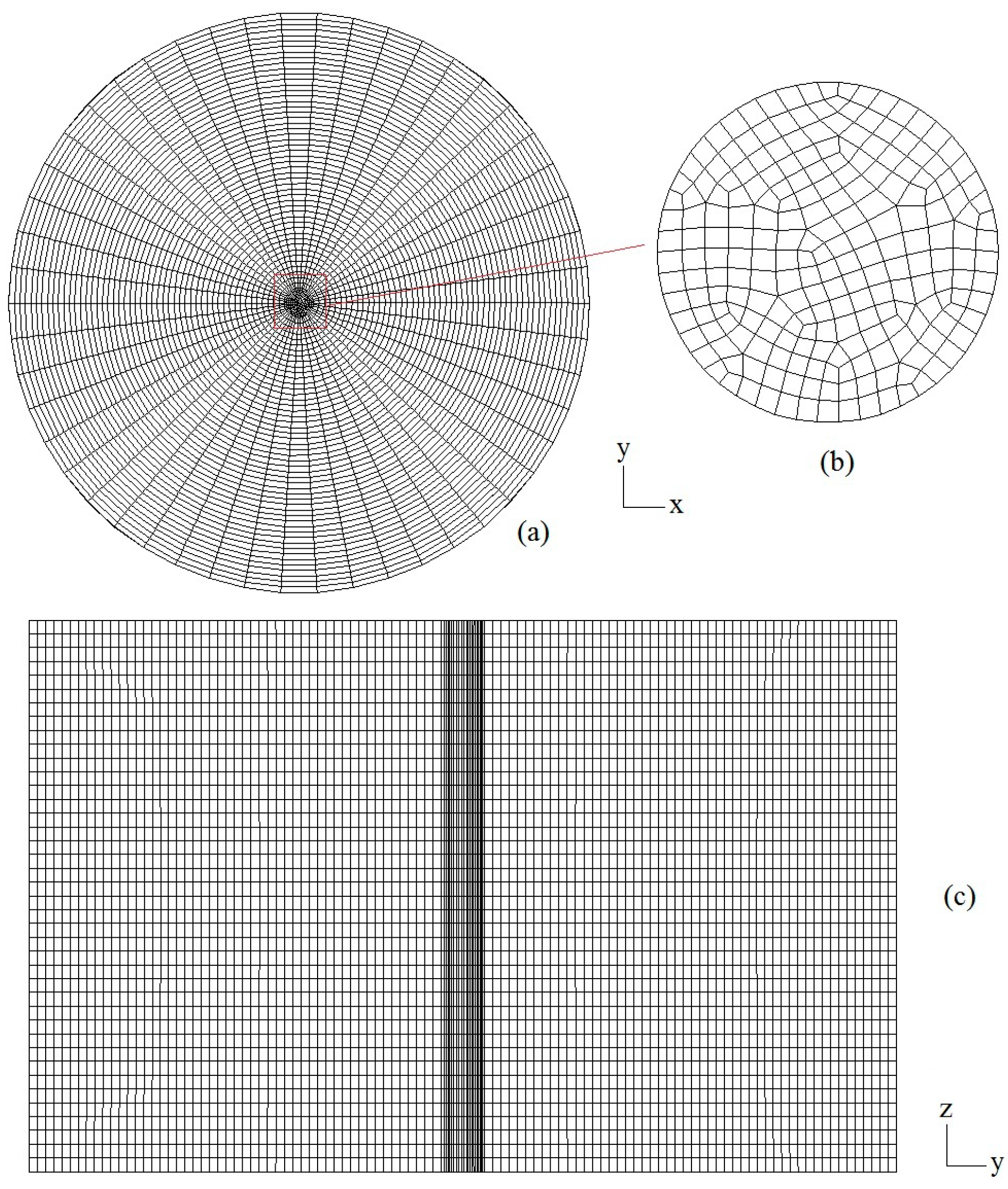
We performed numerical simulations of gas-liquid mixing during the anaerobic digestion in a non-Newtonian liquid phase (i.e., CMC solution) and compared our results with the experimental results reported by Dapelo et al. [21]. The CMC solution had a consistency coefficient of 0.209 kg/(m·sn) and a power-law index of 0.730. The equations, numerical methods, boundary conditions and bubble particle size distribution used for the numerical simulations were described in Section 2 and Section 3. The inlet velocity was 2.05 mL/s. The mesh division method is shown in Figure 4. Figure 4a presents the bottom mesh division, Figure 4b presents the inlet mesh, and Figure 4c presents the axial cross-sectional mesh division when the total number of mesh elements was 108,720.
Figure 5 presents the comparison of the simulation results for the time-averaged liquid-phase velocity magnitude distributions at different r/R ratios with the simulation results of Dapelo et al. [21] and the experimental results [21]. In the simulation described in this paper, the measured bubble diameter was 5.65 mm, lower than the experimental result (7.94 mm). The bubble diameter relative error between the experimental and simulation data is 28%, possibly because the bubble was assumed to be spherical and to undergo binary collision and breakup processes in the numerical simulations. Furthermore, comparing the velocity magnitudes at different r/R ratios revealed that the simulation results in this paper were better than those of Dapelo et al. [21] and that the numerical simulation method described here could reproduce the velocity magnitude, indicating that the assumptions of the non-Newtonian drag force, lift force, Newtonian coalescence and breakage kernel used for the low-velocity non-Newtonian liquid phase were rational.

5. Results and Discussion

5.1. Flow Field

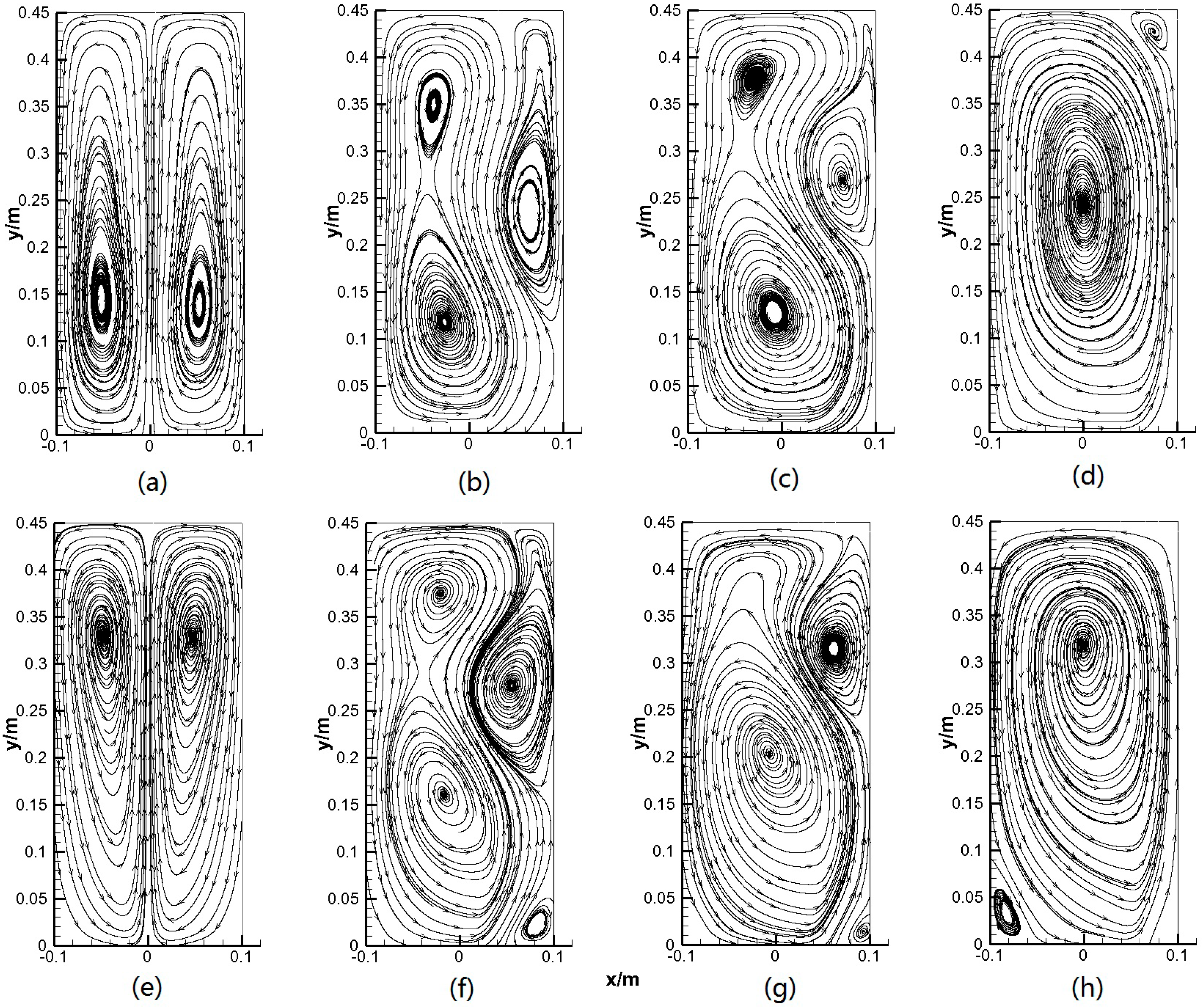
Figure 6 shows the time-averaged liquid-phase streamline at the cross section (z = 0 m) in the rectangular bubble column. The position of the inlet determines the form of the liquid-phase flow field. When the inlet was located in the middle of the bottom of the bubble column, two symmetric vortices were formed in the bubble column, and their centers were located in the lower part of the bubble column, as shown in Figure 6a. By contrast, when the inlet was shifted from the middle of the bottom of the bubble column, one main vortex was formed in the middle-left of the bubble column, and two small eddies were formed above the left and right sides of the bubble column, as shown in Figure 6b,c.
When the inlet was the farthest from the middle of the bottom of the bubble column, one large vortex encompassing the bubble column and one eddy were formed above the right side of the bubble column because the liquid phase was influenced by the boundary conditions at the top and the wall, as shown in Figure 6d. The flow field structure changed as the position of the inlet changed.
For the same inlet position, the liquid rheological properties also influenced the flow field in the bubble column. Comparing Figure 6a and Figure 6e shows that symmetric vortices were formed in the bubble column, but their centers were in different positions because of the different liquid-phase velocities in the bubble column (see Section 5.2). These differences also led to the difference between Figure 6d and Figure 6h. In addition, comparing Figure 6b and Figure 6c, and Figure 6f and Figure 6g reveals that when activated sludge was in the liquid phase, the influence area of the main vortex changed, and more small eddies were formed in the bubble column.

5.2. Velocity

5.2.1. Liquid-Phase Velocity in the y-Direction

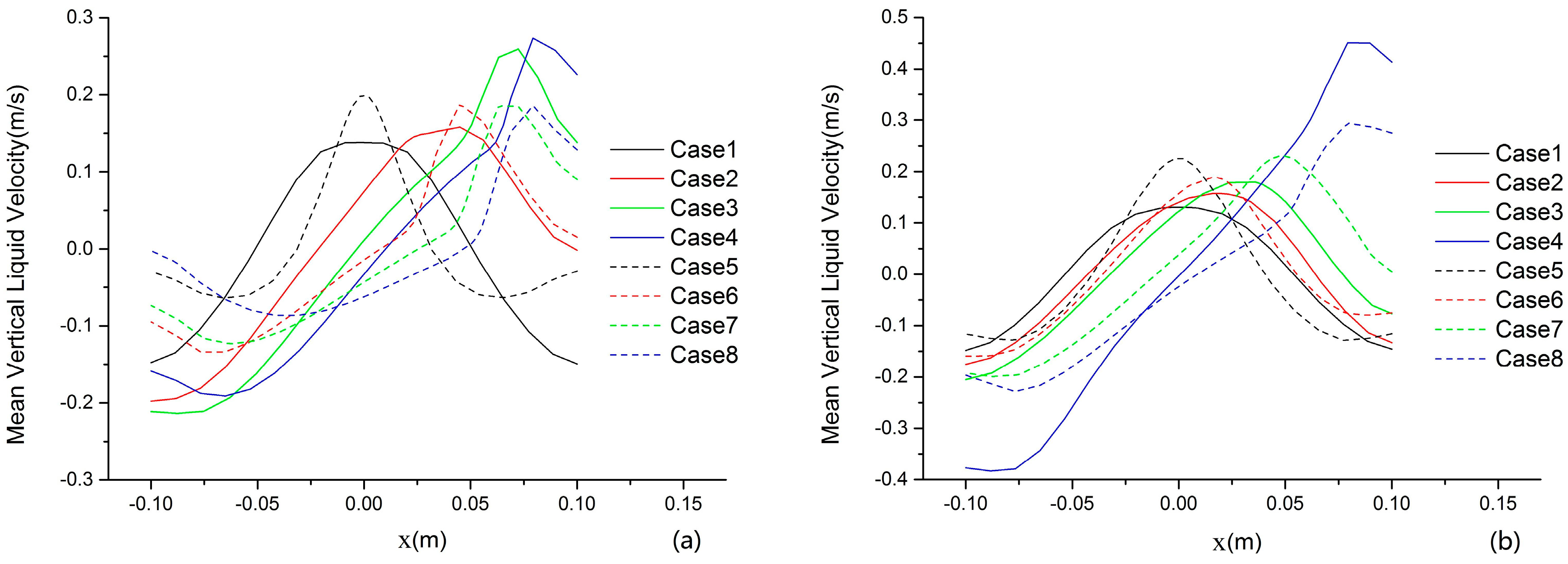
The velocities of a liquid phase in the y-direction at heights 0.09 m and 0.22 m at z = 0 m (i.e., at the bubble column centerline) in the bubble column were compared, as shown in Figure 7. As the inlet gradually shifted to the right from the middle of the bottom of the bubble column, the liquid-phase velocity peak value in the y-direction increased. Examination of Figure 7a,b shows that the velocity was much higher at 0.22 m than at 0.09 m from the bottom; at this point, the liquid phase was in the acceleration phase. Moreover, Figure 7a,b indicate that the maximum liquid-phase velocity occurred above the inlet of the bubble column, whereas the minimum velocity occurred at the two sides, indicating that the liquid was driven by the gas phase to flow up through the column to the top and then down to the column bottom along the column wall.
The two liquid phases (water and non-Newtonian sludge) showed different liquid velocity distributions in the y-direction. This difference was one of the reasons for the difference between the liquid-phase streamlines in the bubble column. In Figure 7a, as the inlet gradually shifted from the middle of the bubble column, the difference in the maximum velocity in the y-direction between water and activated sludge decreased gradually until a negative value was reached. In calculation cases 1 and 5 and calculation cases 2 and 6, the activated sludge exhibited larger liquid-phase maximum velocities in the y-direction than water. In contrast, when the inlet was close to the right wall (i.e., in calculation cases 4 and 8 and calculation cases 3 and 7), the maximum velocity in the y-direction of activated sludge was smaller than that of water, possibly because the viscosity was higher in the middle and upper parts of the right side in the column (see Section 5.4); this velocity change also influenced the gas hold-up. Figure 7b shows the liquid-phase velocity in the y-direction showed similar behavior.

5.2.2. Liquid-Phase Velocities at Different Monitoring Points

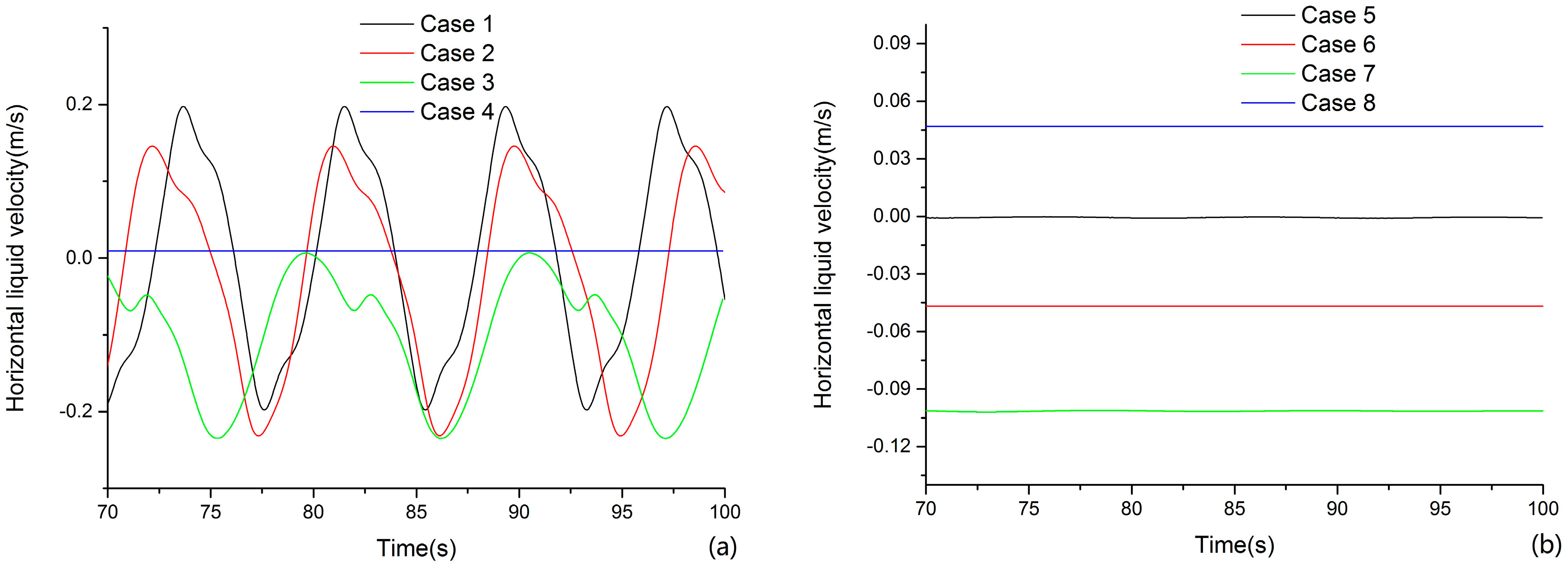
Figure 8 shows the instantaneous horizontal velocities of the liquid phase at the monitoring points: 0 m, 0.225 m, and 0 m. When the liquid phase was water, the oscillation period of the velocity in the x-direction increased as the inlet was shifted farther from the middle of the bottom of the bubble column, as shown in Figure 8a. When the inlet was the farthest from the middle of the bottom of the column (case 4), the liquid-phase velocity in the x-direction did not change over time, indicating that the plume did not periodically oscillate over time, mainly because the gas phase drove the liquid phase to form one quasi-steady-state vortex in the bubble column when the inlet was very close to the wall. Figure 6d shows the form of this vortex; the monitoring points were also near the vortex center. This arrangement is consistent with the lower velocity in the x-direction tending toward zero, as shown in Figure 8a, and with the stable vortex in the bubble column found in the simulation and experimental studies of the corner inlet [4].
The velocity of activated sludge as the liquid phase in the x-direction was constant, while the velocity of water as the liquid phase in the x-direction periodically oscillated, as shown in Figure 8b, because quasi-steady-state vortices were formed, and the velocities in the x-direction at the monitoring points did not change over time in the bubble column. Böhm et al. [43] experimentally studied the bubble upflow in a non-Newtonian liquid (xanthan solution), and their results showed that when the inlet was located in the middle of the bottom of the bubble column, the bubbles did not oscillate from side to side. Passos et al. [20] also found no periodical oscillations of the plume at low velocity during their experimental study of gas-liquid two-phase flow in the xanthan solution as the non-Newtonian liquid in the bubble column. The above studies show that the simulation results and experimental observations in this paper are consistent. In summary, the change in the velocity in the x-direction at the monitoring points was related to the inlet position and liquid rheological properties. The flow field velocity in the bubble column was constant due to the higher overall viscosity of the non-Newtonian liquid phase. For further analysis, we refer the reader to Section 5.4.

5.3. Gas Hold-Up

5.3.1. Gas Hold-Up Distribution

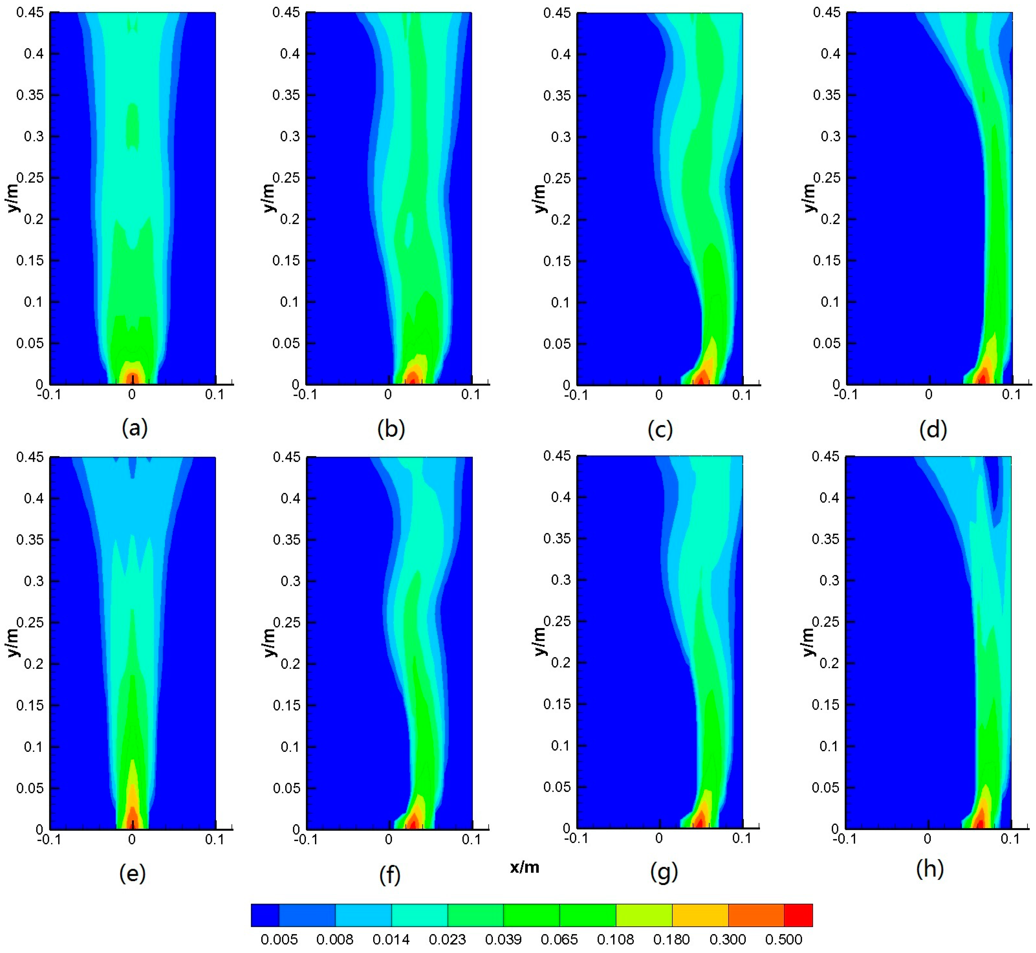
Figure 9 shows the time-averaged gas hold-up distribution at z = 0 m in the bubble column. The calculation cases for the different inlet positions indicated a smaller gas hold-up distribution area at the bottom and a larger gas hold-up distribution area at the top. When the inlet position was farther from the middle of the bottom of the bubble column, the gas-phase distribution area at the bottom gradually decreased, and one extremely low gas hold-up zone was found on the bottom and the walls at the two sides of the bubble column. For different liquid phases and inlet positions, the gas hold-up distribution in the bubble column varied. The gas hold-up distribution was symmetric at x = 0.1 m because the inlet position and physical model were symmetric at x = 0.1 m, as shown in Figure 9a. By contrast, the gas hold-up distribution was S-shaped in Figure 9b,c; the high-gas hold-up zone was close to the right wall of the bubble column and was cylindrical in the middle of the lower part of bubble column, as shown in Figure 9d.
Varying the liquid-phase properties affected the gas hold-up distribution. When activated sludge was in the liquid phase, the gas hold-up distribution was symmetric and exhibited a V shape, with very low gas hold-up values in the axial area in the middle and upper part of the bubble column, as shown in Figure 9e. In contrast, in Figure 9f,g, the gas hold-up distribution was S-shaped, but the gas hold-up distribution zones were very narrow in the middle and lower part of the bubble column. A low gas hold-up zone was found on the top of the right side of the bubble column, as shown in Figure 9h, possibly because of the high-dynamic viscosity at this location. This finding will be discussed in Section 5.4.

5.3.2. Global Gas Hold-Up

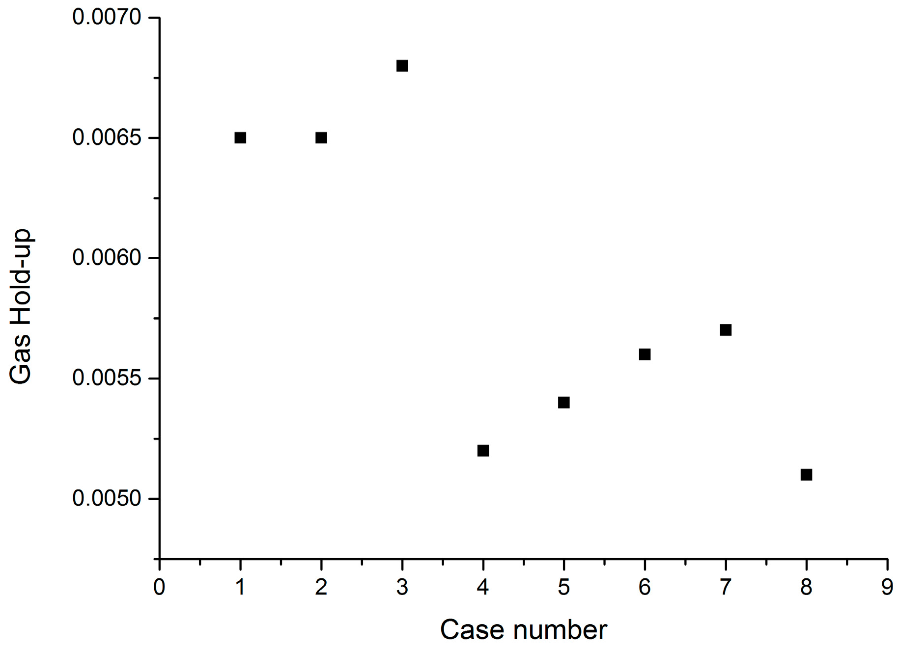
The global gas hold-ups in the bubble column for the different cases were compared, as shown in Figure 10. When water was in the liquid phase, calculation cases 1, 2, and 3 showed similar gas hold-ups. Case 4 had the smallest gas hold-up because the high gas velocity in the bubble column led to a shorter residence time of the gas in the liquid phase. The liquid was driven by the gas to flow through the bubble column, and thus, the liquid velocity indirectly reflected the gas velocity shown in Figure 7b. In contrast, when activated sludge was in the liquid phase, the gas hold-up was much lower than that of water in the bubble column. This finding was consistent with the results of Durán et al. [17], Mineta et al. [44] and Fransolet et al. [45] because an increase in the gas-phase upflow velocity led to a shorter residence time of the gas in the bubble column. Furthermore, in calculation case 4, water and activated sludge exhibited similar gas hold-up values in the bubble column because the higher dynamic viscosity of the non-Newtonian liquid at the top of the bubble column led to a large gas hold-up distribution zone.

5.4. Non-Newtonian Liquid Dynamic Viscosity

The higher dynamic viscosity of the non-Newtonian liquid led to lower flowability. Thus, the flowability was studied further by comparing the dynamic viscosity of the non-Newtonian liquid in the bubble column at different inlets, which helped elucidate the origins of the velocity and gas hold-up distribution. Figure 11 presents the dynamic viscosity distribution of the non-Newtonian liquid at z = 0 m in the bubble column. The maximum dynamic viscosity peak value of the non-Newtonian liquid occurred when the inlet was located in the middle of the bottom of the bubble column. The low-dynamic viscosity zone distribution was V-shaped and symmetrical at x = 0 m, and the peak values were found at the two sides at the bottom of the bubble column, indicating that in this zone, the flowability of the non-Newtonian liquid is lower. When the inlet was located between the middle and the right wall of the bubble column, the dynamic viscosity distribution and peak value were found on the bottom of the left side of the bubble column, while low-dynamic viscosity was observed on the right of the bubble column, as shown in Figure 11b,c. When the inlet was the farthest from the middle of the bottom of the bubble column, the non-Newtonian liquid its minimum dynamic viscosity peak value and much lower dynamic viscosity and high flowability at the zone close to the right wall from the bottom to the middle; however, a visible high-dynamic viscosity zone in the middle and upper part of the right side blocked the non-Newtonian liquid flow, as shown in Figure 11d. Lower gas hold-up was also found in this zone, as shown in Figure 9h. This phenomenon may explain why water (i.e., the Newtonian liquid phase) had a much higher velocity in the y-direction in the right side of the bubble column than the activated sludge (i.e., a non-Newtonian liquid).
Comparing the gas hold-up distributions and dynamic viscosity distributions of the non-Newtonian liquid revealed that these distributions are interrelated. Figure 9e shows the V-shaped hold-up distribution, and Figure 11a presents the V-shaped low-dynamic viscosity zone distribution. Figure 9f and Figure 11b, Figure 9g and Figure 11c, Figure 9h and Figure 11d revealed that high-gas hold-up zones always correspond to low-dynamic viscosity zones. This finding indicated that the liquid phase had strong flowability in the low-dynamic viscosity zone and that the gas phase always flowed up in this zone. Moreover, the instantaneous velocity did not change periodically, as shown in Figure 8b, possibly because of the influence of the dynamic viscosity of the liquid. The viscosity was small in the low-dynamic viscosity zones, and thus, the gas phase flowed up along these zones to form a gas upflow path in the bubble column.

5.5. Volume-Average Bubble Diameter

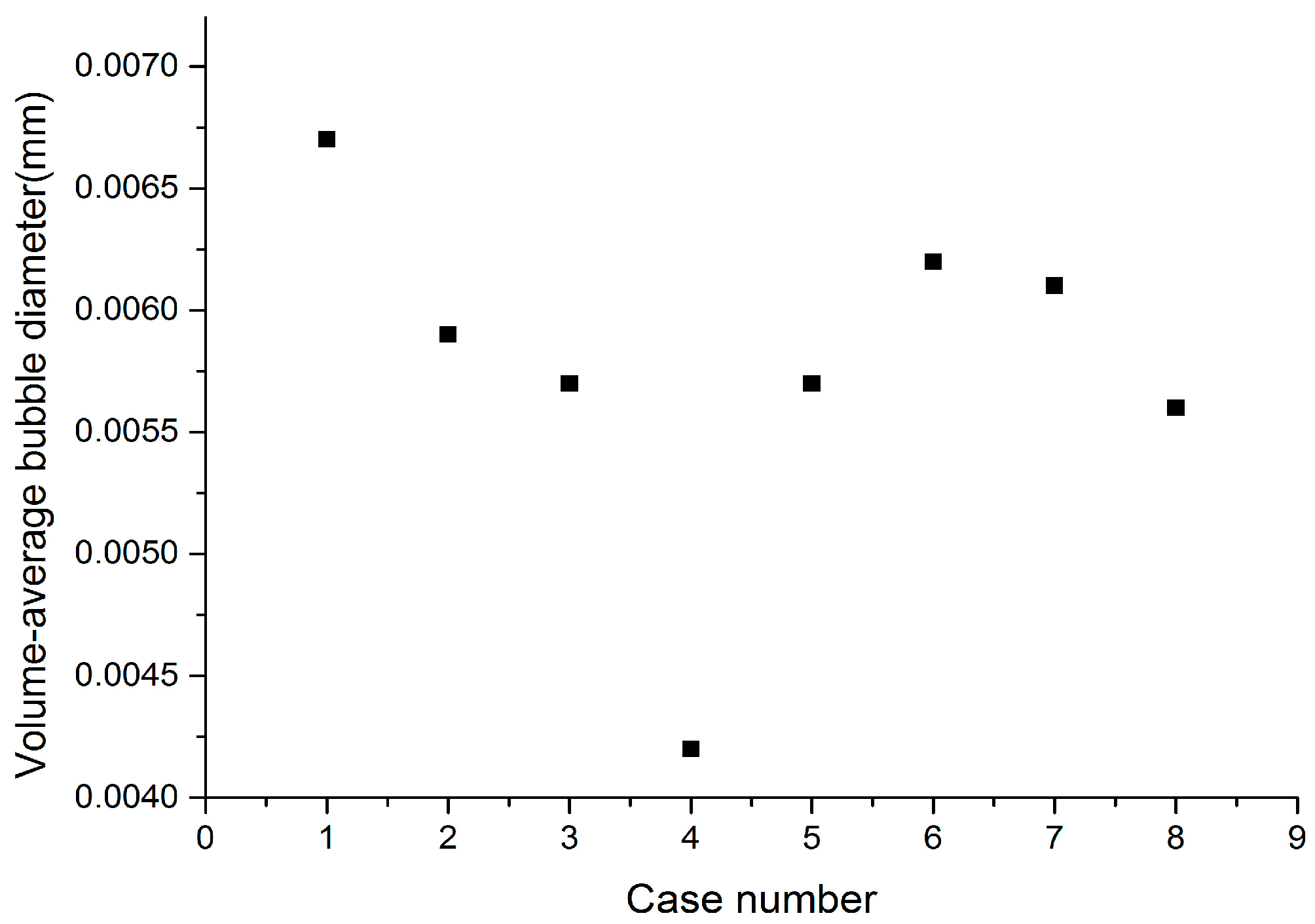
As an important bubble column parameter, the bubble diameter is highly meaningful for the prediction of the gas-liquid mass transfer in the bubble column. As shown in Figure 12, when water was the Newtonian liquid phase, the volume-averaged bubble diameter was small: 0.0057 m and 0.0042 m in cases 3 and 4, respectively, when the inlet was far from the middle of the bottom of bubble column. Larger values—0.0067 m and 0.0059 m—were found in cases 1 and 2, respectively, when the inlet was close to the middle of the bottom of bubble column. As shown in Figure 12, when activated sludge was the non-Newtonian liquid phase, the volume-averaged bubble diameter in the bubble column was similar to the values reported above, with case 6 showing the highest bubble diameter: 0.0062 m.
Moreover, we found that the activated sludge as the liquid phase exhibited slightly higher volume-averaged bubble diameters than water as the liquid phase, except in cases 1 and 5; these findings were in accordance with the experimental observations of Fabiyi and Novak [46].

6. Conclusions

We aimed to measure the gas mixing in the hydrodynamic behavior of activated sludge (i.e., an opaque non-Newtonian liquid), which has been difficult to measure experimentally in previous research. An Euler-Euler two-fluid model coupled with the PBM model was developed for numerical simulations of different liquid phases and inlet positions in the bubble column in this work. The following conclusions were obtained:
The inlet position and liquid rheological properties influenced the number of vortices, vortex distribution and vortex center in the flow field in the bubble column. Using water as the liquid phase provided some velocity fields in the bubble column that differed from those obtained using activated sludge as the liquid phase; i.e., as the inlet gradually shifted from the center of the bubble column, the difference in the maximum velocity in the y-direction between activated sludge and water decreased until a negative value was reached in the bubble column.
The inlet position influenced the gas hold-up. When water was in the liquid phase, the inlet position deviated farther from the bubble column, resulting in a larger gas hold-up; the lowest gas hold-up was observed when the inlet position was the farthest from the center of the bubble column. In contrast, when activated sludge was in the liquid phase, the gas hold-up was much lower than that of water, and as the inlet position moved farther from the center of the bubble column, the gas hold-up in the bubble column decreased.
When activated sludge was in the liquid phase, the liquid dynamic viscosity distribution influenced the gas hold-up distribution, and high-gas hold-up zones always corresponded to low-dynamic viscosity zones. The volume-averaged bubble diameter varied nonlinearly with the inlet position in the bubble column; i.e., as the inlet position moved farther from the center of the bubble column, the volume-averaged bubble diameter decreased. In contrast, when pure water was in the liquid phase, the volume-averaged bubble diameters were lower than when activated sludge was used in the simulations.
The study in this paper was based on the assumption that bubbles coalescence and breakup effect of in the non-Newtonian liquid phase was consistent with that in Newtonian liquid phase. This assumption is still defective. The future study focuses on (1) experimental study on bubble distribution in non-Newtonian liquid phase; and (2) accurate determination of bubbles coalescence and breakup kernel function in the non-Newtonian liquid phase.

Author Contributions

Le Wang carried out the model simulations, data analysis and writing of the manuscript. Qiang Pan contributed analysis tools. Jie Chen contributed to the interpretation of the results. Shunsheng Yang conceived the simulation process. All the authors participated and contributed to the manuscript.

Conflicts of Interest

The authors declare no conflict of interest.

References

  1. Ali, B.A.; Kumar, C.S.; Pushpavanam, S. Analysis of liquid circulation in a rectangular tank with a gas source at a corner. Chem. Eng. J. 2008, 144, 442–452. [Google Scholar] [CrossRef]
  2. Sun, H.; Mao, Z.S.; Yu, G. Experimental and numerical study of gas hold-up in surface aerated stirred tanks. Chem. Eng. Sci. 2006, 61, 4098–4110. [Google Scholar] [CrossRef]
  3. Díaz, M.E.; Montes, F.J.; Galán, M.A. Experimental study of the transition between unsteady flow regimes in a partially aerated two-dimensional bubble column. Chem. Eng. Process. 2008, 47, 1867–1876. [Google Scholar] [CrossRef]
  4. Ali, B.A.; Pushpavanam, S. Analysis of unsteady gas-liquid flows in a rectangular tank: Comparison of Euler-Eulerian and Euler-Lagrangian simulations. Int. J. Multiph. Flow 2011, 37, 268–277. [Google Scholar] [CrossRef]
  5. Pfleger, D.; Becker, S. Modelling and simulation of the dynamic flow behaviour in a bubble column. Chem. Eng. Sci. 2001, 56, 1737–1747. [Google Scholar] [CrossRef]
  6. Wang, T.; Wang, J. Numerical simulations of gas-liquid mass transfer in bubble columns with a CFD-PBM coupled model. Chem. Eng. Sci. 2007, 62, 7107–7118. [Google Scholar] [CrossRef]
  7. Gupta, A.; Roy, S. Euler-Euler simulation of bubbly flow in a rectangular bubble column: Experimental validation with radioactive particle tracking. Chem. Eng. J. 2013, 225, 818–836. [Google Scholar] [CrossRef]
  8. Liang, X.F.; Pan, H.; Su, Y.H.; Luo, Z.H. CFD-PBM approach with modified drag model for the gas-liquid flow in a bubble column. Chem. Eng. Res. Des. 2016, 112, 88–102. [Google Scholar] [CrossRef]
  9. Xing, C.; Wang, T.; Wang, J. Experimental study and numerical simulation with a coupled CFD-PBM model of the effect of liquid viscosity in a bubble column. Chem. Eng. Sci. 2013, 95, 313–322. [Google Scholar] [CrossRef]
  10. Hounslow, M.J.; Ryall, R.L.; Marshall, V.R. A discretized population balance for nucleation, growth, and aggregation. AIChE J. 1988, 34, 1821–1832. [Google Scholar] [CrossRef]
  11. Tomiyama, A.; Shimada, N. (N+2)-field modeling for bubbly flow simulation. Comput. Fluid Dyn. J. 2001, 9, 418–426. [Google Scholar]
  12. McGraw, R. Description of aerosol dynamics by the quadrature method of moments. Aerosol Sci. Technol. 1997, 27, 255–265. [Google Scholar] [CrossRef]
  13. Marchisio, D.L.; Fox, R.O. Solution of population balance equations using the direct quadrature method of moments. J. Aerosol Sci. 2005, 36, 43–73. [Google Scholar] [CrossRef]
  14. Tabib, M.V.; Roy, S.A.; Joshi, J.B. CFD simulation of bubble column—An analysis of interphase forces and turbulence models. Chem. Eng. J. 2008, 139, 589–614. [Google Scholar] [CrossRef]
  15. Laborde-Boutet, C.; Larachi, F.; Dromard, N.; Delsart, O.; Schweich, D. CFD simulation of bubble column flows: Investigations on turbulence models in RANS approach. Chem. Eng. Sci. 2009, 64, 4399–4413. [Google Scholar] [CrossRef]
  16. Liu, Y.; Hinrichsen, O. Study on CFD-PBM turbulence closures based on k–ε and Reynolds stress models for heterogeneous bubble column flows. Comput. Fluids 2014, 105, 91–100. [Google Scholar] [CrossRef]
  17. Durán, C.; Fayolle, Y.; Pechaud, Y.; Cockx, A.; Gillot, S. Impact of suspended solids on the activated sludge non-Newtonian behaviour and on oxygen transfer in a bubble column. Chem. Eng. Sci. 2016, 141, 154–165. [Google Scholar] [CrossRef]
  18. Esmaeili, A.; Guy, C.; Chaouki, J. Local hydrodynamic parameters of bubble column reactors operating with non-Newtonian liquids: Experiments and models development. AIChE J. 2016, 62, 1382–1396. [Google Scholar] [CrossRef]
  19. Godbole, S.P.; Schumpe, A.; Shah, Y.T.; Carr, N.L. Hydrodynamics and mass transfer in non-Newtonian solutions in a bubble column. AIChE J. 1984, 30, 213–220. [Google Scholar] [CrossRef]
  20. Passos, A.D.; Voulgaropoulos, V.P.; Paras, S.V.; Mouza, A.A. The effect of surfactant addition on the performance of a bubble column containing a non-Newtonian liquid. Chem. Eng. Res. Des. 2015, 95, 93–104. [Google Scholar] [CrossRef]
  21. Dapelo, D.; Alberini, F.; Bridgeman, J. Euler-Lagrange CFD modelling of unconfined gas mixing in anaerobic digestion. Water Res. 2015, 85, 497–511. [Google Scholar] [CrossRef] [PubMed]
  22. Bandyopadhyay, T.K.; Das, S.K. Non-Newtonian and gas-non-Newtonian liquid flow through elbows-CFD analysis. J. Appl. Fluid Mech. 2013, 6, 131–141. [Google Scholar]
  23. Wu, B. CFD simulation of gas and non-Newtonian fluid two-phase flow in anaerobic digesters. Water Res. 2010, 44, 3861–3874. [Google Scholar] [CrossRef] [PubMed]
  24. Dewsbury, K.; Karamanev, D.; Margaritis, A. Hydrodynamic characteristics of free rise of light solid particles and gas bubbles in non-Newtonian liquids. Chem. Eng. Sci. 1999, 54, 4825–4830. [Google Scholar] [CrossRef]
  25. Hasar, H.; Kinaci, C.; Ünlü, A.; Toǧrul, H.; Ipek, U. Rheological properties of activated sludge in a sMBR. Biochem. Eng. J. 2004, 20, 1–6. [Google Scholar] [CrossRef]
  26. Mohapatra, D.P.; Brar, S.K.; Tyagi, R.D.; Picard, P.; Surampalli, R.Y. Ferro-sonication and partial ozonation pre-treatment and biotransformation of wastewater sludge for degradation of bisphenol a: Rheology studies. Chem. Eng. Sci. 2012, 81, 20–27. [Google Scholar] [CrossRef]
  27. Gresch, M.; Armbruster, M.; Braun, D.; Gujer, W. Effects of aeration patterns on the flow field in wastewater aeration tanks. Water Res. 2011, 45, 810–818. [Google Scholar] [CrossRef] [PubMed]
  28. Sato, Y.; Sadatomi, M.; Sekoguchi, K. Momentum and heat transfer in two-phase bubble flow-I. Theory. Int. J. Multiph. Flow 1981, 7, 167–177. [Google Scholar] [CrossRef]
  29. Pourtousi, M.; Sahu, J.; Ganesan, P. Effect of interfacial forces and turbulence models on predicting flow pattern inside the bubble column. Chem. Eng. Process. 2014, 75, 38–47. [Google Scholar] [CrossRef]
  30. Li, G.; Yang, X.; Dai, G. CFD simulation of effects of the configuration of gas distributors on gas-liquid flow and mixing in a bubble column. Chem. Eng. Sci. 2009, 64, 5104–5116. [Google Scholar] [CrossRef]
  31. Silva, M.K.; d’Ávila, M.A.; Mori, M. Study of the interfacial forces and turbulence models in a bubble column. Comput. Chem. Eng. 2012, 44, 34–44. [Google Scholar] [CrossRef]
  32. Zhang, D.; Deen, N.G.; Kuipers, J.A.M. Numerical simulation of the dynamic flow behavior in a bubble column: A study of closures for turbulence and interface forces. Chem. Eng. Sci. 2006, 61, 7593–7608. [Google Scholar] [CrossRef]
  33. Wu, B.X.; Chen, S.L. CFD simulation of non-Newtonian fluid flow in anaerobic digesters. Biotechnol. Bioeng. 2008, 99, 700–711. [Google Scholar] [CrossRef] [PubMed]
  34. Lali, A.M.; Khare, A.S.; Joshi, J.B.; Nigam, K.D.P. Behaviour of solid particles in viscous non-Newtonian solutions: Settling velocity, wall effects and bed expansion in solid-liquid fluidized beds. Powder Technol. 1989, 57, 39–50. [Google Scholar] [CrossRef]
  35. Grace, J.R.; Wairegi, T.; Nguyen, T.H. Shapes and velocities of single drops and bubbles moving freely through immiscible liquids. Trans. Inst. Chem. Eng. 1976, 54, 167–173. [Google Scholar]
  36. Ranade, V.V.; Tayalia, Y. Modelling of fluid dynamics and mixing in shallow bubble column reactors: Influence of sparger design. Chem. Eng. Sci. 2001, 56, 1667–1675. [Google Scholar] [CrossRef]
  37. Pourtousi, M.; Ganesan, P.; Sahu, J.N. Effect of bubble diameter size on prediction of flow pattern in Euler-Euler simulation of homogeneous bubble column regime. Measurement 2015, 76, 255–270. [Google Scholar] [CrossRef]
  38. Ramkrishna, D. Population Balances: Theory and Applications to Particulate Systems in Engineering; Academic Press: San Diego, CA, USA, 2000. [Google Scholar]
  39. Luo, H.; Svendsen, H.F. Theoretical model for drop and bubble breakup in turbulent dispersions. Chem. Eng. Sci. 1996, 66, 766–776. [Google Scholar] [CrossRef]
  40. Luo, H. Coalescence, Breakup and Liquid Circulation in Bubble Column Reactors; Norwegian Institute of Technology: Trondheim, Norway, 1993. [Google Scholar]
  41. Masood, R.M.A.; Khalid, Y.; Delgado, A. Scale adaptive simulation of bubble column flows. Chem. Eng. J. 2015, 262, 1126–1136. [Google Scholar] [CrossRef]
  42. Buwa, V.V.; Ranade, V.V. Dynamics of gas-liquid flow in a rectangular bubble column: Experiments and single/multi-group CFD simulations. Chem. Eng. Sci. 2002, 57, 4715–4736. [Google Scholar] [CrossRef]
  43. Böhm, L.; Kurita, T.; Kimura, K.; Kraume, M. Rising behaviour of single bubbles in narrow rectangular channels in Newtonian and non-Newtonian liquids. Int. J. Multiph. Flow 2014, 65, 11–23. [Google Scholar] [CrossRef]
  44. Mineta, R.; Salehi, Z.; Yoshikawa, H.; Kawase, Y. Oxygen transfer during aerobic biodegradation of pollutants in a dense activated sludge slurry bubble column: Actual volumetric oxygen transfer coefficient and oxygen uptake rate in p-nitrophenol degradation by acclimated waste activated sludge. Biochem. Eng. J. 2011, 53, 266–274. [Google Scholar] [CrossRef]
  45. Fransolet, E.; Crine, M.; Marchot, P.; Toye, D. Analysis of gas holdup in bubble columns with non-Newtonian fluid using electrical resistance tomography and dynamic gas disengagement technique. Chem. Eng. Sci. 2005, 60, 6118–6123. [Google Scholar] [CrossRef]
  46. Fabiyi, M.E.; Novak, R. Evaluation of the factors that impact successful membrane biological reactor operations at high solids concentration. Proc. Water Environ. Fed. 2007, 503–512. [Google Scholar] [CrossRef]
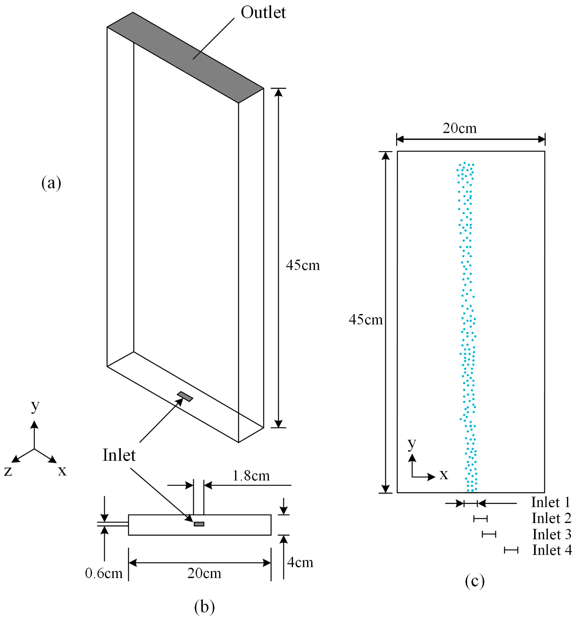
Figure 1. (a) 3D physical model, (b) inlet parameter, and (c) different inlet positions.
Computation 05 00038 g001
Figure 2. Mesh of case No. 1.
Computation 05 00038 g002
Figure 3. Comparison of the experimental and computational instantaneous gas hold-up results.
Computation 05 00038 g003
Figure 4. Grid used in the computational fluid dynamics (CFD) simulations: (a) bottom, (b) inlet, and (c) axial cross-section.
Computation 05 00038 g004
Figure 5. Comparison of the time-averaged velocity magnitude results along a vertical axis between the numerical simulation and particle image velocimetry (PIV) [21].
Computation 05 00038 g005
Figure 6. Time-averaged streamline at z = 0 m in the bubble column: (a) case 1 (NEW-0), (b) case 2 (NEW-0.025), (c) case 3 (NEW-0.045), (d) case 4 (NEW-0.06), (e) case 5 (NON-0), (f) case 6 (NON-0.025), (g) case 7 (NON-0.045), and (h) case 8 (NON-0.06).
Computation 05 00038 g006
Figure 7. Liquid velocity in the y-direction at z = 0 m at different heights in the bubble column: (a) 0.09 m and (b) 0.22 m.
Computation 05 00038 g007
Figure 8. Instantaneous horizontal velocity of the liquid phase at the monitoring points: (a) cases 1–4 and (b) cases 5–8.
Computation 05 00038 g008
Figure 9. Gas hold-up distribution at z = 0 m in the bubble column: (a) case 1 (NEW-0), (b) case 2 (NEW-0.025), (c) case 3 (NEW-0.045), (d) case 4 (NEW-0.06), (e) case 5 (NON-0), (f) case 6 (NON-0.025), (g) case 7 (NON-0.045), and (h) case 8 (NON-0.06).
Computation 05 00038 g009
Figure 10. Global gas hold-up.
Computation 05 00038 g010
Figure 11. Dynamic viscosity distribution of non-Newtonian liquid at z = 0 m in the bubble column: (a) case 5 (NON-0), (b) case 6 (NON-0.025), (c) case 7 (NON-0.045), and (d) case 8 (NON-0.06).
Computation 05 00038 g011
Figure 12. Comparison of the volume-averaged bubble diameter.
Computation 05 00038 g012
Table 1. Parameters of different calculation cases.
No. of Case12345678
Distance from inlet center to bubble column’s bottom center (m)00.0250.0450.0600.0250.0450.06
Liquid propertyNewtonianNon-Newtonian
Note: NEW-0/Non-0 mentioned in the title of graph means that the liquid property is Newtonian/Non-Newtonian and the distance from inlet center to the center of the bubble column’s base is 0 m.
Table 2. Gas hold-up values with different parameters.
Elements NumberTime Step Size (s)Max IterationsGas Hold-Up *
18720.01300.0058
33600.01300.0060
10,3950.01300.0065
22,1850.01300.0057
10,3950.01100.0064
10,3950.01500.0065
10,3950.02300.0064
10,3950.005300.0065
* The gas hold-up in the experiments was 0.0069.