Article

A New Method to Infer Advancement of Saline Front in Coastal Groundwater Systems by 3D: The Case of Bari (Southern Italy) Fractured Aquifer

by
Costantino Masciopinto
* and
Domenico Palmiotta
Consiglio Nazionale delle Ricerche, Istituto di Ricerca Sulle Acque, Reparto di Chimica e Tecnologia delle Acque, 5 via Francesco De Blasio, 70132 Bari, Italy
*
Author to whom correspondence should be addressed.
Computation 2016, 4(1), 9; https://doi.org/10.3390/computation4010009
Submission received: 30 November 2015 / Revised: 1 February 2016 / Accepted: 2 February 2016 / Published: 16 February 2016
(This article belongs to the Special Issue Advances in Modeling Flow and Transport in Porous Media)

Abstract

:
A new method to study 3D saline front advancement in coastal fractured aquifers has been presented. Field groundwater salinity was measured in boreholes of the Bari (Southern Italy) coastal aquifer with depth below water table. Then, the Ghyben-Herzberg freshwater/saltwater (50%) sharp interface and saline front position were determined by model simulations of the freshwater flow in groundwater. Afterward, the best-fit procedure between groundwater salinity measurements, at assigned water depth of 1.0 m in boreholes, and distances of each borehole from the modelled freshwater/saltwater saline front was used to convert each position (x, y) in groundwater to the water salinity concentration at depth of 1.0 m. Moreover, a second best-fit procedure was applied to the salinity measurements in boreholes with depth z. These results provided a grid file (x, y, z, salinity) suitable for plotting the actual Bari aquifer salinity by 3D maps. Subsequently, in order to assess effects of pumping on the saltwater-freshwater transition zone in the coastal aquifer, the Navier-Stokes (N-S) equations were applied to study transient density-driven flow and salt mass transport into freshwater of a single fracture. The rate of seawater/freshwater interface advancement given by the N-S solution was used to define the progression of saline front in Bari groundwater, starting from the actual salinity 3D map. The impact of pumping of 335 L·s−1 during the transition period of 112.8 days was easily highlighted on 3D salinity maps of Bari aquifer.

Graphical Abstract

1. Introduction

Groundwater over-abstractions typically can lower water table level and reduce freshwater fluxes, leading to severe saltwater intrusion problems in several coastal and metropolitan areas [1,2,3]. However, water supply is necessary for regional economic development and even for energy production. For instance, renewable sources of energy associated with the salinity gradient can be recovered in coastal areas where freshwater is mixed with saltwater. The techniques to produce electric energy from salinity gradient use the pressure-retarded reverse osmosis process [4] and associated conversion technologies. In addition, also geothermal energy production at low enthalpy should also increase at a rate of 3%–4% in Italy until 2020 [5]. Both geothermal low-enthalpy technology and the pressure-retarded reverse osmosis method require freshwater supplies (i.e., pumping) from coastal aquifers.
Subsequently, the subtraction of appreciable freshwater volumes from coastal aquifers cannot be always avoided and its real impact on groundwater should be adequately investigated. The salinity maps are useful tools for coastal groundwater management and they show how inland advancements of seawater may affect coastal aquifer quality. Chongo et al. [6] carried out an experimental work in Africa to define groundwater salinity variation map within the sedimentary formations of the Barotse sub-basin in the Western Province of Zambia. 39 boreholes were used to construct a database for the geological model development in this study area. The GEOSCENE 3D (I-GIS, 2016, I-GIS, Risskov, Denmark) [7] software was employed for visualizing, interpreting, editing and publishing geological data. Data derived from field measurements were analyzed using the SiTEM SEMDI (Hydrogeophysics-Group-1, 2001, University of Aarhus, Aarhus, Denmark) [8] and Res2Dinv (Geomoto, Penang, Malaysia) [9] software. In the study area the distribution of most boreholes was somewhat unidirectional and it resulted in data gaps that make geo-modeling quite difficult. For this reason, authors proposed the use of pseudo (i.e., imaginary) boreholes in order to reduce the data gaps. Other researchers [10] suggest the employment of empirical models such as the Archie’s law (1942) [11] to improve the best fit of experimental data (i.e., water electrical conductance) collected from wells. Lesch et al. [12] demonstrated the efficiency of the regression-based statistical method for predicting, at field scale, soil spatial salinity conditions, starting from rapidly acquired electromagnetic induction data. This regression model incorporates multiple measurements and their trends in order to increase the prediction accuracy of soil salinity maps.
In the present work a new method is presented for a rapid 3D visualization of saltwater-freshwater transition in coastal zone under new pumping stress conditions. The method requires field salinity measurements in boreholes and simulation results from two different flow models. The first model studies the steady groundwater flow in fractures by providing the Ghyben-Herzberg seawater/freshwater sharp interface toe position along the coast. Fracture transmissivity were derived from pumping and tracer (chlorophyllin) injection tests. The second flow model studies the transient density-driven flow of seawater into freshwater of a single fracture by means of the N-S equations. The result of the latter model was used to predict the transient advancement of saline front in fractures subjected to new pumping conditions.

2. Methodology

Groundwater flow modeling was addressed in a 3D set of horizontal and parallel fractures characterized by impermeable rock walls (Figure 1). Each horizontal fracture of the 3D set has a variable aperture in the x-y plane [13] of 7240 × 6300 m2. Pumping and/or injection tests carried out into Bari wells, allowed the identification of the average aperture of all fractures of the set at each well position in order to determine the experimental variogram of spatial aperture covariance. Experiments on model calibrations and validations have been extensively reported by Masciopinto [14], Masciopinto et al. [13,15], and Masciopinto and Palmiotta [16]. The flow solution given by the flow model yields the freshwater discharge along the top border of domain. This freshwater discharge was used to determine the Ghyben-Herzberg sharp (50%) freshwater/saltwater interface [14]. These results defined also the saline front position along the coast.
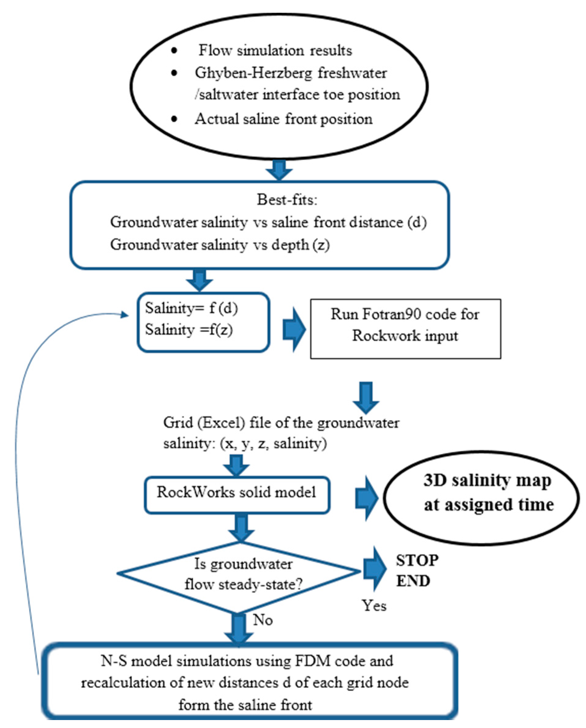
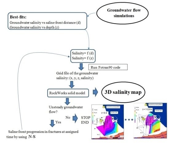
At the second step (Figure 2), the groundwater salinity into a generic borehole of the Bari aquifer was fitted as a function of the distance of the same borehole from the saline front. For this interpolation, salinity measurements in 25 boreholes of the Bari coastal aquifer (Southern Italy) at the same depth of 1.0 m below the water table were used. The resulting best-fit equation was used to convert the generic grid node position of the computational domain with respect to the saline front into the groundwater salinity concentration (at the depth of 1.0 m). Moreover, a further best-fit procedure was applied to the salinity profiles collected into 17 boreholes in order to estimate the groundwater salinity concentration with depth z below water table. These groundwater concentrations (i.e., discontinuous values) were used in RockWorks15 (RockWare Inc., Golden, CO, USA) to obtain a solid model (i.e., continuous values) useful to visualize groundwater salinity 3D map at Bari coastal aquifer.
Figure 1. (a) Parallel set of horizontal (x-y) fractures with permeability equivalent to the real fractured medium; (b) modeled fracture apertures in each single fracture of the set: the aperture variation in the x-y plane is obtained by means of the experimental variogram derived from results of well pumping (or injection) tests.
Computation 04 00009 g001
Figure 2. Flowchart of the applied methodology to produce transient 3D maps of the groundwater salinity.
Computation 04 00009 g002
Finally, the N-S solutions into a single fracture were used to define the inland progression of saline front into groundwater during saltwater-freshwater transition period due to a simulated new pumping, starting from the actual salinity data. The results produce groundwater salinity values (and 3D map), at each selected simulation time.
An alternative method to obtain the same groundwater salt concentrations on the freshwater-saltwater transition is application of specific type of software, such as HydroGeoSphere (Aquanty Inc., Waterloo, ON, Canada), or similar [17], which allows 3D simulations of density-driven flow system under transient conditions. Anyway the application of this type of models to discretely fractured media is very challenging [18] due to complexity of input data required to describe preferential flow pathways [19] and due to the unknown positions (and apertures) of actual fractures and their intersections, especially at a regional scale (>1000 m).

3. The Case Study and Field Tests

The Bari’s coastal land portion (Puglia region, southern Italy) (Figure 3) has a catchment surface of around 10,000 × 7000 m2 due to streams that flow into the Adriatic Sea. In this coastal area groundwater is confined within the limestone (Cretaceous) formation, and water flows in horizontal fractures in SW-NE direction, i.e., towards the coast. Geologically, the Bari aquifer is located in the Murgia region. In the tested area (coastal area of the Murgia region), rock permeability is low and discontinuous both horizontally and vertically. The geological sequence of layers observed during borehole drilling, from top downward, is Pleistocene sandstone (3–5 m thick), Cretaceous limestone (26 m thick), and Jurassic dolomite (>20 m thick). Murgia shows neo-tectonic sub-vertical fractures of the Mesozoic rocks that are relatively frequent and barely open or are sealed by calcspar and terra rossa (bulk density 1.26 ± 0.1 g/cm3). The Bari aquifer is not highly karstified. This means that calcite dissolution had taken place inside fractures of the Bari/IRSA aquifer, and an increase in hydraulic conductivity to 0.42 cm/s was found with respect to the quasi non-karstified limestone with 0.01–0.04 cm/s of hydraulic conductivity close (<1 km) to the sea coast.
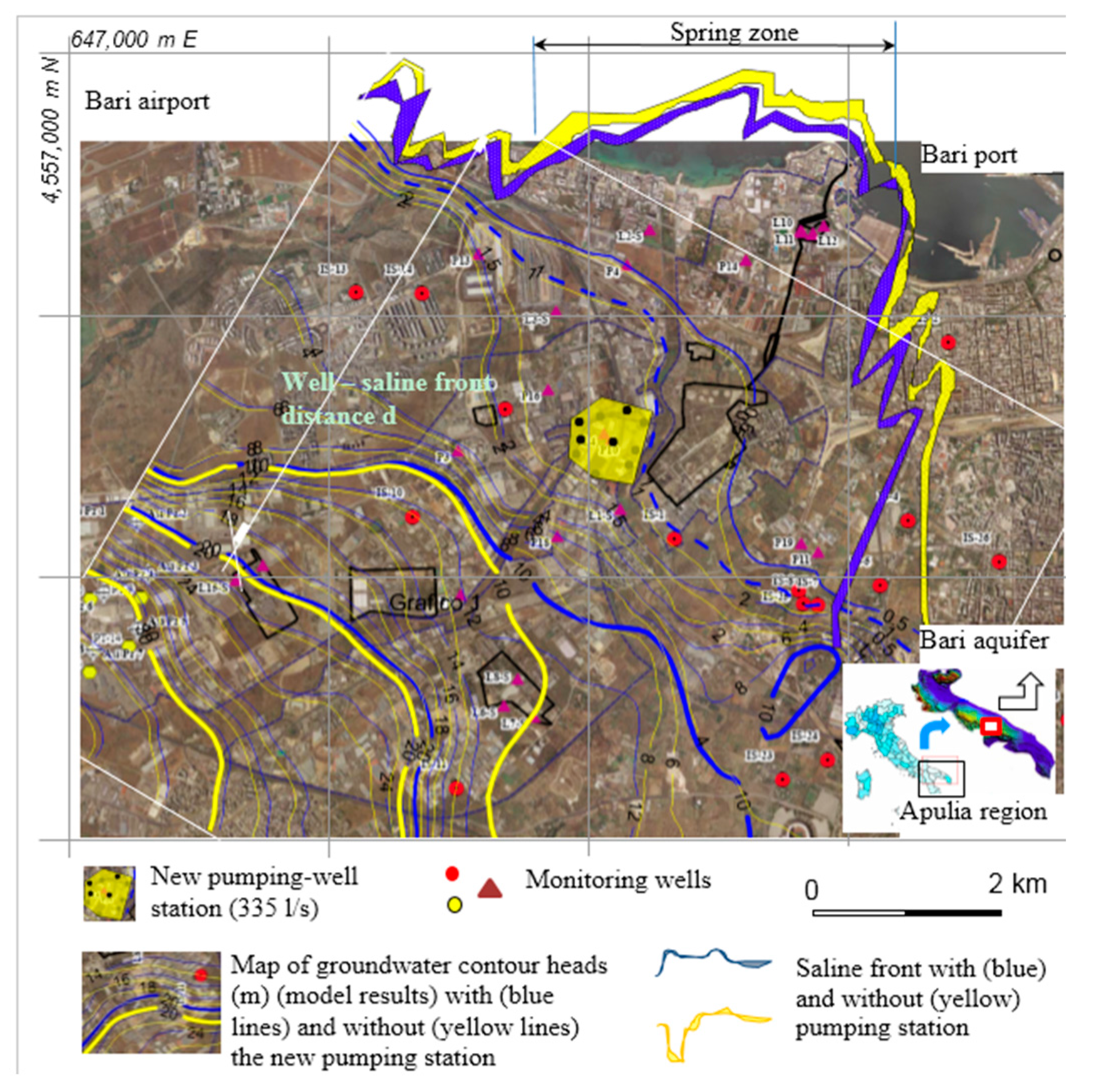
Figure 3. Spatial distribution of wells (red circles and tringles) and flow simulation results with distance d of each well from position of Ghyben-Herzberg saline front in groundwater. The yellow lines (and polygon) refer to actual groundwater flow simulation. The blue lines (and polygon) consider the flow modifications due to new pumping of 335 L·s-1. The blue dashed line is the contour head at 1 m.
Computation 04 00009 g003

3.1. Field Set Up

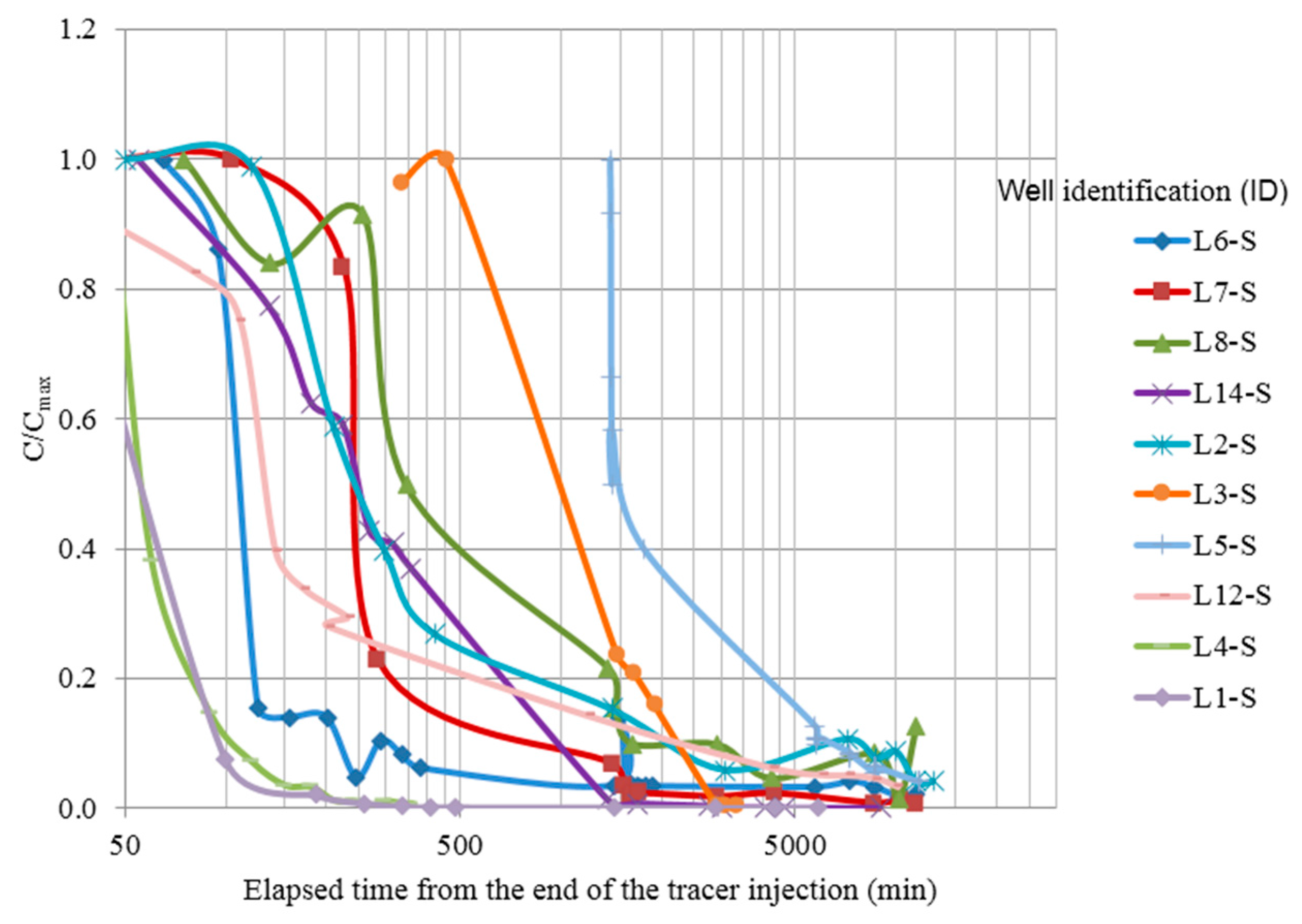
Groundwater macroscopic parameters such as transmissivity T [l2·t−1] (l stand for length; t stands for time) and hydraulic conductivity K [l·t−1] were determined by inverting the semi-analytical solution of Thiem’s equation. The results of 58 pumping tests and 10 tracer tests (Figure 4) carried out by IRSA on the Bari aquifer boreholes, were considered in this work. In particular, pumping (or injection) and tracer tests under undisturbed (or natural) gradient were carried out in order to estimate local values of both aquifer hydraulic transmissivity and groundwater specific discharge (see Table 1). The analytical solution of tracer (chlorophyllin) dispersion into the water was applied [13] to the breakthrough curves in Figure 4 in order to determine the horizontal water velocity in each borehole.
Figure 4. Breakthrough curves of relative tracer (chlorophyllin) concentrations during injection tests in ten boreholes of Bari aquifer.
Computation 04 00009 g004
Table 1. Network of monitored wells at the Bari fractured aquifer: Pumping and tracer test results.
Well IDCoordinates (UTM)Tracer TestInternal Diameter (m)Piezometric Head (m above Sea Level) January–February 2012Aquifer Hydraulic Transmissivity (m2/s)Ground Water Specific Discharge (m/day)
EN
P10652,892.84,553,271.3 0.300 4.4800.09
L1-S652,994.34,552,693.5X0.1804.2685.2780.6 × 10−3 ± 1.8 × 10−41.3
P11654,726.94,552,308.3 >1.01.2511.6110.02
P19654,580.14,552,382.9 >1.00.771.1100.02
P14654,093.34,554,883.8 0.0120.3110.3210.045
L2-S653,252.54,555,151.7X>1.00.5820.7220.047 ± 0.010.5
P4653,053.84,554,841.5 0.0120.2660.3860.06
L3-S652,431.04,554,429.8X>1.01.9032.1630.043 ± 0.022.6
P3651,569.24,553,208.7 0.3004.3215.4410.07
P16652,360.04,553,741.7 0.0142.6583.5380.09
L4-S652,850.94,553,352.7X0.3002.5353.4500.033 ± 0.032.2
P18652,442.44,552,454.1 0.200 6.9260.07
L5-S647,930.74,551,813.2X0.325 33.6493.0 × 10−3 ± 1.8 × 10−30.2
L8-S652,094.54,551,194.2X0.080 8.5320.02 ± 0.010.4
L7-S652,237.34,550,862.3X0.080 7.8800.5 × 10−2 ± 0.4 × 10−20.6
L6-S651,974.44,550,961.1X0.080 8.8920.11 ± 0.011.4
P13651,750.44,554,936.6 0.300 0.8070.02
L9654,682.24,555,123.7 0.100 0.7050.1
L10654,572.74,555,144.1 0.100 0.1670.01
L11654,588.54,555,126.1 0.100 0.3170.01
L12-S654,679.54,555,109.1X0.300 0.3600.01 ± 0.7 × 10−30.3
L13654,777.04,555,188.8 0.100 0.4181.2 × 10−5
L14-S649,860.64,552,197.6X0.080 34.3701.1 × 10−4 ± 5.3 × 10−50.6
L15649,623.84,552,059.7 0.080 35.2601.2 × 10−5
P2651,595.44,551,934.3 0.300 6.7600.025
X means that tracer test was also performed on the borehole.

3.2. Experiment Methodology

During pumping (or injection) tests the flow rate was changed from 1 to 3 L·s−1 and from 3 to 6 L·s−1, on average. In addition water table depth was simultaneously monitored (and recorded) by means of the pressure probe (mini-log data logger, SIM Instrument SNC, Milan, Italy). The flow rate of each pumping (or injection) was kept constant for about 2 h; at the end of the test, pumping was stopped and the rise (or decline, after an injection) in water depth was recorded during the recovery period.
For each tracer injection, 1 m3 of water was marked with 500 g of chlorophyll powder commercially sold as E141 hydro soluble or sodium copper chlorophyllin, which is usually used for foodstuffs such as pickles, ice creams, candies and fruit juices, and therefore it is not dangerous for human health. After mixing water and chlorophyllin powder in a tank of 1 m3 volume, the traced mixture was injected with a constant flow rate of around 2 L·s−1 into a borehole, using a submersible pump and a pipeline (3 inch internal diameter). The traced water was injected at an assigned water depth (3 m) for about 8 min. The injection pipeline was then removed and groundwater was sampled at regular time intervals via a sampling pump (Grundfos BTI/MP1, Downers Grove, IL, USA) placed at the assigned water depth of 3 m into the well. Each water sample was stored in a plastic (Polyvinyl chloride or PVC) black bottle and transported in the laboratory where samples were monitored for water absorbance. Groundwater was sampled as long as the background tracer value of 10−3 absorbance units (AU) [20] was again achieved in the well. During injection water depth was monitored and recorded using a pressure probe and the data logger (SIM Instrument, Milano, Italy). The measurement of tracer concentration in the borehole referred to a calibration curve previously determined in the laboratory using a spectrophotometer (HACH DR/2000, Hach Lange Srl, Lainate, Italy) at a frequency of 405 nm. Test results suggest an aquifer discretization of 80 smoothed (and parallel) fractures. In fact, as n [–] defines the effective aquifer porosity, it is the uniform ratio of the void-space per unit volume of aquifer and, in each cross-section, it will be:
n = i = 1 N f 2 b i B
where ∑2bi [l] is the sum of all horizontal fracture apertures of the aquifer column with unitary horizontal area (1 × 1 m2) and thickness B [l], while Nf [–] is the total number of the fractures of the parallel set (see Figure 1). Assuming that all fractures of the set have the same aperture of 1.3 mm, i.e., ∑2bi = Nf × 2b = n × B and for n = 0.35% and B = 30 m (see test results Table 1), Equation (1) suggests Nf = 80.

4. Groundwater Flow Simulation and Ghyben-Herzberg Interface Toe Position

At the regional scale (7200 × 6300 m2) every fracture belonging to the 3D parallel set (Figure 1) was discretized using a grid step size of Δx = Δy = 150 m (i.e., 49 × 43 grid nodes). The steady and non-uniform groundwater flow was addressed in a series of parallel and horizontal fractures, with each single fracture having a spatially variable aperture and impermeable rock matrix. The model implemented the approximated analytical radial flow solution to a well in order to determine the mean conductivity of aquifer fractures at each well position by using K = nb2/3 γw/µ, where γw [M·l−2·t−2] (M stands for mass) is the water specific weight and µ [M·l−1·t−1] is the dynamic water viscosity. The experimental variogram regarding the fracture apertures derived from well pumping tests was employed to perform the stochastic generation of apertures in each horizontal fracture belonging to the set. The discharge/head relationship in each fracture is defined as [15]
( φ i φ j ) = Q i j 2 [ f 2 g Δ y Δ x Δ y ( 1 ( 2 b i ) 3 + 1 ( 2 b j ) 3 ) ]
where f [–] is the friction factor derived from the Reynolds number; Qij [l3·t−1] is the flow rate of each fracture between two generic grid nodes i and j; Δx [l] and Δy [l] are the grid steps; and φ = pw [l] is the water head, whilst g [l·t−2] is the gravity acceleration. It should be noted that Equation (2) supports flow calculations at any Reynolds number. By imposing the continuity equation, i.e., ∑Qij = 0, in every grid node, a system of equations was defined. The over-relaxation method was applied to solve the system of equations after that the boundary conditions were assigned. The flow simulation results enabled calculations of the seawater/freshwater 50% sharp interface positions with respect to the coastline, by applying the Ghyben-Herzberg equation. Indeed, to predict the interface toe position L [l] with respect to the coastline, the resulting groundwater outflow was managed in order to calculate the length of intrusion for every position along the coast defines as [14]
L L d = K B 2 H s 2 2 δ γ × Q 0 L d = n b i 2 3 γ w μ ( δ γ × φ 0 ) 2 H s 2 2 δ γ × Q 0 i L d
where Ld [l] is the distance of the contour head φ0 (for instance 1 m) from the coastline given by flow simulation result; Hs [l] is the sharp interface depth at the outflow (usually set = 0); Q 0 i [l2·t−1] is the groundwater discharge along the coast predicted by model at grid node i; and δ γ = γ w / ( γ s γ w ) [–] is the ratio of the specific weights.
Equation (3) shows that the extension L L d of the sea intrusion is a function of both groundwater outflow and maximum freshwater thickness. Figure 3 saline fronts in groundwater before (in yellow) and after (in blue) a simulated new pumping of 335 L·s−1 (assuming that reinjections of pumped water are not allowed). Figure 3 shows how the new pumping changes the saline front position with respect to the coast. Simulation results provided a total decreases of 12% of freshwater Q 0 discharged into the sea, i.e., from 10.8 to 9.5 m3·day−1·m−1 in each fracture of the parallel set, due to new (or apparent) pumping wells. The maximum distance d of pumping wells from interface (see Figure 3) decreased of about 1000–1500 m, on average, due to new pumping.

Advancement of Saline Front in a Fracture Using N-S
The salt water advancement due to transient density-driven flow in a single fracture was investigated via the solution of the N-S equations. These solutions allowed the estimation of the time period required by saltwater to reach new Ghyben-Herzberg equilibrium due to simulated pumping. The governing N-S equations can be written by considering the salt mass and momentum conservation. In the Lagrangian framework can be written:
D ρ D t + ρ u α x α = 0
and
D ρ u α D t = σ α β x β + ρ g α  and  α , β = x , y , z
where indexes α and β denoted the generic spatial component following Einstein notations, ρ [M·l−3] is water density, and uα is the velocity [l·t−1] of the fluid particle; xα [l] and xβ [l] are two spatial position coordinates of the fluid particle (Einstein notation); gα [l·t−2] is the component of the gravity vector. The tensor component of the Newtonian stress component σαβ [M·t−2·l−1], which was applied to each particle subject to the pressure pδαβ [M·t−2·l−1] can be defined:
σ α β = p δ α β τ α β
where laminar and turbulent stress component τ [M·t−2·l−1] of the viscosity can be defined using [21,22]:
τ α β = { μ × [ ( u β x α + u α x β ) 2 3 δ α β u ] } + τ ¯ α β
where δαβ [–] is the Kroneker delta; τ ¯ α β is the average sub-grid stress due to the fluctuating variation of velocities around the averaged values during turbulent flows. Similarly, Reynolds stress can be determined by assuming the eddy viscosity theory (Boussinesq’s hypothesis), and by the Smagorinsky constant [23].
Some authors introduce also the Tait’s equation [24], i.e., the Equation of State, in order to complete the unknowns/equations balance.
However, when the first N-S equation is applied to a single computational cell of discretized water flow domain, water flow density remains constant by changing pressure due to water incompressibility and Equation (4) reduces to:
· u = 0
and cannot be used to estimate velocity due to its undetermined form. By using the projection method the velocity u* given by N-S conservation momentum Equation (5) is included in the following (Poisson) [25] equation:
u * = Δ t ( p )
in order to estimate the water pressure. In Equation (9) u* is the intermediate velocity whose value is based on the viscous stress. Equation (8) is then used in a finite difference model (FDM) [16] in order to estimate the pressure of water via a separate numerical calculation. In particular, the conjugate gradient numerical method was applied to solve Equation (8) in order to calculate the water pressure by forcing the flow divergence to zero. After that the water pressure was determined, the correct velocity is obtained by Equation (9). Thus, at the next time step, the N-S momentum conservation Equation (4) is solved again to calculate the new intermediate water velocity. Moreover, in order to account for flow density variations due to the saline front advancement in the FDM code, the velocity u* derived from Equation (5) was updated at each time step according to the new distribution of water densities into the cells of the fracture domain. This water density distribution due to mass salt flow advancement in the fracture was determined at every instant of the flow simulation by solving the salt advection and dispersion equation into the freshwater of the fracture, using a hydrodynamic dispersion coefficient of 10−9 m2·s−1. In this way in every cell of the domain the divergence of the salt mass flux in the x and z directions was predicted at each simulation time.
The N-S flow equations were solved in a horizontal fracture of Bari aquifer with 5 m of extent and 2b = 3 mm of aperture, which is the maximum fracture aperture derived from pumping-tests carried out on Bari wells. The computational domain x-z was discretized in cells of 0.3 mm × 50 mm of size, i.e., 10 × 100 cells. The transitory density-driven flow of seawater mixed with freshwater was performed assuming that the freshwater fracture, at the inlet section, is subjected to a constant salty water inflow at 35 g·L−1 of total concentration. Moreover, the reduction of 1.3 m3·day−1·m−1 of freshwater discharge Q0 in each fracture was also applied at the inflow section as the initial conditions during N-S simulations. Flow through the fracture cross-section (2b × 1 m2) was driven by a momentum (per unit volume) equal to 12,375 kg·m−2·day−1. This was defined by the product of the reduction of freshwater flowrate along the coast (from 102.9 to 90.5 m·day−1) (due to new pumping of 335 L·s−1) and the freshwater density (12.4 m·day−1 × 1000 kg·m−3). Furthermore, at t = t0 = 0, the salt density distribution in all cells of fracture was also imposed as initial condition.
The N-S code provided the time-dependent distribution of both water pressure and velocity in a fracture, caused by changes in water density due to salt water advancement due to the new pumping.
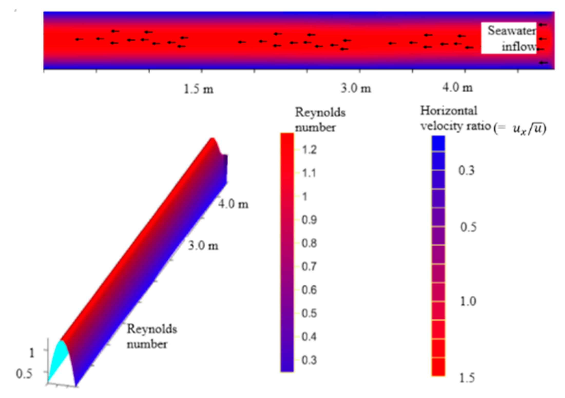
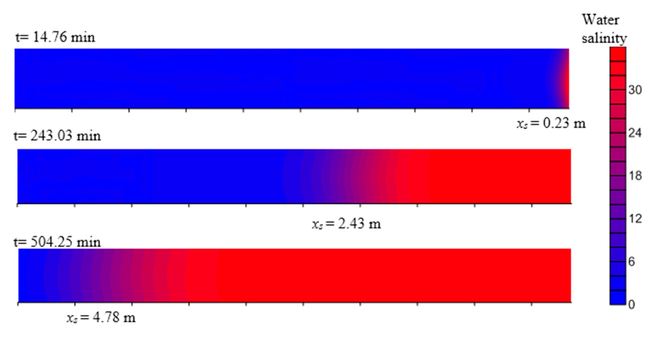
The FDM code results (see Figure 5 and Figure 6) produced an almost regular flow with a maximum central value of velocity (and Reynolds number) and, subsequently, in both pressure gradient and water density. This occurs because the diffusive/convective salt mass flux divergence decreases from the centerline to the border of the fracture. By using a PC with a single Intel Pentium(R) 32 bits, the FDM code required 1 h and 12 min run-time (CPU) to simulate a period of 792 min. N-S solutions provided information regarding the freshwater/seawater sharp interface positions xs [l] in the studied fracture at specific simulation time. Using twelve simulation run results the following linear equation was (0.99 of correlation) close-fitting in TableCurve2D:
x s ( t ) = C s + B s × t
where the position of salt water advancement in the fracture is dependent on time and two constants: Cs = 1.08 × 10⁻¹ m and Bs = 9.36 × 10⁻³ m·min−1 (or 13.3 m·day−1). The results of the N-S code simulations confirmed the strong influence of fracture aperture size on water velocity estimation. For a fracture with 3 cm aperture, the mean water velocity (and Reynolds number) may be 100 times higher than the value determined for a fracture with 3 mm aperture. The quasi linear trend of the saline front advancement given by Equation (10) well matches the temporal trend of the progression of toe positions given by [26] during simulations. The rate of seawater advancement given by the N-S code (i.e., 13.3 m·day−1) is close to the expected value (12.4 m·day−1), which is driven by the prescribed momentum. Using these N-S solutions, maximum elapsed time from the start of pumping to reach the new position of freshwater/saltwater sharp interface in the Bari groundwater is equal to 112.8 day (i.e., 1500 m/(13.3 m·day−1)). Material concerning the advancement of sea movement intrusion is very useful for groundwater management practices of coastal aquifers [26,27,28].
Figure 5. N-S solutions in a fracture (of aperture 2b = 3 mm, 2b stands for the fracture aperture in the manuscript.) of the Bari aquifer. The rate of saline front advancement was used to determine the effects of new pumping of 335 L·s−1 on the freshwater/saltwater transition zone in coastal aquifers.
Computation 04 00009 g005
Figure 6. N-S solution at time t = 243.03 min from the beginning of the new pumping of 335 L·s−1: horizontal flow velocity magnitude map due to freshwater/saltwater mixing in the fracture, and Reynolds number distribution.
Computation 04 00009 g006

5. Conversion of Distances from Interface into Groundwater Salinity Data

The conversion of each grid node distance from saline front into groundwater salinity concentration required two data sets, namely: (i) field salinity monitored in wells; and (ii) data from groundwater flow simulations.

5.1. Field Monitored Data

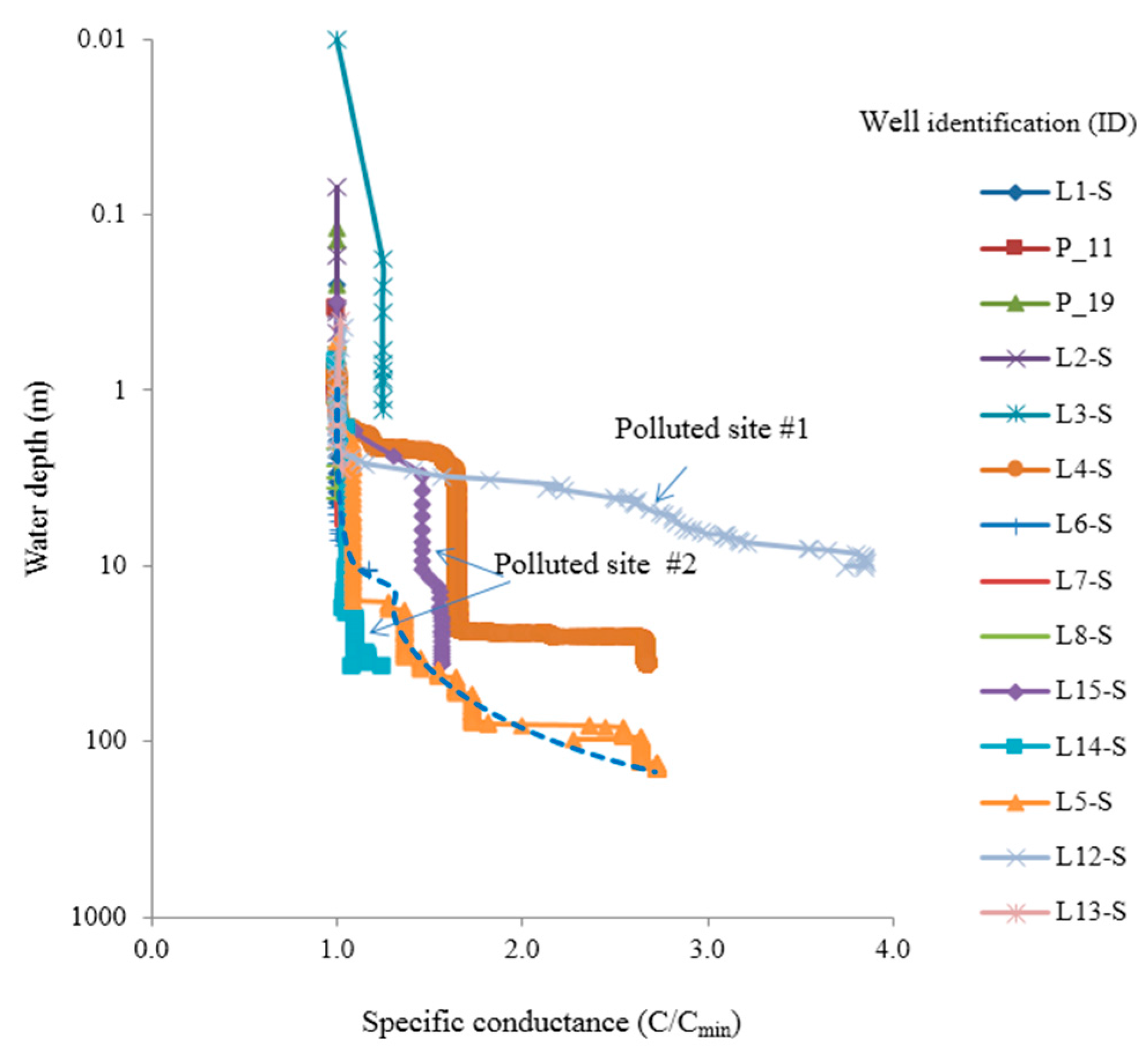
Seventeen wells of the Bari aquifer were monitored for water depth and specific water conductance. These measurements were carried out using multiparameter mini-probes (OTT Hydrolab, Kempetn, Germany) Hydrolab-DS5 and OCEAN SEVEN 315 (IDRONAUT Srl, Brugherio, Italy). The latter one also provided dissolved the water oxygen concentration, which varied from 3.0 mg·L−1 (at the surface) to 0.3 mg·L−1 or less (at 37 m depth) in Bari’s wells, and the water temperature. Each probe was previously calibrated in the laboratory in order to directly provide proper values of water salinity, temperature, pressure and dissolved oxygen vs. water depth. The relative monitored water specific conductance in 14 boreholes is displayed in Figure 7, where C/Cmin is the ratio of each measurement to the minimum recorded value at each specific borehole location. Figure 7 presents anomalous salinity trends in the polluted sites that are characterized by high water temperatures.
Figure 7. Relative specific conductance vs. water depth in 14 boreholes of the Bari aquifer positioned at different distance from Ghyben-Herzberg freshwater/sweater (50%) sharp interface position (Winter 2012) and best-fit equation (dashed line).
Computation 04 00009 g007

5.2. Ghyben-Herzberg Data

At first step, an interpolation in TableCurve2D provided the best equation (correlation coefficient of 0.92–0.9) which fits groundwater salt concentrations measured in 25 boreholes at depth of 1.0 m below water table versus the modeled distance d of each borehole from the saline front into groundwater provided by Ghyben-Herzberg theory (see yellow polygon in Figure 3).
C s a l t = C s 0 + A s [ exp ( d D s ) ]
where, for d ≤ 1500 m, the best fit constants are Cs0 = 1.54 g∙L−1, As = 12.02 g∙L−1 and Ds = 592.65 m. At distances d > 1500 m the following best-fit equation:
C s a l t = [ exp ( G s I s d ) ]
it was preferred to Equation (11), where Gs = 2.54 log(g·L−1) and Is = 0.04177 log(g·L−1∙m−0.5) are the best fit constants.
The significance of the above interpolation is that Equations (11) and (11a) enable the calculation of the salinity at depth z = 1.0 below water table at every generic position (x, y) of the computational domain, on the basis of field monitored data and distance d given by groundwater flow model solution.
Thus, a second interpolation of groundwater salinity concentrations measured in wells as a function of the water depth was performed. In particular, the use of TableCurve2D enabled the acquisition of groundwater salt concentrations with depth z at each generic location (x, y), using the best-fit curve displayed (dashed line) in Figure 7 (with correlation coefficient of 0.93).
C s a l t = C 0 × [ E s ( z ) F s ( z ) ]
where Es and Fs are two dimensionless interpolating functions with polynomial form:
E s ( z ) = 0.99 + 2.26 10 3 z 5.32 10 4 z 2 + 4.38 10 6 z 3
F s ( z ) = 1 1.80 10 2 z 1.07 10 5 z 2 + 1.03 10 6 z 3
where z [l] is water depth into borehole and C0 is minimum salinity value at the specific borehole location. Equation (12) is valid up to a water depth of 140 m. Moreover, the following best-fit function (correlation coefficient of 0.93) could also replace Equation (12):
C s a l t = C 0 × { 1.55 [ 1 + e r f ( z 5.6 5800 ) ] 0.5 }
The significance of this interpolation is that Equation (12) or (12c) enables the calculation of the salinity with depth below water table at every generic position of the computational domain.
Once Equations (11) and (12) were determined, a FORTRAN90 (Visual FORTRAN Professional Edition 5.0.A, Microsoft Developer Studio 97, Microsoft Italia, Peschiera Borromeo (MI), Italy) code was used to perform groundwater salinity estimations. All grid-node positions of computational domain with respect to the freshwater/seawater interface were then converted to groundwater salinity data. A 3D file of 21,070 salt groundwater concentrations was obtained by using 10 grid steps of 10 m in z direction. This file was elaborated using RockWorks15 in order to determine the solid model of actual groundwater salinity, suitable for 3D map visualization. The reliability of this conversion method was quantitatively tested (Table 2) by comparing measured and predicted values at three different depths. The average uncertainty of these estimations is about 20% with respect to the mean salinity (=1.53 g·L−1) (see Table 2) at depth of 1 m below water table and it may be reduced by increasing the number of boreholes for salinity measurements.
Table 2. Comparison between modelled (Mod) values of groundwater salinity (i.e., Rockwork15 input data at t = 0) and measurements (Mea) at three water depths into boreholes of the Bari aquifer. SD stands for the standard deviation between measured and modelled values.
ID BoreholeActual (Winter 2012) Groundwater Salinity (g·L−1) at Different Water Depths
1 m11 m31 m
ModMea±SDModMea±SDModMea±SD
L1-S0.91.540.461.061.650.411.31
P112.762.990.163.14 3.9
P193.753.710.034.27 5.29
L2-S3.122.630.343.55 4.39
L3-S2.113.400.912.4 2.97
L40.981.050.051.11.720.441.382.770.98
L8-S0.50.710.150.52 0.65
L7-S0.50.580.060.6 0.74
L6-S0.50.670.120.520.780.190.65
L92.021.540.342.3 2.85
L14-S0.930.590.241.060.560.351.311.030.20
L15-S0.930.860.051.060.950.081.311.750.31
L5-S0.50.630.090.520.680.120.651.500.60
L122.020.561.032.32.260.032.85
Mean 1.53±0.32 1.23±0.23 1.76±0.52

5.3. Data from Solutions of N-S Equations

At third step, the same FORTRAN90 code previously applied was implemented applying Equation (10) to update the salinity concentrations in each grid node of computational domain at three different simulation times of 30, 75 and 112.8 days. The saline front displacement during time is given by N-S solutions, by determining the new grid node positions with respect to the salinity front. In particular, as input for this calculation, 49 distances of the top border of domain from the salinity front were provided at each simulation time. A control on the maximum distance calculated was imposed into the FORTRAN90 code in order to avoid that the advancement of the saline front may exceed the distance provided by flow model (i.e., blue polygon) plotted in Figure 3. The significance of this calculation is that it enables the estimation of groundwater salinity concentrations according to the advancement of salinity front in groundwater fractures during a new pumping obtained by solutions of the Navier-Stokes equations. The results provide 3D solid models in RockWorks15. 3D maps of Figure 8 show actual salinity of Bari coastal aquifer and its progression as the consequence of the constant new simulated pumping of 335 L·s−1.
Figure 8. (a) 3D map of groundwater salinity during winter 2012 (t = 0 day) and its comparison with groundwater salinity maps after (b) 30; (c) 75 and (d) 112.8 days of a simulated continuous pumping of 335 L∙s−1.
Computation 04 00009 g008

6. Discussion and Conclusions

A new method to infer saline front advancement in a fractured coastal aquifer was applied to Bari groundwater. Results visualize the 3D maps of groundwater salinity concentrations, at different simulation times, due to the impact of an apparent pumping of 335 L·s−1. The 3D maps are useful tools for coastal groundwater management and show how over-abstractions may affect groundwater salinity changes. The same method can be applied to others aquifers with discrete fractures and it requires two data sets: (i) field salinity data in boreholes (i.e., logs); and (ii) results of groundwater flow model simulation to represent actual 3D maps of aquifer salinity. Moreover, solutions of the N-S equations in a fracture can provide the rate (on average) of saline front advancement in fractures during time. This result allows updates of actual salt concentrations, by defining 3D salinity maps at specific simulation times during a new pumping. Although mapping based on the sharp interface approach is not representative of real conditions of the salt mass transport in fractures, the salinity front positions at the initial and final stage of the simulated pumping stress condition in this method, take into account for the real flow conditions in the fractured aquifer. Moreover, by including approximations due to the interpolation stages (correlation coefficients >0.92–0.93) authors have estimated the 20% of uncertainty of results at the Bari aquifer. This uncertainty established an acceptable distance of results from reality.
In the present work groundwater flow modeling was based on aquifer transmissivity values derived from pumping and tracer (chlorophyllin) injection tests carried out during winter 2012. At specific sites, a minor number (<30) of monitoring wells may increase limitations of results, and the uncertainty of the presented method.
The presented method is an alternative to the application of the 3D unsteady density-driven flow models at a regional scale, which may present computational limitations in discrete fractured aquifers due to complexity of input data required to describe preferential flow pathways and the unknown position (and aperture) of the fractures and their intersections, especially at a regional scale. Moreover, conventional meshed models based on finite elements, finite differences or boundary elements, are inappropriate for flow and transport simulations in fractured aquifers, i.e., not continuous porous media. This is due to impossibility to define a representative elementary volume (REV) of appropriate size in a fractured (or very heterogeneous) aquifer.
Data regarding the seawater front advancement in the Bari aquifer are highly suitable for groundwater management of coastal aquifers. Results suggest an elapsed time of 112.8 days to achieve the new Ghyben-Herzberg interface equilibrium position, starting from the beginning of the new pumping of 335 L·s−1.

Acknowledgments

This research was supported by Regional Authority under the program for groundwater remediation of polluted sites in the industrial area of Bari. Authors are very grateful to Leonardo Castellano (MATEC, Italy) which implemented the N-S solutions into the FDM code.

Author Contributions

Costantino Masciopinto conceived and designed the experiments, wrote the software and the paper; Domenico Palmiotta performed the experiments, contributed reagents/materials/analysis tools, analyzed the data.

Conflicts of Interest

The authors declare no conflict of interest.

References

  1. Barlow, P.M.; Reichard, E.G. Saltwater intrusion in coastal regions of North America. Hydrogeol. J. 2010, 18, 247–260. [Google Scholar] [CrossRef]
  2. Goswami, R.R.; Clement, T.P. Laboratory-scale investigation of saltwater intrusion dynamics. Water Resour. Res. 2007. [Google Scholar] [CrossRef]
  3. Essink, G.H.P.O. Salt water intrusion in a three-dimensional groundwater system in The Netherlands: A Numerical Study. Transp. Porous Media 2001, 43, 137–158. [Google Scholar] [CrossRef]
  4. Panyor, L. Renewable energy from dilution of salt water with fresh water: Pressure Retarded Osmosis. Desalination 2006, 199, 408–410. [Google Scholar] [CrossRef]
  5. Buonasorte, G. Development of geothermal energy in Italy until 2008 and short-term prospects, Ferrara (I). In Proceedings of the Congresso Internazionale: La Geotermia in Italia e in Europa. Quale futuro?—GEO THERM EXPO2009, Ferrara, Italy, 23 September 2009.
  6. Chongo, M.; Wibroe, J.; Staal-Thomsen, K.; Moses, M.; Nyambe, I.A.; Larsen, F.; Bauer-Gottwein, P. The use of Time Domain Electromagnetic method and Continuous Vertical Electrical Sounding to map groundwater salinity in the Barotse sub-basin, Zambia. Phys. Chem. Earth 2011, 36, 798–805. [Google Scholar] [CrossRef]
  7. I-GIS. GeoScene3D—Modelling and Visualization of Geological Data, Risskov, Denmark (DK). Available online: http://www.i-gis.dk/GeoScene3D (accessed on 3 February 2016).
  8. Hydrogeophysics-Group-1. Getting Started with SiTEM and SEMDI; Denmark University of Aarhus: Aarhus, Denmark, 2001. [Google Scholar]
  9. Geomoto Software. Res2Dinv v. 3.54 for Windows 98/Me/2000/NT/XP, Gelugor, Penang, Malaysia. Available online: http://www.geoelectrical.com (accessed on 3 February 2016).
  10. Mullen, I.; Kellet, J. Groundwater salinity mapping using airborne electromagnetics and borehole data within the lower Balonne catchment, Queensland, Australia. Int. J. Appl. Earth Obs. Geoinform. 2007, 9, 116–123. [Google Scholar] [CrossRef]
  11. Archie, G.E. The electrical resistivity log as an aid in determining some reservoir characteristics. Trans. Am. Inst. Mech. Eng. 1942, 146, 54–67. [Google Scholar] [CrossRef]
  12. Lesch, S.M.; Strauss, D.J.; Rhoades, J.D. Spatial prediction of soil salinity using electromagnetic induction techniques 1. Statistical prediction models: A comparison of multiple linear regression and cokriging. Water Resour. Res. 1995, 2, 373–386. [Google Scholar] [CrossRef]
  13. Masciopinto, C.; la Mantia, R.; Chrysikopoulos, C.V. Fate and transport of pathogens in a fractured aquifer in the Salento area, Italy. Water Resour. Res. 2008. [Google Scholar] [CrossRef]
  14. Masciopinto, C. Simulation of coastal groundwater remediation: The Case of Nardò Fractured Aquifer in Southern Italy. Environ. Model. Softw. 2006, 21, 85–97. [Google Scholar] [CrossRef]
  15. Masciopinto, C.; Volpe, A.; Palmiotta, D.; Cherubini, C. A combined PHREEQC-2/parallel fracture model for the simulation of laminar/non-laminar flow and contaminant transport with reactions. J. Contam. Hydrol. 2010, 117, 94–108. [Google Scholar] [CrossRef]
  16. Masciopinto, C.; Palmiotta, D. Relevance of solutions to the Navier-Stokes equations for explaining groundwater flow in fractured karst aquifers. Water Resour. Res. 2013. [Google Scholar] [CrossRef]
  17. Walther, M.; Delfs, J.O.; Grundmann, J.; Kolditz, O.; Lied, R. Saltwater intrusion modeling: Verification and Application to an Agricultural Coastal Arid Region in Oman. J. Comput. Appl. Math. 2012, 236, 4798–4809. [Google Scholar] [CrossRef]
  18. Werner, A.D.; Bakker, M.; Post, V.E.A.; Vandenbohede, A.; Lu, C.; Ataie-Ashtiani, B.; Simmons, C.; Barry, D.A. Seawater intrusion processes, investigation and management: Recent Advances and Future Challenges. Adv. Water Resour. 2013, 51, 3–26. [Google Scholar] [CrossRef]
  19. Masciopinto, C.; Palmiotta, D. Flow and Transport in Fractured Aquifers: New Conceptual Models Based on Field Measurements. Transp. Porous Media 2012. [Google Scholar] [CrossRef]
  20. Mehta, A. Ultraviolet-Visible (UV-Vis) Spectroscopy—Derivation of Beer-Lambert Law. Available online: http://pharmaxchange.info/press/2012/04/ultraviolet-visible-uv-vis-spectroscopy-%E2%80%93-derivation-of-beer-lambert-law/ (accessed on 3 February 2016).
  21. Chaniotis, A.K.; Frouzakis, C.E.; Lee, J.C.; Tomboulides, A.G.; Poulikakos, D.; Boulouchos, K. Remeshed smoothed particle hydrodynamics for the simulation of laminar chemically reactive flows. J. Comput. Phys. 2003, 191, 1–17. [Google Scholar] [CrossRef]
  22. Gesteira, M.G.; Rogers, B.D.; Dalrymple, R.A.; Crespo, A.J.C.; Narayanaswamy, M. SPHysics v2.0, January 2010: Open-Source Smoothed Particle Hydrodynamics Code. Available online: http://wiki.manchester.ac.uk/sphysics/index.php (accessed on 3 February 2016).
  23. Meyers, J.; Geurts, B.J.; Baelmans, M. Optimality of the dynamic procedure for large-eddy simulations, American Institute of Physics. Phys. Fluids 2005. [Google Scholar] [CrossRef] [Green Version]
  24. Becker, M.; Teschner, M. Weakly Compressible SPH for Free Surface Flows. In Proceedings of the Euro graphics/ACM SIGGRAPH Symposium on Computer Animation, Aire-la-Ville, Switzerland, 3–4 August 2007.
  25. Boersma, B.J. A 6th order staggered compact finite difference method for the incompressible Navier-Stokes and scalar transport equations. J. Comput. Phys. 2011. [Google Scholar] [CrossRef]
  26. Watson, T.A.; Werner, A.D.; Simmons, C.T. Transience of sea water intrusion in response to sea level rise. Water Resour. Res. 2010. [Google Scholar] [CrossRef]
  27. Yechieli, Y.; Shalev, E.; Wollman, S.; Kiro, Y.; Kafri, U. Response of the Mediterranean and Dead Sea coastal aquifers to sea level variations. Water Resour. Res. 2010. [Google Scholar] [CrossRef]
  28. Zlotnik, V.A.; Robinson, N.I.; Simmons, C.T. Salinity dynamics of discharge lakes in dune environments: Conceptual Model. Water Resour. Res. 2010. [Google Scholar] [CrossRef]