Abstract
Calculations testing can be effectively used in the construction of discrete self-checking devices. Calculations testing is based on the parity and self-duality of the calculated functions. This can be used for modern blocks and nodes of control systems for responsible technological processes. However, its use has a number of features that must be considered when building concurrent error-detection circuits. The authors used methods of discrete mathematics and Boolean algebra as well as technical diagnostics of discrete systems to investigate the problem of ensuring the testability of the parity encoder. Theorems on the testability of convolution functions modulo 2 are proved. Considering these theorems allowed the authors of the article to propose a method for synthesizing CED circuits. This method increases the testability of the encoder for parity. This method is based on the use of two diagnostic signs at once. The first sign is that the code words belong to the parity code. The second is the self-dual control function in the concurrent error-detection circuit. This method is guaranteed to increase the testability of the parity coder compared to using one of the diagnostic signs for calculations testing. Experiments with testing discrete devices have shown the effectiveness of the organization structure of the concurrent error-detection circuit that we developed. The theorems that we proved form the basis of proof of similar provisions for the use of other linear codes in the synthesis of concurrent error-detection circuits. Our proposed solutions with calculations testing based on two diagnostic signs should be used in the synthesis of discrete systems. Discrete systems should be self-checking and have improved testability indicators.
1. Introduction
One of the strategies in constructing highly reliable and low-maintenance discrete control systems is to endow their blocks and nodes with the properties of self-checking and self-testing [1,2,3,4]. Such devices are created considering the possibility of constantly checking the correctness of the values of the functions they calculate and, indirectly, considering the absence of faults in the internal structures. The methods of synthesis of self-checking discrete devices are quite well developed [5,6]. They are based on the use of structural, data, and time redundancy methods for hardware and/or software, as well as the use of sabotage protection [7]. Examples of the use of self-checking discrete systems are control complexes of microelectronic and microprocessor systems for railway signaling and interlocking systems [8,9] or on-board control systems in aviation [10,11].
The very property of self-checking in the construction of discrete systems can be implemented at various levels. These levels can be at the microelectronics level. They can also be at the level of individual blocks and nodes and even entire ready-made functional blocks and systems [12,13]. If we talk about individual devices within discrete systems, then self-checking implementations can be built at the component levels. They can be also for the entire device as a whole. For example, if an automatic model of a discrete device is used, the inputs and outputs of the internal memory elements and the output data can be encoded. They can be encoded in it in any way, for example, binary redundant code. This will make it possible to monitor the correctness of calculations testing in the process of performing their functions. This is due to the use of testers or detectors of these codes. Another way to implement a self-checking device with an automatic model of its description is to retrofit the blocks with concurrent error-detection (CED) circuits [14]. These are also synthesized using the properties of any binary redundant codes or special classes of Boolean functions [15]. This makes it possible, without introducing internal redundancy, to ensure calculations testing at the outputs of the state machine during its operation. Both approaches lead to the use of redundancy and sabotage protection methods. In addition, they are associated with an increase in the complexity of the technical implementation of devices. However, the self-checkability of structures comes at a price, affecting the ability to detect faults and errors in calculations in a timely manner.
This article was written by the authors based on the results of research on methods for synthesizing self-checking discrete devices. It is based on the properties of redundant uniform block codes and self-dual Boolean functions. The authors present the results of research on the implementation and functioning of the CED circuit organization structure for discrete devices as described in [16,17,18]. This structure is based on using a parity compression circuit and converting the parity function into a self-dual Boolean function. The original researchers called this method of organizing calculations testing the method of “self-dual parity”. In their article, the authors show the main advantages of this method of CED circuit synthesis. They also note its important disadvantages and propose a new method for CED circuit synthesis—synthesis of a circuit with calculations testing based on two diagnostic signs—addressing the disadvantages of the known method.
2. General Research Approaches and Methodology
Let us imagine a discrete diagnostic object in the form of a device similar to a “black box”. Let us assume that it is impossible to know its structure. But one can only observe the values at its outputs at any given time. The sets of argument values <X> = <xt xt−1 … x2 x1> are applied to the device inputs. Their total number is 2t. The values of the Boolean functions f1(X), f2(X), …, fm−1(X), fm(X) describing its outputs are calculated on each such set. The device’s response to all sets of argument values and generated Boolean vectors <fm(X) fm−1(X) … f2(X) f1(X)> is known.
Stuck-at faults and errors occur during the operation of the device in question. They lead to distortion of the values of the functions f1(X), f2(X), …, fm−1(X), fm(X) when input sets of argument values <X> = <xt xt−1 … x2 x1>. Moreover, the structure of the diagnostic object is checking, or self-testable. This means that for any fault from a given model, there is at least one set <xt xt−1 … x2 x1> on which the true values of the functions f1(X), f2(X), …, fm−1(X), fm(X) are distorted. This allows one to detect faults.
We will use time and structural redundancy to detect faults. To do this, all concurrent signals at the inputs and outputs of the device are in the vectors <xt xt−1 … x2 x1> and <fm(X) fm−1(X) … f2(X) f1(X)>. We will make them consistent by using the data inversion method [16,17,18]. This requires the installation of a generator G of straight-angle pulses with a duty cycle of 50%. Its output is connected to the first inputs t of two-input addition gates modulo 2 (XOR). In addition, input variables are supplied to the second inputs of these devices. Thus, binary signals 0 and 1 are transformed into pulse sequences 0101…01 and 1010…10. The vectors <xt xt−1 … x2 x1> begin to be generated as alternating vectors in a pair of a supplied effective vector and a check vector that is orthogonal to it in all variables. In other words, pairs of inverse combinations arrive at the device’s inputs. This property is precisely used to calculations testing.
The well-known [16,17,18] CED circuit structure of the “self-dual parity” uses a circuit for compressing signals from the diagnostic object by parity. It also uses the correction of the resulting value on each set of argument values to a value belonging to some self-dual function. The self-duality check is carried out due to the property of a self-dual function–on inverse sets it takes on opposite values [19]. It is precisely these opposite values that the self-dual checker examines.
We will further explore the features of the functioning of the CED circuit with signal compression by parity and correction of the resulting set to obtain a self-dual function. We will show the advantages and disadvantages of this structure. In addition, we will propose a way to eliminate these disadvantages.
Figure 1 shows a flow chart of the algorithm demonstrating the research plan. The task is divided into five main blocks. The first process implements the task of analyzing the properties of self-dual functions through an analysis of the schematic implementation of the parity coders. Here, the features of linear Boolean functions are analyzed; they are simultaneously self-dual. The second process is aimed at analyzing the causes of the violation of the self-duality property of the signal though analysis using the signal correction method fixed in the CED circuit. Here, it is important to find a pattern in the conditions under which the faults of the encoder elements are masked. The third process is related to the analysis of error detection features during calculations testing. The calculations testing are monitored using parity code and the self-duality of the signal in the CED circuit. It is established how the faults of the parity code encoder are covered. The fourth process demonstrates experimental research using the example of the simplest diagnostic object. It also confirms the theoretical positions formulated by the authors. The fifth process contains conclusions and recommendations on the practical application of the results obtained by the authors.
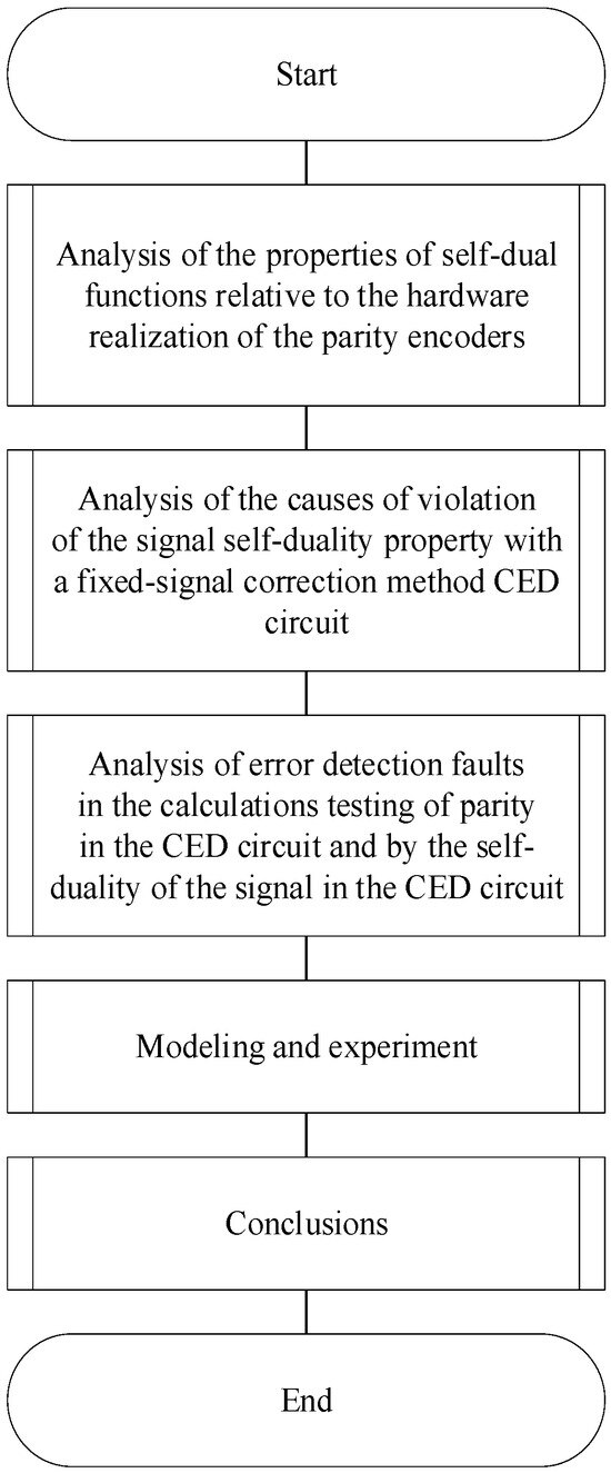
Figure 1.
Flow chart of the research algorithm.
3. Calculations Testing Based on Self-Duality with Compression of Signals from the Diagnostic Object by Parity
The structure of the CED circuit organization is shown in Figure 2.
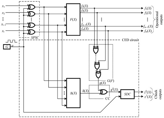
Figure 2.
The structure of the CED circuit organization with signal-compressing circuit by parity and calculations testing based on the self-duality of a Boolean function. In Figure: F(X)—diagnosis object, G—generator, G(F)—parity code encoder, Δ(X)—correction function calculation circuit, CC—correction circuit, SDC—self-dual checker, SPSC—signal to pulse sequence converter.
The parallel signals from the inputs x1, x2, …, xt−1, xt in the structure of Figure 2 are converted into pulse sequences. The conversion takes place using a specialized signal-to-pulse sequence converter (SPSC). It includes a cascade of t two-input XOR gates, the first inputs of which are supplied with variables x1, x2, …, xt−1, xt, and the second with a sequence of pulses a generated by a generator G. This allows the structure to function in a pulsed mode on pairs of vectors.
The signals f1(X), f2(X), …, fm−1(X), fm(X) calculated on each set of argument values <xt xt−1 … x2 x1> by block F(X) are fed to the inputs of the parity code encoder G(F). The value of the function is calculated at the outputs of the encoder:
The resulting function generates a parity bit. However, it is not this sign that is tested in the structure but rather the self-duality of the function formed in the CED circuit. The function g(X) itself is not self-dual in the general case. To obtain a self-dual function gδ(X) from it, the correction circuit (CC) transforms the value of the function g(X) using the following formula:
where δ(X) is the signal correction function calculated by the Δ(X) block.
Next, the value of the function gδ(X) is monitored by the self-dual checker using the SDC device [20]. The self-duality checker also works when using a clock signal from the G generator. This structure is shown in Figure 3.
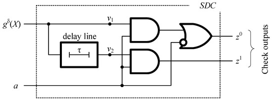
Figure 3.
The structure of the self-dual checker.
The SDC captures a two-rail signal <01> or <10> at outputs z0(X) and z1(X) when a self-dual signal is received at the inputs. A violation of non-two-rail indicates either internal SDC faults or a violation of the self-duality of the signals at its inputs. The last event occurs when there are faults or errors in calculations at the outputs of the remaining components of the CED circuit (or the diagnostic object). This is how faults in the described structure are fixed.
As noted above, the structure of Figure 2 functions when pairs of inverse combinations are applied to the inputs, which are formed by sets of argument values. The first combination is an effective one. The second is a check one.
The structure shown in Figure 2 has the following key feature: the difference from the traditional CED circuit with calculations testing of parity [21] is the use of Boolean correction signal (BCS) from the parity signal-compressing circuit. It is possible to build a huge number of blocks for calculating the function δ(X) of signal correction. Among them, one can choose the implementation of the Δ(X) block, which will have the lowest value of complexity for the technical implementation. The number of ways to transform a single parity function g(X) into a self-dual function gδ(X) on 2t sets of argument values is equal to . For this number, the simplest option can be selected.
Any errors at the outputs of the diagnostic object are detected with the described method of organizing calculations testing. It distorts only one function value on the supplied pair of argument value sets. If the error appears immediately on two sets of a pair, it is masked and not detected. In [17], it was shown that the use of the structure makes possible a slight deterioration in detection abilities by an average of 1.7%. This value is calculated in comparison with traditional parity testing. The structure is shown in Figure 2. Experiments were conducted with the MCNC Benchmarks test combination circuit. Structural redundancy is reduced by an average of 60% compared to traditional parity testing. This is a significant advantage of using a computational testing structure based on self-duality with the pre-compression of signals from the diagnostic object using the parity function.
4. Testability Theorems of the Compression Circuit in the Structure of the Concurrent Error-Detection Circuit
The structure of the compression circuit uses a device that converts signals f1(X), f2(X), …, fm−1(X), fm(X) according to Formula (1). This device is synthesized based on a linear Boolean function.
Theorem 1.
A linear Boolean function will be self-dual if it significantly depends on an odd number of arguments.
Proof.
Consider the function (1) for even and odd values of m. At the same time, we will consider the operating mode of the devices, which assumes the submission of a pair of combinations orthogonal to all arguments. We also consider another property of a self-dual function: on opposite sets of argument values, it takes on opposite values. This is follows from the definition of a self-dual function:
Let m be an even number. We denote by 0 ≤ q ≤ m the number of single arguments in the set of argument values. The number of zero arguments in the set will be m − q. If q is even, then the number m − q is also even if m is even. When substituting a set of argument values with an even value q into function (1), we get g(X) = 0. When substituting a set of argument values with an even value m − q into function (1), we get g(X) = 0. The values of the function are equal, which contradicts Formula (3). If q is odd, then the number m − q is also odd for an even value of m. When substituting a set of argument values with an odd value q into function (1), we obtain g(X) = 1. When substituting a set of argument values with an odd value m − q into function (1), we get g(X) = 1. The function values are also equal, which contradicts Formula (3).
Let m be an odd number. If q is even, then the number m − q is non-even for an odd value of m. When substituting a set of argument values with an even value q into function (1), we obtain g(X) = 0. When substituting a set of values of arguments with an odd value m–q into function (1), we obtain g(X) = 1. The values of the function are opposite, which corresponds to Formula (3). If q is odd, then the number m − q is even with an odd value m. When substituting a set of argument values with an odd value q into function (1), we obtain g(X) = 1. When substituting a set of argument values with an even value m − q into function (1), we get g(X) = 0. The values of the function are also opposite, which is consistent with Formula (3).
All cases of ratios of the number of single and zero arguments for even and odd values of m are considered. Function (1) takes opposite values only for odd values of m, which has to be proved. □
The self-dual checker tests the fulfillment of ratio (3) on each pair of sets of argument values. In this case, the vectors <fm(X) fm−1(X) … f2(X) f1(X)> formed at the outputs of the diagnostic object are not mutually inverse on each such pair.
Following Theorem 2, it is necessary to formulate another fact.
Theorem 2.
If the signal compression circuit faults, the self-duality of the function g(X) will be violated only in cases of distortion of the function g(X). Distortion of a function is based on only one set of argument values from a pair. This is for a fixed method of conversion to the CED circuit in accordance with expression (2).
Proof.
Let us consider function (2) on two inverse sets of argument values in a well-designed CED circuit. Let us denote these sets by X1 and X2. Then, in order for gδ(X) to be self-dual, it is necessary that gδ(X1) ≠ gδ(X2).
If g(X1) = g(X2), then the values of gδ(X1) ≠ gδ(X2) at δ(X1) ≠ δ(X2). In other words, the first case is δ(X1) = 0, δ(X2) = 1, and vice versa, δ(X1) = 1, δ(X2) = 0.
If g(X1) ≠ g(X2), then the values of gδ(X1) ≠ gδ(X2) at δ(X1) = δ(X2). In other words, the first case is δ(X1) = 0, δ(X2) = 0, and vice versa, δ(X1) = 1, δ(X2) = 1.
A fault of the compression circuit will not be detected in this way if it causes distortion of the function g(X) on both sets X1 and X2. In this case, the parity of the values of g(X1) and g(X2) will not change, and the values of gδ(X1) and gδ(X2) will not be equal: gδ(X1) ≠ gδ(X2)
The value of gδ(X1) = gδ(X2) if there is parity of the values of the pair g(X1) and g(X2), that is, when the true value is distorted on only one set of argument values. In this case, the self-duality of the function gδ(X) is violated. □
Theorem 2 allows us to prove the following.
Theorem 3.
In the schematic implementation of the function g(X), faults of the XOR gates are not tested. Faults are not tested when calculations testing is based on self-duality. They are connected by paths with an even number of outputs of the diagnostic object, only if the parity of the single values on the first and second sets of argument values is maintained, which are fed to the inputs of the diagnostic object.
Proof.
An error in the structure of the compression circuit is not detected. Only if the values of g(X) on both sets X1 and X2 are simultaneously distorted. This follows from Theorem 2. When is this possible?
Let p be an even number. Let us denote the number of single values among p functions on any set of argument values by p1, and the number of zeros by p0. For an even value of p, if p1 is even, then p0 is even; if p1 is odd, then p0 is odd. It follows that the parity of the numbers p1 and p0 does not change. They do not change when submitting the first and second sets X1 and X2, which will not allow detection of the stuck-at-0, stuck-at-1 faults when distorting the value of function g(X) on both sets X1 and X2 or when masking errors on both of these sets.
In the case of a stuck-at-0 fault at the output of the (p − 1)th XOR gate, masking will occur when the number p1 is even and if p1 is odd. In the first case, it will not appear. In the second case, it will appear on both sets X1 and X2. This will cause guaranteed changes in the values of the function g(X) on both sets X1 and X2. In accordance with the conditions of Theorem 2, such an error will not be detected.
In case of a stuck-at-1 fault at the output of the XOR gate, masking will also occur both at an even value of p1 and at an odd value of p1. In the second case, it will not appear. In the first case, it will appear on both sets X1 and X2. This will cause guaranteed changes in the values of the function g(X) on both sets X1 and X2. In accordance with the conditions of Theorem 2, no such error will be detected.
Now let p be an odd number. It follows that if p1 is even, then p0 is odd; if p1 is odd, then p0 is even. It is clear that when the first and second sets X1 and X2 are applied. The parity of the numbers p1 and p0 will change. Which will allow detecting the stuck-at-0 or stuck-at-1 faults when distorting the value of the function g(X) only on one of the sets and masking the error on the other.
The theorem has been proved. □
To complete check the encoder for parity, the existence of at least one pair of sets of argument values (X1, X2) is required. This becomes clear from Theorem 3 when synthesizing the CED circuit based on the structure shown in Figure 2. When a pair is fed to the inputs of the diagnostic object, it generates XOR function subsectors with two inputs compressed by an odd number with different parity numbers. Otherwise, it will not be possible to test the faults of such gates when the self-duality of calculations testing.
5. Calculations Testing When Compressing Signals from the Diagnostic Object Based on Two Diagnostic Signs
The proof of Theorem 3 implies a method that will allow detecting errors in the outputs of the elements of the exclusive OR. Which are connected by paths to an even number of outputs of the diagnostic object, if they appear at the outputs of these elements. To do this, it is enough to accurately test the values of the function g(X) on each set of argument values. If an error occurs, it is guaranteed to distort the value of the function g(X). The problem of calculations testing on each set, rather than on pairs, can be solved. An additional, subcircuit is being created to check calculations testing by parity. Figure 4 shows the structure of the organization of calculations testing. It is based on two diagnostic signs at once: parity and whether the calculated function belongs to the class of self-dual Boolean functions.
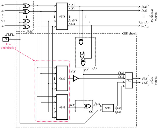
Figure 4.
The structure of the CED circuit organization with the calculations testing based on two diagnostic signs based on the parity code. In Figure: F(X)—diagnosis object, G—generator, G(F)—parity code encoder, G(X)—parity function calculation circuit, Δ(X)—correction function calculation circuit, CC—correction circuit, SDC—self-dual checker, SPSC—signal to pulse sequence converter, TRC—two-rail checker.
The value of the parity function g(X) is formed at the output of block G(F). The signal output from it and additional calculations testing based on parity, coupled with check of the self-duality of the function g(X), make it possible to ensure a complete check of the encoder G(F). There are two subcircuits for calculations testing in the CED circuit. The first one, already described above, is a circuit for calculations testing based on whether the function gδ(X) belongs to the class of self-dual Boolean functions. Its outputs are and . The parity calculations testing subcircuit uses the same encoder G(F), the control logic block G(X) and the inverter. The control logic block G(X) is also an encoder of the parity code and generates the check bit g(X) directly from the values received at the inputs of the diagnostic object. This bit is inverted to check the two-rail of the signal at the outputs of blocks G(F) and g(X). The check outputs of this subcircuit are the outputs and . The check outputs of both check subcircuits are connected to the inputs of a single elementary two-rail checker module (TRC) [22] to obtain a single check output z0(X) and z1(X).
Blocks G(X) and Δ(X) can be implemented together. Which makes it possible to optimize the indicators of structural redundancy of this part of the CED circuit. The output gδ(X) can be a subcircuit of the block G(X) under the best implementation options. In this case, the indicators of the structural redundancy of the CED circuit will differ very slightly from the indicators of the structural redundancy of the CED circuit (by the magnitude of the complexity of the SDC and TRC implementation). It is implemented in accordance with the class structure of the parity check.
The described arrangement of the CED circuit by two diagnostic signs makes it possible to increase the error detection rates at the outputs of the diagnostic object and each CED circuit block. It is clear that in this case, the advantage of the computational testing structure is lost. It is based solely on the self-duality of the transformed parity function. This is because the block diagram Δ(X) can be very simple. However, at the same time, the error detection rate in the diagnostic object’s output can be improved by testing calculations based on two diagnostic signs.
6. Simulation and Experiment
Using the example of an arbitrary combinational device, we will show how the testability characteristics for the device G(F) change. The calculations testing based on two diagnostic signs at once. Let’s define the device by the truth table (Table 1).

Table 1.
Description of the device with the CED circuit for the example in question.
We obtain the values of the functions g(X), gδ(X) and δ(X) on each set of argument values.
The values of g(X) are obtained uniquely by substituting each set of argument values into the formula m = 6. The values of the function δ(X) are determined from the formula. The difficulties consist only in obtaining the values of the function gδ(X) on each set of argument values. There are variants of self-dual functions from four arguments. We could iterate through each of them and use the one that gives the least complex function δ(X), partially or completely coinciding with the function g(X). However, we will not do this here, but use one of the methods for calculating the functions gδ(X). For the second half of the values of the arguments with decimal numbers No. 8–No. 15, that is, for x4 = 1, we define the function gδ(X) = g(X). For the first half of the values of the arguments with decimal numbers No. 0–No. 7 (that is for x4 = 0). We define the values of the function gδ(X) as inverse to the values of the function on the inverse sets of the second half:
Further, the structure shown in Figure 4 is not difficult to synthesize from the data obtained in Table 1.
We obtained a functional description of each of the blocks in the system shown in Figure 4 by performing two-level optimization using the Carnot method [23]. Formulas describing blocks F(X), G(X), and Δ(X) are not given here. We will not evaluate any characteristics other than the testability indicators of block G(F), which has a standard implementation.
Based on the obtained description, we synthesize a structure with calculations testing based on two diagnostic signs. We implement the system model (Figure 5) using Multisim 14.0. In it, the SC1 block is an SPSC block. Block SC2 is the diagnostic object F(X). Block SC3 is the device G(X). Block SC4 is the device Δ(X). Block SC5 is the coder G(F), which is the object of the study. The SC6 and SC7 devices are a self-dual checker and a two-rail signal compression module. The structure of the dual signal tester is shown separately in Figure 6, as it is rarely found in publicly available sources.
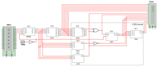
Figure 5.
Experimental CED circuit structure.
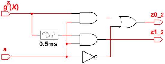
Figure 6.
The structure of the self-dual checker in Multisim 14.0.
The structure of the encoder G(F) is disclosed in Figure 7, where the points A–E are displayed. The authors of the article introduced single stuck-at faults.

Figure 7.
Time diagrams of the structure’s operation with calculations testing based on two signs.
We obtained time diagrams of how the structure in Figure 5 operates with each of the faults. Exhaustive testing was performed by sending the full set of argument values. They are shown in Figure 8, Figure 9, Figure 10, Figure 11 and Figure 12. The effects were applied using the built-in XWG1 code word generator. An XLA1 logic analyzer is installed to monitor the signals at the check points.
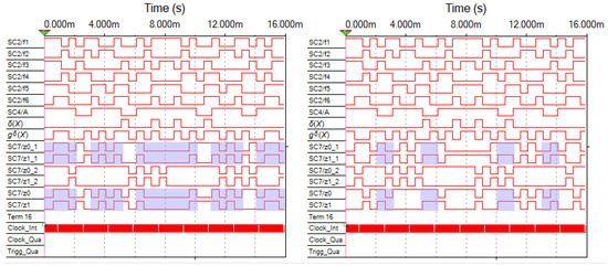
Figure 8.
Time diagrams for faults at the output of the XOR gate at point A.
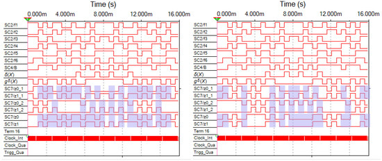
Figure 9.
Time diagrams for faults at the output of the XOR gate at point B.
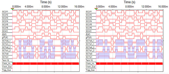
Figure 10.
Time diagrams for faults at the output of the XOR gate at point C.
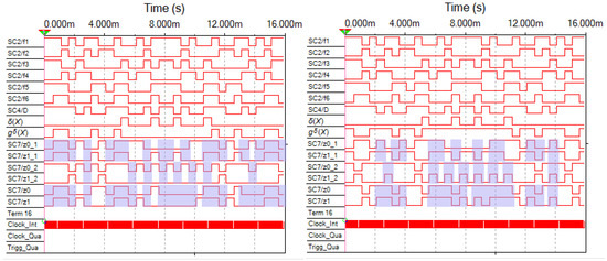
Figure 11.
Time diagrams for faults at the output of the XOR gate at point D.
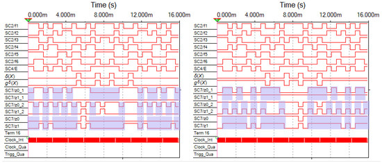
Figure 12.
Time diagrams for faults at the output of the XOR gate at point E.
The structure of the coder G(F) is disclosed in Figure 7, where the points A–E are displayed. The authors of the article introduced single stuck-at faults. Each figure shows a diagram on the left with the stuck-at-0 fault, and on the right with the stuck-at-1 fault. The time diagrams from the testers’ outputs are highlighted. The color shows the clock cycles in which the sets of values of the test arguments are supplied. Outputs z0_1 and z1_1 correspond to the outputs and of the CED circuit shown in Figure 5. At this checkpoint, the parity calculations are checked. Outputs z0_2 and z1_2 correspond to the outputs of the CED circuit shown in Figure 5. At this check point, the self-duality of the signal gδ(X) is checked. Outputs z0 and z1 are the check outputs of the CED circuit by two diagnostic signs.
There are very few test values for coder faults among the sets of argument values when checking the self-duality of the gδ(X) signal. This can be seen in the diagrams. For some of the faults, they do not exist at all due to the peculiarities of the diagnostic object F(X) itself. The testability of the coder is much higher when calculations testing is performed only by parity. The two methods of calculations testing complement each other, as they allow monitoring different diagnostic signs, which increases the performance of the test structure.
Table 2 describes the sets of argument values. They are classified into test and non-test ones. Diagrams showing the proportion of test sets (NT) among those that were submitted to inputs (N) during exhaustive testing are shown in Figure 13. They are used to see the effect of switching to a computational testing method based on two diagnostic signs:
Table 2.
Characterization of sets of argument values.
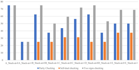
Figure 13.
Diagrams for improving the testability of the encoder G(F).
The testability index was ψ < 40%. The calculations testing was carried out solely on the basis of the self-duality of the gδ(X) signal. This indicator is higher when calculations testing is based on their affiliation to the parity code. In more than half of the discrepancies, ψ < 50%. The indicator for calculations testing based on two diagnostic signs is 60% for more than half of the faults, and 70% for 40% of faults.
A similar trend of increasing testability indicators is observed when considering other diagnostic objects. The check by two diagnostic signs increases the testability indicators for coders in a structure with calculations testing based on self-duality.
7. Discussion
The method of CED circuit synthesis for combinational discrete devices proposed in [16,17,18] is undoubtedly interesting for practical applications. It allows one to significantly reduce the indicators of structural redundancy. Previous studies have shown that at the same time, the values of the indicators of the number of detected faults at the outputs of diagnostic signs decrease slightly. The issues of testability of a compression circuit implemented in the form of a parity coder are not fully discussed anywhere, except for the present work of the authors. However, this is, in principle, a vulnerable place in the CED circuit.
It is possible to increase the testability indicators not only in terms of detecting faults at the outputs of the diagnostic object (which is demonstrated, for example, in [24]). In addition, it is possible to increase the testability of the coder by using additional parity checks. However, this negates the advantages of the approach to using the parity compression circuit itself, which is associated with a potential gain in terms of the complexity of the CED circuit technical implementation. Despite this, a significant effect is created in increasing the testability of the CED circuit.
It is clear that in the best cases it is possible to ensure that the structures of blocks G(X) and Δ(X) do not exceed the complexity of block G(X). This involves the total complexity of the implementation. However, even with a certain excess of this value, the function gδ(X) can also be made quite simple. This follows from the possibilities of obtaining different self-dual functions from t arguments. Therefore, an optimization problem can be solved by choosing the best conversion method that provides the minimum amount of redundancy. The option of fully implementing the parity function could be interesting. It may also be interesting to use a correction function using a single logical expression or with the partial matching of expressions. This will allow you to implement a check circuit with minimal redundancy. The simplest structure will be one in which only one parity function is implemented. Therefore, in practice, the structure proposed by the authors will often be somewhat more complex than the classical parity check structure. However, a slight complication of the CED circuit makes it possible to increase the testability indicators. The diagrams in Figure 13 show that the effect can be up to 20% compared to the testability indicators for only one of the methods. Such indicators are not achieved using classical approaches related to duplication and parity.
The encoder testability theorems can be effectively used in the analysis of testability indicators for structures synthesized by two diagnostic signs using any linear codes. For example, the results of the work can be developed [25]. At the same time, it is also interesting to extend the results obtained to a class of structures with calculations testing based on the self-quasi-duality of Boolean functions. It is also interesting to extend the results to structures with calculations testing based on both the self-duality and self-quasi-duality of calculated functions [20].
The structure with calculations testing by two diagnostic signs operates in the mode of the pulse signal in a pair of combinations due to the signals generated when applying each set of argument values. The results of the work can be effective in testing “delay faults” [26,27]. When forming tests for such faults, it is necessary to use an installation kit. In addition, it is necessary to transmit the fault to the output, which is provided during the pulsed operation of the structure. However, the issues related to fault testing of the “time delay” type errors require separate consideration, because there are various types of malfunctions of this type. Nevertheless, if a “time delay” fault test is implemented, it will immediately include pairs of combinations .
Methods of organizing the CED circuit with calculations testing based on two or more diagnostic signs can be effective in the construction of self-checking discrete devices with respect to various error models.
8. Conclusions
In the course of the research of the authors of this article, it was possible to establish the conditions for ensuring the testability of faults in compression circuits when conducting calculations testing. They are based on the uniqueness of a single function derived from the parity function. It is shown that certain conditions for the testability of the encoder must be met in the implementation described in [16,17,18]. They are not always respected. Calculations testing based on an additional diagnostic sign is an effective way to increase testability indicators. The structure of the CED circuit organization according to two diagnostic signs is proposed in this article. Previously, this structure has not been studied in the scientific literature.
The indicators of the observability of encoder faults can be significantly improved by calculations testing. This is considered from the point of view of parity and from the point of view of self-duality of the calculations testing. The improvement can reach 20% and in some cases even more. This opens up good prospects for the use of CED circuit synthesis methods for two or more diagnostic signs. For example, such methods can be effectively applied in applications where input effects rarely change. This includes, for example, installations for railway signaling and interlocking systems, air defense complexes, control complexes in the nuclear industry, and many others.
An interesting generalization of calculations testing is the testing by groups of outputs with different parity codes [28]. Calculations testing is based on two diagnostic signs, including control by belonging to the parity code and calculations testing of self-duality. In fact, it makes it possible to consider methods for calculations testing based on two or more diagnostic signs using other linear codes. They can be immediately distinguished by codes with a low density of parity checks [29], polynomial codes [30], and many others. If other systematic codes with greater redundancy are used instead of parity codes, the hardware redundancy of the CED circuit will increase. However, at the same time, the error coverage at the outputs of the diagnostic facility will also increase. The specifics of testing encoders as part of systematic code testers will remain. They will be preserved by calculations testing based on two diagnostic signs. The error rates will increase significantly.
In conclusion, it can be stated that the calculations testing based on the parity and self-duality of the check function is an effective method. This method is based on the organization of totally self-checking discrete structures, with high testability of each component.
Author Contributions
Conceptualization, D.V.E.; methodology, D.V.E.; validation, D.V.E.; formal analysis, T.S.P. and D.V.E.; investigation, N.M.A. and D.V.E.; writing—original draft preparation, T.S.P. and D.V.E.; writing—review and editing, D.V.E., A.R.A. and S.T.B.; visualization, E.K.A. and Z.B.T.; supervision, D.V.E.; project administration, E.K.A. and Z.B.T. All authors have read and agreed to the published version of the manuscript.
Funding
This research received no external funding.
Institutional Review Board Statement
Not applicable.
Informed Consent Statement
Not applicable.
Data Availability Statement
Data are contained within the article.
Conflicts of Interest
The authors declare no conflict of interest.
References
- Drozd, O.; Perebeinos, I.; Martynyuk, O.; Zashcholkin, K.; Ivanova, O.; Drozd, M. Hidden Fault Analysis of FPGA Projects for Critical Applications. In Proceedings of the IEEE International Conference on Advanced Trends in Radioelectronics, Telecommunications and Computer Engineering (TCSET), Lviv-Slavsko, Ukraine, 25–29 February 2020; p. 142. [Google Scholar] [CrossRef]
- Chioktour, V.; Kakarountas, A. Adaptive BIST for Concurrent On-Line Testing on Combinational Circuits. Electronics 2022, 19, 3193. [Google Scholar] [CrossRef]
- Soltani, S.; Kouhanjani, M.J. Comparing Three Separate Discrete Algorithms for Generation Maintenance Optimization. In Proceedings of the 8th International Conference on Technology and Energy Management (ICTEM), Babol, Iran, 8–9 February 2023. [Google Scholar] [CrossRef]
- Hahanov, V.; Gharibi, W.; Chumachenko, S.; Litvinova, E. Vector Synthesis of Fault Testing Map for Logic. IAES Int. J. Robot. Autom. (IJRA) 2024, 13, 293–306. [Google Scholar] [CrossRef]
- Mitra, S.; McCluskey, E.J. Which Concurrent Error Detection Scheme to Choose? In Proceedings of the International Test Conference, Atlantic City, NJ, USA, 3–5 October 2000; pp. 985–994. [Google Scholar] [CrossRef]
- Sahana, A.R.; Chiraag, V.; Suresh, G.; Thejaswini, P.; Nandi, S. Application of Error Detection and Correction Techniques to Self-Checking VLSI Systems: An Overview. In Proceedings of the 2023 IEEE Guwahati Subsection Conference (GCON), Guwahati, India, 23–25 June 2023. [Google Scholar] [CrossRef]
- Gavzov, D.V.; Sapozhnikov, V.V.; Sapozhnikov, V.I. Methods for Providing Safety in Discrete Systems. Autom. Remote Control 1994, 55, 1085–1122. [Google Scholar]
- Dobias, R.; Konarski, J.; Kubatova, H. Dependability Evaluation of Real Railway Interlocking Device. In Proceedings of the 2008 11th EUROMICRO Conference on Digital System Design Architectures, Methods and Tools, Parma, Italy, 3–5 September 2008; pp. 228–233. [Google Scholar] [CrossRef]
- Bestemyanov, P.F. Methods of Providing Hardware Safety for Microprocessor Train Control Systems. Russ. Electr. Eng. 2020, 91, 531–536. [Google Scholar] [CrossRef]
- Falkowski, K.; Żokowski, M.; Chodnicki, M.; Mazur, M.; Witoś, M. Self-Diagnostic System for Mini UAV. In Proceedings of the New Trends in Aviation Development (NTAD), Chlumec nad Cidlinou, Czech Republic, 26–27 September 2019. [Google Scholar] [CrossRef]
- Chen, X.; Tong, Z.; Liu, Y.; Wang, Y.; Qing, X. A Hybrid Multimodel-Based Condition Monitoring and Sensor Fault Detection Method for Aero Gas Turbine. IEEE Sens. J. 2024, 24, 32729–32739. [Google Scholar] [CrossRef]
- Sogomonian, E.S.; Slabakov, E.V. Self-Checking Devices and Fault-Tolerant Systems; Radio and Communications: Moscow, Russia, 1989; 208p. (In Russian) [Google Scholar]
- Drozd, A.; Kharchenko, V.; Antoshchuk, S.; Sulima, J.; Drozd, M. Checkability of the Digital Components in Safety-Critical Systems: Problems and Solutions. In Proceedings of the 9th IEEE East-West Design & Test Symposium (EWDTS’2011), Sevastopol, Ukraine, 9–12 September 2011; pp. 411–416. [Google Scholar] [CrossRef]
- Efanov, D.; Sapozhnikov, V.; Sapozhnikov, V.I. Generalized Algorithm of Building Summation Codes for the Tasks of Technical Diagnostics of Discrete Systems. In Proceedings of the 15th IEEE East-West Design & Test Symposium (EWDTS’2017), Novi Sad, Serbia, 29 September–2 October 2017; pp. 365–371. [Google Scholar] [CrossRef]
- Göessel, M.; Ocheretny, V.; Sogomonyan, E.; Marienfeld, D. New Methods of Concurrent Checking, 1st ed.; Springer Science + Business Media B.V.: Dordrecht, The Netherlands, 2008; p. 184. [Google Scholar]
- Saposhnikov, V.; Dmitriev, A.; Goessel, M.; Saposhnikov, V.V. Self-Dual Parity Checking—A New Method for on Line Testing. In Proceedings of the 14th IEEE VLSI Test Symposium, Princeton, NJ, USA, 28 April–1 May 1996; pp. 162–168. [Google Scholar]
- Goessel, M.; Dmitriev, A.V.; Sapozhnikov, V.V.; Sapozhnikov, V. A Functional Fault-Detection Self-Test for Combinational Circuits. Autom. Remote Control 1999, 60, 1653–1663. [Google Scholar]
- Dmitriev, A.; Saposhnikov, V.; Sapozhnikov, V.; Goessel, M.; Moshanin, V.; Morosov, A. New Self-Dual Circuits for Error Detection and Testing. VLSI Des. 2000, 11, 1–21. [Google Scholar] [CrossRef]
- Crama, Y.; Hammer, P.L. Boolean Functions: Theory, Algorithms, and Applications; Cambridge University Press: New York, NY, USA, 2011; p. 687. [Google Scholar]
- Efanov, D.V.; Pivovarov, D.V.; Cortegoso Vissio, N.; Kuptsov, A.O.; Egorov, D.E. Method for Testing Combinational Circuits by Multiple Diagnostic Features Using Weight-Based Sum Codes Properties. Automation 2025, 6, 6. [Google Scholar] [CrossRef]
- Sogomonyan, E.S.; Gössel, M. Design of Self-Testing and On-Line Fault Detection Combinational Circuits with Weakly Independent Outputs. J. Electron. Test. Theory Appl. 1993, 4, 267–281. [Google Scholar] [CrossRef]
- Lala, P.K. Self-Checking and Fault-Tolerant Digital Design; Morgan Kaufmann Publishers: San Francisco, CA, USA, 2001; p. 216. [Google Scholar]
- Zakrevskij, A.; Pottosin, Y.; Cheremisinova, L. Optimization in Boolean Space; TUT Press: Tallinn, Estonia, 2009; p. 241. [Google Scholar]
- Efanov, D.V.; Pogodina, T.S.; Aripov, N.M.; Boltayev, S.T.; Azizov, A.R.; Ametova, E.K.; Shakirova, F.F. Combinational Circuits Testing Based on Hsiao Codes with Self-Dual Check Functions. Computation 2025, 13, 15. [Google Scholar] [CrossRef]
- Efanov, D.V.; Pogodina, T.S. Hamming Codes with Check Bits that are Described by Self-Dual and Self-Quasidual Boolean Functions. In Proceedings of the 20th IEEE East-West Design & Test Symposium (EWDTS’2024), Yerevan, Armenia, 13–17 November 2024; pp. 1–10. [Google Scholar] [CrossRef]
- Higami, Y.; Takahashi, H.; Kobayashi, S.-Y.; Saluja, K.K. Diagnosis of Gate Delay Faults in the Presence of Clock Delay Faults. In Proceedings of the IEEE Computer Society Annual Symposium on VLSI, Tampa, FL, USA, 9–11 July 2014. [Google Scholar] [CrossRef]
- Matrosova, A.Y.; Cherhyshov, S.V.; Kim, O.K.; Nikolaeva, E.A. Constructing a Sequence Detecting Robustly Testable Path Delay Faults in Sequential Circuits. Autom. Remote Control 2021, 82, 1949–1965. [Google Scholar] [CrossRef]
- Goessel, M.; Dmitriev, A.V.; Sapozhnikov, V.V.; Sapozhnikov, V. Detection of Faults in Combinational Circuits by a Self-Dual Test. Autom. Remote Control 2000, 61, 1192–1200. [Google Scholar]
- Amine, T.M.; Ali, D. A New Method for Building Low-Density-Parity-Check Codes. Int. J. Technol. 2019, 10, 953–960. [Google Scholar] [CrossRef]
- Gangopadhyay, D.; Reyhani-Masoleh, A. Multiple-Bit Parity-Based Concurrent Fault Detection Architecture for Parallel CRC Computation. IEEE Trans. Comput. 2016, 65, 2143–2157. [Google Scholar] [CrossRef]
Disclaimer/Publisher’s Note: The statements, opinions and data contained in all publications are solely those of the individual author(s) and contributor(s) and not of MDPI and/or the editor(s). MDPI and/or the editor(s) disclaim responsibility for any injury to people or property resulting from any ideas, methods, instructions or products referred to in the content. |
© 2025 by the authors. Licensee MDPI, Basel, Switzerland. This article is an open access article distributed under the terms and conditions of the Creative Commons Attribution (CC BY) license (https://creativecommons.org/licenses/by/4.0/).