Article

Multiscale Modeling of Mechanical Response of Carbon Nanotube Yarn with Orthotropic Properties Across Hierarchies

by
Aref Mehditabar
1,
Hossein Esfandian
2,* and
Seyed Sadegh Motallebi Hasankola
1
1
Department of Mechanical Engineering, Shomal University, Amol P.O. Box 731, Iran
2
Faculty of Engineering Modern Technology, Amol University of Special Modern Technology, Amol 46158-63111, Iran
*
Author to whom correspondence should be addressed.
Computation 2025, 13(5), 119; https://doi.org/10.3390/computation13050119
Submission received: 10 November 2024 / Revised: 5 December 2024 / Accepted: 26 December 2024 / Published: 14 May 2025
(This article belongs to the Topic Advances in Computational Materials Sciences)

Abstract

This study aims to comprehensively evaluate the mechanical performance of dry-spun twisted carbon nanotube (CNT) yarns (CNTYs) subjected to uniaxial tensile load. To this end, in contrast to earlier approaches, the current research lies in an innovative approach to incorporating the orthotropic properties of all hierarchical structures of a CNTY structure. The proposed bottom-up model ranges from nanoscale bundles to mesoscale fibrillar and, finally, microscale CNTYs. The proposed methodology distinguishes itself by addressing the interplay of constituents across multiple scale levels to compute the transverse properties (orthotropic nature). By doing so, rigidity and mass equivalent principles are adopted to introduce a replacement of the model by converting the truss structure containing two-node beam elements representing (vdW) van der Waals forces in a nanoscale bundle and inclined narrower bundles in mesoscale fibrillar used in previous works to the equivalent shell model. Followed by the evaluation of mechanical properties of nanoscale bundles, they are translated to the mesoscale level to quantify its orthotropic properties and then are fed into the microscale CNTY model. The results indicate that the resultant CNT bundle and fibrillar exhibit much lower transverse elastic modulus compared to those in the axial direction reported in the prior literature. For the sake of validation of the proposed method, the reproduced overall stress–strain curve of CNTYs is compared to that attained experimentally, showing excellent correlation. The presented theoretical approach provides a valuable tool for enhancing the understanding and predictive capabilities related to the mechanical performances of CNTY structures.

1. Introduction

Carbon nanotube (CNT) fibers or yarns (CNTYs) show extraordinarily high mechanical performance and possess tunable electrical properties, endowing great potential application for multifunctional nanocomposites. The optimum distribution of these micro-sized fibers assembled into materials resembling in properties has been a challenging step for the manufacturing industry. Thus, before using them more efficiently on a large scale, it is critical to understand their mechanical behavior spanning over a wide range of magnitudes including nanoscale, mesoscale, and microscale, which can significantly contribute to enhancing the quality of the CNTY. However, translating outstanding properties of constituent CNTs to CNTYs remains elusive and challenging for the widespread applications of these materials, which has partly limited its insertion into real applications. The fundamental reasons for inhibiting their use lie in the confluence of many structural features specifying bulk properties, consisting of those related to the physical and chemical properties, their spatial arraying, and also synergistic weak interactions between adjacent CNTs [1].
On the other hand, difficulties related to the experimental characterization of CNT nanotubes entails developing more efficient multiscale modeling approaches characterizing the hierarchical architecture of CNTYs to scrutinize its mechanical responses. This can serve as a valuable tool for optimum design in their fabrication. More recently, active research dedicated to CNTYs available in diverse engineering applications aims to present a strong strategy for successfully describing their mechanical behaviors contributing to increasing load transferring between their constituents and interface strengthening [2,3,4]. Some open literature in the context of CNTY structural parameters for assessment of upper bounds on their mechanical properties is described next. The axial mechanical responses of CNTs exhibit extraordinarily high tensile strength up to 63 GPa, tensile modulus up to 1.3 TPa, and ultimate fracture strain up to approximately100/0 [5,6,7,8]. The molecular structural mechanics to predict elastic behaviors of MWCNTs was developed by Li and Chou [9]. In their work, CNTs were simulated by a frame-like structure and intra-tube bonding between them van der Waals (vdW forces) modeled by a rod element. Filleter et al. [10] reported a strategy including a numerical model and empirical approach to examine the dominant effects of the CNT–CNT shear interaction within a double-walled nanotube (DWNT) bundle on mechanical responses of CNT-based nanocomposites. Ghavamian et al. [11] applied a finite element (FE) approach jointly with two different types of experiments, i.e., torsional and tensile tests, to determine the shear modulus of single-walled carbon nanotubes (SWCNTs) and MWCNTs. It was concluded that CNTs behave in an anisotropic way, and a tensile test cannot estimate the shear modulus as an independent material property. In another work, elastoplastic properties of CNT wire possessing hierarchical structures of CNTs, CNTYs, and wire were achieved through tensile experiments [12]. Also, the mechanical properties of CNTY fabricated through various techniques were quantified computationally and experimentally through tensile tests [13]. It was demonstrated that enhancing interface shear strength led to increasing yarn strength and changed the failure mechanism from interface sliding to tube rupture. Galiakhmetova et al. [14] characterized the ability of a SWCNT bundle to absorb impact energy subjected to shock loading in a lateral direction.
Mechanical responses of CNTYs composed of bundles made of double-walled nanotubes (DWNTs) were analyzed by Naraghi et al. [15] by using nano-mechanics experiments and multiscale simulations. In this report, the detailed description of interactions between bundles was provided and showed that extending the short polymer chains (oligomers) that are covalently bonded to the surface of CNTs can create stronger shear interfaces between bundles. Moreover, relations between the microstructure of CNTs and their bulk properties toward achieving high strength and toughness based on isotropic material behaviors have been reported by [16]. A theoretical model was presented by Hu et al. [17] to evaluate the torsional mechanical responses of twisted CNT ribbon. Mechanical behaviors of CNT bundles subjected to lateral compression were assessed in plane strain conditions employing the chain model by Abdullina et al. [18]. The impact of different microstructure parameters including the chirality of CNTs, mass density of the bundle, diameter ratio of the constituent CNTs, packing morphologies on torsional and fracture performances of the CNT bundle were explored by Wei et al. [19]. It was indicated that mechanical properties were primarily controlled by the slippage between adjacent CNT nanotubes. Moreover, Park et al. [20] modified the mathematical modeling to capture a combination of straightening and slippage behaviors of the hierarchical structures of CNTYs. In their work, the elastic modulus–strain curves were extracted to estimate the structural response of CNTYs. Moreover, in the case of experimental work, Kim et al. [21] collected stress–strain curves for different dry-spun CNTYs diameters through experimental tensile tests in order to evaluate their axial mechanical properties. However, thus far, it has been noticed that the previous studies of CNTYs are limited to their longitudinal mechanical characterizations across their hierarchal entities, but their transverse behaviors have not been well understood. As such, it is of great interest to develop a comprehensive modeling strategy that accurately assesses their transverse mechanical characterizations throughout their hierarchical structural levels. This is helpful in incorporating their more realistic orthotropic properties in simulating the mechanical response. On the basis of correctly formulated stiffness coefficients using the rigidity equivalent and mass principal approach presented by [22], the hexagonal-like truss structure representing vdW interactions between CNTs in bundles used in the previous studies is transformed to a 2D continuum shell element in FE models at the nanoscale level. The same task is performed to model inclined narrower bundles entangling main longitudinal bundles within fibrillar at the mesoscale level to extract its transverse properties. This procedure facilitates the prediction of stress distribution along the cross-section of CNT bundles and fibrillar through the shear transferred between their nearest constituents under transverse loading conditions. This illuminates routes for creating a more robust model of CNTY components, which is essential to mimic their actual mechanical response and establish integrity throughout its entire structure. The reproduced stress–strain curve of CNTYs using 3D continuum solid elements including shear forces between fibrillars modeled by the contact algorithm capability of ANSYS (https://www.ansys.com/) is found to be properly in line with the average value measured experimentally for a set of fifteen of CNTYs under uniaxial tensile loading. The proposed mathematical model in conjunction with FE models offers an efficient computational tool for determining the mechanical response of CNTY structures.

2. Hierarchy in the Multiscale Model

2.1. Nanoscale Level

2.1.1. Geometric Definition of the CNT Bundle Structure

To obtain a much better mechanical performance of CNTY, scaling up both the strength and robustness of its hierarchical structures comprising the nanoscale CNT bundle and mesoscale fibrillar to macroscopic CNTY is a contributing factor. The CNT bundle materials at the submicron scale preferentially are the most important component in hierarchal structures of the CNTY. The CNT bundle utilized in computational process is assumed to be constructed of an approximately hexagonal unit cell, which is well accepted by the scientific community and supported by both electron energy loss spectroscopy (EELS) and TEMformed bright-field images. A CNT bundle is composed of individual CNTs agglomerated by pure vdW interactions at the molecular level created between adjacent bare ones. The morphology of the bundle with the magnified dashed area in the y-z plane showing vdW interactions between two consecutive CNT nanotubes, which is the most fundamental configuration of a CNT bundle, is demonstrated in Figure 1. This interaction force between CNTs facilitates a continuous CNT web to be drawn from the forest. It should be noted that the actual configuration of a CNT bundle is much more complicated than those demonstrated in Figure 1. It is assumed that in the current study, CNTs are vertically aligned to produce the fully packed bundle indicating robust vdW forces between them.

2.1.2. Mechanical Characterizations of vdW Force Interacting Between Pairs of Aligned CNTs Under Transverse Loading

Based on molecular dynamics concepts, mechanistically, these kinds of covalent interactions within bundles connecting neighboring CNTs describing vdW forces have been replaced by load-bearing beam elements. In the following, a theoretical approach quantifying the mechanical properties of the representative beam element signifying the inter-tube bonding, which can exhibit properties different from those of individual CNT nanotubes, is presented in detail. The elastic strain energy of the representative beam associated with slipping of pairs of neighboring CNTs over each other by bond angle variance γ, as illustrated in Figure 2a,b, is employed for this objective to fully determine the closed-form expression for the elastic modulus of the representative beam describing the vdW interactions. For this purpose, potential energy stored in the equivalent beam representing vdW interactions (Figure 2b), considering two adjacent CNTs under transverse shearing slipping over each other by an amount of γ, is calculated as defined in reference [23].
The aforementioned beam, as shown in Figure 2b, is defined by the height of ζ and square cross-section of W e f f × W e f f , in which W e f f is referred as the effective contact width described as the width within which the empty distance between pairs of nearest-neighboring CNTs given as follows:
W e f f = D o 2 + D o ζ 2
where Do and ζ are outer CNTs’ diameter and the corresponding constraint spacing between adjacent CNTs, respectively. It is worthwhile to mention that according to TEM studies, the minimum distance between interacting CNTs ( ζ ) is considered to be 0.34 ± 0.06 nm, which is very close to that actually measured [10]. Using Hook’s law and expanding Equation (1), the following relation for potential energy is obtained as:
U = 1 2 G γ / ζ 2 W e f f 2 ζ = 1 2 G 1 / ζ W e f f 2 γ 2
where G is the interface shear modulus of our CNTs for interface within the bundle that experimental work suggested is 0.5 TPa [24]. Furthermore, it is well known that the potential energy stored in a Euler–Bernoulli beam with rotationally fixed ends under deformation of γ at the other end, as shown in Figure 2b, is expressed according to the following equation:
U = 1 2 12 E V D W I V D W / ζ 3 γ 2
in which I V D W is the moment of inertia of the cross-section area and E V D W denotes the equivalent elastic modulus of the representative beam. Knowing the formula for the moment of inertia of the rectangular beam, which in our case cross-section has dimensions of W e f f × W e f f , simulating vdW interactions being assumed in the way as in Refs. [25,26] is given by:
I = W e f f W e f f 3 / 12
Substituting Equation (4) into Equation (3) permits us to derive potential energy stored in a beam element in terms of geometrical parameters, elastic modulus, and rotation with respect to end of the beam element as follows:
U = 1 2 E V D W W e f f 4 / ζ 3 γ 2
Finally, combining Equations (2) and (5) and using some algebraic manipulation, the closed-form expression for elastic modulus value of the beam representing vdW within the bundle under transverse loading is extracted as follows:
E V D W = G ζ / W e f f 2
Equation (6) is the key to quantifying the elastic modulus of the representative beam under transverse shearing, relating it to the invariant of the shear modulus of interspace between interacting CNTs and its characteristic bond length and the effective contact width in the 3D space.

2.1.3. Equivalent Shell Representing vdW Forces Between Adjacent CNTs

The structural characteristics and total deformation exhibited by CNT bundles is substantially driven by interfacial contact between CNTs and the nature of vdW forces. On the other hand, approaches to promoting vdW interactions within close-packed bundles using a 1D two-node beam element in the framework of a coarse-grain model falls short under transverse loading, which can introduce defects in the application of required edge boundary conditions. As with CNT bundles with transverse loading condition in the case of plane strain in this study, a plane perpendicular to the axial direction instead of line elements is required to impose the edge boundary/loading conditions. To overcome this deficiency, using a continuum model employing a shell element, as pictured in Figure 3, allows one to provide better description and hampers discontinuity in the force field within the bundle cell. By considering the vdW bond as a continuum element, a structural model of a CNT bundle could benefit from this and increase stress transfer induced through interface shear among adjacent CNTs. The implementation applied to study the mechanical behavior in the transverse direction and simulate interaction between the bundles ensures a perfect transformation from truss configuration into the shell element. Nevertheless, it is indispensable to understand and extract the essential material properties of the representative shell to calibrate the true material properties of a close-packed bundle in the transverse direction, which is of great interest for this study. The continuum method based on the rigidity equivalent concept and mass equivalent principle is applied for this objective to approximate a large truss structure by a continuum model to fully describe the deformation of the CNT bundle in the transverse direction.
At the beginning of the computational procedure, concerning the truss structure to shell element transformation, it is hypothesized that the shell element exhibits isotropic behavior and then its governing equations are introduced and briefly discussed. In this regard, based upon linear elasticity and using Hamilton’s principle, the force resultant–strain relations can be expressed as the following matrix form:
N 1 N 2 S = A 11 A 12 0 A 12 A 22 0 0 0 A 66 ε 1 ε 2 ε 12
In the preceding equation, Nαβ (α, β = 1, 2) are the resultant in-plane forces and S indicates shear force acting on a shell section, Aαβ indicates membrane stiffness coefficients, and εαβ refers to in-plane strains. It is worth mentioning that since the shell is symmetric about the mid-plane, the coupling between extensions and bending is zero. Moreover, Aαβ is defined as:
A 11 = A 22 = E s h s / 1 υ s 2 , A 12 = E s υ s h s / 1 υ s 2 , A 66 = G s h s
where E s ,   υ s ,   h s , and G s separately represent the elastic modulus, Poisson’s ratio, thickness, and shear modulus of the equivalent shell, respectively. By following this construction procedure using the rigidity equivalent principal and mass equivalent principal introduced by reference [22], the stiffness parameters of the equivalent shell of the vdW interactions take the form summarized in Table 1.
It is noteworthy that in Table 1, θ is the orientation angle of the representative beam with respect to the vertical axis as shown in Figure 4.
Additionally, since the density and total mass of the beams in the truss configuration are equal to those of the equivalent shell, i.e., ms = n × (mb) and ρs = ρb, the thickness of the aforementioned equivalent shell is computed as:
t s h e l l = n V s A c r s = n ζ W e f f
in which n is the total number of beams in the truss structure representing vdW forces between neighboring CNT nanotubes within the CNT bundle, and V and Acrs are the volume and cross-section area of the representative beam, respectively.

2.1.4. FE Modeling of CNT Bundle

After finding the required material properties of the equivalent shell representing vdW interactions between CNT nanotubes, ANSYS Programming Design Language having the capability to build a parametric model is employed to model and perform computational procedures. Within the computational approach in this study, the cross-section configuration of each CNT bundle is constructed by individual CNTs vertically aligned modeled as elastic beam elements. Furthermore, the critical steps in the detailed submicron modeling of CNT bundles in the transverse direction is the simulation of interaction between adjacent CNT nanotubes via vdW forces to evaluate the mechanical properties. To find an appropriate approach, the covalent bonds between the neighboring CNT nanotubes, which are responsible for stress transferring occurring due to the shear of the interfaces, are treated as a shell-like structure, which can reflect its mechanical characteristics to build the whole configuration. Furthermore, as mentioned earlier, based on the SEM/TEM images, the minimum spaces between the adjacent CNT nanotubes are postulated to be unchanged and equal to 0.34 nm. In addition, for the CNT bundles under consideration, various CNT diameters fluctuating between 38 nm and 732 nm are examined to depict its significant impacts on transverse properties. We note that the value of interfacial shear modulus between CNT nanotubes denoted by G used in the computational procedure is according to the reported value in reference [24] taken as 0.5 TPa. Also, for analyzing CNT bundles, the outer and inner diameters of each CNT nanotube are considered to be 5 nm and 12 nm, respectively.

2.1.5. Assigned Boundary/Loading Conditions

To explore the mechanical performance of the CNT bundle structure in transverse directions, the following boundary conditions, described in Figure 5, are applied:
Compressive loading is imposed as a pressure in a quasi-static manner in the y-direction at the two opposite top surfaces and angled edges (along the y-axis) of the CNT bundle.
Vertical displacements are constrained (UY = 0) at all the nodes located at the plane of section passing through the midline dividing the area in the y-direction into two equal parts.
The node at the aforementioned plane placed in position with x = 0 is restrained in all directions (UX, UY, UZ = 0) and rotations around all the axes (ROTX, ROTY, ROTZ = 0), as illustrated in Figure 5.
It should be noted that the assigned boundary/loading conditions imposed on the CNT bundle in the x-direction are similar to those described in the y-direction. According to Figure 5, the area between the CNTs shown in purple is the associated equivalent shell representing vdW interactions between CNTs. Also, CNTs modeled as hollow cylinder beam elements in a CNT bundle are shown as lines crossing the circumference of the holes in Figure 5.

2.2. Mesoscale Level

2.2.1. Mechanical Modeling of CNT Fibrillar

The CNT fibrillar from the viewpoint of the hierarchically structured assembly of a CNT, a mesoscale component, is composed of a longitudinal aligned main bundle with inclined narrower bundles (thread/ribbon), as shown in Figure 6b. These inclined thinner bundles (thread) are jammed between the neighboring main bundles, as depicted in Figure 6a–c. Experimental observations show that the narrower bundles are not straightened along the CNT fibrillar axis and have an orientation angle with respect to this axis. According to experimental observations, the level of misalignment of narrower inclined bundles relative to the longitudinal axis varies between 100 and 200 [27]; in this work, 100 is assumed. Since these longitudinal main bundles are randomly packed, CNT fibrillar can form a large number of allotropes and have a complex structure. The main objective of this section is to estimate the mechanical properties of CNT fibrillar in the transverse direction in order to capture a more realistic description of CNT fibrillar behaviors, which, in turn, contributes to enhance the accuracy at the microscale domain. This stage of computational procedure is fundamental since its outputs feed the structural model of CNTY at the highest and last level of the hierarchical structure. According to Figure 6a, fibrillar length is split into n-th segments of the same length indicated with el (effective length), which is a diagonal bundle connecting the two neighboring main bundles with length el end-to-end at opposite sides.
An interesting aspect of the thinner diagonal bundles is that they are stiffer with respect to metal wire with negligible mass, which can be integrated into CNT fibrillars without weakening of the material and also increase the capacity for being stretched. In order to show with more details, the zoomed part of interest selected in Figure 6a is depicted in 2D and 3D dimensions in Figure 6b,c, respectively.

2.2.2. FE Modeling of the CNT Fibrillar

In the FE model of the CNT fibrillar carried out by Pirmoz et al. [26], the two-node structural element with only a translational degree of freedom for its nodes (LINK180) was employed to construct the fibrillar configuration. This element is only suitable for uniaxial compression–tension and no bending develops in the element. Schematic representation of the CNT fibrillar consisting of the main longitudinal bundles connected with some inclined narrower bundles used in reference [26] is shown in Figure 6a.
The strategy forming the basis for modeling the CNT fibrillar of the current research is that in contrast to the previous work [26], the main bundles modeled by only the two-node structural element with only a translational degree of freedom for its nodes (LINK180), SHELL181 are used to simulate the main bundles with diameters of Db (the areas enclosed by purple solid circles shown as a circle in Figure 7). Furthermore, and most importantly for model building, is that instead of a link element with only two-node translations utilized for the thinner diagonal bundles in the previous study [26], the equivalent shell model in our work (the area between the main bundles shown in a gray color in Figure 7) is established. This technique enables one to meet the required loading and edge boundary conditions applied for the present case and facilitates calibration of the orthotropic properties depending on the transverse direction. To this end, since the problem is the plane strain case and involving load only in the plane transverse to the fibrillar, just one of the effective lengths with the length of el in the longitudinal direction from the whole section introduced in Figure 6a is the region of interest to be converted into our considered FE model. The properties and thickness of the equivalent shell of the discrete truss configuration representing inclined thinner bundles can be calculated using the same mathematical procedure as for converting vdW interactions in a CNT bundle. Further details on deriving the continuum equivalence shell are discussed in the previous section. Also, loading and boundary conditions at the edges of the mesoscale model are performed similarly to those of the nanoscale model described previously. At this stage of the computational process, the initial inputs are available and can feed the structural model of CNTY.
In the current study, the cross-sectional structure of CNT fibrillar containing randomly selected 289 main bundles diameters vary from 64 nm to 745 nm, aggregated into a square cross-section at 8.3 µm by 8.3 µm (see Figure 7). Additionally, the distances between neighboring bundles (center-to-center length) are set as the average diameters of existing main bundles within fibrillar used in the analysis. It is worthwhile emphasizing that the diameter of thinner diagonal bundles integrated into the CNT fibrillar is considered to be 38.7 nm. The CNT fibrillar used in finite element (FE) analysis modeled and meshed with the shell 181 element has a four-node element with six degrees of freedom at each node.

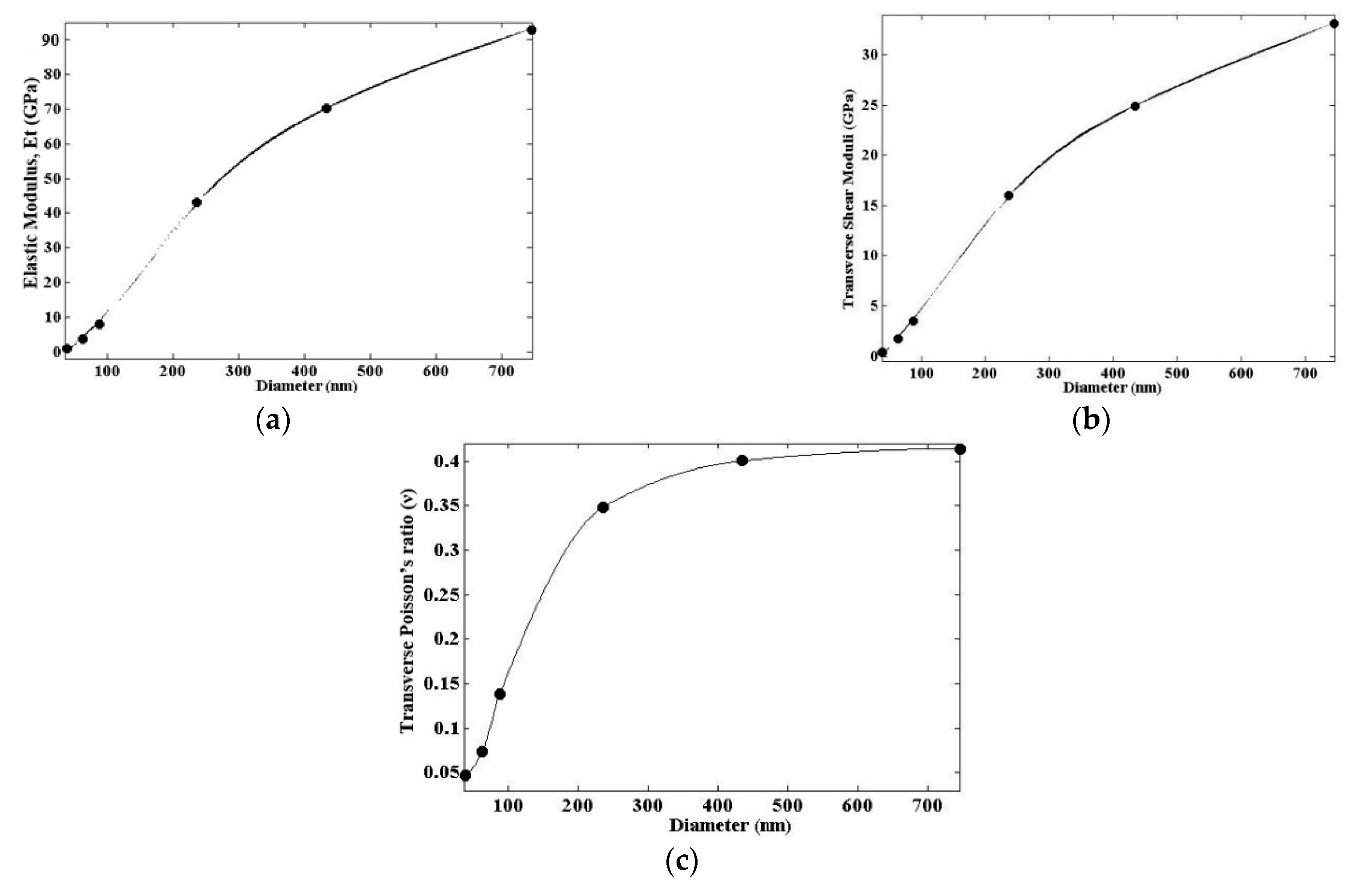
2.3. Microscale Level

2.3.1. General Model to Simulate CNT Yarn

To extract yarn, long strips of CNT fibrillars vertically aligned on a substrate and highly packed are twisted and pulled out together. This twist angle or helix angle (turns of CNTs fibrillars per unit length) has substantial effects on the fabric properties of CNT yarn like mechanical properties due to increasing compactness and contact points between them. In this hierarchical model, CNTY was drawn directly (dry-spun) into a continuous twisted structure composed of individual crimpy fibrillars, which are laterally connected together by capillary forces. The interactions and interface sliding resistance in the contact surface of fiber-to-fiber within the yarn develop frictional forces, which in turn exacerbates the complexity of the framed structural model and significantly increases the overall computational procedure and efforts. To include these parameters effectively, CNT fibrillars in a microscale CNTY structure are treaded as eight-node solid elements (SOLID 185) possessing six degrees of freedom at each node, translations in the nodal x-, y-, and z-directions and rotations about the nodal x, y, and z axes. The envisaged yarn-like CNT has a circular cross-section equally divided by 55 CNT fibrillars having a hexagonal cross-section. Additionally, to capture the interface region between fibrillars, the virtual contact interface elements using node-to-surface contact into the region of interest (at element edges on the contact interface) are inserted in order to transfer the forces between the bonded surfaces. The target is flexible and contact normal is set as ‘normal to target surface’ for all the bonded contact settings. This option included in the contact algorithm capability of ANSYS (APDL) facilitates the ability to model the interaction of the surfaces in contact with each other within CNTY. CONTACT174 and TARGET170 elements are proposed by ANSYS to be overlaid on pair-based contact surfaces in order to define contact and sliding between them.
In the present simulation, contact pairs are constrained with respect to each other so that the penetration of nodes from the contact surfaces to the associated target surfaces is excluded. In APDL, to simulate resistance to sliding, a friction coefficient (µ) of 0.3 is assigned between two surfaces. Figure 8a illustrates the FE model of CNTY with the applied boundary/loading conditions. Also, Figure 8a,b display the cross-sectional view of CNTY with fibrillar arrangement and the schematic illustration of elements employed to represent contact pairs, respectively. As pointed out previously, the present research differs from the foregone works by characterizing the orthotropic nature of CNT bundles and fibrillars and providing further details of the elements and materials. Hence, the reported results in this study could offer a more accurate modeling of the structural behavior of CNT yarn. It is noteworthy to mention that the piecewise elastoplastic stress–strain curve in the axial direction achieved from the mesoscale level is used to extract the axial elastic modulus. The material is assumed to follow the von Mises yield criterion determining the onset of plastic deformation. Furthermore, the isotropic hardening rule introducing the nonlinear trend is employed to dictate the evolution of the yield surface on the deviatoric stress space. Due to complexity in the internal structure of CNTY during deformation governed by straightening and slippage of its components, an appropriate model accurately considering interactions of constituent elements is required.

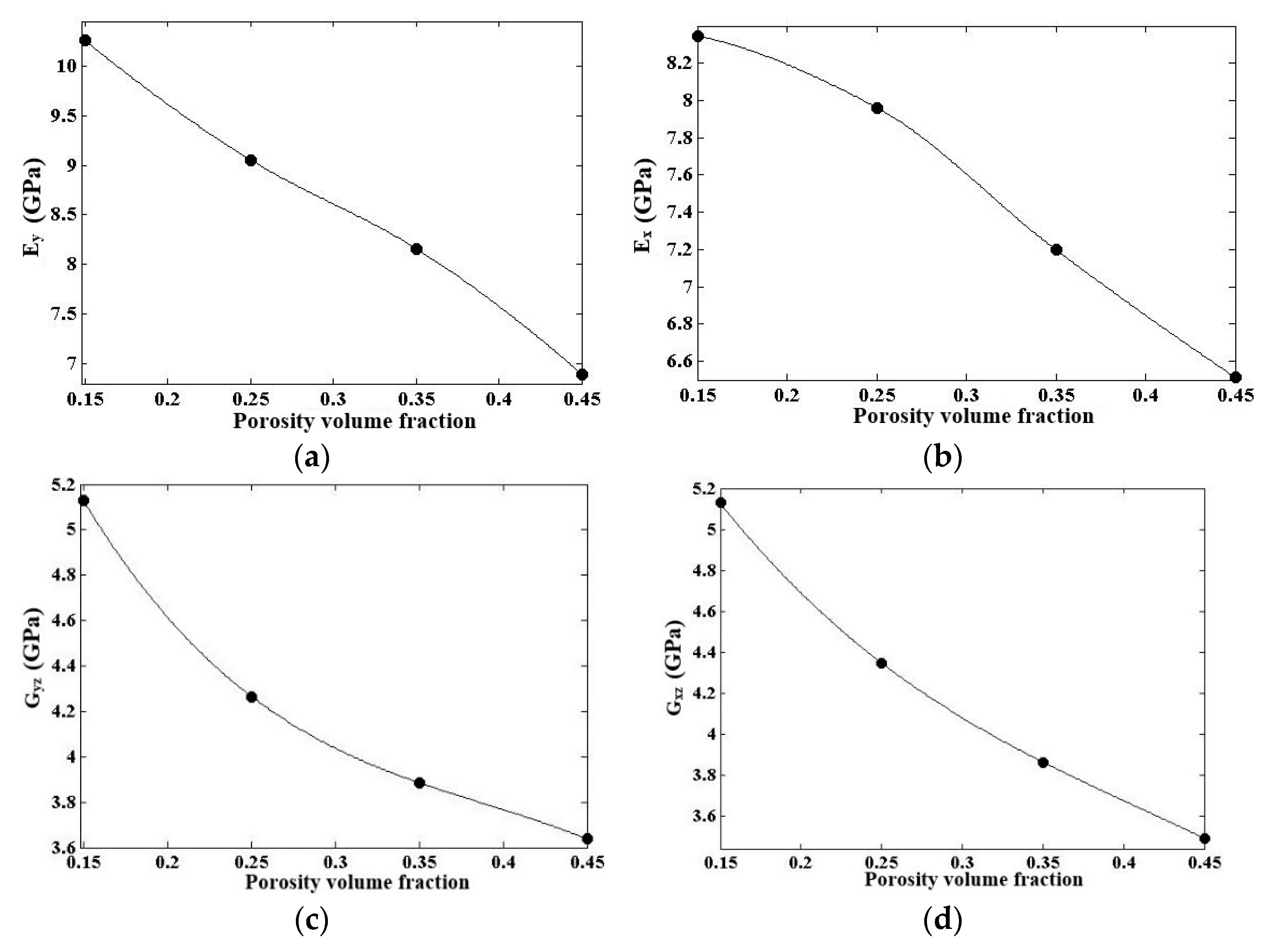
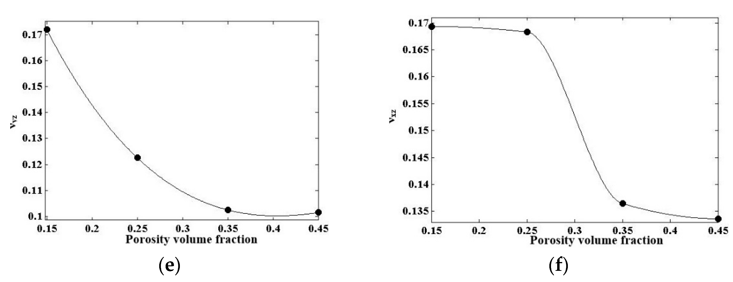
2.3.2. Incorporating Porosities Effects into the CNTY Model

CNTYs render a porous hierarchical network structure having a vital role in mechanical responses of the structure. Porosity within CNTYs causes degradation in their strength by reducing the contact areas at the inter-fibrillars or inter-CNT bundles as the failure process is initiated by the formation of porosity. Collective porosity across yarn hierarchical levels determines the final void content within the CNTY structure. Hence, porosity is an important parameter of CNTYs that must be considered in the modeling. At the microscale level, the obliquity of the fibrillar is the most important parameter in creating gaps between them, causing porosity within the yarn structure. Also, at the lowest hierarchical level, porosity within the CNT bundle is formed as a consequence of misalignment and entanglement between CNTs during web drawing. Thus, using the cross-section area of the CNTY due to porosities is not reliable, and instead a modification factor is adopted to provide a precise estimate of the mechanical response as deformation evolves. The cross-section area modification factor is expressed as:
α = 1 1 β f
in which β f is the ratio of the porosities between neighboring fibrillars to the overall volume of the CNTY ( V c ). To obtain β f , it is necessary to gain insight into the internal porosity, in the three considered levels across the hierarchical structures of the CNTY. Let us start the computational procedure by introducing the formula suggested by Miao et al. [16] for determining the minimum porosity inside a CNT bundle at the lowest level as follows:
ψ b = 1 1 D i / D o 2 / 4 sin π / 3
in which D i and D o denote the inner and outer diameters of the CNTs, respectively. Equation (11) assumes that the CNT bundle is tight and CNTs do not flatten. Based on the SEM observations, the visible voids between individual CNTs are in the size of hundreds of nanometers. Moreover, the volume of cavities present between fibrillars at the microscale level in Equation (10) can be accurately quantified through the applications of the following mathematical equation:
β f = β f f + β f β f β f f
In the present work, in Equation (12), a low-twist CNTY is 80% porous ( β f = 0.8 ) and its fibrillars are 40% porous ( β f f = 0.4 ), and, consequently, Equation (12) achieves β f to be 0.67. By inserting this value in Equation (10), the cross-section area modification factor for the microscale model will be 3.03.

3. Results

3.1. CNT Bundle

For achieving a more precise understanding of the radial deformability of bundle investigated in this research, it is desirable to know the value of the transverse elastic modulus of individual CNTs as inputs in the nanoscale analysis. For this purpose, the value of 30 GPa for the radial elastic modulus of CNT extracted from the experimental procedure reported in [28] is adopted to perform numerical analysis. The transverse elastic modulus, shear modulus, and Poisson’s ratio assessed by this mean for different diameters of the CNT bundle are presented in Figure 9a–c. According to Figure 9a, the transverse elastic modulus of the CNT bundle is greatly enhanced by increasing the bundle diameter with a quadratic relation. This could mean that the radial deformation of the CNT bundle is controlled by the magnitude of its diameter. As the bundle diameter grows from 38.7 up to 88.1, the elastic modulus slightly increases and significantly augments thereafter, approaching a value of 92 GPa. It could be argued that a larger diameter adds a polar moment of inertia and also increases the shear interface between CNTs due to more of them being involved in the deformation, leading to higher mechanical properties. Indeed, the coherence of the CNTs within the bundle and larger contact surface between them are a contributing factor to the elastic modulus of the CNT bundle in comparison to the individual elastic modulus of CNTs. This can help to enhance the load-bearing cross-section of the CNT bundle, and, consequently, significant improvements in mechanical properties are achieved. It is also found that the CNT bundle exhibits a much smaller radial elastic modulus compared to that of the longitudinal elastic modulus reported by Pirmoz et al. [26], which is about 750 GPa.

3.2. CNT Fibrillar

Transverse mechanical properties along principal directions evaluated based on the envisaged model for the CNT fibrillar with a porosity level of 0.45 are summarized in Table 2. As expected in view of the mechanical properties and morphology, it is evident from the results presented in Table 2 that the elastic moduli across the radial directions are substantially lower than that of a previously reported value of 230 GPa in the axial direction by Pirmoz et al. [26]. This is mainly because of sliding neighboring CNT bundles with respect to each other upon the weak interaction and porosities between them, resulting in final separation from the entire fibrillar under transverse shear. This conclusion is further supported by the fact that during inter-bundle slippage, contact areas and subsequently friction forces between components reduce, which is accompanied by a decrease in elastic modulus. Structural characterizations of CNT fibrillar imply that the transverse direction is the weakest one throughout the structure and shearing causing premature failure and significant mechanical properties degradation with much lower external load compared to the axial direction.
To delineate further, the influence of the porosity level on the radial mechanical parameters is investigated in this part. To this end, the mechanical properties of CNT fibrillar with different amounts of porosity volume fractions are shown in Figure 10. This enables a more direct comparison between various cavities’ levels. The mechanical properties of the CNT fibrillar reduce with the increasing porosity. As shown in Figure 10a–d, when the porosity content reaches 0.15, elastic moduli (shear/elastic moduli) corresponding to principal transverse planes are severely degraded, while the content exceeding from this value tends to be stable. Additionally, as can be observed, the variations in transverse elastic moduli exhibit a nonlinear correlation with the porosity content. This fact is attributed to pores’ shape, volume fraction, and location. Also, changes in transverse Poisson’s ratio in the x-z and y-z plane for the envisaged CNT fibrillar are quantified by different porosity levels. It is evident that radial Poisson’s ratios are inversely proportional to the porosity volume fraction. We do observe that CNT fibrillar exhibits a reduction in transverse Poisson’s ratios with increasing porosity content going up to 0.057 and 0.041 in the x-z and y-z planes, respectively, for the extensive porosity. We conclude that the magnitude of porosity content plays a major role in the radial rigidity of a fibrillar.
Actually, it should be emphasized that in mesoscale modeling and simulation, spatially chaotic bundle distributions within the fundamental domain of CNT fibrillars bring about variations in predicting the overall mechanical performance. However, the selected simulation domain and bundle distributions within the structure can reasonably capture the mechanical behaviors of CNT fibrillar in transverse directions.

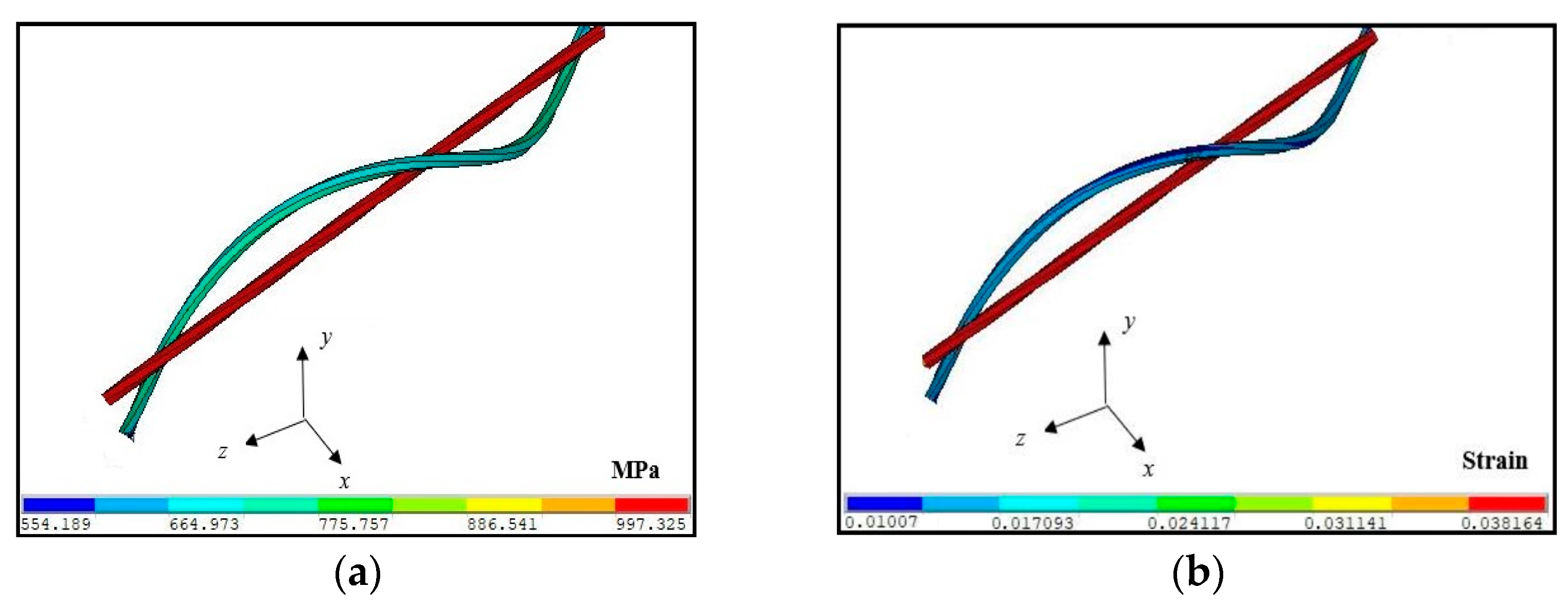
3.3. CNTY in Microscale Structure

Herein, in order to better grasp the mechanical behaviors of CNTY, the details of the fibrillar interactions and deformation mechanism are described. Once CNT fibrillars in CNTY are elongated during deformation, interfacial contact between them begins to increase. In such a case, the transfer of tensile stress to shear stress is enhanced, which causes fibrillar locking. As stress is continuously induced in CNTY under tension, the gripping pressure between fibrillars is built up, resulting in increased inter-tube friction. This phenomenon corroborates the strength of the yarn.

Comparison with Experimental Data

The capability of the proposed multiscale modeling in predicting the mechanical response of CNTY based on the uniaxial tensile loading data obtained from the experiments reported in [29] is evaluated in this section. In experimental procedure [29], a series of uniaxial tensile tests were performed on fifteen CNTY specimens to evaluate the average stress–strain response. The specimens had a gauge length of 40 mm, and the tests were conducted at a loading rate of 0.3 mm/min. These experiments also provided the average values for the lower and upper bounds of the response.
It can be concluded from Figure 11 that the presented methodology modeling for CNTY containing fibrillars with a porosity level of 0.45 reproduces excellent agreement with the experimental results of average value obtained from fourteen specimens. In other words, the overall mechanical behavior of CNTY is reasonably captured by the proposed computational technique. This arises because the incorporated mechanical properties of the constituents across the hierarchical structures of a CNTY exhibiting an orthotropic nature are mostly calibrated well in the present study. According to the average strain–stress curve obtained by experiment, the linear segment is attributed to slippage of the fibrillars due to weak frictional interactions followed by nonlinearity while fibrillars keep slipping. However, the elongation continues until the structural interfaces break down, and finally rupture occurs. This observation also illustrates that the experimental average curve shows an almost negligible elastoplastic transition zone, which is predicted well by the proposed model considering cavities among the fibrillars. Note, however, on comparing the results that the stress–strain curves corresponding to upper bond values attained from the experiment show a more distinctive elastoplastic transition zone with a greater elastic modulus compared with a lower bond curve showing a fairly linear trend until failure initiation. Of note, the magnitude of stress is multiplied by the reduction factor (α) of 3.03 obtained from Equation (10) in order to capture the existing porosities in the CNTY structure.
Figure 12a demonstrates tensile stresses generated in the CNTY yarn for an individual central fibrillar and a circumferential fibrillar. As expected, a central fibrillar is extremely loaded up to a value of almost 1000 MPa, while there is a significant drop in load in fibrillar located in the vicinity of the peripheral region. This finding verifies the fact that the peripheral fibrillar exhibits lower stiffness due to obliquity and inclination of its axis with respect to loading in comparison with a central fibrillar. In general, the contribution of fibrillar strength having an angle with tensile force to yarn strength is reduced in comparison with fibrillars parallel to the testing direction (central fibrillar), leading to degradation in overall yarn strength. To explain this, it is widely known that fibrillars are more capable of carrying a load in their axial tension and show shear-induced failure. The peripheral fibrillars within CNTY are subjected to off-axis loading, resulting in developing shear stress and, as a result, intensifying loading on fibrillar. Moreover, the axial strain field development for an extended central and peripheral fibrillar under uniaxial tensile load is portrayed in Figure 12b. It is clear that, in general, a larger axial strain occurs in straightened central fibrillar compared to fibrillar positioned in the peripheral area. This heterogeneity in the strain field is due to movement restrictions caused by obliquity.

4. Conclusions

In this paper, a novel modeling strategy to accurately predict the mechanical response of CNTY, incorporating the orthotropic properties of its constituents across all hierarchical levels, was presented. At the nanoscale, an analytical solution was developed to model vdW forces and lateral interactions within CNT bundles, providing a detailed representation of transverse mechanical behavior. At the mesoscale, a fibrillar model was constructed to account for the orthotropic properties of longitudinal and inclined bundles under transverse loading. These outputs informed the microscale model, enabling accurate prediction of CNTY mechanical responses. Validation against experimental data from uniaxial tensile tests available in the open literature [26] demonstrated excellent agreement, confirming the model’s accuracy. Compared to prior works, this approach offers advanced nanoscale and mesoscale modeling capabilities, serving as a robust tool for the design and optimization of high-performance CNTY structures.

Author Contributions

Methodology, A.M.; software, A.M.; validation, A.M.; investigation, A.M.; supervision, S.S.M.H.; project administration, H.E. All authors have read and agreed to the published version of the manuscript.

Funding

This research received no external funding.

Data Availability Statement

Due to confidentiality obligations, the data supporting the findings of this study are not publicly available. However, they may be made available by the corresponding author upon reasonable request.

Conflicts of Interest

The authors declare no conflicts of interest.

References

  1. Vilatela, J.J.; Windle, A.H. Yarn-like carbon nanotube fibers. Adv. Mater. 2010, 22, 4959–4963. [Google Scholar] [CrossRef] [PubMed]
  2. Cumings, J.; Zettl, A. Low-friction nanoscale linear bearing realized from multiwall carbon nanotubes. Science 2000, 289, 602–604. [Google Scholar] [CrossRef] [PubMed]
  3. Paci, J.T.; Furmanchuk, A.O.; Espinosa, H.D.; Schatz, G.C. Shear and friction between carbon nanotubes in bundles and yarns. Nano Lett. 2014, 14, 6138–6147. [Google Scholar] [CrossRef] [PubMed]
  4. Vilatela, J.J.; Elliott, J.A.; Windle, A.H. A model for the strength of yarn-like carbon nanotube fibers. ACS Nano 2011, 5, 1921–1927. [Google Scholar] [CrossRef]
  5. Samsonidze, G.G.; Samsonidze, G.G.; Yakobson, B.I. Kinetic theory of symmetry-dependent strength in carbon nanotubes. Phys. Rev. Lett. 2002, 88, 065501. [Google Scholar] [CrossRef]
  6. Shenderova, O.; Zhirnov, V.; Brenner, D. Carbon nanostructures. Crit. Rev. Solid State Mater. Sci. 2002, 27, 227–356. [Google Scholar] [CrossRef]
  7. Yu, M.-F. Fundamental mechanical properties of carbon nanotubes: Current understanding and the related experimental studies. J. Eng. Mater. Technol. 2004, 126, 271–278. [Google Scholar] [CrossRef]
  8. Yu, M.-F.; Lourie, O.; Dyer, M.J.; Moloni, K.; Kelly, T.F.; Ruoff, R.S. Strength and breaking mechanism of multiwalled carbon nanotubes under tensile load. Science 2000, 287, 637–640. [Google Scholar] [CrossRef]
  9. Li, C.; Chou, T.-W. Elastic moduli of multi-walled carbon nanotubes and the effect of van der Waals forces. Compos. Sci. Technol. 2003, 63, 1517–1524. [Google Scholar] [CrossRef]
  10. Filleter, T.; Yockel, S.; Naraghi, M.; Paci, J.T.; Compton, O.C.; Mayes, M.L.; Nguyen, S.T.; Schatz, G.C.; Espinosa, H.D. Experimental-computational study of shear interactions within double-walled carbon nanotube bundles. Nano Lett. 2012, 12, 732–742. [Google Scholar] [CrossRef]
  11. Ghavamian, A.; Rahmandoust, M.; Öchsner, A. On the determination of the shear modulus of carbon nanotubes. Compos. Part B Eng. 2013, 44, 52–59. [Google Scholar] [CrossRef]
  12. Li, D.; Yang, Q.-S.; Liu, X.; Shang, J.-J. Experimental investigation on tensile properties of carbon nanotube wires. Mech. Mater. 2017, 105, 42–48. [Google Scholar] [CrossRef]
  13. Beese, A.M.; Wei, X.; Sarkar, S.; Ramachandramoorthy, R.; Roenbeck, M.R.; Moravsky, A.; Ford, M.; Yavari, F.; Keane, D.T.; Loutfy, R.O. Key factors limiting carbon nanotube yarn strength: Exploring processing-structure-property relationships. ACS Nano 2014, 8, 11454–11466. [Google Scholar] [CrossRef]
  14. Galiakhmetova, L.K.; Bachurin, D.; Korznikova, E.; Bayazitov, A.; Kudreyko, A.; Dmitriev, S. Shock loading of carbon nanotube bundle. Mech. Mater. 2022, 174, 104460. [Google Scholar] [CrossRef]
  15. Naraghi, M.; Bratzel, G.H.; Filleter, T.; An, Z.; Wei, X.; Nguyen, S.T.; Buehler, M.J.; Espinosa, H.D. Atomistic investigation of load transfer between DWNT bundles “crosslinked” by PMMA oligomers. Adv. Funct. Mater. 2013, 23, 1883–1892. [Google Scholar] [CrossRef]
  16. Miao, M.; McDonnell, J.; Vuckovic, L.; Hawkins, S.C. Poisson’s ratio and porosity of carbon nanotube dry-spun yarns. Carbon 2010, 48, 2802–2811. [Google Scholar] [CrossRef]
  17. Hu, X.; Zheng, Y.; Sun, G.; Wang, P. Understanding the torsional mechanical behavior of twisting carbon nanotube ribbon with different boundary conditions. Mech. Mater. 2024, 190, 104906. [Google Scholar] [CrossRef]
  18. Abdullina, D.U.; Korznikova, E.A.; Dubinko, V.I.; Laptev, D.V.; Kudreyko, A.A.; Soboleva, E.G.; Dmitriev, S.V.; Zhou, K. Mechanical response of carbon nanotube bundle to lateral compression. Computation 2020, 8, 27. [Google Scholar] [CrossRef]
  19. Wei, H.; Ting, H.Z.J.; Gong, Y.; Lü, C.; Glukhova, O.E.; Zhan, H. Torsional Properties of Bundles with Randomly Packed Carbon Nanotubes. Nanomaterials 2022, 12, 760. [Google Scholar] [CrossRef]
  20. Park, J.; Lee, J.; Lee, D.-M.; Lee, S.-H.; Jeong, H.S.; Lee, K.-H.; Kim, S.M. Mathematical model for the dynamic mechanical behavior of carbon nanotube yarn in analogy with hierarchically structured bio-materials. Carbon 2019, 152, 151–158. [Google Scholar] [CrossRef]
  21. Kim, J.-G.; Suh, D.; Kang, H. Large variation in Young’s modulus of carbon nanotube yarns with different diameters. Curr. Appl. Phys. 2021, 21, 96–100. [Google Scholar] [CrossRef]
  22. Zhang, W.; Xi, A.; Siriguleng, B.; Liu, G. An equivalent cylindrical shell model of vibration analysis based on simplified repeating unit cell for ring truss structure. J. Sound Vib. 2019, 459, 114847. [Google Scholar] [CrossRef]
  23. Johnston, E.R.J.; DeWolf, J.T.; Beer, F.P. Mechanics of Materials; McGraw-Hill: New York, NY, USA, 2001. [Google Scholar]
  24. Lu, J.P. Elastic properties of carbon nanotubes and nanoropes. Phys. Rev. Lett. 1997, 79, 1297. [Google Scholar] [CrossRef]
  25. Li, H.; Guo, W. Transversely isotropic elastic properties of single-walled carbon nanotubes by a rectangular beam model for the C-C bonds. J. Appl. Phys. 2008, 103, 103501. [Google Scholar] [CrossRef]
  26. Pirmoz, A.; Abot, J.; Avilés, F. Simulation of mechanical response of carbon nanotube yarns under uniaxial tensile loading. Mech. Mater. 2022, 165, 104144. [Google Scholar] [CrossRef]
  27. Lekawa-Raus, A.; Koziol, K.K.; Windle, A.H. Piezoresistive effect in carbon nanotube fibers. ACS Nano 2014, 8, 11214–11224. [Google Scholar] [CrossRef]
  28. Palaci, I.; Fedrigo, S.; Brune, H.; Klinke, C.; Chen, M.; Riedo, E. Radial elasticity of multiwalled carbon nanotubes. Phys. Rev. Lett. 2005, 94, 175502. [Google Scholar] [CrossRef]
  29. Anike, J.C. Carbon Nanotube Yarns: Tailoring Their Piezoresistive Response Towards Sensing Applications. Ph.D. Thesis, Harvard University, Cambridge, MA, USA, 2018. [Google Scholar]
Figure 1. Hexagonally close-packed bundle including vdW interactions between adjacent CNTs holding them together with magnified lateral view.
Computation 13 00119 g001
Figure 2. (a) Schematic of pairs of CNTs and their interactions; (b) equivalent beam element simulating vdW force.
Computation 13 00119 g002
Figure 3. The model of equivalent shell of the deployed truss structure representing vdW interaction within CNT bundle: (a) Hexahedral truss model for van der Waals interactions between CNT nanotubes; (b) Equivalent hexahedral shell.
Computation 13 00119 g003
Figure 4. The global coordinate system and orientation angle of the representative beam with respect to y-direction.
Computation 13 00119 g004
Figure 5. Schematic of the prescribed edge boundary conditions and loading applied on the resultant CNT bundle containing 37 CNTs.
Computation 13 00119 g005
Figure 6. (a) Global view of the studied CNT fibrillar composed of longitudinal main bundles and diagonal bundles; (b) 2D view of the zoomed-out part within the fibrillar configuration; (c) 3D view of the zoomed-out part within the fibrillar configuration.
Computation 13 00119 g006
Figure 7. Schematic layout for cross-section in mesoscale (fibrillar) model with porosity level of 0.45 porosities including 289 longitudinal main bundle (shown as a circle) and the spaces occupied between them illustrated by gray color representing inclined narrower bundles modeled by shell element.
Computation 13 00119 g007
Figure 8. (a) Simulation of idealized CNTY composed of fibrillars considered as a three-dimensional SOLID element as a component within CNTY model; (b) the cross-sectional view idealized yarn model; (c) configuration schematic representation of the contact elements used for contact pairs between neighboring fibrillars.
Computation 13 00119 g008
Figure 9. Variation of transverse elastic properties versus bundle diameter: (a) elastic modulus, (b) shear modulus, (c) Poisson’s ratio.
Computation 13 00119 g009
Figure 10. Elastic properties as a function of porosity: (a) elastic modulus in the y-direction, (b) elastic modulus in the x-direction, (c) shear modulus in the y-z plane, (d) shear modulus in the x-z plane, (e) Poisson’s ratio in the y-z plane, (f) Poisson’s ratio in the x-z plane.
Computation 13 00119 g010aComputation 13 00119 g010b
Figure 11. Comparison of the experimental stress–strain responses of the CNTY samples under uniaxial tensile loading and the proposed multiscale model.
Computation 13 00119 g011
Figure 12. (a) Comparison of axial stress in z-direction induced in a central and circumferential fibrillar within CNTY omitting the reduction factor of 3.03 to include cavities effect; (b) Comparison of axial strain in z-direction for a central and circumferential fibrillar within the CNTY.
Computation 13 00119 g012
Table 1. Equivalent stiffness coefficients used for the equivalent shell of vdW interactions [22].
Membrane Stiffness
A 11 = i = 1 n r i cos 4 ( θ ) A 12 = i = 1 n r i cos 2 ( θ ) sin 2 ( θ )
A 22 = i = 1 n r i sin 4 ( θ ) A 66 = i = 1 n r i cos 2 ( θ ) sin 2 ( θ )
where r i = 1 : n = E V D W A V D W / ζ ,   m i = 1 : n = E V D W I V D W / ζ
Table 2. Computed transverse mechanical properties of individual CNT fibrillar with porosity level of 0.45.
Elastic Moduli (GPa)Shear Moduli (GPa)Poisson’s Ratios
EyExGyxGxzνyzνxz
6.8986.5143.6373.4900.1450.134
Disclaimer/Publisher’s Note: The statements, opinions and data contained in all publications are solely those of the individual author(s) and contributor(s) and not of MDPI and/or the editor(s). MDPI and/or the editor(s) disclaim responsibility for any injury to people or property resulting from any ideas, methods, instructions or products referred to in the content.

