Abstract
Nowadays, a prime technology in generation IV nuclear reactors, the supercritical water reactor (SCWR), is the main object of focus. The current article aims to develop a thermal hydraulic numerical model for predicting density wave oscillation (DWO) in a supercritical water natural circulation loop (SCWNCL). A one-dimensional thermal hydraulic mathematical model was developed. The numerical model consists of nonlinear mass, momentum, and energy conservation equations, which were discretized by applying the implicit finite difference technique. The numerical model was validated with experimental results, and numerical simulations were carried out to find the marginal stability boundary (MSB) and draw the stability map for the loop. Further, the effects of geometry (i.e., diameter and hot leg length) and operating parameters (i.e., inlet system pressure and friction factor) on the density wave oscillation of the SCWNCL were analyzed.
1. Introduction
A natural circulation loop (NCL) is a passive safety device used to transfer heat from a heat source to the sink due to fluid flow in the system. This fluid flow occurs in the system due to density differences caused by the volumetric expansion of the coolant [1,2]. Due to its potential properties, such as simple construction, compact size, absence of moving parts and low cost, NCL is used in various applications, namely electronic device cooling [3], solar heater [4], geothermal power generation [5], and nuclear reactor [6]. Day by day, demand for high energy increases environmental pollution. Many scientists are working in their particular area of research to increase the efficiency of plants and reduce environmental pollution using certain eco-friendly working fluids. Supercritical water (SCW) is one of the most popular working fluids used in many applications to remove heat from the systems. Due to the unique thermophysical properties of SCW, it is used as a working fluid in a nuclear reactor [7,8]. For example, the thermal efficiency of the SCW used in nuclear power plants (SCWRs) is close to 44–45%, which is higher than the thermal efficiency of 30–32% of the boiling water reactor (BWR) [9,10,11,12,13,14]. In the SCWRs, the size of the turbine is compact due to high steam enthalpy and specific heat capacity, which reduces the capital cost of the load [15]. Hence, it will be very helpful for nuclear power plants (NPPs) to combine these advantages. However, the interaction between driving gravitational and resistive frictional forces may cause instability of the loop due to the system’s self-correcting nature, which is a severe problem for NPPs. At the pseudocritical point, a supercritical fluid undergoes severe changes in all thermophysical characteristics, resulting in extreme changes in the intensity of forces and the related feedback effect [16]. In the last decade, many researchers have investigated various aspects of SCNCL, and the majority of them have focused on stability assessment.
The first analytical model of SCNCL was developed by Chatoorgoon et al. in 2001 [17], for a rectangular open SCNCL with a horizontal heater and horizontal cooler (HHHC) by considering both points and distributed heat sources on the heater and cooler section. In the steady state, the mass flow rate of the loop increased with reactor power and reached a maximum. Thereafter, the mass flow rate decreased with an increase in the reactor power and the maximum steady-state mass flow rate was used as the marginal stability criterion for the loop. Several operating and geometry parameters were analyzed in the further study by Chatoorgoon et al. in 2005 [18,19] for three different working fluids, namely carbon dioxide (CO2), water, and hydrogen. It was observed that the stability behavior of CO2 was quite similar to that of SCW, and marginal stability came under 95% of the maximum steady-state mass flow rate trend. On the other hand, in 2008, Jain et al. [20] reported that the nonlinear stability analysis outcomes were not similar to the previous conclusion of Chatoorgoon using constant pressure drop boundary conditions. In the study of Chatoorgoon et al. [19], the discrepancy was found related to the undesired dissipative and dispersive effects caused by the use of a long temporal step. Vijayan et al. in 2010 [21] developed a simple 1-dimensional (1-D) mathematical model to estimate the steady-state characteristics of the loop for three different phases i.e., single phase, two phase, and supercritical phase (SCP). It was observed that the mass flow rate of SCP was similar to the two phase, whereas the stability characteristic was different from the single phase [21,22]. In 2010, M. Sharma et al. [23,24] developed both linear and nonlinear numerical models to predict the instability of SCNCL and reported that steady-state mass flow rates at various powers were in good agreement with the experimental results. A marginal stability point (MSP) was observed at 7.53 kW and 8 MPa, but not experimentally. This discrimination come into existence due to the nonconsideration of the heating structure in their simulation model. They have presented the effect of diameter on linear stability. It was observed that the unstable zone increased with an increase in diameter. According to Chen et al. [25], numerical modeling of supercritical CO2 revealed a shift from unstable repetitive–reversal flow to stable one-directional flow at a crucial heat source temperature near the pseudocritical temperature. Abhilash et al. in 2015 [26], reported the dynamic response of the SCNCL using power upsurge or downsurge. Power upsurge increases initial instability in the system, characterized by more significant amplitude variations. Krishnani et al. in 2017 [27], reported a 3-D simulation model to predict the effect of inclination angle on the stability of SCNCL using CO2 as a working fluid. Unstable oscillations diminished dramatically as inclination increased, owing to a reduction in gravity acceleration and turn local buoyant force by a factor of the cosine of inclination angle. Goudarzi et al. in 2018 [28], reported a heat transfer method for different arrangements of the heater and cooler in single-phase NCL by applying entransy, and it was found that no instability occurs in the vertical heater and vertical cooler NCL. Deng et al. in 2019 [29], conducted a computational and experimental investigation on the flow transition aspects of SCNCL using CO2 as a working fluid, and it was discovered that the flow in NCL was highly responsive due to fluctuations of heat influx. In 2021, Wahid et al. [30] developed a 3-D computational model of SCNCL using CO2 as a working fluid in the ANSYS (CFD) to predict flow instability, and at a particular heat power, marginal stability was observed. Besides this, increased hot pockets of temperature caused increased instability in the loop.
Ambrosini et al. in 2008 [16], repotted the stability analysis of heated channels using the dimensionless numbers at supercritical pressure. The dimensionless parameters were designed based on the conventional phase change and subcooling numbers used in the case of boiling channels, and a unique formulation was proposed that makes use of fluid characteristics at the pseudocritical (PC) temperature as a function of pressure. Dutta et al. in 2015 [31], also studied the DWI of the CANDU SCWR using dimensionless numbers, i.e., pseudo-subcooling number (Npsub) and pseudo-phase change number (Nppch), and obtained the marginal boundary of stability for the reactor. It was observed that with an increase in the mass flow rate, the stable zone increases.
One of the most critical concerns is minimizing instability and increasing the thermal efficiency of the loop without compromising its performance. As a result, in NCLs, the possibility of instabilities of a disorder and uncertain behavior must be diminished for loop design. Hence, the primary aim of the present work is to validate the current model with experimental data, investigate the possible occurrence of density wave instability (DWI), and identify the marginal stability boundary for the SCWNCL to bifurcate stable and unstable regimes. Moreover, the effect of various operating (i.e., inlet system pressure and friction factor) and geometry (i.e., diameter and hot leg height) parameters on the DWI in the loop is investigated to determine possible causes of instability. The present outcomes may help other researchers to critically choose the geometry and operating parameters that enhance the efficiency of the SCWNCL.
2. Detailed Description of the Loop
The schematic diagram of the horizontal heater and horizontal cooler (HHHC) SCWNCL is shown in Figure 1, and all of the loop elements and operating information are included in Table 1.
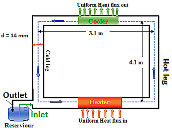
Figure 1.
Schematic diagram of HHHC SCWNCL.

Table 1.
Details of all the parts and operating systems of the SCWNCL [32].
The boundary conditions, as well as the initial conditions, influence the solution of balancing coupled equations, and the steady-state solution is used as an initial condition for transient conservation equations. For the steady-state and transient investigations, the applied boundary conditions at the inlet and outlet are known as constant pressure and inlet-specific enthalpy. The inlet and exit of the loop are linked in the huge tank to ensure zero pressure drops in the loop, and inlet pressure and inlet-specific enthalpy are kept constant.
3. Mathematical Model
The current mathematical model is a one-dimensional nonlinear linked balance mass, momentum, and energy equation whose flow direction characteristics can vary. Numerical solutions are used to solve these balancing equations [31,33,34].
where
All the transient terms consist in .
All the convection terms consist in .
All the source terms consist in .
- Equation of state
- Determination of friction factor
The relationship between friction factor (f) and nondimensional Reynolds number (Re) is presented below to compute the friction factor for laminar and turbulent flow in the loop to avoid discontinuity. The actual Reynolds number is compared to the calculated value to determine if the flow is laminar or turbulent, and the friction factor for each node is then calculated.
3.1. Steady State Numerical Technique
The temporal terms are first removed, and the spatial terms are then discretized using the finite difference approach in the governing differential (GD) balance coupled nonlinear Equation (1). The discretized equations [31,33,34] are shown below:
3.2. Transient Numerical Technique
For solving the transient governing equations, Equation (1) was initially converted into a primitive form, as shown in Equation (8):
where =, is the function of , and D is the source vector.
The characteristics of Equation (8) depend on the eigenvalues of the matrix . The eigenvalues are found to be real and distinct, and Equation (8) is identified as hyperbolic. Further, Equation (8) is modified in a characteristic form, as given in Equation (9).
where is a diagonal element of eigenvalues of the matrix .
The governing Equation (9) is discretized by using the finite difference technique. The discretized equations are given below. All the sets of equations consist of spatial and temporal terms, the spatial derivative terms of the first two equations are discretized by backward difference, and the third equation is discretized by forward difference technique. All discretized equations are combined by applying boundary conditions (BC) and solved up to the convergence value [31,33,34].
3.3. Validation of Results
The potential of the present code to simulate the behavior of SCNCL has already been validated with numerical code SPORT [17], SUCLIN [35], and NOLSTA [36] by Rai et al. [37]. Further, the results obtained from present numerical mathematical model have been compared with the experimental results for the HHHC loop reported by Sharma et al. [38]. The key operating parameters used in their study includes diameter of the loop (13.88 mm), riser height (4.1 m), inlet temperature (350 °C), inlet and exit pressures (24.10 MPa), and a consistent zero pressure drop in the loop. Water is used as a working fluid in the loop. The variation of the mass flow rate with respect to the heater power gives a similar pattern, which is qualitatively identical to the experimental results. However, there is a slight deviation in magnitude due to the friction factor and loss of coefficient at the inlet and outlet. It has been observed in Figure 2 that the deviations in mass flow rate from the experimental results are very small. Moreover, the maximum positive deviation in the current model is 9.40% and the minimum (negative deviation) is 9.50%, which is acceptable.
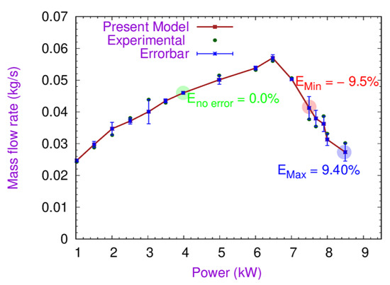
Figure 2.
Validation of the present model with experimental results.
3.4. Time Grid Independence Test
The accuracy of the transient instability prediction for SCNCL mainly depends on the selection of “step size of time”. Hence, it is vital to select an accurate step size of time, otherwise the prediction of instability may give absurd outcomes. For time step independent analysis, numerical simulations have been performed using three different grid sizes of time 0.001, 0.002, and 0.005 s, keeping identical operating and geometry parameters for all three cases. The operating and geometry parameters for these simulations include supplied heater power (0.020 MW), operating pressure (25.00 MPa), loop diameter (14 mm), and riser height (4.1 m). From Figure 3, it is observed that the mass flow rate with respect to time for the step size of time 0.001 and 0.002 s overlap with each other, whereas the grid size of time 0.005 s shows a slight deviation from the other two time steps. To optimize the simulation time and correctly predict instability in the loop, the 0.001 s time step was used in the simulation.
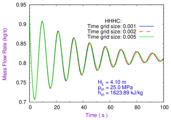
Figure 3.
Fluctuation of mass flow rate with respect to time for three different time steps.
4. Results and Discussions
The DWI of the SCWNCL was explored. The influence of geometry and operational factors on the DWI of the SCWNCL was also investigated.
4.1. Density Wave Instability
The von Neumann stability criteria were used to calculate the density wave instability. The amplitude of mass flow rate has been calculated with respect to time for a certain input, such as supplied heater power, inlet pressure, and inlet-specific enthalpy. The SCWNCL stability is demonstrated by the ratio of the mass flow rate of the current time step to that of the preceding time step. The requirement for stability is listed below:
where G is the stability criteria coefficient, is the new time step mass flow, and is the previous time step mass flow.
The criterion of DWI is given in Equation (13). This method has already been used by Rai et al. [37] to demonstrate the transient instability mechanism in the loop.
The numerical simulation was conducted to determine the state of the system in terms of unstable, marginal stable, and stable points for three distinct applied reactor powers of 26.0, 26.0, and 21 kW at 1623.89 kJ/kg inlet-specific enthalpy and 25 MPa inlet system pressure. The geometrical parameters, such as diameter (14 mm) and riser height (4.1 m), were constant across all the simulations. From Figure 4a, it can be seen that the mass flow rate increases with the increase in time at heater power 26.0 kW. In addition, the amplitude oscillation of mass flow ratio for subsequent time step is greater than one, which shows the occurrence of DWI in the loop and therefore an unstable system. The results, shown in Figure 4b, show that the amplitude oscillation of mass flow ratio is less than one at 21.0 kW heater power, which represents a stable system. From Figure 4c, it can be observed that the amplitude oscillation of mass flow rate neither increases nor decreases with the increase in time at heater power 24.08 kW, and its mass flow rate amplitude ratio is equal to one, which represents a marginal stable system. Further, simulations were performed to find all marginal stable points (MSPs) and obtain the stability map for the SCWNCL by connecting the MPSs.
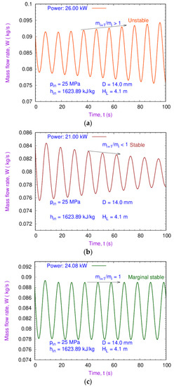
Figure 4.
Density wave instability phenomena of the loop: (a) unstable, (b) stable, and (c) marginal stability.
4.2. Effect of Loop Diameter
The DWI is strongly dependent on loop diameter. The mass flow rate is higher at larger diameters [24]. Simulations have been performed at 14 and 18 mm while keeping other parameters constant, such as inlet-specific enthalpy of 1623.89 kJ/kg, inlet system pressure of 25.0 MPa, riser height of 4.1 m, and heater power of 0.020 kW. The outcomes of the simulation were compared, and it is observed that the mass flow rate increases with an increase in diameter, as shown in Figure 5. The results in Figure 5 also demonstrate that the amplitude oscillation of mass flow rate decreases with an increase in diameter with respect to time, which shows that the flow stability increases with an increase in diameter. Further various simulations have been carried out at three different diameters, e.g., 14, 16, and 18 mm, keeping a constant inlet system pressure of 25.0 MPa and riser height of 4.1 m. The outcomes show the marginal stability boundary (MSB) and bifurcate the unstable and stable zone. It is observed that the stable zone increases with an increase in diameter, as shown in Figure 6.
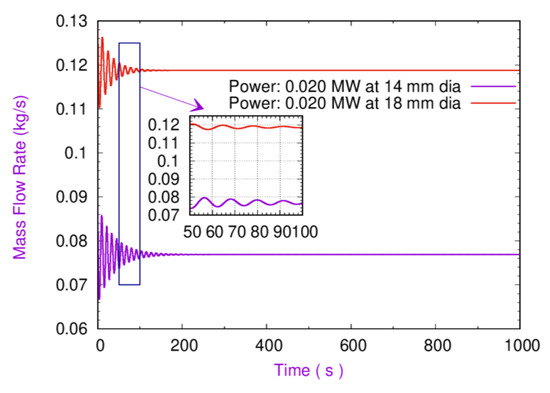
Figure 5.
Variation of mass flow rate vs. time.
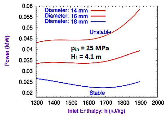
Figure 6.
Effect of diameter on the DWI of the loop [37].
Again, two different loop diameters (i.e., 16 and 18 mm) were chosen to compare the effect of the loop diameters on the MSBs of DWIs using the dimensionless numbers Nppch and Npsub, and the results are shown in Figure 7. The results demonstrate a monotonic enhancement of the MSB with the increase in the loop diameters. Due to at a larger diameter, more power is required to make the reactor unstable if the coolant has the same inlet-specific enthalpy. The increase in the loop diameter for the same power level increases the density, thereby increasing the gravitation pressure drop and increasing the gravitation pressure drop, which in turn reduces the combined effect of friction, and the acceleration pressure drops. This phenomenon improves the stability of the loop.
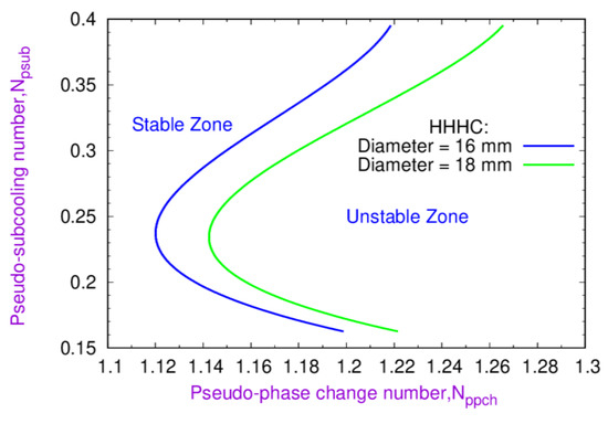
Figure 7.
Comparison of stability MSBs at two different diameters, i.e., 16 and 18 mm.
4.3. Effect of Hot Leg Length
The SCNCL flow regimes strongly depend on the hot leg length. In fact, upon increasing the loop’s mass flow rate, the gravitational driving force dominates at higher hot leg length rather than the friction resisting force. Hence, numerical simulations were performed to analyze the effect of hot leg on DWIs of the loop using three different hot leg lengths, i.e., 4.1, 5.1, and 6.1 m. The operating parameter and geometrical parameters, i.e., inlet system pressure (25.0 MPa) and diameter (14.0 mm), respectively, were kept constant for all simulations. Figure 8a,b show that the stable zone increased with an increase in hot leg length, and the stable regimes grew considerably from 4.1 to 5.1 m. However, at 6.1 m hot leg length, the stable regimes increased at a minimal rate compared to those at 5.1 m. At a higher hot leg length, more power is required to make the loop unstable if the coolant has the same inlet enthalpy.
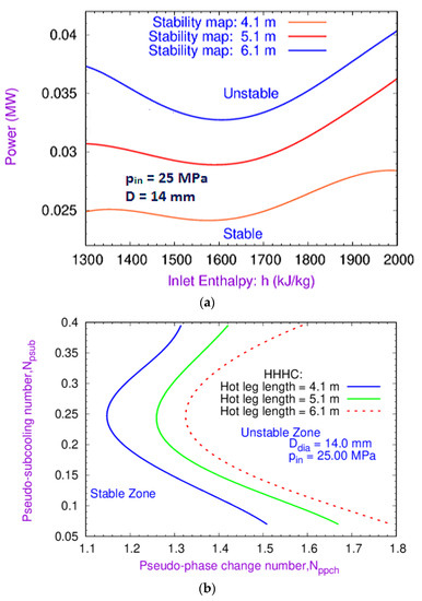
Figure 8.
Effect of hot leg length on the DWI of the loop: (a) specific enthalpy vs. power; (b) (Nppch) vs. (Npsub) plane.
4.4. Effect of Inlet System Pressure
The effect of three different inlet system pressures, i.e., 25.0, 27.5, and 30.0 MPa on the DWI of SCWNCL is shown in Figure 9a,b. Simulations were performed at these inlet system pressures keeping the loop diameter and riser height constant. It can be noted from Figure 9a that with the increase in system pressure from 25.0 to 30.0 MPa, the stable zone increases. It has also been observed that the MSB of DWI of the loop first slowly increases and subsequently becomes significant near the pseudocritical point. However, from Figure 9b, it can also be stated that at lower Npsub (which is the case when the temperature of the water at the channel inlet is close to the PCP), MSBs for different inlet pressures almost coincide with each other. However, the difference in MSBs becomes pronounced at higher Npsub, and the stability zone becomes reduced with the decrease in the inlet pressure. It should be noted that the increase in the exit pressure makes the BWR more stable [39,40,41], and a similar pattern is also observed for the SCWNCL.
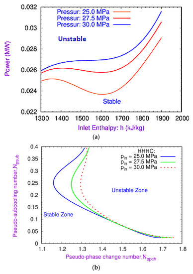
Figure 9.
Effect of pressure on the DWI of the loop: (a) specific enthalpy vs. power; (b) (Nppch) vs. (Npsub) plane.
4.5. Effect of Friction Factor
The effect of two different friction factors, namely Darcy and Churchill, on the DWI of SCWNCL is shown in Figure 10a,b, respectively. The simulations were performed using two different friction factors while keeping the loop diameter, riser height, and system pressure constant. The Churchill correlation shows the more stable MSB of DWI of the loop as compared to the Darcy friction factor, where the stability regime converges toward the experimental results. The stable regimes decreased with an increase in specific enthalpy up to the pseudocritical point. Afterward, the stable regimes increased with an increase in specific enthalpy. It can also be seen that the MSB obtained with the Churchill friction factor correlation is more stable than the Darcy friction factor. Figure 10b shows a small difference between the MSBs obtained by the Darcy friction factor and the Churchill friction factor at low and high values of Npsub. Churchill friction factor correlations predict a larger stable zone between the 0.25 to 0.30 Npsub than the Darcy friction factor.
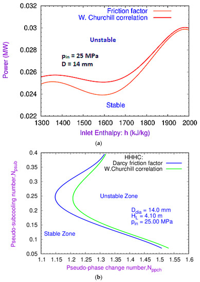
Figure 10.
Effect of the friction factor on the DWI of the loop: (a) specific enthalpy vs. power; (b) (Nppch) vs. (Npsub) plane.
5. Conclusions
In this study, a 1-D nonlinear thermal hydraulic model was validated by the experimental results of the SCWNCL. Initially, the numerical simulations were carried out to predict the occurrence of DWI in the SCWNCL and, thereafter, to predict the MSPs and draw the stability map. Two different stability maps were used to explore the stable and unstable regions. The first stability map was drawn between inlet-specific enthalpy and power, and the second was drawn between the dimensionless pseudo-phase change number and the pseudo-subcooling number. The key aspects of the present work according to the aforementioned results are as follows:
- The comparison indicates that the results obtained for the present model are justified by the experimental results, with a maximum error of .
- The possibility of DWI is found in the proposed operating regime of the loop.
- The MSPs were determined, and the locus of all the MSPs were connected and drawn, which bifurcates the stable and unstable zone of DWIs for the loop.
- The stable regimes of DWIs increase with an increase in loop diameter as well as loop hot leg length.
- As the loop system pressure increases, the stable zone of DWI slowly expands. By the time it approaches the pseudocritical point, the stable regimes expand even more. The high supplied power to mass flow rate ratio can make the SCWNCL less stable with increasing inlet pressure at a low Npsub value.
- The decrease in the inlet pressure can make the SCWNCL less stable, which is similar to BWRs.
- Perturbation of the loop’s friction factor yields two distinct stable zones, with the Darcy friction factor yielding a less stable zone than the Churchill friction factor correlation.
- The MSBs increase significantly at Npsub values between 0.2 to 0.3, with an increase in inlet pressure, loop diameter, and hot leg length.
Author Contributions
S.K.R.: investigation, methodology, project administration, resources, and software. N.A.: conceptualization and formal analysis. R.U.: conceptualization and formal analysis. P.K.: supervision and writing—review and editing. V.P.: supervision, data curation, validation, and visualization. All authors have read and agreed to the published version of the manuscript.
Funding
This research received no external funding.
Data Availability Statement
The study does not report any new data. Data sharing is not applicable to this article.
Conflicts of Interest
The authors declare that they have no known competing financial interests or personal relationships that could have appeared to influence the work reported in this paper.
Nomenclature
| a | acoustic speed, m/s |
| area, m2 | |
| eigenvalues of the matrix | |
| specific heat, J/kg K | |
| loop diameter, m | |
| D | source vector |
| specific internal energy, J/kg K | |
| specific flow energy J/kg | |
| gravitational acceleration, m/s2 | |
| loop height, m | |
| downcomer height, m | |
| riser height, m | |
| inlet-specific enthalpy, J/kg K | |
| specific enthalpy, J/kg K | |
| thermal conductivity, W/m K | |
| pressure, Pa | |
| heated perimeter, m | |
| inlet system pressure, Pa | |
| wetted perimeter, m | |
| heat flow rate, W | |
| heat flux, | |
| time, s | |
| temperature, °C | |
| velocity, m/s | |
| axial length, m | |
| Greek letters | |
| dynamic viscosity | |
| density, kg/m3 | |
| shear stress, N/m2 | |
| diagonal element of eigenvalues of the matrix | |
| Subscripts | |
| fluid | |
| in | inlet |
| outlet | |
| wall | |
| Dimensionless numbers | |
| Re | Reynolds number |
| Nppch | pseudo-phase change number |
| Npsub | pseudo-subcooling number |
| Heat transfer coefficient | W/m2 °C |
| Acronyms | |
| BC | boundary condition |
| BWR | boiling water reactor |
| CANDU | Canada deuterium uranium |
| CFD | computational fluid dynamics |
| DWI | density wave instability |
| DWO | density wave oscillation |
| MSB | marginal stability boundary |
| MSP | marginal stability point |
| NCL | natural circulation loop |
| NOLSTA | nonlinear stability analysis |
| NPP | nuclear power plant |
| PC | pseudocritical |
| PCP | pseudocritical point |
| SCP | supercritical phase |
| SCW | supercritical water |
| SCNCL | supercritical natural circulation loop |
| SCWNCL | supercritical water natural circulation loop |
| SCWR | supercritical water |
| SPORT | special predictions of reactor transients and stability |
| SUCLIN | supercritical linear stability code |
References
- Zvirin, Y. A review of natural circulation loops in pressurized water reactors and other systems. Nucl. Eng. Des. 1981, 67, 203–225. [Google Scholar] [CrossRef]
- Greif, R. Natural Circulation Loops. J. Heat Transf. 1988, 110, 1243–1258. [Google Scholar] [CrossRef]
- Usman, H.; Ali, H.M.; Arshad, A.; Ashraf, M.J.; Khushnood, S.; Janjua, M.M.; Kazi, S.N. An experimental study of PCM based finned and un-finned heat sinks for passive cooling of electronics. Heat Mass Transf. 2018, 54, 3587–3598. [Google Scholar] [CrossRef]
- Yamaguchi, H.; Sawada, N.; Suzuki, H.; Ueda, H.; Zhang, X.R. Preliminary Study on a Solar Water Heater Using Supercritical Carbon Dioxide as Working Fluid. J. Sol. Energy Eng. 2010, 132, 011010. [Google Scholar] [CrossRef]
- Kreitlow, D.B.; Reistad, G.M.; Miles, C.R.; Culver, G.G. Thermosyphon Models for Downhole Heat Exchanger Applications in Shallow Geothermal Systems. J. Heat Transf. 1978, 100, 713–719. [Google Scholar] [CrossRef]
- Dimmick, G.; Chatoorgoon, V.; Khartabil, H.; Duffey, R. Natural-convection studies for advanced CANDU reactor concepts. Nucl. Eng. Des. 2002, 215, 27–38. [Google Scholar] [CrossRef]
- Zappoli, B. Near-critical fluid hydrodynamics. C. R. Mec. 2003, 331, 713–726. [Google Scholar] [CrossRef]
- Pioro, I.L.; Khartabil, H.F.; Duffey, R.B. Heat transfer to supercritical fluids flowing in channels—Empirical correlations (survey). Nucl. Eng. Des. 2004, 230, 69–91. [Google Scholar] [CrossRef]
- Cheng, X.; Schulenberg, T. Heat Transfer at Supercritical Pressures—Literature Review and Application to an HPLWR; FZKA 6609; Forschungszentrum Karlsruhe GmbH: Karlsruhe, Germany, 2001. [Google Scholar]
- Bushby, S.J.; Dimmick, G.; Duffey, R.; Spinks, N.; Burrill, K.; Chan, P. Conceptual designs for advanced, high-temperature CANDU reactors. In Proceedings of the First International Symposium on Supercritical Water-Cooled Reactors, Design and Technology (SCR-2000), Tokyo, Japan, 6–9 November 2000. [Google Scholar]
- Silin, V.; Voznesensky, V.; Afrov, A. The light water integral reactor with natural circulation of the coolant at supercritical pressure B-500 SKDI. Nucl. Eng. Des. 1993, 144, 327–336. [Google Scholar] [CrossRef]
- Sarkar, M.K.; Tilak, A.; Basu, D.N. A state-of-the-art review of recent advances in supercritical natural circulation loops for nuclear applications. Ann. Nucl. Energy 2014, 73, 250–263. [Google Scholar] [CrossRef]
- Rai, S.K.; Dutta, G. A Review of Recent Applications of Supercritical Fluid in Natural Circulation Loops for Nuclear Reactor. Int. J. Appl. Eng. Res. 2018, 23, 195–204. [Google Scholar]
- Rai, S.K.; Kumar, P.; Panwar, V. A literature review of static instability in supercritical fluid natural circulation loop. In Proceedings of the Advances in Thermal-Fluid Engineering (ATFE-2021), Gandhinagar, India, 25–26 March 2021. [Google Scholar]
- Thippeswamy, L.R.; Yadav, A.K. Heat transfer enhancement using CO2 in a natural circulation loop. Sci. Rep. 2020, 10, 1507. [Google Scholar] [CrossRef] [PubMed]
- Ambrosini, W.; Sharabi, M. Dimensionless Parameters in Stability Analysis of Heated Channels with Fluids at Supercritical Pressures. Nucl. Eng. Des. 2008, 238, 1917–1929. [Google Scholar] [CrossRef]
- Chatoorgoon, V. Stability of supercritical fluid flow in a single-channel natural-convection loop. Int. J. Heat Mass Transf. 2001, 44, 1963–1972. [Google Scholar] [CrossRef]
- Chatoorgoon, V.; Voodi, A.; Fraser, D. The stability boundary for supercritical flow in natural convection loops: Part I: H2O studies. Nucl. Eng. Des. 2005, 235, 2570–2580. [Google Scholar] [CrossRef]
- Chatoorgoon, V.; Voodi, A.; Upadhye, P. The stability boundary for supercritical flow in natural-convection loops: Part II: CO2 and H2. Nucl. Eng. Des. 2005, 235, 2581–2593. [Google Scholar] [CrossRef]
- Jain, P.K.; Uddin, R. Numerical analysis of supercritical flow instabilities in a natural circulation loop. Nucl. Eng. Des. 2008, 238, 1947–1957. [Google Scholar] [CrossRef]
- Vijayan, P.K.; Sharma, M.; Pilkhwal, D.S.; Saha, D.; Sinha, R.K. A Comparative Study of Single-Phase, Two-Phase, and Supercritical Natural Circulation in a Rectangular Loop. J. Eng. Gas Turbines Power 2010, 132, 102913. [Google Scholar] [CrossRef]
- Vijayan, P.K.; Sharma, M.; Pilkhwal, D.S. Steady State and Stability Characteristics of a Supercritical Natural Circulation Loop (SPNCL) with CO2; BARC/2013/E/003; Bhabha Atomic Research Centre: Mumbai, India, 2013. [Google Scholar]
- Sharma, M.; Vijayan, P.K.; Pilkhwal, D.S.; Saha, D.; Sinha, R.K. Linear and Non-Linear Stability Analysis of a Supercritical Natural Circulation Loop. J. Eng. Gas Turbines Power 2010, 132, 102904. [Google Scholar] [CrossRef]
- Sharma, M.; Pilkhwal, D.; Vijayan, P.; Saha, D.; Sinha, R. Steady state and linear stability analysis of a supercritical water natural circulation loop. Nucl. Eng. Des. 2010, 240, 588–597. [Google Scholar] [CrossRef]
- Chen, L.; Deng, B.-L.; Jiang, B.; Zhang, X.-R. Thermal and hydrodynamic characteristics of supercritical CO2 natural circulation in closed loops. Nucl. Eng. Des. 2013, 257, 21–30. [Google Scholar] [CrossRef]
- Tilak, A.K.; Basu, D.N. Computational investigation of the dynamic response of a supercritical natural circulation loop to aperiodic and periodic excitations. Nucl. Eng. Des. 2015, 284, 251–263. [Google Scholar] [CrossRef]
- Krishnani, M.; Basu, D.N. Computational stability appraisal of rectangular natural circulation loop: Effect of loop inclination. Ann. Nucl. Energy 2017, 107, 17–30. [Google Scholar] [CrossRef]
- Goudarzi, N.; Talebi, S. Heat removal ability for different orientations of single-phase natural circulation loops using the entransy method. Ann. Nucl. Energy 2018, 111, 509–522. [Google Scholar] [CrossRef]
- Deng, B.; Chen, L.; Zhang, X.; Jin, L. The flow transition characteristics of supercritical CO2 based closed natural circulation loop (NCL) system. Ann. Nucl. Energy 2019, 132, 134–148. [Google Scholar] [CrossRef]
- Wahidi, T.; Chandavar, R.A.; Yadav, A.K. Supercritical CO2 flow instability in natural circulation loop: CFD analysis. Ann. Nucl. Energy 2021, 160, 108374. [Google Scholar] [CrossRef]
- Dutta, G.; Zhang, C.; Jiang, J. Analysis of flow induced density wave oscillations in the CANDU supercritical water reactor. Nucl. Eng. Des. 2015, 286, 150–162. [Google Scholar] [CrossRef]
- Rai, S.K.; Kumar, P.; Panwar, V. Numerical analysis of influence of geometry and operating parameters on Ledinegg and dynamic instability on supercritical water natural circulation loop. Nucl. Eng. Des. 2020, 369, 110830. [Google Scholar] [CrossRef]
- Rai, S.K.; Kumar, P.; Panwar, V. Mathematical and numerical investigation of Ledinegg flow excursion and dynamic instability of natural circulation loop at supercritical condition. Ann. Nucl. Energy 2021, 155, 108129. [Google Scholar]
- Upadhyay, R.; Rai, S.K.; Dutta, G. Numerical analysis of density wave instability and heat transfer deterioration in a supercritical water reactor. J. Mech. Sci. Technol. 2018, 32, 1063–1070. [Google Scholar] [CrossRef]
- Rai, S.K.; Dutta, G.; Sheorey, T. Stability Analysis of Supercritical Water Natural Circulation Loop with Vertical Heater and Cooler. In Proceedings of the 24th National and 2nd International ISHMT-ASTFE Heat and Mass Transfer Conference (IHMTC-2017), Hyderabad, India, 27–30 December 2017. [Google Scholar]
- Rai, S.K.; Kumar, P.; Panwar, V. Numerical investigation of steady state characteristics and stability of supercritical water natural circulation loop of a heater and cooler arrangements. Nucl. Eng. Technol. 2021, 53, 3597–3611. [Google Scholar] [CrossRef]
- Rai, S.K.; Ahlawat, N.; Kumar, P.; Panwar, V. Mathematical modeling and numerical investigation of density wave instability of supercritical natural circulation loop. In Proceedings of the XIII International Conference on Computational Heat, Heat, Mass and Momentum Transfer (ICCHMT 2021), Paris, France, 18–21 May 2021. [Google Scholar]
- Sharma, M.; Vijayan, P.K.; Pilkhwal, D.S.; Asako, Y. Natural convective flow and heat transfer studies for supercritical water in a rectangular circulation loop. Nucl. Eng. Des. 2014, 273, 304–320. [Google Scholar] [CrossRef]
- Boure, J.A.; Bergles, A.E.; Tong, L.S. Review of two-phase flow instability. Nucl. Eng. Des. 1973, 25, 165–192. [Google Scholar] [CrossRef]
- Hsieh, C.L.; Lin, H.T.; Wang, J.R.; Chiang, S.C.; Weng, T.L.; Shih, C. BWR paramet-ric sensitivity effect of regional mode instability on stability boundary. J. Power Energy Syst. 2008, 2, 361–370. [Google Scholar] [CrossRef][Green Version]
- Fang, X.D.; Xu, Y.; Zhou, Z.R. New correlations of single-phase friction factorfor turbulent pipe flow and evaluation of existing single-phase friction factor correlations. Nucl. Eng. Des. 2011, 241, 897–902. [Google Scholar] [CrossRef]
Publisher’s Note: MDPI stays neutral with regard to jurisdictional claims in published maps and institutional affiliations. |
© 2022 by the authors. Licensee MDPI, Basel, Switzerland. This article is an open access article distributed under the terms and conditions of the Creative Commons Attribution (CC BY) license (https://creativecommons.org/licenses/by/4.0/).