
Enhancing Safety in U.S. Coal Mines Through a Rib Support Recommendation Tool

 , , ,
, , ,
Abstract
1. Introduction
2. Materials and Methods
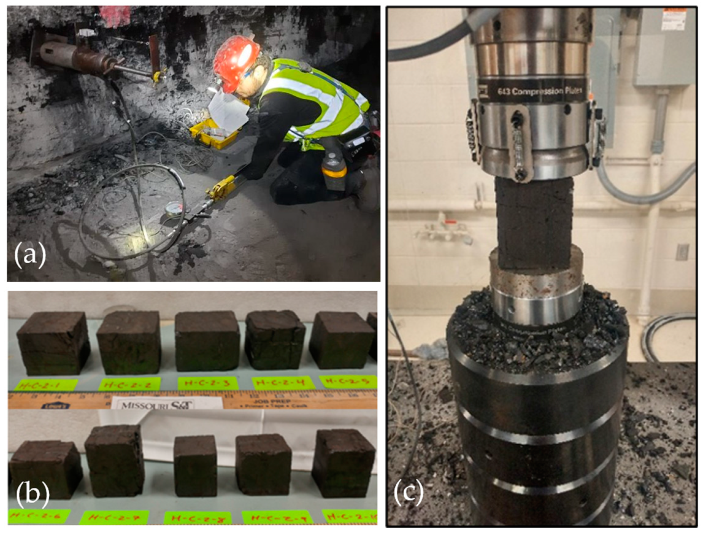
2.1. Laboratory Experiment and Field Testing
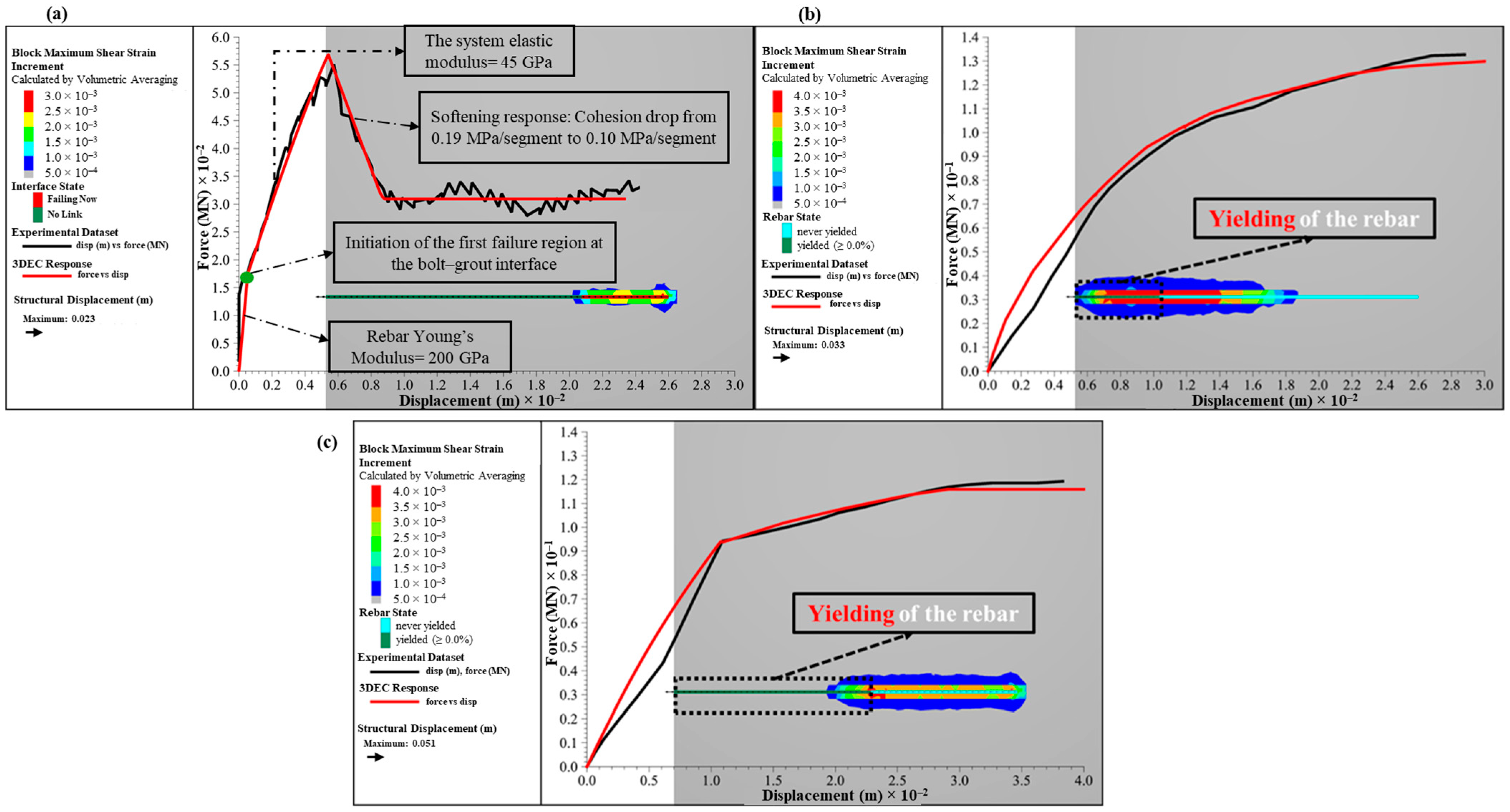
2.2. Numerical Model and Calibration
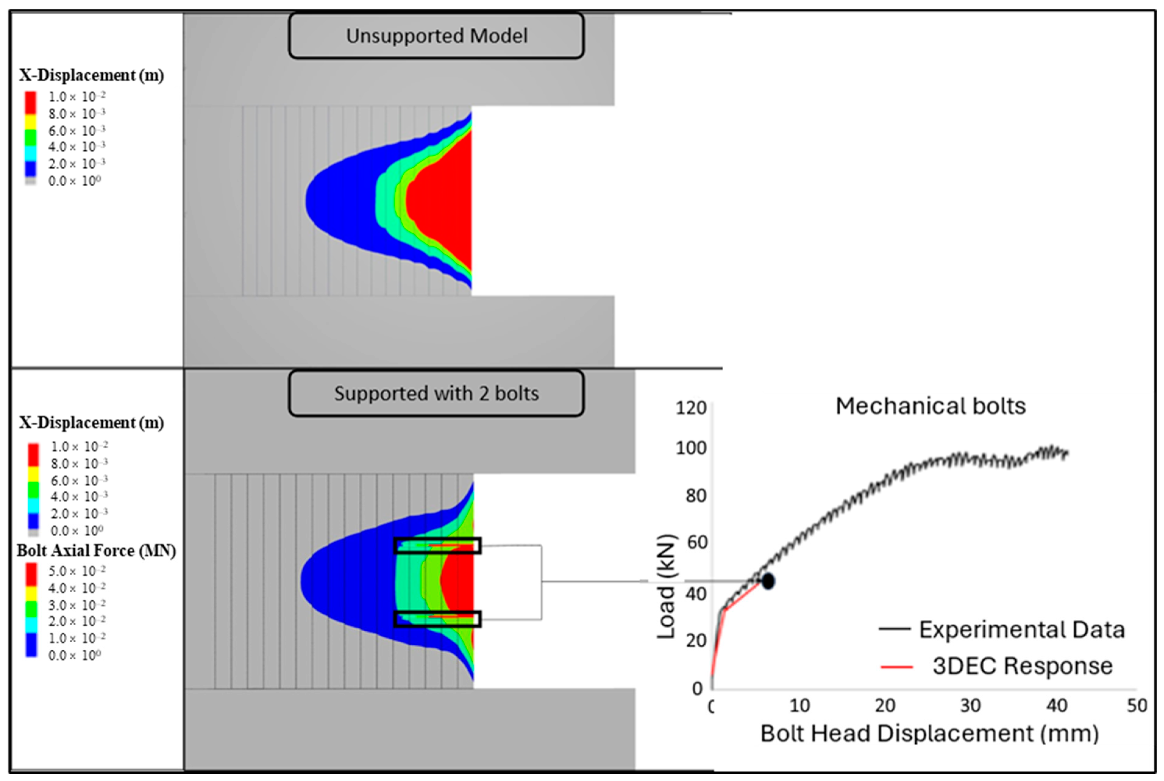
2.3. Implementation of Bolt Responses into Coal Rib Model
2.4. Parametric Studies for Different Geological Conditions
3. Results
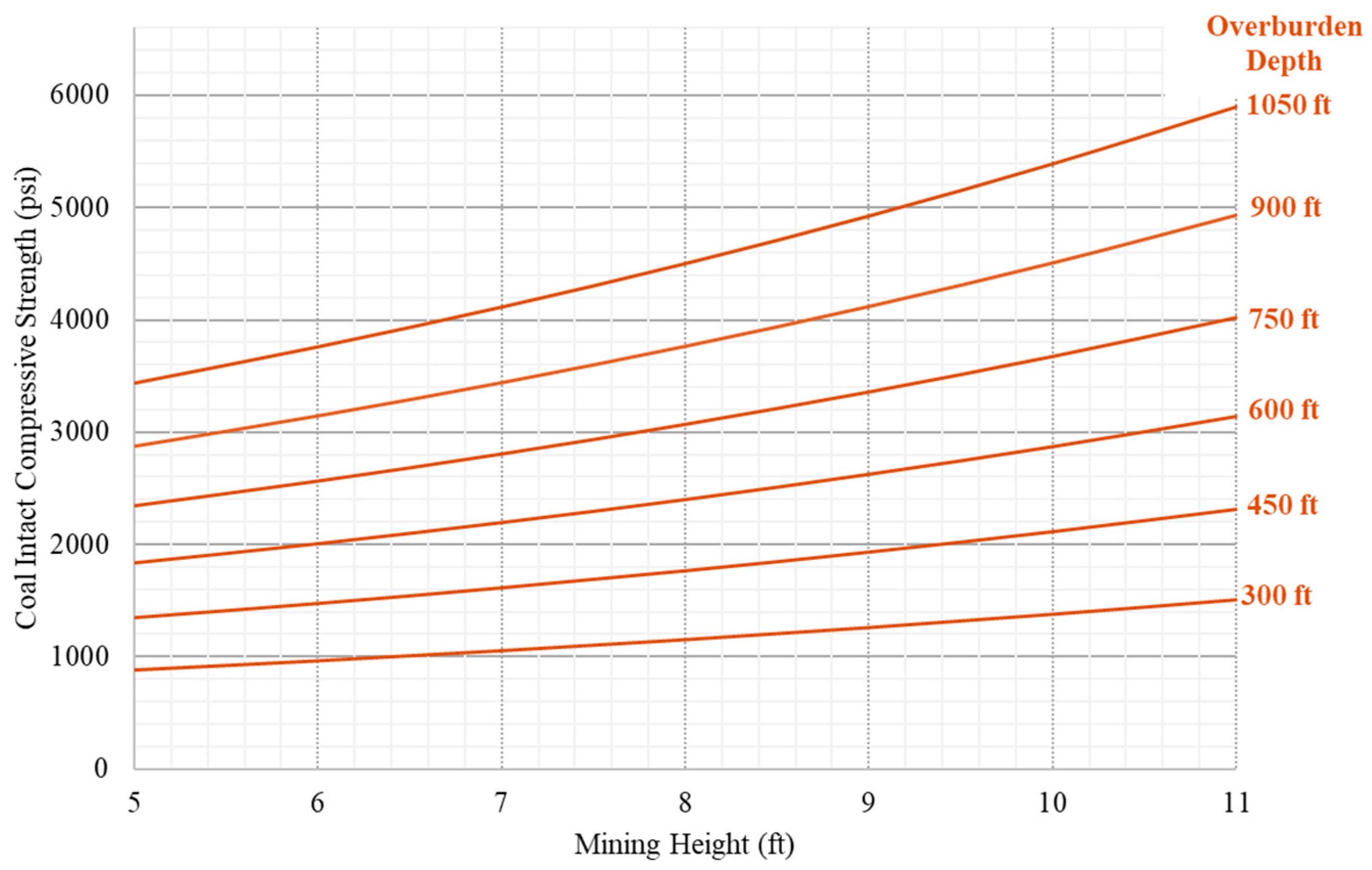
3.1. Category 1—Coal Lithotypes with Varying Overburden Depths and Mining Heights for Single-Solid Coal Rib
3.2. Categories 2 and 3—Coal Lithotypes with Varying Overburden Depths and Mining Heights for Multiple Coal Units
3.2.1. Parametric Model Results for Category 2
3.2.2. Parametric Model Results for Category 3
3.3. In-Seam Rock Parting (Category 4)
3.4. Weak and Moderate Roof and Floor Conditions:
- Weak roof and strong floor: roof with CMRR 30 with an elastic, non-yielding floor;
- Moderate roof and strong floor: the roof is simulated with a CMRR value of 50, while the floor remains elastic;
- Weak roof and weak floor: both the roof (CMRR 30) and floor are simulated by weak material properties;
- Moderate roof and weak floor: the roof is simulated with a CMRR value of 50, while the floor is weak;
- Strong roof and weak floor: the roof is elastic, while the floor is modeled as weak and deformable.
4. Development of Rib Support Recommendation (RSR) Tool
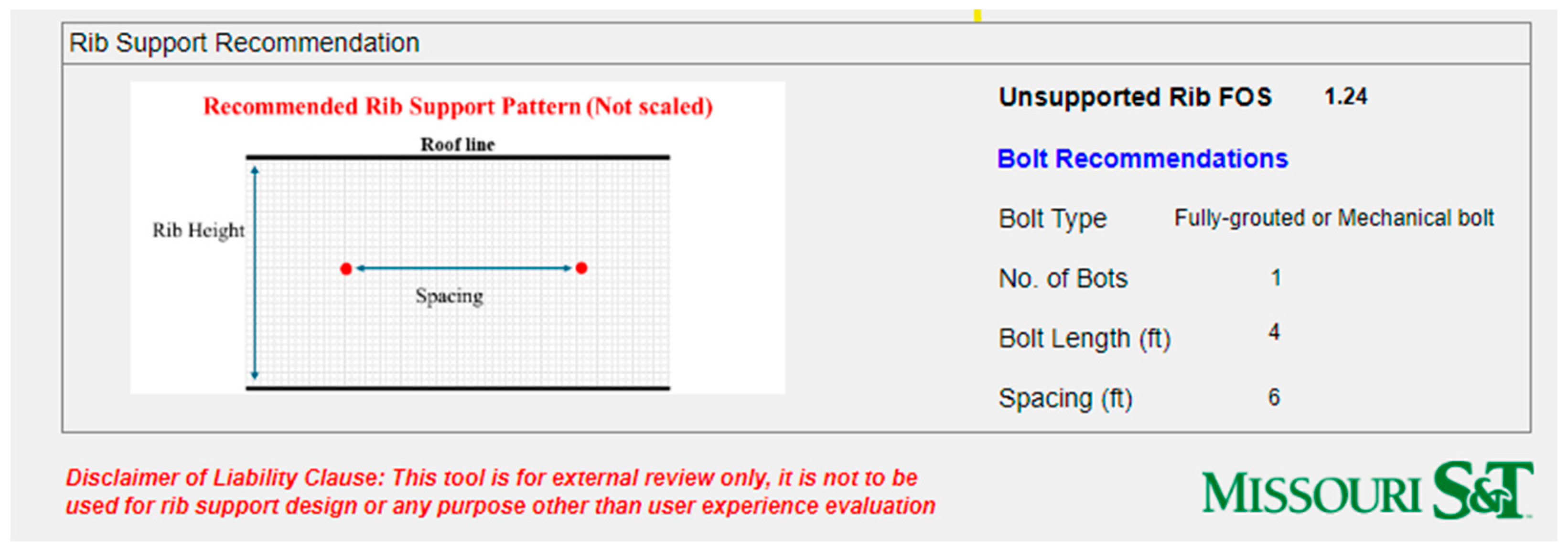
Application of Developed Rib Support Recommendations
5. Conclusions
- Field pull-out tests were conducted on various bolt types, generating complex response data. These data were used to calibrate bolt parameters in numerical models, enhancing their accuracy and realism, particularly in simulating the interaction between bolts and coal ribs. The calibrated models were validated against field observations to ensure realistic support performance, which then informed more accurate parametric modeling;
- This study identifies that the Rib Support Density (RSD) alone is inadequate as a design parameter. It does not account for the effectiveness of different bolt configurations under varying conditions such as the Coal Pillar Rib Rating (CPRR), mining height, and overburden depth. This finding challenges the traditional reliance on RSD and underscores the need for tailored, case-specific support recommendations to ensure safety and efficiency in mining operations;
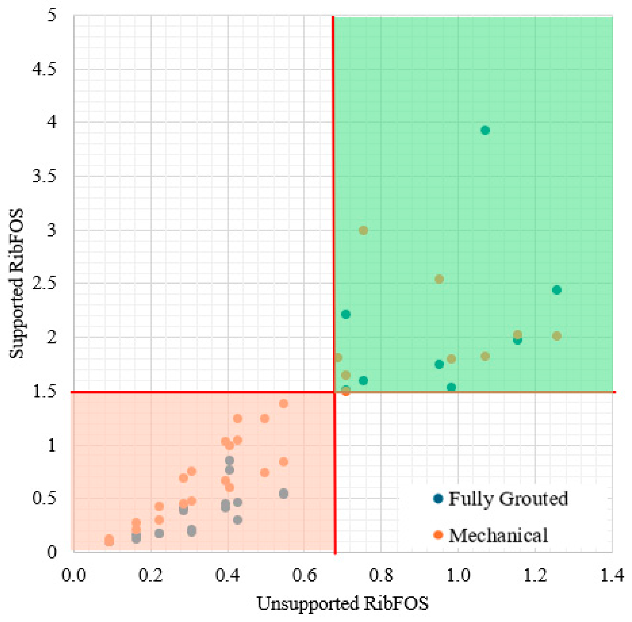
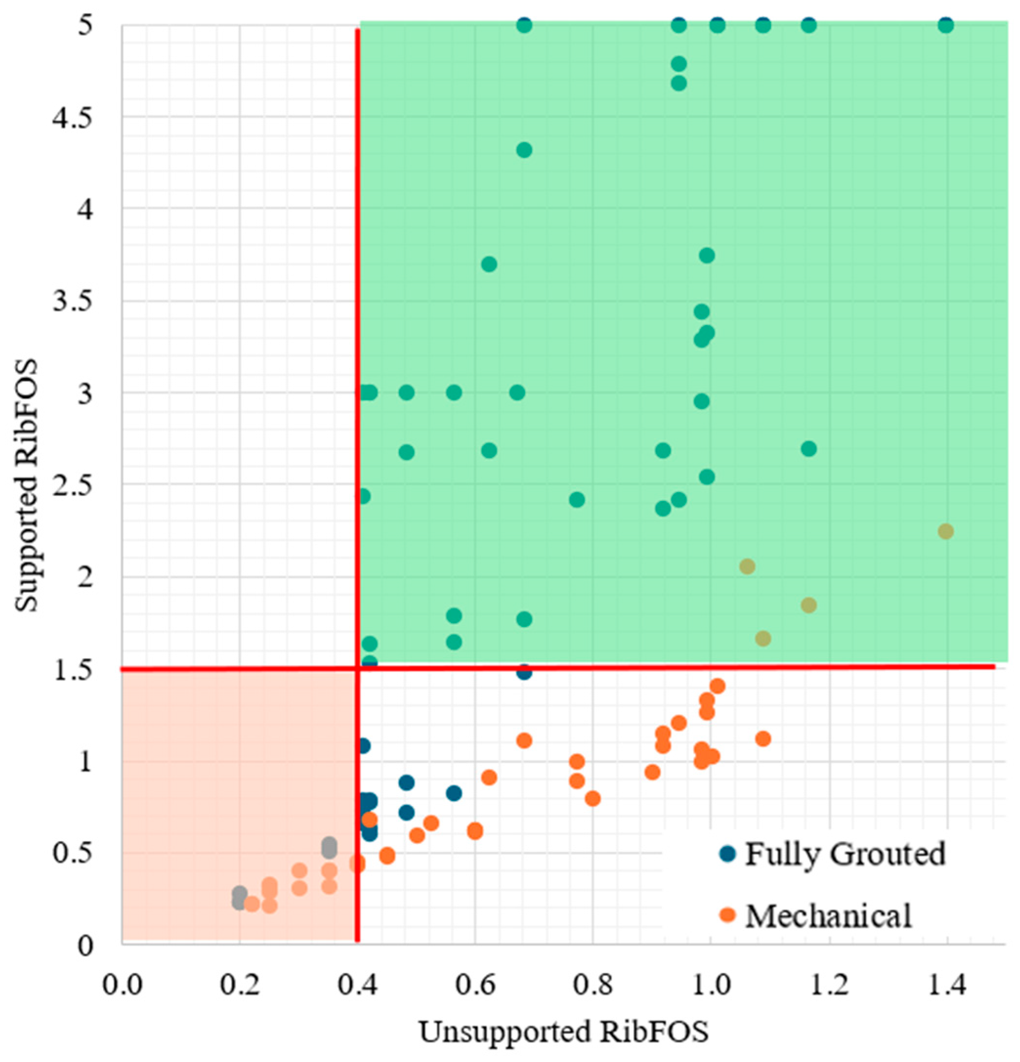
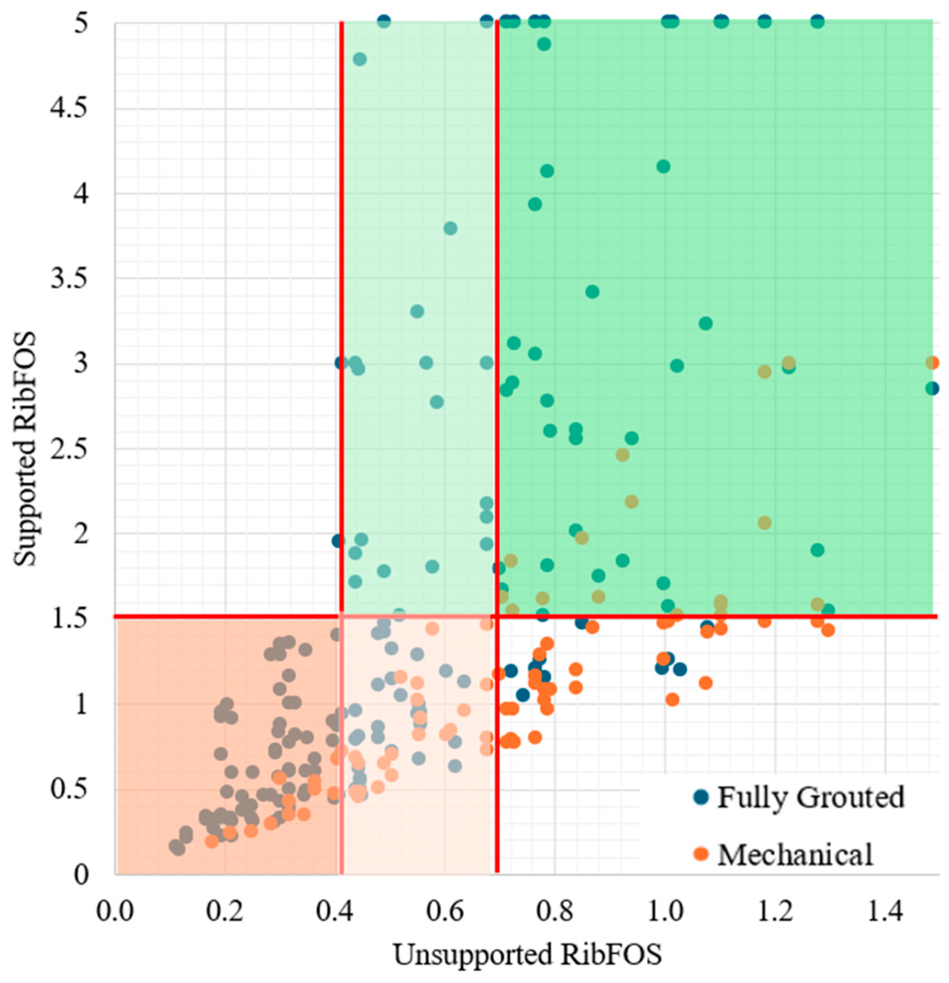
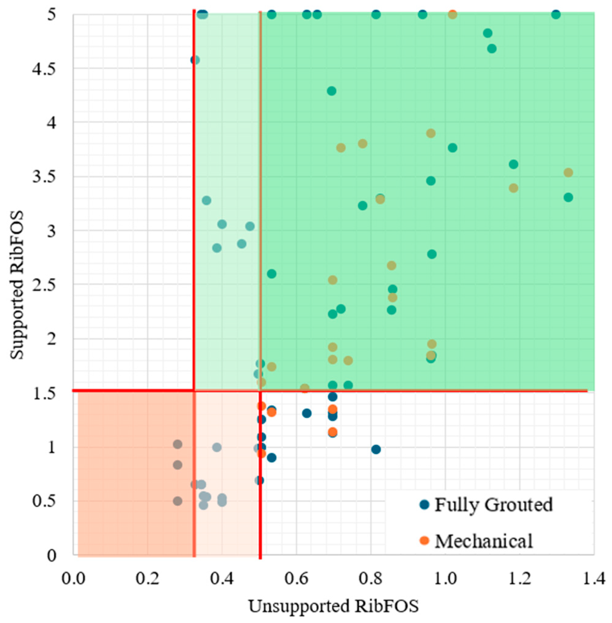
- A detailed case-by-case evaluation of the parametric models led to the categorization of rib support systems into four distinct groups, each associated with specific support recommendation tables. Minimum threshold values of the Unsupported Rib Factor of Safety (RibFOS) were established, marking the operational limits for rib support systems. For example, a RibFOS of 0.7 was set as a critical threshold for solid coal ribs, while a value of 0.3 was identified for ribs with rock partings;
- Over 30 distinct rib support recommendation classes were identified, primarily determined by the mining height and unsupported RibFOS, which depend on factors like CPRR and overburden depth. In more complex scenarios, this study introduced the critical coal strength (CCS) concept to refine the classification accuracy. CCS estimates the compressive strength of coal below which failure is likely to occur under certain conditions, integrating the overburden depth and mining height into the analysis;
- Mechanical bolts were found effective under certain adverse conditions, such as high mining heights and significant overburden depth, particularly in strong solid coal ribs without interfaces or partings. However, their performance was limited in weaker or thinner coal units. This study incorporates CCS and critical coal unit thickness into support recommendation classifications to better address these limitations. It suggests that mechanical bolts can be effective if the coal strength exceeds 1750–2000 psi in conditions with rock partings;
- Recognizing the complexity of rib support classifications, this study developed the rib support recommendation tool (RSR), a standalone application designed to simplify the process of determining optimal rib support strategies. The RSR tool integrates the extensive rib support recommendation classes derived from parametric models and accounts for a wide range of scenarios and influencing factors;
- In two applied cases, the rib support recommendations provided by the RSR tool showed significant potential. However, this study emphasizes that the widespread adoption of this methodology among mining professionals will require extensive validation across a broad spectrum of real-world cases.
Author Contributions
Funding
Data Availability Statement
Conflicts of Interest
References
- Heritage, Y. Mechanics of rib deformation—Observations and monitoring in Australian coal mines. Int. J. Min. Sci. Technol. 2019, 29, 119–129. [Google Scholar] [CrossRef]
- Colwell, M.; Frith, R. ALTS 2009-a Ten Year Journey; University of Wollongong: Wollongong, Australia, 2009. [Google Scholar]
- Kang, H.; Wang, J. Rock Bolting Theory and Complete Technology for Coal Roadways; China Coal Industry Publishing House: Beijing, China, 2007. [Google Scholar]
- Xiangjun, M. Solid coal rib support technology of fully-mechanized mining along gob-side entry driving based on main roof fracture location. Coal Sci. Technol. 2020, 48, 61–67. [Google Scholar]
- Mark, C. Ground control in South African coal mines—A US perspective. In Proceedings of the Proceedings, 18th International Conference on Ground Control in Mining, Morgantown, WV, USA, 3–5 August 1999; pp. 186–193. [Google Scholar]
- Bastami, M.; Shahriar, K.; Ghadimi, M. Verification of the analytical model for fully grouted rock bolts based on pull-out test (Case study: Tabas coal mine). In Proceedings of the ISRM European Rock Mechanics Symposium—EUROCK 2017, Ostrava, Czech Republic, 20–22 June 2017. [Google Scholar]
- Cox, R.H.; Fuller, P. Load Transfer Behaviour Between Steel Reinforcement and Cement Based Grout; National Library of Australia: Canberra, Australia, 1977. [Google Scholar]
- Schmuck, C. Cable bolting at the Homestake gold mine. Min. Eng. 1979, 31, 1677–1681. [Google Scholar]
- Jin-feng, Z.; Peng-hao, Z. Analytical model of fully grouted bolts in pull-out tests and in situ rock masses. Int. J. Rock Mech. Min. Sci. 2019, 113, 278–294. [Google Scholar] [CrossRef]
- Li, X.; Aziz, N.; Mirzaghorbanali, A.; Nemcik, J. Behavior of fiber glass bolts, rock bolts and cable bolts in shear. Rock Mech. Rock Eng. 2016, 49, 2723–2735. [Google Scholar] [CrossRef]
- Mohamed, K.M.; Murphy, M.M.; Lawson, H.E.; Klemetti, T. Analysis of the current rib support practices and techniques in U.S. coal mines. Int. J. Min. Sci. Technol. 2016, 26, 77–87. [Google Scholar] [CrossRef] [PubMed]
- Kılıc, A.; Yasar, E.; Celik, A.G. Effect of grout properties on the pull-out load capacity of fully grouted rock bolt. Tunn. Undergr. Space Technol. 2002, 17, 355–362. [Google Scholar] [CrossRef]
- Blanco Martín, L.; Tijani, M.; Hadj-Hassen, F.; Noiret, A. Assessment of the bolt-grout interface behaviour of fully grouted rockbolts from laboratory experiments under axial loads. Int. J. Rock Mech. Min. Sci. 2013, 63, 50–61. [Google Scholar] [CrossRef]
- Chen, J.; Hagan, P.C.; Saydam, S. Parametric study on the axial performance of a fully grouted cable bolt with a new pull-out test. Int. J. Min. Sci. Technol. 2016, 26, 53–58. [Google Scholar] [CrossRef]
- Du, Y.-l.; Feng, G.-r.; Kang, H.-p.; Zhang, Y.-j.; Zhang, X.-h. Effects of different pull-out loading rates on mechanical behaviors and acoustic emission responses of fully grouted bolts. J. Cent. South Univ. 2021, 28, 2052–2066. [Google Scholar] [CrossRef]
- Thenevin, I.; Blanco-Martín, L.; Hadj-Hassen, F.; Schleifer, J.; Lubosik, Z.; Wrana, A. Laboratory pull-out tests on fully grouted rock bolts and cable bolts: Results and lessons learned. J. Rock Mech. Geotech. Eng. 2017, 9, 843–855. [Google Scholar] [CrossRef]
- Han, J.; Bi, Z.; Liang, B.; Cao, C.; Ma, S. Anchorage performance of large-diameter FRP bolts and their application in large deformation roadway. Int. J. Min. Sci. Technol. 2023, 33, 1037–1043. [Google Scholar] [CrossRef]
- Mohamed, K.; Rashed, G.; Radakovic-Guzina, Z. Loading characteristics of mechanical rib bolts determined through testing and numerical modeling. Int. J. Min. Sci. Technol. 2020, 30, 17–24. [Google Scholar] [CrossRef] [PubMed]
- Chen, J.; Saydam, S.; Hagan, P.C. Numerical simulation of the pull-out behaviour of fully grouted cable bolts. Constr. Build. Mater. 2018, 191, 1148–1158. [Google Scholar] [CrossRef]
- Chen, J.; Li, D. Numerical simulation of fully encapsulated rock bolts with a tri-linear constitutive relation. Tunn. Undergr. Space Technol. 2022, 120, 104265. [Google Scholar] [CrossRef]
- Saadat, M.; Taheri, A. Effect of contributing parameters on the behaviour of a bolted rock joint subjected to combined pull-and-shear loading: A DEM approach. Rock Mech. Rock Eng. 2020, 53, 383–409. [Google Scholar] [CrossRef]
- Chen, J.; Liu, L.; Zeng, B.; Tao, K.; Zhang, C.; Zhao, H.; Li, D.; Zhang, J. A constitutive model to reveal the anchorage mechanism of fully bonded bolts. Rock Mech. Rock Eng. 2023, 56, 1739–1757. [Google Scholar] [CrossRef]
- Jahangir, E.; Blanco-Martín, L.; Hadj-Hassen, F.; Tijani, M. Development and application of an interface constitutive model for fully grouted rock-bolts and cable-bolts. J. Rock Mech. Geotech. Eng. 2021, 13, 811–819. [Google Scholar] [CrossRef]
- Ma, S.; Zhao, Z.; Nie, W.; Gui, Y. A numerical model of fully grouted bolts considering the tri-linear shear bond–slip model. Tunn. Undergr. Space Technol. 2016, 54, 73–80. [Google Scholar] [CrossRef]
- Nemcik, J.; Ma, S.; Aziz, N.; Ren, T.; Geng, X. Numerical modelling of failure propagation in fully grouted rock bolts subjected to tensile load. Int. J. Rock Mech. Min. Sci. 2014, 71, 293–300. [Google Scholar] [CrossRef]
- Hyett, A.J.; Bawden, W.F.; Reichert, R.D. The effect of rock mass confinement on the bond strength of fully grouted cable bolts. Int. J. Rock Mech. Min. Sci. Geomech. Abstr. 1992, 29, 503–524. [Google Scholar] [CrossRef]
- Xu, C.; Li, Z.; Wang, S.; Wang, S.; Fu, L.; Tang, C. Pullout performances of grouted rockbolt systems with bond defects. Rock Mech. Rock Eng. 2018, 51, 861–871. [Google Scholar] [CrossRef]
- Nie, W.; Guo, W.; Ma, S.; Zhao, Z. Numerical modelling of fully grouted rockbolts subjected to shear load. Rock Mech. Rock Eng. 2020, 53, 2493–2503. [Google Scholar] [CrossRef]
- Luga, E.; Periku, E. A pioneer in-situ investigation on the bearing capacity and failure causes of real scale fully grouted rockbolts. Constr. Build. Mater. 2021, 310, 124826. [Google Scholar] [CrossRef]
- Ma, S.; Zhao, Z.; Nie, W.; Zhu, X. An analytical model for fully grouted rockbolts with consideration of the pre- and post-yielding behavior. Rock Mech. Rock Eng. 2017, 50, 3019–3028. [Google Scholar] [CrossRef]
- Nie, W. Reinforcement Mechanism of Rockbolt System for Underground Excavation. Doctoral Thesis, Nanyang Technological University, Singapore, 2019. [Google Scholar]
- Giot, R.; Auvray, C.; Raude, S.; Giraud, A. Experimental and numerical analysis of in situ pull-out tests on rock bolts in claystones. Eur. J. Environ. Civ. Eng. 2021, 25, 2277–2300. [Google Scholar] [CrossRef]
- Chen, J.; Zhao, H.; He, F.; Zhang, J.; Tao, K. Studying the performance of fully encapsulated rock bolts with modified structural elements. Int. J. Coal Sci. Technol. 2021, 8, 64–76. [Google Scholar] [CrossRef]
- Tulu, I.B.; Esterhuizen, G.S.; Heasley, K.A. Calibration of FLAC3D to simulate the shear resistance of fully grouted rock bolts. In Proceedings of the 46th U.S. Rock Mechanics/Geomechanics Symposium, Chicago, IL, USA, 24–27 June 2012. [Google Scholar]
- Kirmaci, A.; Guner, D.; Karadeniz, K.E.; Wijesinghe, D.R.; Sherizadeh, T. Examining coal rib stability using mechanical bolts: An experimental and numerical study. Int. J. Geomech. 2024. accepted. [Google Scholar]
- Mohamed, K.; Xue, Y.; Guner, D.; Kirmaci, A.; Sherizadeh, T. Examining pull-out tests for grouted rib bolts: A comprehensive analysis. In Proceedings of the SME Annual Conference & EXPO, Phoenix, AZ, USA, 25–28 February 2024. [Google Scholar]
- Mohamed, K.M.; Tulu, I.B.; Klemetti, T. Numerical simulation of deformation and failure process of coal-mass. In Proceedings of the 49th U.S. Rock Mechanics/Geomechanics Symposium, San Francisco, CA, USA, 29 June–1 July 2015. [Google Scholar]
- Guner, D.; Sherizadeh, T.; Nowak, S.; Karadeniz, K.E.; Sunkpal, M. Distinct element analysis for the effectiveness of preliminary coal pillar rib support systems based on the strength reduction method using coal mass constitutive model. Min. Metall. Explor. 2023, 40, 1535–1546. [Google Scholar] [CrossRef]
- Rashed, G.; Sears, M.; Addis, J.; Mohamed, K.; Wickline, J. A case-study of roof support alternatives for deep cover room-and-pillar retreat mining using in-situ monitoring and numerical modeling. In Proceedings of the SME Annual Meeting, Denver, CO, USA, 24–27 February 2019; pp. 25–28. [Google Scholar]
- Liu, H.; Sang, S.; Xue, J.; Wang, G.; Xu, H.; Ren, B.; Liu, C.; Liu, S. Characteristics of an in situ stress field and its control on coal fractures and coal permeability in the Gucheng block, Southern Qinshui basin, China. J. Nat. Gas Sci. Eng. 2016, 36, 1130–1139. [Google Scholar] [CrossRef]
- Esterhuizen, G.S. (National Institute for Occupational Safety and Health, Pittsburgh Mining Research Division, Pittsburgh, USA). Personal communication, 2017.
- Xue, Y.; Mohamed, K.M. Stability analysis of coal rib with rock parting based on the strength reduction of the coal mass model. In Proceedings of the 55th U.S. Rock Mechanics/Geomechanics Symposium, Online, 18–25 June 2021. [Google Scholar]
- Carranza-Torres, C. Analytical and numerical study of the mechanics of rockbolt reinforcement around tunnels in rock masses. Rock Mech. Rock Eng. 2009, 42, 175–228. [Google Scholar] [CrossRef]
- Sherizadeh, T. Reducing Rib Hazards in Underground Coal Mines by Improvement of the Coal Pillar Rib Rating (CPRR) System. 2023. Alpha Foundation for the Improvement of Mine Safety and Health, Final Technical Report (AFCRFP20 -112). Available online: https://www.alpha-foundation.org/wp-content/uploads/2023/07/AFCRFP20-112_MST_FinalRpt.pdf (accessed on 7 January 2025).
- Sherizadeh, T.; Dogukan, G.; Kutay, E.K.; Samuel, N.; Alper, K. A New Strain-Softening Anisotropic Constitutive Model for Coal Mine Roof Simulation. In Proceedings of the 42nd International Conference on Ground Control in Mining, Canonsburg, PA, USA, 24–27 July 2023. [Google Scholar]

| ID | H (mm) | W1 (mm) | W2 (mm) | W/H | UCS (MPa) | Young’s Modulus (MPa) |
|---|---|---|---|---|---|---|
| 1 | 57.15 | 58.06 | 62.46 | 1.05 | 18.83 | 1383 |
| 2 | 56.33 | 62.61 | 64.48 | 1.13 | 23.54 | 1956 |
| 3 | 54.54 | 58.10 | 74.42 | 1.21 | 19.94 | 1659 |
| 4 | 55.31 | 55.24 | 56.93 | 1.01 | 19.85 | 920 |
| 5 | 51.63 | 53.58 | 53.66 | 1.04 | 17.15 | 1671 |
| 6 | 48.55 | 54.15 | 61.02 | 1.19 | 21.32 | 1857 |
| 7 | 68.27 | 49.67 | 52.66 | 0.75 | 19.98 | 1982 |
| 8 | 55.30 | 54.29 | 46.76 | 0.91 | 18.50 | 1381 |
| 9 | 52.57 | 50.99 | 51.38 | 0.97 | 17.31 | 1689 |
| Avg | 19.6 | 1611 | ||||
| Std. Dev. | 2.0 | 338 |
| Bolt ID (#) | Bolt Length (ft) | Pre-Tension Force (kN) | Force on Initial Critical Point (kN) | Bolt Yield Capacity (kN) |
|---|---|---|---|---|
| 1 | 4 | 24.5 | 41.5 | 83.4 |
| 2 | 26.3 | 43.4 | 97.6 | |
| 3 | 18.2 | 30.5 | 61.8 | |
| 4 | 17.5 | 31.6 | 93.9 | |
| 5 * | - | - | 57.8 | |
| Average | 21.6 ± 4.4 | 36.8 ± 6.6 | 78.9 ± 18.3 | |
| 6 | 5 | 20.1 | 36.7 | 79.7 |
| 7 | 20.9 | 47.0 | 89.7 | |
| 8 | 21.1 | 40.7 | 77.7 | |
| 9 | 23.2 | 50.3 | 89.7 | |
| 10 | 32.3 | 44.7 | 77.7 | |
| Average | 23.5 ± 5.1 | 43.9 ± 5.3 | 82.9 ± 6.3 | |
| Parameter | Range |
|---|---|
| Overburden depth | 300 to 1050 ft |
| Rib height | 5 to 11 ft |
| Coal UCS | Bright coal (BC) 1250 psi Banded bright coal (BBC) 2857 psi Dull Coal (DC) 5075 psi |
| Number of rib units | 1 to 3 |
| Rib unit thicknesses | 1 to 11 ft |
| Bedding conditions | Soft-clay bedding (weak) Clay-free bedding (strong) |
| Roof conditions | CMRR 30, 50, and 70 |
| Floor conditions | Weak and strong |
| Support Type | Mechanical and fully grouted bolts |
| Bolt Length | 3 to 6 ft |
| Number of bolts | 1 to 3 |
| Bolt Spacing | 4 to 8 ft |
| Category | Unsupported RibFOS | Rib Height | Support Recommendation |
|---|---|---|---|
| 1. A | RibFOS < 0.7 | Follow category 1. B, C, or D + Secondary support system is required | |
| 1. B | 0.7 ≤ RibFOS < 1.0 | Rib height < 7 ft | 1 Fully grouted or mechanical bolt, 5 ft length with 4 to 6 ft spacing |
| 1. C | 7 ft ≤ rib height < 10 ft | 2 Fully grouted or mechanical bolts, 4–5 ft length with 4 to 6 ft spacing | |
| 1. D | Rib height ≥ 10 ft | 3 Fully grouted or mechanical bolts, 4–5-ft length, with 4 to 6 ft spacing | |
| 1. E | 1.0 ≤ RibFOS < 1.25 | 1 Fully grouted or mechanical bolt, 4 ft length with 4 to 6 ft spacing | |
| 1. F | 1.25 ≤ RibFOS < 1.50 | 1 Fully grouted or mechanical bolt, 3 ft length with 6 to 8 ft spacing | |
| Category | Unsup. RibFOS | Rib Height | Support Recommendation |
|---|---|---|---|
| 2. A | RibFOS < 0.4 | Follow category 2.B, C, D, or E + Secondary support system required | |
| 2. B | 0.4 ≤ RibFOS < 0.7 | Rib height < 7 ft | If CCU thickness > 3 ft, two fully grouted bolts, 5 ft length with 4 ft spacing (no mechanical bolt) |
| 2. C | If CCU thickness ≤ 3 ft, one fully grouted bolt, 5 ft length with 4 ft spacing (no mechanical bolt) | ||
| 2. D | 7 ft ≤ rib height < 10 ft | Two fully grouted bolts, 4 or 5 ft length with 4 to 6 ft spacing (no mechanical bolt) | |
| 2. E | Rib height ≥ 10 ft | Three fully grouted bolts, 3 or 4 ft length with 6 to 8 ft spacing (no mechanical bolt) | |
| 2. F | 0.7 ≤ RibFOS < 1.0 | Rib height < 9 ft | One fully grouted bolt, 4 or 5 ft length with 4 to 6 ft spacing (no mechanical bolt) |
| 2. G | Rib height ≥ 9 ft | Two fully grouted bolts, 4 ft length with 6 to 8 ft spacing (no mechanical bolt) | |
| 2. H | 1.0 ≤ RibFOS < 1.5 | Rib height < 9 ft | One fully grouted or mechanical bolt, 4 ft length with 6 to 8 ft spacing |
| 2. I | Rib height ≥ 9 ft | Two fully grouted bolts, 4 ft length with 8 ft spacing, or two mechanical bolts, 4 ft length with 6 ft spacing | |
| Category | Unsupported RibFOS | Rib Height | Support Recommendation |
|---|---|---|---|
| 3. A | RibFOS < 0.4 | Follow category 3.B, C, D, or E + secondary support system required | |
| 3. B | 0.4 ≤ RibFOS < 0.7 | Rib height < 6 ft | Two Fully grouted bolts, 4–5 ft length with 4 ft spacing (no mechanical bolt) |
| 3. C | 6 ft ≤ rib height < 9 ft | If CCU thickness ≤ 3 ft, one fully grouted bolt, 5 ft length with 4 ft spacing (no mechanical bolt) | |
| 3. D | If CCU thickness > 3 ft, two fully grouted bolt, 4 ft length with 6 ft spacing (no mechanical bolt) | ||
| 3. E | Rib height ≥ 9 ft | Two fully grouted bolts, 5 ft length with 4 ft spacing (no mechanical bolt) | |
| 3. F | 0.7 ≤ RibFOS < 1.0 | Rib height < 9 ft | One fully grouted bolt, 4 or 5 ft length with 4 to 6 ft spacing (no mechanical bolt) |
| 3. G | Rib height ≥ 9 ft | Two fully grouted bolts, 4 ft length with 6 to 8 ft spacing (no mechanical bolt) | |
| 3. H | 1.0 ≤ RibFOS < 1.5 | If CCU thickness ≥ 3 ft, one fully grouted bolt, 4 ft length with 6 to 8 ft spacing (no mechanical bolt) | |
| 3. I | If CCU thickness < 3 ft, one fully grouted or mechanical bolt, 4 ft length with 6 to 8 ft spacing | ||
| Category | Unsupported RibFOS | Rib Height | Support Recommendation |
|---|---|---|---|
| 4. A | RibFOS < 0.3 | Follow category 4. B or C + secondary support system required | |
| 4. B | 0.3 ≤ RibFOS < 0.5 | If rib height < 10 ft | Two fully grouted bolts, 5 ft length with 4 ft spacing (no mechanical bolt) |
| 4. C | If rib height ≥ 10 ft | Three fully grouted bolts, 5 ft length with 6 ft spacing (no mechanical bolt) | |
| 4. D | 0.5 ≤ RibFOS < 0.8 | Any coal unit UCS value < 1800 psi, and continuous coal thickness is greater than 4.5 ft | Two (H < 10) or three (H ≥ 10) fully grouted bolts, 5 ft length with 4 ft to 6 ft spacing |
| 4. E | Any coal unit UCS value < 1800 psi, and continuous coal thickness is less than 4.5 ft | One fully grouted bolt, 4 or 5 ft length with 4 ft to 6 ft spacing | |
| 4. F | If all coal unit UCS value ≥ 1800 psi | One fully grouted or mechanical bolt, 4 or 5 ft length with 4 ft to 6 ft spacing | |
| 4. G | 0.8 ≤ RibFOS < 1.25 | One fully grouted or mechanical bolt, 4 ft bolt length with 6 ft spacing | |
| 4. H | 1.25 ≤ RibFOS < 1.5 | One fully grouted or mechanical bolt, 3 or 4 ft bolt length with 6 to 8 ft spacing | |
| Parameters | Moderate Roof | Weak Roof | ||
|---|---|---|---|---|
| Unit 1 | Unit 2 | Unit 1 | Unit 2 | |
| Strength index | Craters | Craters | Craters | Craters |
| Joint cohesion | Moderate–weak | - | Weak–slickensided | Weak–slickensided |
| Joint roughness | Planar | - | Planar | Planar |
| Spacing | 8–24″ | - | 2.5–8″ and 8–24″ | 2.5–8″ |
| Intact rock cohesion | - | Strong–moderate | - | - |
| Cohesion adj. | 20 | 51 | 13 and 13 | 13 |
| Spacing adj. | 20 | - | 13 and 20 | 13 |
| Multiple discont. adj. | - | - | 4 | - |
| Strength adjustment | 10 | 10 | 10 | 10 |
| Total rating | 50 | 61 | 32 | 36 |
| Adjusted CMRR | 50 | 30 | ||
| Case A | Case B | ||||||
|---|---|---|---|---|---|---|---|
| Overburden Depth: 1025 ft | Overburden Depth: 1050 ft | ||||||
| Rib Unit # | Rib Unit | Thickness, ft | UCS, psi | Rib Unit # | Rib Unit | Thickness, ft | UCS, psi |
| 1 | Rock | 0.25 | 5000 | 1 | Rock | 1.75 | 5000 |
| 2 | Coal | 1 | 2500 | 2 | Coal | 1 | 2700 |
| 3 | Coal | 3 | 1500 | 3 | Coal | 2 | 2700 |
| 4 | Rock | 1 | 3500 | 4 | Rock | 1.25 | 5000 |
| 5 | Coal | 2.5 | 2000 | ||||
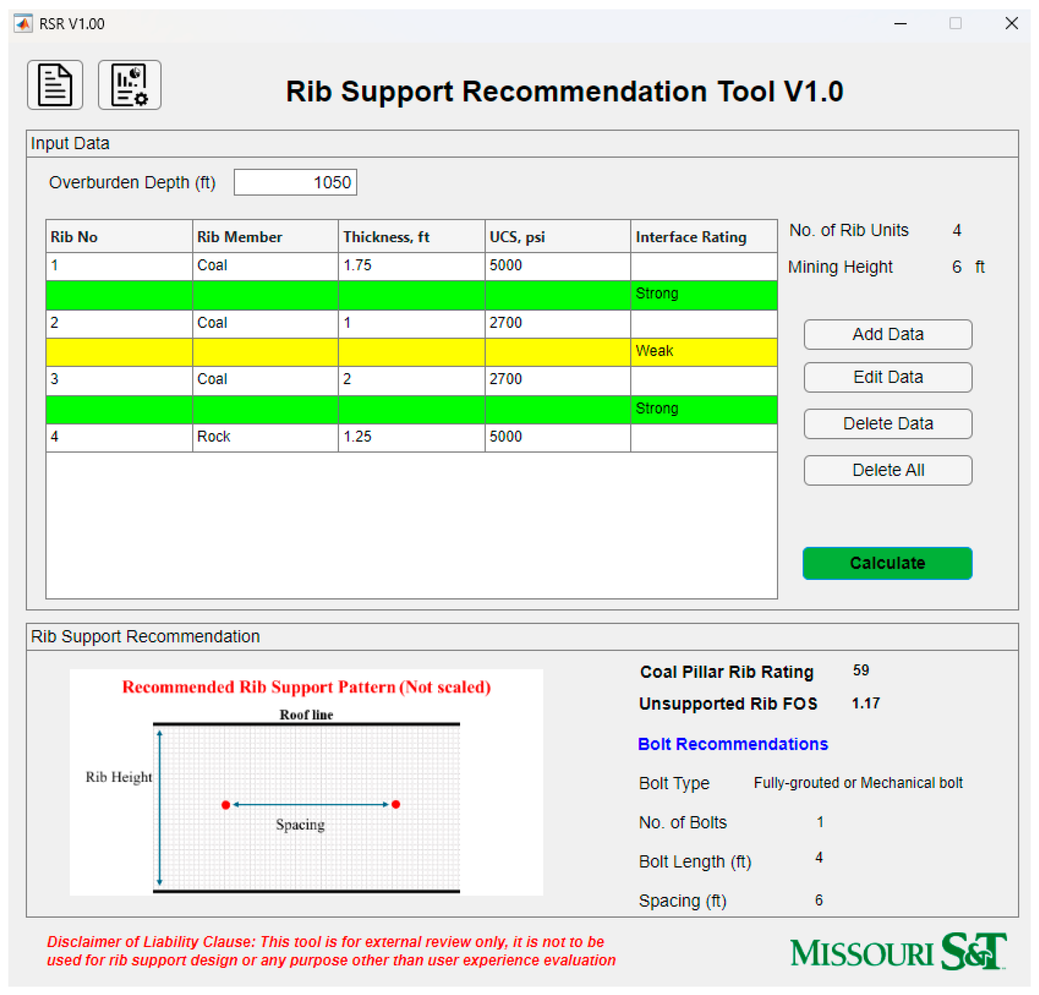
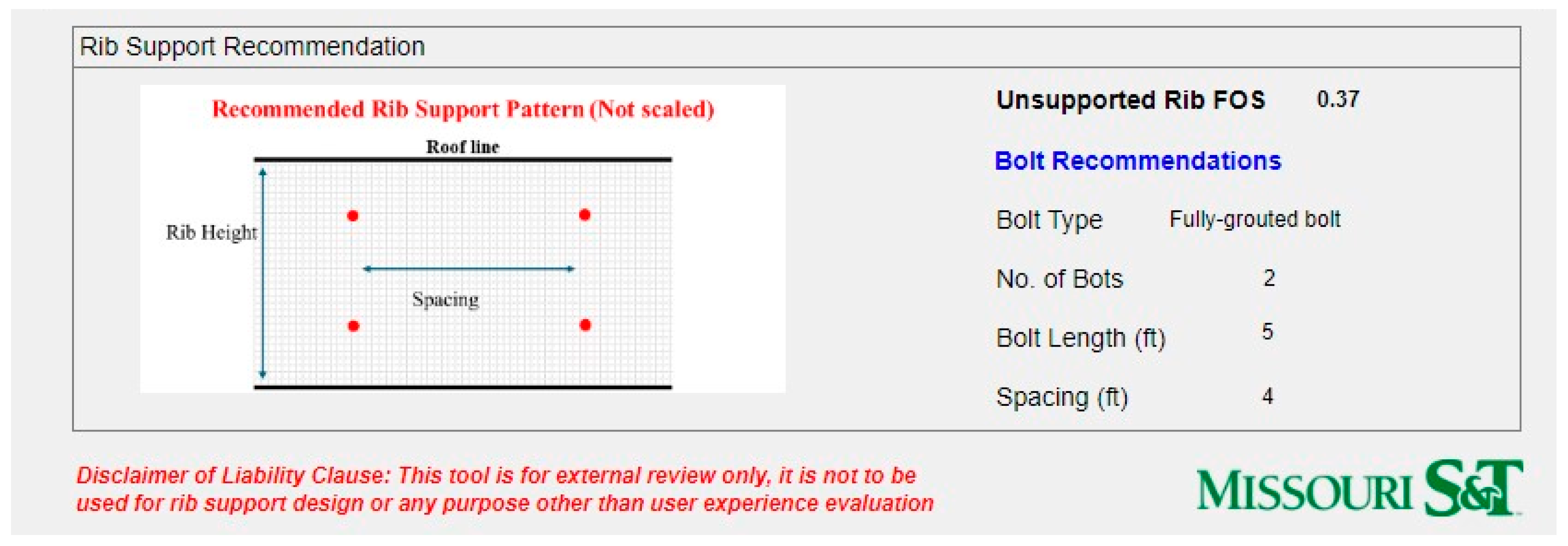
| Estimated CPRR: 36 | Estimated CPRR: 61 | ||||||
| Estimated Unsupported RibFOS: 0.37 | Estimated Unsupported RibFOS: 1.24 | ||||||
| Recommended Support Class: 4. B | Recommended Support Class: 4. G | ||||||
Disclaimer/Publisher’s Note: The statements, opinions and data contained in all publications are solely those of the individual author(s) and contributor(s) and not of MDPI and/or the editor(s). MDPI and/or the editor(s) disclaim responsibility for any injury to people or property resulting from any ideas, methods, instructions or products referred to in the content. |
© 2025 by the authors. Licensee MDPI, Basel, Switzerland. This article is an open access article distributed under the terms and conditions of the Creative Commons Attribution (CC BY) license (https://creativecommons.org/licenses/by/4.0/).
Share and Cite
Kirmaci, A.; Wijesinghe, D.R.; Guner, D.; Karadeniz, K.E.; Mitchell, C.; Sherizadeh, T. Enhancing Safety in U.S. Coal Mines Through a Rib Support Recommendation Tool. Geosciences 2025, 15, 17. https://doi.org/10.3390/geosciences15010017
Kirmaci A, Wijesinghe DR, Guner D, Karadeniz KE, Mitchell C, Sherizadeh T. Enhancing Safety in U.S. Coal Mines Through a Rib Support Recommendation Tool. Geosciences. 2025; 15(1):17. https://doi.org/10.3390/geosciences15010017
Chicago/Turabian StyleKirmaci, Alper, Dakshith Ruvin Wijesinghe, Dogukan Guner, Kutay E. Karadeniz, Cameron Mitchell, and Taghi Sherizadeh. 2025. "Enhancing Safety in U.S. Coal Mines Through a Rib Support Recommendation Tool" Geosciences 15, no. 1: 17. https://doi.org/10.3390/geosciences15010017
APA StyleKirmaci, A., Wijesinghe, D. R., Guner, D., Karadeniz, K. E., Mitchell, C., & Sherizadeh, T. (2025). Enhancing Safety in U.S. Coal Mines Through a Rib Support Recommendation Tool. Geosciences, 15(1), 17. https://doi.org/10.3390/geosciences15010017