Article

Mechanical Influence of Inherited Folds in Thrust Development: A Case Study from the Variscan Fold-and-Thrust Belt in SW Sardinia (Italy)

Department of Chemical and Geological Sciences, University of Cagliari, Cittadella Universitaria-S.S. 554 bivio per Sestu, 09042 Monserrato, CA, Italy
*
Author to whom correspondence should be addressed.
Geosciences 2021, 11(7), 276; https://doi.org/10.3390/geosciences11070276
Submission received: 10 April 2021 / Revised: 7 June 2021 / Accepted: 28 June 2021 / Published: 30 June 2021

Abstract

:
Fold-and-thrust belts have a high variability of structural styles, whose investigation provides continuous updates of the predictive models that try to better approximate the geometries recognized in the field. The majority of studies are focused on the geometry and development of folds and thrust surfaces and the amount of displacement, taking into account the role played by the involved stratigraphic succession assumed as a layer cake. We present a case study from the external zone of the Variscan fold-and-thrust belt in SW Sardinia, where it was possible to investigate the lateral and vertical variations of the mechanical properties of the involved succession, how they related to previous folding, control thrust geometry, and kinematics. In this case, the superposition of two fold systems acted as a buttress that induced extensive back-thrusting. We found that there is a close connection between the attitude of the bedding and the geometry of back thrust surfaces, shear strength during thrust propagation, and variation in the shortening amount, depending on which part of the folds were cut across. The folding-related mechanical anisotropy also seems to have induced a ductile deformation in the footwall of back-thrusts. Although the case study considers the development of back-thrust, the relations between thrust and not-layer cake geometries could also be applied to fore-thrust development.

1. Introduction

Fold-and-thrust belts have been extensively studied since the second half of the last century to describe the structural style and define the mechanism of development [1,2,3,4,5,6,7,8,9,10,11]. In the last few decades, our understanding of fold-and-thrust belts has benefited from the improvement of the investigation methods, including 3D seismic surveys [12,13,14], 2D and 3D modeling and restoration software [15,16,17], tectonic geomorphology [18], and analog [19] and numerical models [20]. The relevance of the fold-and-thrust belt for research progress in crustal deformation [21], orogenic processes [22], seismic hazard [23,24,25], and hydrocarbon exploration [26,27,28] has led to increasing interest from both academics and industry in recent years, and to the publication of several Special Issues and review papers that address this topic for different purposes and through varying approaches [29,30,31,32,33,34,35,36]. A huge number of published papers highlight the high variability of structural styles and features that characterize the fold-and-thrust belts worldwide, both active and fossil. Differences may arise because of different geodynamic settings where the fold-and-thrust belts develop, namely, collisional [37], convergent [38], or gravity-driven [39]; depending on which part of the crust is involved, if it is thick- [40] or thin-skinned tectonics [41]; according to the rheology of the involved rocks [42,43], mechanical stratigraphy [44], the depth of the detachment [45], and the deformation rates [46]; and based on the occurrence of salt tectonics [47,48], syn-orogenic erosion and deposition [49,50] and pre-existing structures [51,52,53]. In particular, structural inheritance plays an important role because, generally, fold-and-thrust belts originate from the continental margin that was previously affected by extensional tectonics [54]. Recently, the spatial variation’s role of mechanical properties of layer-cake stratigraphy in influencing fault and fold development and linkage has been highlighted [55], but open questions remain about the influence of mechanical anisotropy related to former structures, except for the role of pre-existing normal faults [54] or fault-controlled thrust ramps [56], and how the inherited structures can be detected [34].
This paper contributes to filling these knowledge gaps, focusing on the Variscan fold-and-thrust belt of SW Sardinia (Figure 1a). The intriguing premise of this case study is the very complex tectonic evolution that the stratigraphic succession had undergone before acting as a Variscan fold-and-thrust belt. Previous studies dealing with the role of inherited structures in fold-and-thrust belts worldwide, including analog and numerical models, focus mainly on pre-existing normal faults [57,58,59,60]. Instead, in the external zone of the Variscan fold-and-thrust belt in SW Sardinia, the structural inheritance is characterized by non-layer cake stratigraphy due to the superposition of perpendicular folding events, a supposed extensional phase that occurred before the first folding event, and an angular unconformity that further complicates the mechanical stratigraphy. Due to this peculiar stratigraphic-structural setting, the study area is suitable to understand how the geometry, kinematics, and dynamics of thrust faults may be influenced by inherited folds that produced a litho-stratigraphic heterogeneity. Interestingly, the resulting structural style of the Variscan fold-and-thrust belt in SW Sardinia is strongly marked by extensive back-thrust development (Figure 1b,c). Although these structures have been recognized in Sardinia for a long time [61,62,63,64], there is still a lack of detailed studies on their geometry, kinematic, and mechanical features.
In this paper, we present geological and structural data and the reconstruction of the geometry, kinematics, and displacement of the back-thrusts that unravel what relationships exist between the structural style of the fold-and-thrust belt and the structural inheritance. The majority of the speculations about the influence of complex structures on the mechanics of thrusting can also be extended to fore-thrusts.
Our conclusions illustrate what happens when a poly-deformed faulted and folded stratigraphic succession is involved in a fold-and-thrust belt, and how a complex structural inheritance may influence the distribution, geometry, kinematics, and dynamics of the structures.

2. Data and Methodology

This study is based on field investigation and structural analysis, whose starting point is the recent geological map at 1:50,000 scale “Foglio 555 Iglesias” performed by the Italian Geological Survey (ISPRA Carg Project; [64]). Field investigation were carried out to detail the main stratigraphic and tectonic contacts—orientation of beds, folds and faults elements, and kinematic indicators—and report them on a topographic map at 1:10,000 scale, thus reducing in this way the uncertainty of the data analysis due to the scale dimension.
The 3D geometry of stratigraphic and tectonic contacts has been reconstructed by means of handmade structural contours derived by their intersections with topographic contours at 1:10,000 scale with a 10 m contour-lines interval (Figure 2). The iterative procedure of detailed mapping, field observations, and structural contouring, to estimate the consistency between outcrop data and structure contouring, provided a further validation of the geological map reducing inconsistency that can arise from data errors and contouring artifacts [65]. A further control of the quality of the structural contouring has been performed following the procedure proposed by Tearpock and Bische (2002) [66].
From the contour map, the main geometric characteristics of the back-thrust were extracted: the length, measured tip-to-tip parallel to the average strike (fault length sensu [67]), and the dip and dip direction, measured as average along the reconstructed fault plane. In particular, the length of the back-thrusts has to be considered as the minimum, certain value because it refers to where the back-thrusts have been effectively detected, taking into account that the length may be longer if the back-thrusts are hidden by Quaternary deposits, mine dumps, or highly wooded areas.
The footwall and hanging wall cutoff lines of the significative stratigraphic contacts have been reconstructed. Note that they are often curved lines since the faults cut folded surfaces; moreover, the same contact could produce not parallel cutoff lines in the footwall and in the hanging wall since the fault can cut the same fold in different part (i.e., limb or hinge) (Figure 2). The cutoff lines have been employed to calculate the displacement; given that sometimes they are not parallel, an average distance was take into account and the results have been approximated to decameters. The horizontal (H), vertical (V), and net (N) displacement along the back-thrusts has been calculated following these steps: (1) H was measured parallel to the transport direction between the cutoff lines of the same stratigraphic contact in the hanging wall and footwall; (2) the steepness of the back-thrust was calculated parallel to the transport direction; (3) V and N were calculated using the values obtained from (1) and (2) by means of trigonometric functions. Note that H and V coincide to heave and throw only in the case the transport direction is parallel to the dip direction of the back-thrust.
The geological cross-sections have been made from the structural contour maps at 1:10,000 scale, honoring all the field data. Considering that the study area suffered at least three different shortening directions, 2D cross-section balancing was not allowed. The non-cylindricity of the structures along the cross-section—which prevent a restoring and balancing procedure—is highlighted by some sudden changes of the apparent thickness of the same formations. It happens because along the same geological cross section a fold is cut along both the hinge zone—so the true thickness is projected onto the cross-section —and along the vertical limb—so an apparent, larger thickness is projected.
Move Suite by Petroleum Experts (Petex) Ltd. (Edinburgh, UK) was used to draw and restore some faults starting from the handmade structural contour lines, and to build the “Allan diagrams” [65,68], which allowed us to recognize the displacement of the different stratigraphic contacts along the same fault.

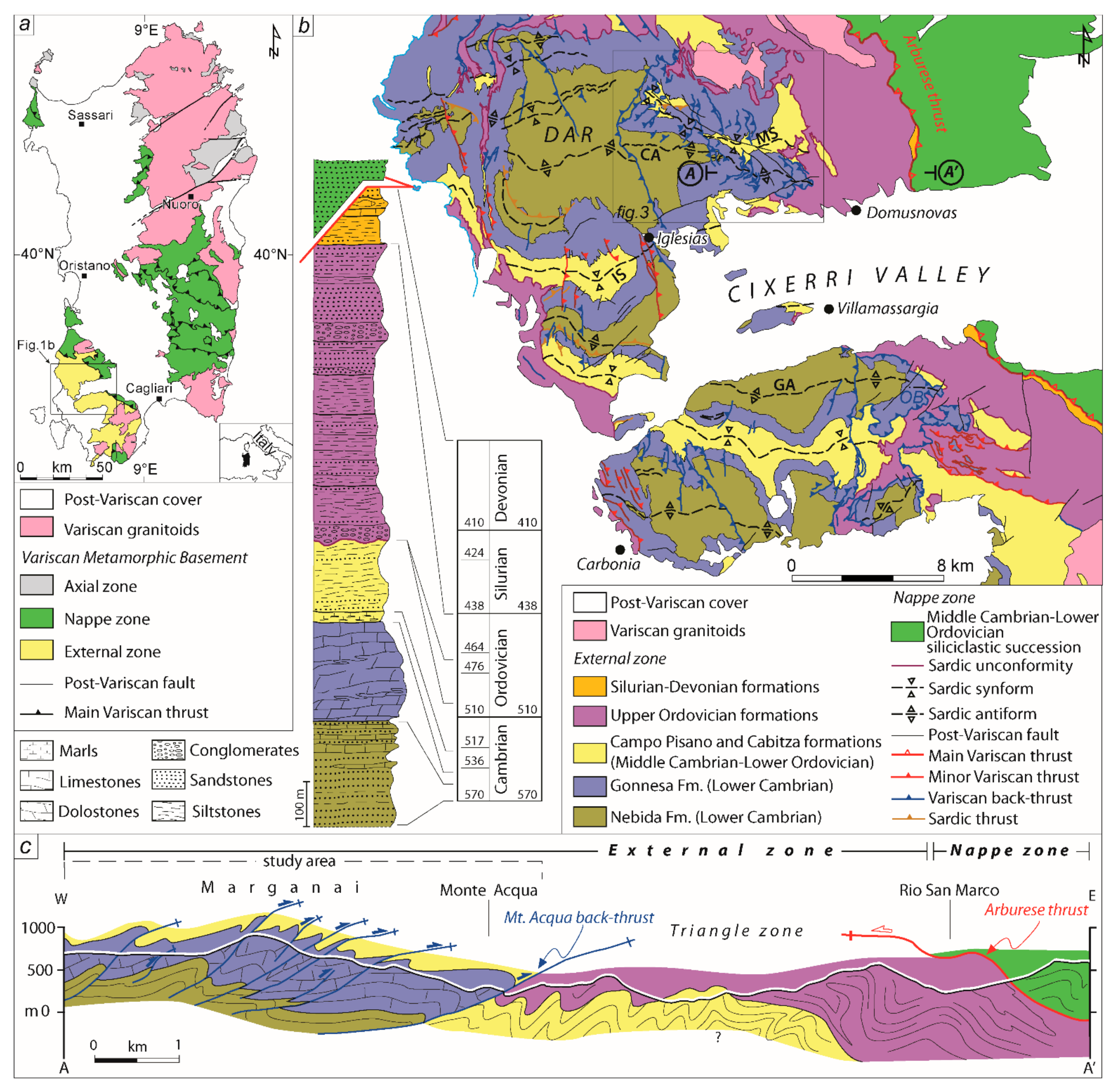
3. Geological Background

The Paleozoic basement of Sardinia is an almost complete segment of the Variscan chain where the axial, nappe, and external zones of the orogenic belt are well exposed (Figure 1a). The structure of the Variscan chain in Sardinia resulted from a N–S shortening (in present-day coordinates) related to the continental collision that occurred in early Carboniferous times [69]. The nappes were emplaced at first with a top-to-the-S transport direction and later with a top-to-the-W [70]. The W-directed tectonics gave rise to the emplacement of the nappe zone over the external zone [63]. The Arburese thrust (Figure 1b,c) that separates the nappe zone and the underlying external zone is the main Variscan structure cropping out in SW Sardinia. It strikes NW–SE, dipping to NE, for more than 60 km and is marked by a 50 m thick shear zone [63,71].
The external zone stratigraphic succession involved in the Variscan deformation spans in age from the lower Cambrian to the lower Carboniferous [72]. From the bottom to the top, the stratigraphic succession is composed of the following formations (Figure 1b), of which a brief description is given. The Nebida Fm. (lower Cambrian) consists of more than 500 m thick alternating sandstones and siltstone with episodic carbonate intercalations and characterized by a continuous oolithic limestone level [73]. The Gonnesa Fm. (lower Cambrian) shows a change in the sedimentological conditions and is made up of well-stratified dolostones and massive limestones up to 500 m thick [74]. The Campo Pisano Fm. (middle Cambrian) is a 20 to 50 m thick succession of marly limestones that mark the transition to the overlying Cabitza Fm. (middle Cambrian-Lower Ordovician), a 400 m thick alternation of levels of claystones, siltstones, and fine-grained sandstones [75]. During the Lower-Middle Ordovician there is a stratigraphic gap marked by an angular unconformity (Sardic Unconformity, [76]) related to the Sardic Phase [77], a regional tectonic event affecting the northwestern margin of Gondwana [78,79,80,81]. The Sardic unconformity is covered by the Monte Argentu Fm. (Upper Ordovician), a siliciclastic succession, which ranges from a few tens of meters to 600 m thick, characterized at the base by olistoliths, megabreccias, and coarse conglomerates that evolve up-section to marine sandstones and siltstones [82]. Above the Monte Argentu Fm., deposition of siliciclastic sediments persisted throughout the entire Upper Ordovician [83] passing successively to black-shales and limestones Silurian-Middle Devonian in age [84]. Finally, the lower Carboniferous clastic deposits [85] caps the stratigraphic succession.
Some rough observations on the mechanical properties of the lithostratigraphic succession can be made considering the structural style of the different units involved in the same deformational event. A first-order mechanical discontinuity is between the Gonnesa and the Campo Pisano fms. The limestones and dolostones of the Gonnesa Fm. are generally deformed in large wavelength (up to 1000 m) buckled folds with m-size minor order structures and a spaced axial-plane cleavage. The marlstones, fine-grained sandstones, and shale of the Campo Pisano and Cabitza fms are deformed in buckled folds with thickened hinges, a well-developed axial plane cleavage and an average wavelength less of 100 m to dm in size. Therefore, the Gonnesa Fm. looks to have had a higher shear strength than that of the Campo Pisano and Cabitza fms. Indeed, some back-thrusts developed along the contact between Gonnesa and Campo Pisano fms. Other mechanical discontinuities, of minor order, can be recognized, e.g.: the contact between the coarse conglomerates and breccias at the base of the M. Argentu Fm. and the fine sandstones and shale of the Cabitza Fm.
In the external zone three tectonic phases are recognized, which gave rise to a very complicated structural setting: the first event is related to the middle Ordovician Sardic phase, and the second and third to the Variscan event.
The Sardic Phase was a compressional event that involved only the stratigraphic succession beneath the Sardic unconformity. According to the N–S shortening direction, E-trending folds developed, geometrically characterized by upright axial surface, close tightness, and a kilometric wavelength; no tectonic foliation is clearly associated with this folding event. Axes plunge towards the E and the W according to the effect of the later folding, so these folds are not cylindrical, e.g., the Malacalzetta Synform (Figure 3). The steep limbs of the Sardic folds are cut at a high angle by the Sardic unconformity, sometimes approaching 90°. The kilometric map-scale Sardic folds are peculiar features of the structural setting of the external zone. Moving from north to south, they are (Figure 1b): the Malacalzetta Synform, the Cuccuru Contu Antiform, the Iglesias Synform, and the Gonnesa Antiform. Along with the folds, Sardic reverse faults striking roughly E–W have been also detected [64,86].
The Variscan deformation affects the entire stratigraphic succession from the lower Cambrian to the lower Carboniferous and it is postdated by upper Carboniferous continental succession [64]. The I Variscan Phase, is characterized by folds trending E–W that are superposed on the Sardic folds, with the same shortening direction [61], forming a type 0 interference pattern (according to [87]). The axial surfaces are upright, and the tightness is open, so that the Sardic unconformity and the stratigraphic succession above it are gently deformed, whereas the Sardic folds are slightly more shortened.
The II Variscan Phase differs from the previous in the E–W shortening direction, which is perpendicular to the shortening related to both Sardic and I Variscan phases. The II Variscan Phase accumulated the highest shortening throughout a progressive deformation that gave rise, sequentially, to N-trending folds, W-verging fore-thrusts, and, finally, E-verging back-thrusts [61,62,63] that gave rise, along with the Arburese thrust, to a triangle zone [63] (Figure 1c). The N-trending folds are characterized by N-trending axes whose dip changes according to the position of the layers already folded by the previous folding events. Axial surfaces are generally upright, sometimes steeply dipping towards the W (Figure 4), the first-order wavelength is of a few hundred meters with associated minor order folds. The stretching lineation related to this tectonic phase always trends E-W.
The superposition of two perpendicular fold systems striking roughly E–W and N–S formed a type 1 interference pattern [87], whose main map-scale structure in the study area is the so-called “Arenarie Dome” (“Arenarie”, which means sandstones, is the older name of the Nebida Fm.), a dome consisting of sandstones belonging to the Nebida Fm. surrounded by the dolostones and limestones of the Gonnesa Fm. (Figure 1b). Due to the N-trending Variscan folds, the E-trending folds show a cartographically clear change in the axes plunging direction from W-ward to E-ward. In addition to this, the steep limbs of the Sardic folds are deformed by N-trending folds with steep axes plunging either N-ward or S-ward according to the attitude of the limb they affect. Following this, the dome-and-basin structure is involved in the fore- and back-thrusts development. Among the most noticeable at map-scale, are the fore-thrusts that cut across the Iglesias Synform and the Gonnesa Antiform and the back-thrust that displaces the core of the “Arenarie Dome” (Figure 1b). It is worthy to underline this change in structural style in the zone close to the nappe front: back-thrusts and fore-thrusts are widespread close to the Arenarie dome and to the Iglesias Synform, respectively. In the following, given that in the study area generally just the pre-Sardic succession are involved in back-thrusting, we will refer to the E-trending fold as Sardic, considering that is not possible to easily distinguish the effect of the superimposed I Variscan E-trending folding. However, because the Sardic unconformity reaches up to 90° and E-W-trending upright limbs lack in the post-Sardic succession, we consider the E-trending folds Sardic rather than Variscan.

4. Results

The study area (Figure 3) is located in the northern sector of the external zone between the “Arenarie Dome” and the leading edge of the nappe zone, where the back-thrusts extensively crop out. In this sector, the exposed formations are progressively younger moving towards the nappe front, because of erosion processes and according to the interference pattern of superposed perpendicular folding. Here, the stratigraphic succession spans in age from lower Cambrian to Silurian. In roughly the same way, there is an increasing mechanical weakness of the lithologies moving towards the nappe front: the sandstones of the Nebida Fm., the limestones and dolostones of the Gonnesa Fm., the marly limestones of the Campo Pisano Fm., the fine sandstones, pelites and siltstones of the Cabitza Fm., the conglomerates, phyllites and shales of the upper Ordovician-Silurian succession, this last lying just below the Arburese thrust (Figure 1). However, this seemingly simple mechanical stratigraphy is structurally complicated by the occurrence of the Sardic and Variscan antiforms and synforms. The back-thrusts mainly affect the pre-Sardic Unconformity succession, crosscut the Sardic folds, and are rare in the post-Sardic unconformity succession. Additionally, there is not any information about the occurrence of a basal detachment.
In the following paragraphs, based on a 3D reconstruction through structural contour lines of the stratigraphic and tectonic surfaces and on analyses of fault rocks and kinematic indicators on thrust’s surface, we describe the main outcrop- and map-scale characteristics of the back-thrusts, the relationships between the back-thrusts surfaces and the attitude of the underlying folded strata in their footwall, and the folds that affect the Variscan S1 cleavage in the footwall of some back-thrusts.

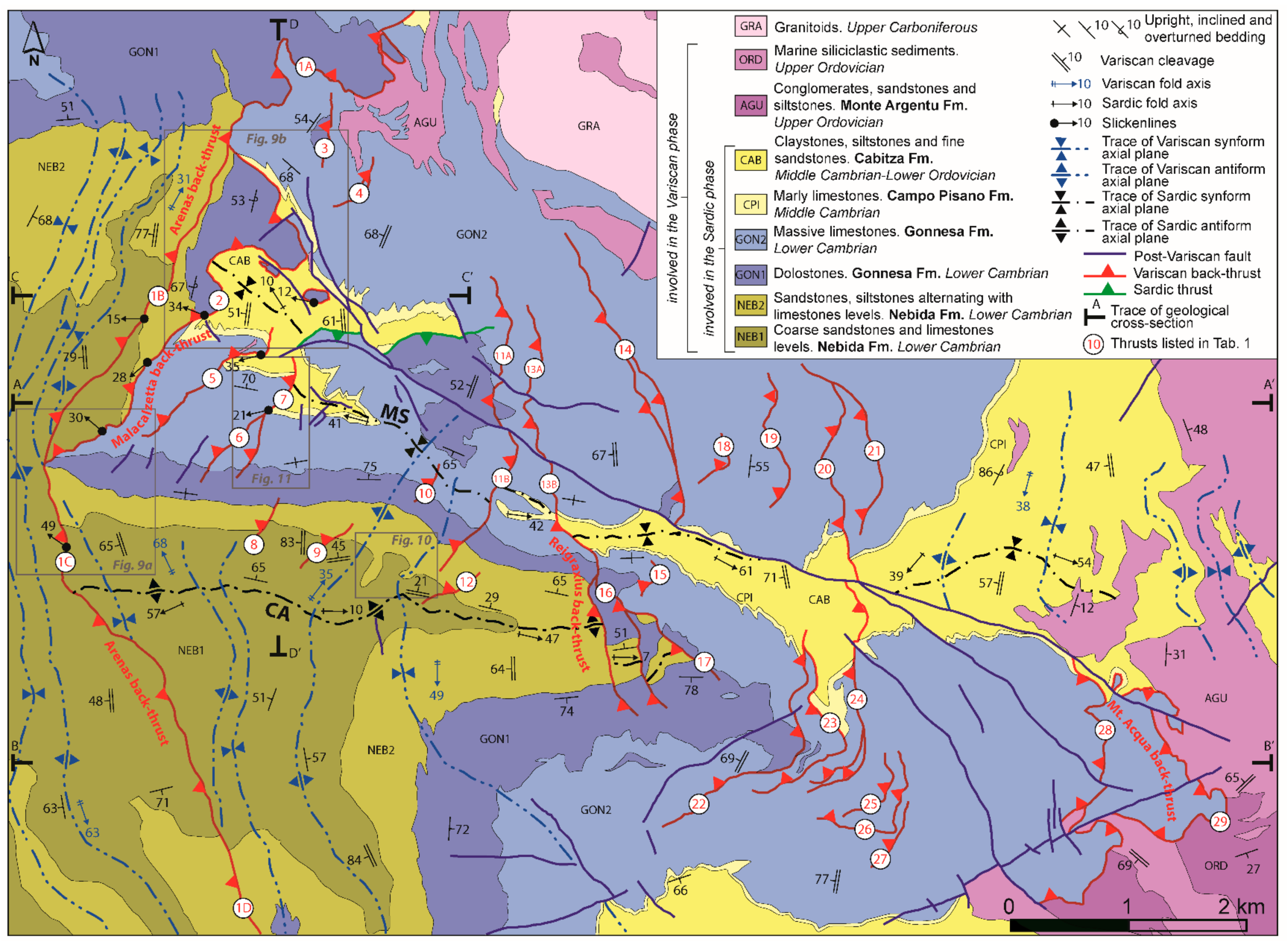
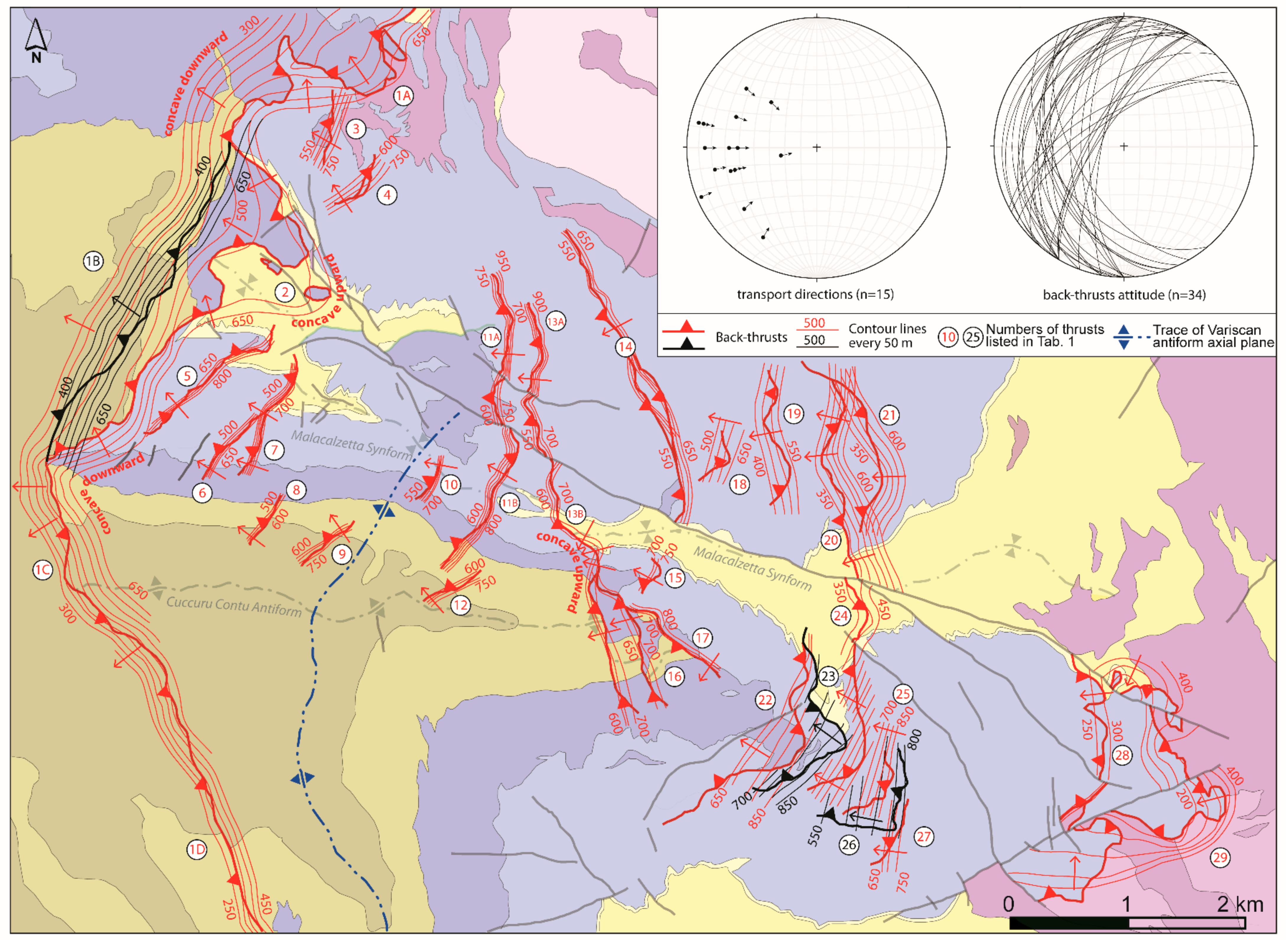
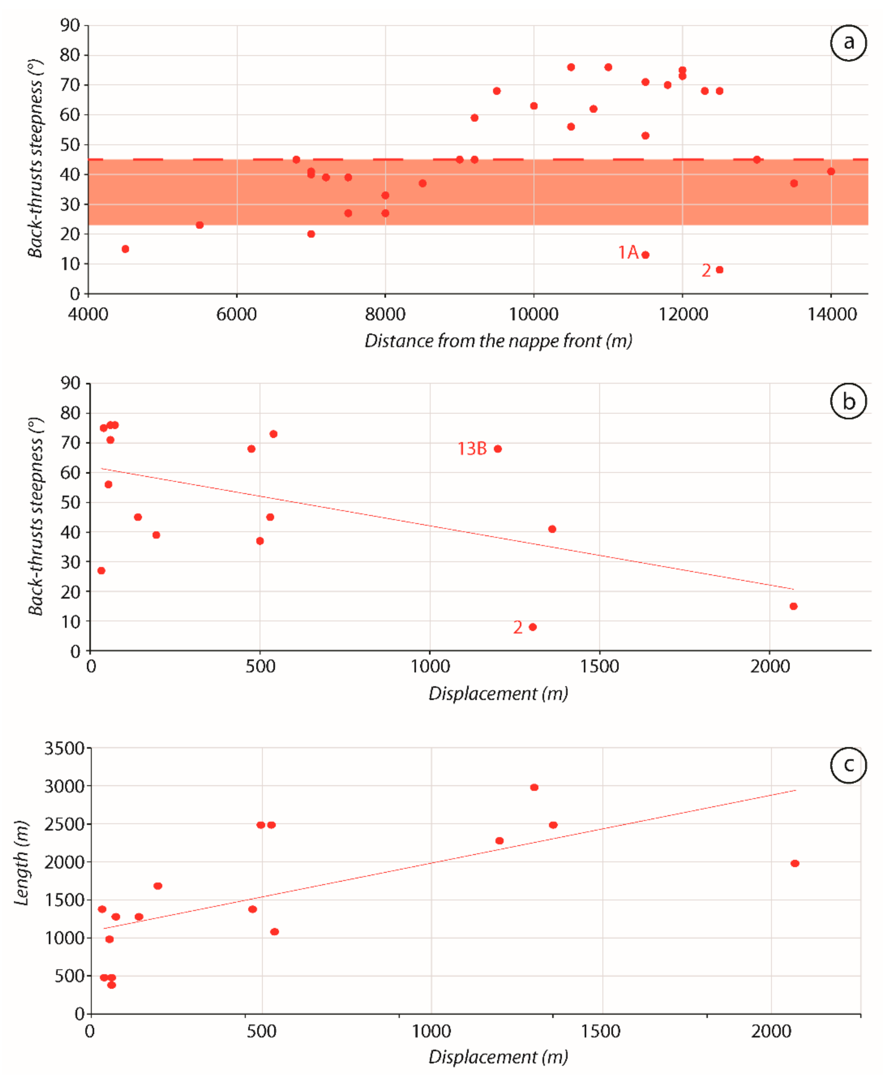
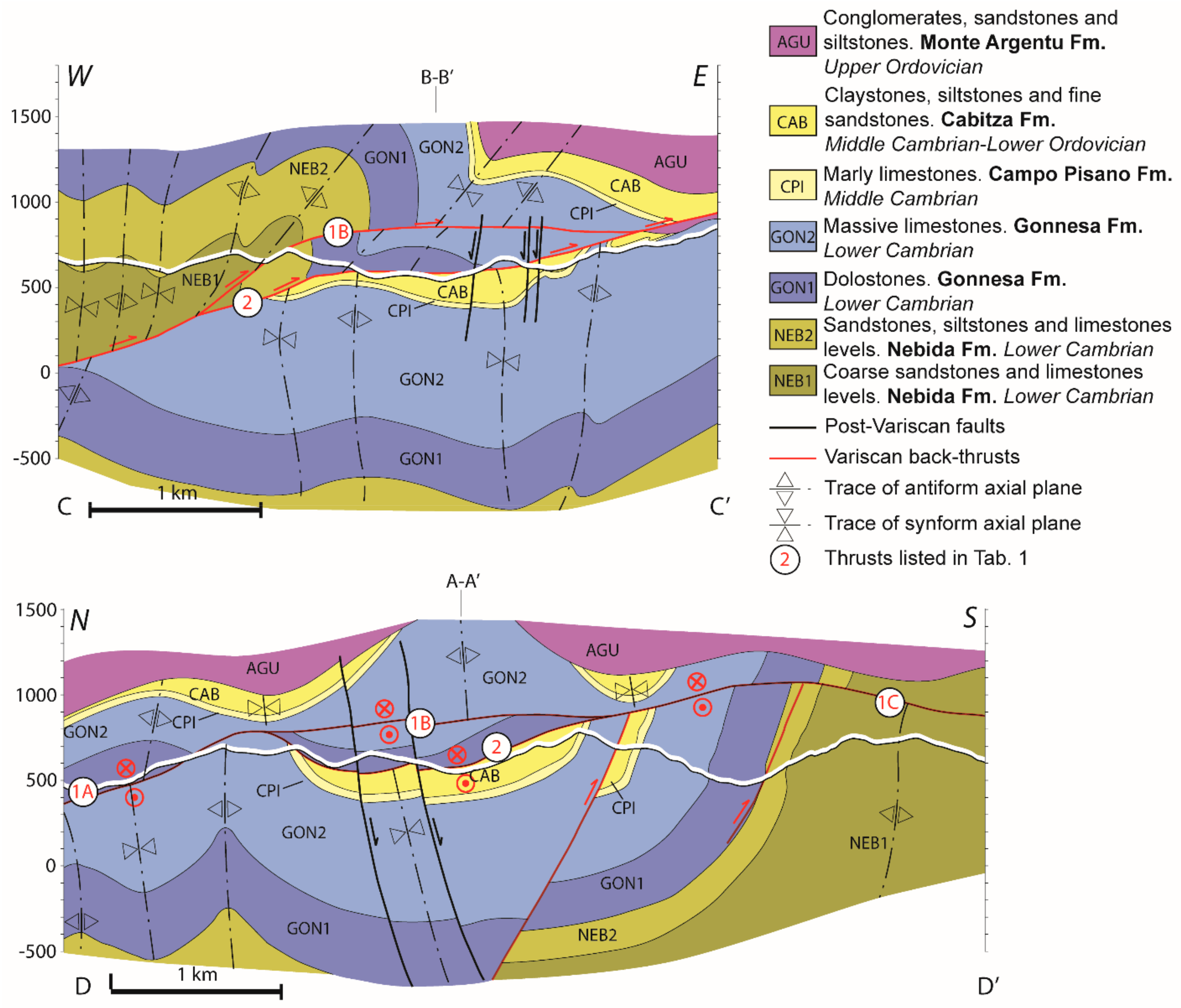
4.1. The Back-Thrusts of the Marganai Area

In the field, the back-thrusts are recognizable in landscape view if they give rise to a rugged morphology, for example, when the limestones of the Gonnesa Fm. overthrust on the shales of the Cabitza Fm. (Figure 5a). At the outcrop scale, the back-thrusts are marked by a 1 to 10 m thick shear zone characterized by the occurrence of a different type of fault rocks depending on the lithologies affected. When the back-thrusts affected the sandstones of the Nebida Fm., a fault gouge (Figure 5b) or foliated cataclasite (Figure 5c) developed. The fault gouge may be either several meters thick or be confined between discrete slickenside in fault cores that are a few decimeters thick. The foliated cataclasite developed in bands with a thickness of a few meters and are characterized by fish-shaped fragments (Figure 5c1), are a few decimeters long, and are bounded by slickensides that sometimes show slickenlines (Figure 5c2). When the back-thrusts affected the limestones and dolostones of the Gonnesa Fm. the fault rocks may be either breccias or calcite-mylonite. The breccias consist of millimetric to centimetric angular fragments glued by an intergranular calcite cement (Figure 5d). The calcite–mylonite is characterized by alternating black and white millimetric layers that are parallel to the mylonitic foliation. In the marly limestones of the Campo Pisano Fm. and in the fine sandstones and shales of the Cabitza Fm., mylonite developed more commonly (Figure 5d). The mylonite zones are several meters thick and include different kinds of kinematic indicators. At the outcrop-scale, asymmetric folds (Figure 5e), S–C fabric (Figure 5f) and foliation deflection (Figure 5g) indicate a top-to-the-E shear sense. In thin sections, parallel to the aggregate lineation and perpendicular to the foliation, the shear sense can be accurately defined by asymmetric porphyroclasts (Figure 5h,i), sigmoids, and domino and shear bands boudins that consistently indicate a top-to-the-E transport direction (stereographic projection in Figure 6). The same kinematic indicators are recognized in the calcite-mylonite along the Orbai back-thrust [63]. Rarely, an opposite shear sense has even been detected, as commonly observed in mylonitic shear zones [88,89].
The detected back-thrusts show remarkable differences from each other for what concerns their length and attitude. The length varies a lot, from a few hundred meters to several kilometers (Figure 3 and Figure 6, Table 1). The dip direction ranges between N230 and N330 and the dip is also highly variable, between 8° and 76° (Figure 4, stereographic projection in Figure 6, Table 1).
The Arenas back-thrust (1 in Figure 3 and Figure 6) exhibits the greater along-strike length, more than 9 km, striking from the Arenas mine to the village of Iglesias. The longest back-thrusts, the Arenas and Reigraxius back-thrusts (1 and 13 in Figure 3 and Figure 6), crosscut the entire lower Cambrian-Upper Ordovician succession and involve both hinges and limbs of the Sardic folds. Other back-thrusts are shorter, reaching a few kilometers or only a few hundred meters in length (e.g., 6, 10, 19, and 21 in Figure 3 and Figure 6, Table 1), the shortest ones developed alternatively in the hinges or limbs of the Sardic folds, therefore involving only a portion of the stratigraphic succession. Indeed, some back-thrusts affected only the Gonnesa Fm. (e.g., 3, 4, 18, and 27) or the Nebida Fm. (e.g., 9 and 12).
The steepness changes along the same back-thrust according to a ramp-and-flat geometry, where the layer’s competence decreases up-section. The back-thrust’s dip changes from 40° to 45° within the sandstones of the Nebida Fm. and the limestones and dolostones of the Gonnesa Fm. (1C and 1D) to 13° where the lower Cambrian succession is thrusted over the conglomerates, phyllites, and shales of the Monte Argentu Fm. near the Arenas mine (1A). Similarly, the Mt. Acqua back-thrust (29) is steep at 15° where it thrusts the limestones of the Gonnesa Fm. over the Upper Ordovician succession (Figure 4, Figure 6).
However, the steepness is also highly variable among back-thrusts that affect the same lithology, in particular for those within the Gonnesa Fm. These back-thrusts become less steep, from more than 70° to 20° (Figure 4 and Figure 6, Table 1), moving from the western to the eastern sectors of the study area, that is, approaching the nappe front. In general, this trend is shared by all the back-thrusts in the study area (Figure 7a). About 50% of the back-thrusts detected show a steepness lower than 45° (Figure 7a), which are values generally observed in fore-thrusts (e.g., [6]), whereas back-thrust should be steeper [90]. The out-of-trend dip of the back-thrust 1A and 2 in Figure 7a is related to the weak mechanical properties of the lithostratigraphic units they overthrust, that is the Monte Argentu and Cabitza fms, respectively.
A total displacement of more than 7.5 km has been measured in the study area, with the bulk of shortening accommodated by four main back-thrusts, namely Arenas, Malacalzetta, Reigraxius, and Mt. Acqua back-thrusts (respectively: 1, 2, 13, and 29 in Figure 3 and Figure 6), and a small amount of shortening distributed among other back-thrusts that accumulated displacements lower than 500 m. In general, the displacement varies according to the back-thrusts’ dip and length (Figure 7b,c): the steeper the back-thrusts the lower the displacements, although few exceptions occur. For example, back-thrusts 2 and 13 show comparable displacements despite a difference of 60° in dip (Figure 7b, Table 1). The back-thrusts several kilometers long exceed a displacement of 1000 m, those more than 1000 m long reach a displacement of a few hundred meters, and those more than 100 m long accumulate only a few decameters of displacement (Figure 7c, Table 1). These values are consistent with the displacement/length ratio inferred by several datasets (e.g., [67]). The Mt. Acqua back-thrust (29 in Figure 3, Figure 4 and Figure 6, Table 1) accumulated at least 2 km of displacement, the highest in the area, but it may be much larger considering that it has been measured in the map as the minimum. Even the length of the Mt. Acqua back-thrust is larger than the 2 km inferred from the map, as suggested by the displacement/length ratio that arises from it. The Mt. Acqua back-thrust may be reasonably correlated to the Orbai back-thrust (Figure 1b) that crops out less than 10 km southward, south of the Cixerri valley, now separated from an open synform filled by Cenozoic deposits [91], because they affect the same formations and are both the closest to the nappe front. The Orbai back-thrust should be 15 km long and should have accommodated a minimum displacement of 7 km [63]. Along the Arenas back-thrust, the displacement increases from the tip (1D in Figure 3), near Iglesias town, to San Benedetto village, where it exceeds 1300 m (1C in Figure 3). Further to the north, a tectonic sliver bounded at the top by the Arenas back-thrust and at the bottom by the Malacalzetta back-thrust (2 in Figure 3 and Figure 8) occurs. Here, the Arenas back-thrust accumulated a net displacement of 500 m and the Malacalzetta back-thrust a minimum displacement of 1300 m (Table 1). Then, the total shortening accommodated in this area exceeded 1800 m. Even the Reigraxius back-thrust (13 in Figure 3) crosscut the Sardic folds, involving the Campo Pisano and Cabitza fms in the hinge of the Malacalzetta Synform and the Nebida and Gonnesa fms in the hinge of the Cuccuru Contu Antiform (Figure 3 and Figure 6). The displacement evaluated reaches 1200 m in the Campo Pisano and Cabitza fms and a few hundred meters in the Nebida and Gonnesa fms. Interestingly, the Reigraxius back-thrust accumulated a higher displacement in the younger than in the older succession. This occurrence is not unique and typifies other back-thrusts, and it will be discussed in the Section 5.2.

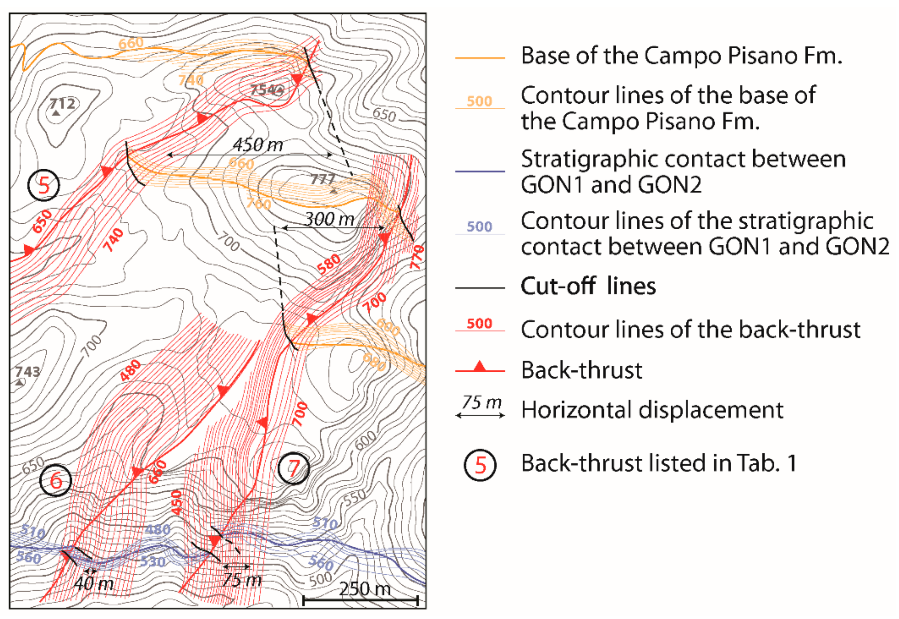
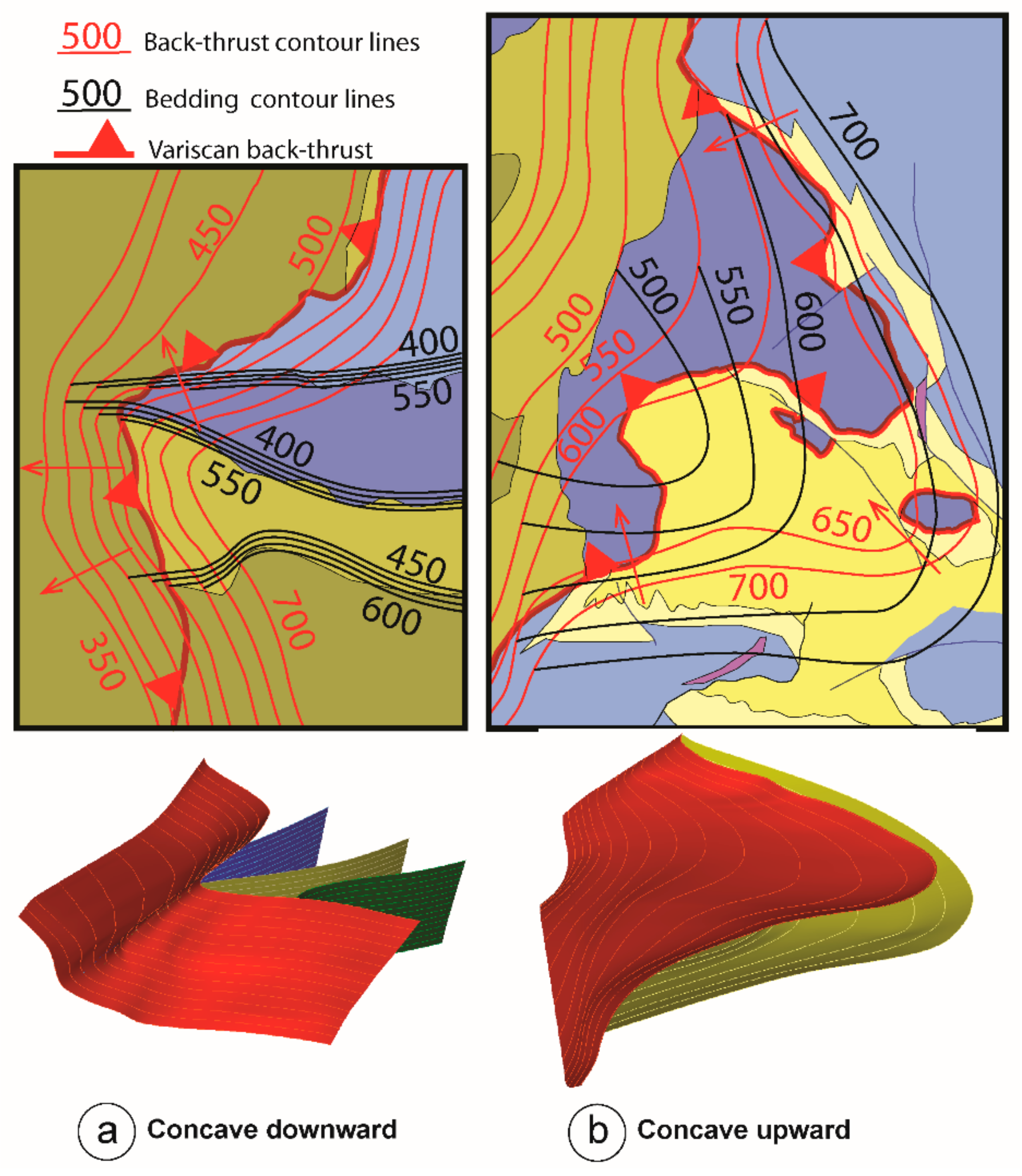
4.2. Relationships between Inherited Folds and Three-Dimensional Geometry of Back-Thrusts

The primary Variscan structural feature in the study area is the type I interference pattern between the later N-trending and the earlier E-trending folds (namely, the Sardic folds that only affect the Cambrian-Lower Ordovician succession) (Figure 1b). E-verging back-thrusts crosscut both the hinges and limbs of these map-scale folds (Figure 3 and Figure 4), but their development looks particularly influenced by the E-trending Sardic folds. Interestingly enough, depending on which part of the Sardic folds is affected, limb or hinge, the back-thrusts are characterized by a variation in dip direction, steepness and shape, i.e., concave upward or downward (Figure 8) considered as a change in dip along their general strike, thus resembling synforms or antiforms with roughly E-trending axis (Figure 6), not to be confused with the change in steepness along the dip of ramp and flat geometry. In the follows we will use the terms concave and avoid as much as possible the term antiform and synform because we interpret these shapes as acquired during the back-thrust emplacement and not as the result of a shortening.
Considering the relationships between back-thrusts and the plunging direction of the E-trending folds hinges, two structural domains delimited by the axial trace of a N-trending Variscan antiform (Figure 6) can be identified at a large scale: a western domain where the hinges of Sardic folds plunge to the west and an eastern domain where the hinges plunge to the east. Therefore, in the western domain, a 1st-order distinctive feature is that the hinges of the Sardic folds and the back-thrusts dip in the same direction, roughly to the west, whereas in the eastern domain they have opposite dip directions: the hinges dip to the east and the back-thrusts dip to the west. In both domains, the limbs of the Sardic folds reach a sub-vertical attitude, perpendicular to the strike of the back-thrusts. These two domains can be further subdivided in 2nd order domains related into 2nd order N-trending axial planes.
The back-thrusts are concave downward (Figure 9a), assuming the shape of an antiform, where perpendicular, sub-vertical limbs are cut across. The geometry of these antiforms show evident relationships with the attitude of the strata since the axial surface is parallel to the sub-vertical limbs and the hinge line plunges to the west (Figure 9a). Three examples in the study area are explicative of these geometric relationships: two can be observed along the Arenas back-thrust (1 in Figure 6), which takes a concave downward shape where it crosscuts the northern and southern limbs of the Malacalzetta Synform, near Baueddu and San Benedetto mines, respectively; the third along the Reigraxius back-thrust (13 in Figure 6) where it cuts across the northern limb of the Malacalzetta Synform near the Reigraxius mine.
The back-thrusts are concave upward (Figure 9b), assuming the shape of a synform, where they crosscut the hinge zone of Sardic synform that dips in the same direction. In this case, the geometry of the back-thrust is modeled laying above the overthrusted synform, reproducing the same geometry, namely, parallel axial surfaces and same axes plunging direction. The main example in the study area is given by the Malacalzetta back-thrust (2 in Figure 6) that cuts across the hinge zone of the Malacalzetta Synform (Figure 9b). Here, the Malacalzetta back-thrust assumes the shape of an open synform with a sub-horizontal hinge zone gently plunging to the west, with the axis less steep than that of the Sardic fold. Approaching the limbs of the Sardic fold, the Malacalzetta back-thrust becomes steeper, and then it is shaped concave downward as described above. Another example can be observed where the Reigraxius back-thrust (13 in Figure 6) affects the Malacalzetta Synform (Figure 6). In this case, the concave-upward shape assumed by the Reigraxius back-thrust is close and its axis is steeper than the Sardic fold axis. Note that the Reigraxius back-thrust and the Sardic synform dip in the same direction, despite being located in the eastern structural domain, which is where, on a large scale, the axes of the Sardic folds dip to the east, because of the effect of a second-order N-trending Variscan fold.
The back-thrusts surface is planar where the back-thrusts crosscut the hinge zone of inherited synforms that dip in the opposite direction of the back-thrust or the hinge zone of inherited antiforms regardless of the hinge plunging direction. Examples in the study area are the Campu Spina back-thrust (11 in Figure 4), which cuts across the E-ward plunging hinge of the Malacalzetta Synform; the Reigraxius back-thrust that cuts across the E-ward plunging hinge of the Cuccuru Contu Antiform; the Arenas back-thrust that cut across the W-ward plunging hinge of the Cuccuru Contu Antiform (Figure 3). In these cases, the back-thrusts do not show important variations in dip direction or steepness.
The inherited E-trending synforms also seem able to influence the location and size of tectonic slivers (Figure 8) as can be inferred from the tectonic sliver bounded by the Arenas and Malacalzetta back-thrusts, which, respectively, act as roof and sole thrusts. The extent of the sliver equals the distance between two adjacent inflection points of the older Sardic synform, from which the thickness of the sliver progressively increases reaching the maximum in the hinge zone of the fold. The branch lines between the roof and sole thrusts develop near the sub-vertical limbs of the inherited synform. The tectonic sliver extends for 2 km between the limbs of the Malacalzetta Synform and reached a thickness of about 300 m in the hinge zone (Figure 6 and Figure 8).

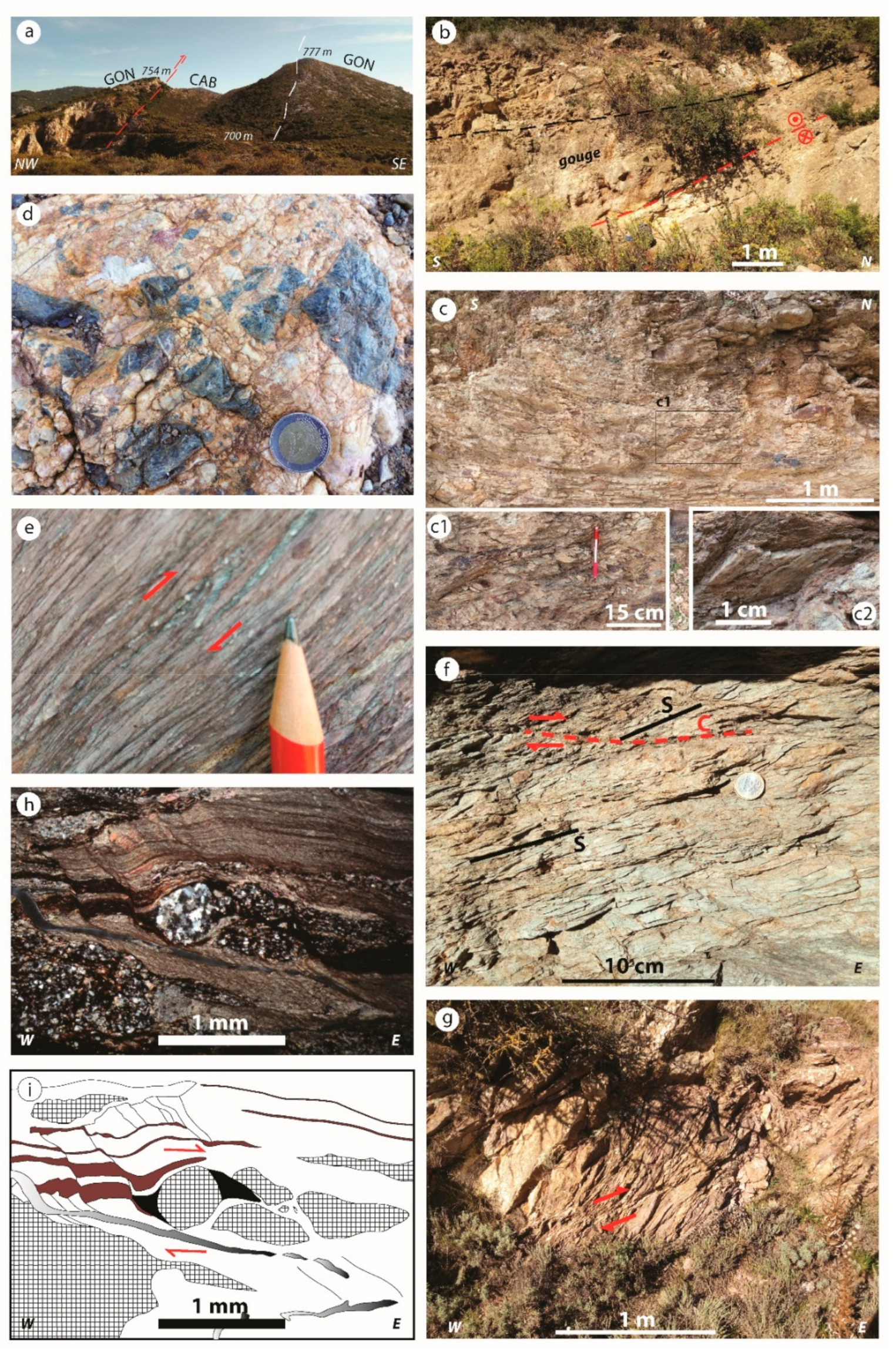
4.3. Fold Related to the Back-Thrust Emplacement

The main tectonic foliation in the study area is a cleavage (S1) related to the N-trending folds developed during the early stage of the II Variscan phase, coeval with the emplacement of the nappe zone over the external zone and predating the onset of back-thrusting. Just below the Arburese thrust the S1 dips to the E [63], whereas moving away from the nappe front it progressively assumes a vertical attitude and then steeply dips to the W [61]. However, this general attitude of the cleavage is not preserved everywhere in the footwall of back-thrusts. N-trending folds and S1 are sometimes deformed by asymmetric folds with axial plane and axis with different attitude, depending on the original attitude of the bedding, giving rise to a change in the strike direction and steepness of S1. For example, in the footwall of the Arenas back-thrust, the northern limb of the Cuccuru Contu Antiform, N-trending Variscan folds on the scale of 100s meters that affect the Nebida Fm., with well-developed S1, are refolded by folds with a WNW-plunging axis and a SW-dipping axial plane (Figure 10). A similar setting has been detected in the footwall of the Mt. Acqua back-thrust, where it overthrusts the Mt. Argentu Fm. East of the study area, close to the nappe front, in the San Marco Valley, Funedda, 2009 [63] described widespread asymmetric folds overturned to the east that deform S1 in the Upper Ordovician succession.

5. Discussion

Fore-thrusts are the typical structures that characterize fold-and-thrust belts. Back-thrusts can also occur as a consequence of different mechanisms, although they are less common than fore-thrusts [90,92,93,94,95]. Among these, the most widely accepted in collisional orogens are the following: critical taper wedge dynamics [10,96], stress accumulation on fore-thrust ramps [56,97], passive roof duplex [98,99,100], double-verging subduction [101], pop-up mechanism [102,103], variation in the weakness of the main detachment [104,105], buttressing that hinders fore-thrusting propagation [106,107], and reactivation of pre-existing faults [108,109]. All these models imply a concurrence of fore-thrusts and back-thrusts in the characterization of the structural style of the fold-and-thrust belts. In the Sardinia Variscides, back-thrusts are widespread in the external zone but not in the nappe zone; possibly it depends on the different structural level in which they developed: the external zone was deformed at the brittle-ductile transition, whereas the nappe zone in a ductile regime, and the thrusts between the different tectonic units [70] are thick ductile shear zones [71] developed together with the isoclinal, reclined folds, without a buttressing effect. Interestingly, in the area of the Variscan fold-and-thrust belt of SW Sardinia—closest to the leading edge of the nappe front—back-thrusts occur extensively without a close linkage with fore-thrust or basal detachment (Figure 3 and Figure 4), nor a deep buttressing effect, e.g., a granitoids intrusion or pre-existing normal faults that controlled thrust ramps [110,111] can be invoked. This peculiarity, together with variations in thrust geometries and amount of displacement, is hardly explainable by the analog and theoretical models proposed up to now in others fold-and-thrust belts, among them here we cited just some examples. In the Apennines chain, back-thrusting is common and generally associated to pop-up structures caused by the hampering of the layers forward displacement, not always related to the passive-roof duplexing; e.g., the Gran Sasso Range, [112] and Maiella [113]. In the Sicilian–Maghrebian fold-and-thrust belt, according to [114], a large hinterland verging displacement was allowed by a buttressing related to an irregular shape of the continental margin or to anomalous thick sedimentary sequences. Additionally, in the Southern-Central Andes (e.g., [115,116], the buttressing is produced by the impeding of foreland verging displacement caused by progressive fault-related folding. In the Cantabrian zone [117,118], which for its Variscan age, structural level, and lithology involved is very similar with the study area, the development of fore- and back-thrusting was not influenced by pre-existing folding but mainly by the mechanical anisotropy in the stratigraphy [119]. Furthermore, in the Cantabrian zone a change of structural style parallel to the fold-and-thrust belt, is reported, although not related to the occurrence of inherited folds [117].
In the following paragraphs, the role of pre-existing structures will be discussed, along with the supposed occurrence of inherited normal faults, that facilitated and influenced extensive back-thrusting development.

5.1. Influence of Inherited Dome-and-Basin Interference Pattern on Back-Thrust Development

When the Cambro-Devonian succession of SW Sardinia was involved in the Variscan fold-and-thrust belt, it underwent a top-to-the-E tectonic transport (II Variscan phase: [63,70]) that gave rise to a dome-and-basin interference pattern originated by the superposition of the N-trending folds on the older E-trending folds, followed by fore-thrusting and, finally, back-thrusting [63]. The domes-and-basins pattern, coupled with the rheology of the rocks that constitute the stratigraphic succession, played a role in the back-thrusts localization, preventing the classical ramp and flat geometries that develops when thrusting affects a layer cake stratigraphic succession and the genesis of the related fault-bend folds. The lithologies are weaker in the upper part of the succession, so that the core of domes, made up of sandstones and limestones, is more competent than the core of the basins, mainly made up of fine sandstones and shales. Thus, the dome structures had a buttressing effect inhibiting the foreland-ward propagation of the deformation, whereas the basin structures did not. As a consequence, the domes (e.g., Arenaria Dome in Figure 1b) favored the development of hinterland-verging structures whereas the basins (e.g., Iglesias Synform in Figure 1b) favored the development of foreland-verging structures. Therefore, unlike previous description (see Alsop et al., 2017 [120], for an extensive summary), where the buttressing is related to the accumulation of deformation in front of fore-thrust, in the study area the buttressing pre-existed. This hypothesis is corroborated by the widespread back-thrust development between the first-order dome-structure, with a half-wavelength of about 12 km, and the nappe front (Figure 6). Therefore, from the study area arise that structural inheritance can give rise to a lateral variation of the style of fold-and-thrust belt at the upper structural levels. Additionally, in the weakest upper Ordovician succession, where no back-thrust occurred, the shortening toward the hinterland is generally accommodated by back-folds [63].

5.2. Influence of Inherited Normal Faults on Back-Thrust Development

As proposed by several Authors, including Malz et al., 2016 [109], back-thrusting may have also been facilitated by the occurrence of pre-existing normal faults. However, the occurrence of a pre-Variscan faulting event in the future Variscan external zone has been supposed by indirect observations [121], as well as their reactivation invoked [62], but they have never been detected in the field. According to Bechstadt and Boni [74], an extensional event was supposed to have occurred at the end of early Cambrian, causing the drowning and segmentation of the carbonate platform, which was successively covered by the marine marly and terrigenous sediments of the Campo Pisano and Cabitza fms during the middle Cambrian [74]. Further evidence of the activity of early Cambrian faults is the occurrence of Pb–Zn sulfide ores hosted exclusively in the lower Cambrian carbonate succession [122], based on the consideration that the process leading to this kind of ore bodies requires extensional tectonics to drive mineralizing fluids along normal faults [123]. Pb–Zn sulfides ores are aligned along some back-thrusts, for example, the back-thrusts near Genna Aragosta (5, 6, and 7) and the Reigraxius back-thrusts (13). The restoration of back-thrusts provided the best support for this hypothesis. In some back-thrusts (e.g., 7, 11 and 12), the displacement in the Nebida and Gonnesa fms is not reverse despite the collected kinematic indicators (Figure 11). The 3D restoration (Figure 12) along the tectonic transport direction of back-thrusts highlights that the displacement accumulated in the Cabitza Fm. is higher than that in the underlying Gonnesa and Nebida fms (Table 1). In a few cases, despite the reverse slip being indicated by the displaced contact of the Cabitza Fm. and by the kinematic indicators, the younger Gonnesa Fm. in the hanging wall lies above the older Nebida Fm. located in the footwall (e.g., 7, 11). Thus, while the first case could have been interpreted as a decrease in displacement approaching the tip of the back-thrust within the Gonnesa and Nebida fms, the second case highlights that a normal slip movement occurred before the deposition of the Cabitza Fm. For example, the southern limb of the Malacalzetta Synform is affected by three back-thrusts (5, 6, and 7 in Figure 3) that reactivated early Cambrian normal faults. In this example, it is possible to appreciate, on the map, the true variation in the thickness of the Gonnesa Fm., which in the hanging wall is some hundred meters thicker than in the footwall of the back-thrusts no. 7 (Figure 11). This suggests that erosion processes were activated in the footwall of the normal faults, reducing the thickness of the upper part of the Gonnesa Fm. before it was sealed by the Campo Pisano and Cabitza fms. In summary, the normal displacement accumulated in early Cambrian times has sometimes been completely recovered and inverted during back-thrusting, sometimes did not.
The slip directions of the early Cambrian normal faults and Variscan back-thrusts are not always parallel and opposite as expected in a typical case of inversion tectonics. This is because, after the early Cambrian extensional tectonics, the pre-Sardic unconformity succession underwent the folding event in the Middle Ordovician times [79]. According to the Sardic N-S shortening, the early Cambrian normal faults should have been rotated too. In the described example, in the southern limb of the Malacalzetta Synform, the back-thrust reactivated a fault plane that was rotated about 90° together with the pre-Sardic formations (Figure 13). Once the pre-Sardic succession—and the back-thrusts within it—are restored to the early Cambrian attitude, through a rotation of 90° around an E-W horizontal axis, the resulting steepness of the fault planes ranges between 60–70° (for example, see stereographic projections in Figure 13). These values are consistent with normal slip kinematics. Therefore, the occurrence of inherited normal faults accounts for back-thrusts more than 70° steep.
Considering this evidence, a pre-existing early Cambrian normal fault may have facilitated the onset of back-thrusts, where the orientation of the structures was favorable. Furthermore, the inherited normal fault, once restored on its original orientation, had a very different dip direction compared to the nowadays back-thrust, this could of some interest in possible attempt of paleogeographic reconstruction.

5.3. Influence of Bedding Attitude on Shear Strength

The geometry of the back-thrusts strictly highlights relationships between the attitude of the bedding and the plunging direction of the E-trending folds located in the footwall of the back-thrusts. The change of the shape of the fault plane from concave-upward to concave-downward, similar to synforms and antiforms, is particularly clear in the back-thrusts that accumulated the highest displacements. The lack of corresponding synforms and antiforms in the overthrusted succession and that none of the back-thrusts shows evidence of subsequent deformation means that their concave up/down shape is the primary geometry of the fault when it formed.
The spatial relationships between the back-thrusts and the E-W-trending folds in their footwall vary according to whether the fold is crosscut on limbs or hinges. Thus, three endmembers of spatial relationships between back-thrusts and overthrusted folds can be defined: (1) strike of sub-vertical bedding perpendicular to the strike of the back-thrust; (2) strike of the bedding parallel to the strike of the back-thrust in the same dip direction; and (3) strike of the bedding parallel to the strike of the back-thrust but with opposite dip direction. In the study area, the first case occurs when the back-thrusts cut across the limbs of the E-trending folds; the second and the third when the back-thrusts cut across the hinge zones of the E-trending folds, with different axes plunging because of the interference with N-trending folds (Figure 6).
Possibly, according to their attitude, the strata may be or not favorably oriented to be exploited by the fault, facilitating or not the back-thrusting slip. This is because during the progression of the shear, the back-thrust may or not intersects mechanical anisotropies, undergoing a lower or higher shear strength. When the strata are vertical and strike perpendicular to the back-thrust, no mechanical anisotropies are exploited by back-thrust, implying a higher shear strength (Figure 14a); then, the back-thrust is bent around the vertical limb, giving rise to a concave-downward shape of the fault plane (Figure 9a).
When the bedding dips in the same direction as the back-thrusts, the weakness of the strata at the boundary decreases the shear strength because the back-thrust grows, intersecting the bedding with an attitude favorable to the slip propagation. When this situation happens in a synform hinge zone, the back-thrust assumes a concave-upward shape (Figure 9b). On the contrary, when the hinge plunges opposite to the dip direction of the back-thrust or in the case of the back-thrust crosscutting the hinge zone of an antiform, the fault surface is planar, and it seems that no deformation is induced in the fault plane.
The variation in the shear strength encountered by a back-thrust along its strike according to the evidence above implies that for the same applied stress the displacement increases from the limbs to the hinge zone of the cross-cut overthrusted folds in the footwall (Figure 14b) and decreases towards the upright bedding (Figure 14c). Furthermore, the back-thrusts dip decreases from the limb to the hinge (Figure 14d). In the study area, these relationships can be observed in the Malacalzetta Synform: the displacement accumulated close to the limbs is roughly 1300 m, whereas in the hinge zone it exceeds 1800 m. In this case, a tectonic sliver takes place between the limbs of the Malacalzetta Synform, most probably to accommodate the different displacement amounts of the back-thrust moving from the limbs to the hinge. We were not able to measure the strength values but admitting that maximum displacement is inversely proportional to shear strength, we can state that its variation, due to the inherited attitude of the bedding, has a major control in the shape assumed by the back-thrusts. In turn, the alternating concave-downward and concave-upward (i.e., antiformal and synformal) shapes of the fault plane and the potential development of tectonic slivers should reflect different amounts of shortening accommodated by back-thrusts. Although field observation and geological concepts seem to corroborate this relationship between shear strength and bedding attitude, a mathematical analysis needs, and we cannot rule out the role of other factors.

5.4. Ductile Deformation in the Footwall of Back-Thrusts

In the study area, there is evidence of a ductile deformation that can be directly related to a horizontal shortening direction consistent with the top-to-the-E back-thrusts emplacement. In fact, in the footwall of the back-thrusts N-trending folds and S1 cleavage related to the II Variscan Phase are deformed by folds: if the bedding is subvertical and parallel to the back-thrust tectonic transport direction (e.g., Figure 10), the back-thrust related folds are vertical, with axis steeply plunging toward the west; if the bedding is sub-horizontal (as in the case reported in [63]) the back-thrust related folds are horizontal inclined, with axial plane dipping to the west. These folds have been detected in restricted areas in the footwall of the back-thrusts that accumulated the highest displacement, suggesting that their development is connected to the amount of shortening accommodated. However, considering that the folding of the N-trending folds and S1 cleavage does not occur everywhere in the footwall of such back-thrusts, other parameters than the amount of deformation should be taken into account, including the shear strength described in the previous paragraph. This suggests that the lower shortening amount accommodated by the Arenas back-thrust in this area could be compensated by ductile deformation in the footwall, similar to the process that occurs if a thrust sheet moves over a steep oblique ramp [124]. Moreover, in the study area, this hypothesis is supported by the lack of folds affecting the Variscan cleavage in the hinge zone of the Malacalzetta Synform, where the higher displacement due to the lower shear strength does not require other structures to accommodate the shortening.
The Variscan S1 cleavage is also folded in the footwall of the Mt. Acqua back-thrust (Figure 3) and, further E-ward, beneath the Arburese thrust [63]. In this case, the development of the folds induced by back-thrusting seems strictly related to the weakness of the stratigraphic succession involved, in this area mainly made up of low-competency shales, favoring a ductile deformation response to the shortening.
Therefore, the superposition of these late folds on the previous two perpendicular folding systems gives rise, particularly in the Upper Ordovician stratigraphic succession, to an extremely complex structure that characterizes the triangle zone delimited by the Mt. Acqua back-thrust and the Arburese thrust (Figure 1c).
Such structural complexity does not characterize triangle zones in fold-and-thrust belts developed from layer cake stratigraphic succession, not even if thrust-related folds are induced within the triangle zone or pre-existing normal faults give rise to unusual geometry [119,125], because no previous folds are involved in the deformation, as essentially occur in the triangle zone of SW Sardinia.

6. Conclusions

The structural style of the fold-and-thrust belts can be strongly influenced by the structural inheritance of the involved basement other than the mechanical properties of a layer cake stratigraphic succession. Inversion tectonics is one of the most known and studied process in orogenic fold-and-thrust belts, due to the re-activation of inherited normal faults controlling the geometry and kinematics of the structures that are developing. For instance, the location of fore- and back-thrusts, linkages between structures, fold wavelength, and, generally, the dynamics of the shortening accommodation.
In the study area there are evidence that pre-existing normal faults may be reactivated even if they have been rotated by a previous folding event. According to the azimuth, plunge, and magnitude of the rotation axis, the fault plane may assume an orientation and steepness favorable to be activated as a thrust or reverse fault but with a slip direction completely different, also up to 90°.
This paper proposed that, in addition to inherited normal faults, inherited folds can also control the development and final structural setting of thrusts in fold-and-thrust belts. In summary, the following conclusion can be drawn:
  • The buttressing that triggered back-thrusting can be related to pre-existing folding, the domes, and basins pattern in this case study. Areas with dome structure can be characterized by the extensive development of back-thrusts instead of fore-thrusts. Therefore, a lateral variation in the deformational style can be related to this structural inheritance.
  • The non-layer cake stratigraphic setting derived from the inherited folds causes variation of the along strike geometry of thrusts. As a consequence, during the progressive thrust growth, the fault plane may assume alternating concave-upward or concave-downward shapes (i.e., synformal or antiformal) depending on which part of the folds the thrust is cutting across in the footwall.
  • Structural analysis highlights that concurrent effect of the attitude of bedding and mechanical properties of the folded lithostratigraphic units could influence the amount of shortening that the thrusts can accommodate. This occurrence, together with the along-strike geometry variation, seems point out a variation of shear strength related to the structural inheritance, which should be corroborated with a mathematical approach.
  • Finally, the back-thrusts that accumulate the highest displacement may induce a ductile deformation in the footwall that may result in a complicated inner structure of triangle zones.

Author Contributions

Conceptualization, F.C. and A.F.; methodology, F.C. and A.F.; software, F.C. and A.F.; validation, F.C. and A.F.; formal analysis, F.C. and A.F.; investigation, F.C. and A.F.; resources, A.F.; data curation, F.C. and A.F.; writing—original draft preparation, F.C. and A.F.; writing—review and editing, F.C. and A.F.; supervision, A.F.; project administration, A.F.; funding acquisition, A.F. Both authors have read and agreed to the published version of the manuscript.

Funding

This research was funded by the Fondazione di Sardegna (grant number F74I19000960007) and by Regione Autonoma della Sardegna, L.R. 7/2007, research programme “Il blocco Sardo-Corso: area chiave per la ricostruzione della geodinamica varisica” CUP J81G17000110002.

Institutional Review Board Statement

Not applicable.

Informed Consent Statement

Not applicable.

Data Availability Statement

The geological map used in this research can be found available online: https://www.isprambiente.gov.it/Media/carg/555_IGLESIAS/Foglio.html.

Acknowledgments

We thank I. M. Watkinson and two anonymous reviewers for their careful comments and suggestions that largely improved the quality of the paper. We acknowledge the Petroleum Experts (Petex) Ltd. that provides an Academic License of the MOVE Suite to the University of Cagliari. We thank S. Pasci, A. Loi, and S. Naitza for discussions on the structure of the Variscan external zone of Sardinia. We are grateful to M. Bernardini for his field support.

Conflicts of Interest

The authors declare no conflict of interest.

References

  1. Bally, A.W.; Gordy, P.L.; Stewart, G.A. Structure, seismic data, and orogenic evolution of southern Canadian Rocky Mountains. Bull. Can. Pet. Geol. 1966, 14, 337–381. [Google Scholar]
  2. Dahlstrom, C.D. Structural geology in the eastern margin of the Canadian Rocky Mountains. Bull. Can. Pet. Geol. 1970, 18, 332–406. [Google Scholar]
  3. Elliott, D. The energy balance and deformation mechanisms of thrust sheets. Philos. Trans. R. Soc. Lond. 1976, 283, 289–312. [Google Scholar]
  4. Chapple, W.M. Mechanics of thin-skinned fold-and-thrust belts. GSA Bull. 1978, 89, 1189–1198. [Google Scholar] [CrossRef]
  5. McClay, K.R.; Price, N.J. Thrust and Nappe Tectonics, 1st ed.; Special Publications; Geological Society: London, UK, 1981; Volume 9. [Google Scholar]
  6. Boyer, S.E.; Elliott, D. Thrust Systems. AAPG Bull. 1982, 66, 1196–1230. [Google Scholar]
  7. Butler, R.W.H. The terminology of structures in thrust belts. J. Struct. Geol. 1982, 4, 239–245. [Google Scholar] [CrossRef]
  8. Davis, D.; Suppe, J.; Dahlen, F.A. Mechanics of fold/thrust belts and accretionary wedges. J. Geophys. Res. 1983, 88, 1153–1172. [Google Scholar] [CrossRef]
  9. Mitra, G.; Wojtal, S. Geometries and Mechanism of Thrusting, with Special Reference to the Appalachians; Geological Society of America: Boulder, CO, USA, 1988. [Google Scholar]
  10. Dahlen, F.A. Critical taper model of fold-and-thrust belts and accretionary wedges. Annu. Rev. Earth Planet. Sci. 1990, 18, 55–99. [Google Scholar] [CrossRef]
  11. McClay, K.R. Thrust Tectonics, 1st ed.; Springer: Dordrecht, The Netherlands, 1992. [Google Scholar]
  12. Hart, B.S. Definition of subsurface stratigraphy, structure and rock properties from 3-D seismic data. Earth Sci. Rev. 1999, 47, 189–218. [Google Scholar] [CrossRef]
  13. Higgins, S.; Davies, R.J.; Clarke, B. Antithetic fault linkages in a deep water fold and thrust belt. J. Struct. Geol. 2007, 29, 1900–1914. [Google Scholar] [CrossRef]
  14. Curia, D.; Borghi, P.; Noble, J.; Berkovitch, A.; Justo, D.; Alayón, M. The impact of multifocusing in the processing of land 3D seismic data in a fold and thrust belt setting: Ranquil Norte Block, Neuquén Basin, Argentina. Lead. Edge 2017, 36, 710–792. [Google Scholar] [CrossRef]
  15. Bulnes, M.; McClay, K. Benefits and limitations of different 2D algorithms used in cross-section restoration of inverted extensional faults: Application to physical experiments. Tectonophysics 1999, 312, 175–189. [Google Scholar] [CrossRef]
  16. Baur, F.; Di Benedetto, M.; Fuchs, T.; Lampe, C.; Sciamanna, S. Integrating structural geology and petroleum systems modeling—A pilot project from Bolivia’s fold and thrust belt. Mar. Pet. Geol. 2009, 26, 573–579. [Google Scholar] [CrossRef]
  17. Watkins, H.; Butler, R.W.H.; Bond, C.E. Using laterally compatible cross sections to infer fault growth and linkage models in foreland thrust belts. J. Struct. Geol. 2017, 96, 102–117. [Google Scholar] [CrossRef] [Green Version]
  18. Obaid, A.K.; Allen, M.B. Landscape expression of tectonics in the Zagros fold-and-thrust belt. Tectonophysics 2019, 766, 20–30. [Google Scholar] [CrossRef]
  19. Graveleau, F.; Malavieille, J.; Dominguez, S. Experimental modelling of orogenic wedges: A review. Tectonophysics 2012, 538–540, 1–66. [Google Scholar] [CrossRef]
  20. Ruh, J.B.; Gerya, T.; Burg, J.-P. High-resolution 3D numerical modeling of thrust wedges: Influence of décollement strength on transfer zones. Geochem. Geophys. Geosyst. 2013, 14, 1131–1155. [Google Scholar] [CrossRef]
  21. McQarrie, N. Crustal scale geometry of the Zagros fold-and-thrust belt, Iran. J. Struct. Geol. 2004, 26, 519–535. [Google Scholar] [CrossRef]
  22. Hirshmiller, J.; Grujic, D.; Bookhagen, B.; Coutand, I.; Huyghe, P.; Mugnier, J.-L.; Ojha, T. What controls the growth of the Himalayan foreland fold-and-thrust belt? Geology 2014, 42, 247–250. [Google Scholar] [CrossRef]
  23. MonaLisa; Khwaja, A.A.; Jan, M.Q. Seismic Hazard Assessment of the NW Himalayan Fold-and-Thrust Belt, Pakistan, Using Probabilistic Approach. J. Earthq. Eng. 2007, 11, 257–301. [Google Scholar]
  24. Mescua, J.F.; Barrionuevo, M.; Giambiagi, L.; Suriano, J.; Spagnotto, S.; Stahlschmidt, E.; de la Cal, H.; Soto, J.L.; Mazzitelli, M. Stress field and active faults in the orogenic front of the Andes in the Malargüe fold-and-thrust belt (35°–36° S). Tectonophysics 2019, 766, 179–193. [Google Scholar] [CrossRef]
  25. Rivas, C.; Ortiz, G.; Alvarado, P.; Podesta, M.; Martin, A. Modern crustal seismicity in the northern Andean Precordillera, Argentina. Tectonophysics 2019, 762, 144–158. [Google Scholar] [CrossRef]
  26. Kent, W.N.; Dasgupta, U. Structural evolution in response to fold and thrust belt tectonics in northern Assam. A key to hydrocarbon exploration in the Jaipur anticline area. Mar. Pet. Geol. 2004, 21, 785–803. [Google Scholar] [CrossRef]
  27. Lacombe, O.; Lave, J.; Roure, F.M.; Verges, J. Thrust Belts and Foreland Basins: From Fold Kinematics to Hydrocarbon Systems; Springer Science & Business Media: Berlin, Germany, 2007. [Google Scholar]
  28. Abir, I.A.; Khan, S.D.; Aziz, G.M.; Tariq, S. Bannu Basin, fold-and-thrust belt of northern Pakistan: Subsurface imaging and its implications for hydrocarbon exploration. Mar. Pet. Geol. 2017, 85, 242–258. [Google Scholar] [CrossRef]
  29. Lisle, R.; Poblet, J. Preface: Structural analysis of fold-and-thrust belts. Geol. J. 2010, 45, 487–488. [Google Scholar] [CrossRef]
  30. Morley, C.K.; King, R.; Hillis, R.; Tingay, M.; Backe, G. Deepwater fold and thrust belt classification, tectonics, structure and hydrocarbon prospectivity: A review. Earth Sci. Rev. 2011, 104, 41–91. [Google Scholar] [CrossRef]
  31. Poblet, J.; Lisle, R.J. Kinematic evolution and structural styles of fold-and-thrust belts. Geol. Soc. Lond. Spec. Publ. 2011, 349, 1–24. [Google Scholar] [CrossRef] [Green Version]
  32. Buiter, S.J.H. A review of brittle compressional wedge models. Tectonophysics 2012, 530, 1–17. [Google Scholar] [CrossRef]
  33. Lacombe, O.; Ruh, J.; Brown, D.; Nilfouroushan, F. Introduction: Tectonic evolution and mechanics of basement-involved fold-and-thrust belts. Geol. Mag. 2016, 153, 759–762. [Google Scholar] [CrossRef] [Green Version]
  34. Lacombe, O.; Mazzoli, S.; von Hagke, C.; Rosenau, M.; Fillon, C.; Granado, P. Style of deformation and tectono-sedimentary evolution of fold-and-thrust belts and foreland basins: From nature to models. Tectonophysics 2019, 767, 228163. [Google Scholar] [CrossRef]
  35. McQuarrie, N.; Ehlers, T.A. Techniques for understanding fold-and-thrust belt kinematics and thermal evolution. In Linkages and Feedbacks in Orogenic Systems; Law, R.D., Thigpen, J.R., Merschat, A.J., Stowell, H.H., Eds.; Geological Society of America: Boulder, CO, USA, 2017; Volume 213, pp. 25–54. [Google Scholar]
  36. Hammerstein, A.; Di Cuia, R.; Cottam, M.A.; Zamora, G.; Butler, R.W.H. Fold and thrust belts: Structural style, evolution and exploration—An introduction. Geol. Soc. Lond. Spec. Publ. 2020, 490, 1–8. [Google Scholar] [CrossRef] [Green Version]
  37. Li, J.; Kusky, T. A Late Archean foreland fold and thrust belt in the North China Craton: Implications for early collisional tectonics. Gondwana Res. 2007, 12, 47–66. [Google Scholar] [CrossRef]
  38. Ball, T.V.; Penney, C.E.; Neufeld, J.A.; Copley, A.C. Controls on the geometry and evolution of thin-skinned fold-thrust belts, and applications to the Makran accretionary prism and Indo–Burman Ranges. Geophys. J. Int. 2019, 218, 247–267. [Google Scholar] [CrossRef] [Green Version]
  39. Cruciani, F.; Barchi, M.R.; Koyi, H.A.; Porreca, M. Kinematic evolution of a regional-scale gravity-driven deepwater fold-and-thrust belt: The Lamu Basin case-history (East Africa). Tectonophysics 2017, 712–713, 30–44. [Google Scholar] [CrossRef]
  40. Figueroa, S.; Weiss, J.R.; Hongn, F.; Pingel, H.; Escalante, L.; Elías, L.; Aranda-Viana, R.G.; Strecker, M.R. Late Pleistocene to Recent Deformation in the Thick-Skinned Fold-and-Thrust Belt of Northwestern Argentina (Central Calchaquí Valley, 26° S). Tectonics 2021, 40, e2020TC006394. [Google Scholar] [CrossRef]
  41. Gu, Z.; Wang, X.; Nunns, A.; Zhang, B.; Jiang, H.; Fu, L.; Zhai, X. Structural styles and evolution of a thin-skinned fold-and-thrust belt with multiple detachments in the eastern Sichuan Basin, South China. J. Struct. Geol. 2021, 142, 104191. [Google Scholar] [CrossRef]
  42. Alsop, G.I.; Marco, S.; Levi, T.; Weinberger, R. Fold and thrust systems in Mass Transport Deposits. J. Struct. Geol. 2017, 94, 98–115. [Google Scholar] [CrossRef] [Green Version]
  43. He, W. Influence of mechanical stratigraphy on the deformation evolution of Fold-Thrust Belts: Insights from the analogue modeling of Eastern Sichuan-Western Hunan and Hubei, South China. J. Earth Sci. 2020, 31, 795–807. [Google Scholar] [CrossRef]
  44. Lee, H.; Jang, Y.; Kwon, S.; Park, M.-H.; Mitra, G. The role of mechanical stratigraphy in the lateral variations of thrust development along the central Alberta Foothills, Canada. Geosci. Front. 2018, 9, 1451–1464. [Google Scholar] [CrossRef]
  45. Hansberry, R.L.; King, R.; Collins, A.S.; Morley, C.K. Complex structure of an upper-level shale detachment zone: Khao Khwang fold and thrust belt, Central Thailand. J. Struct. Geol. 2014, 67, 140–153. [Google Scholar] [CrossRef]
  46. Palano, M.; Imprescia, P.; Agnon, A.; Gresta, S. An improved evaluation of the seismic/geodetic deformation-rate ratio for the Zagros Fold-and-Thrust collisional belt. Geophys. J. Int. 2018, 213, 194–209. [Google Scholar] [CrossRef]
  47. Schleder, Z.; Tamas, D.M.; Krezsek, C.; Arnberger, K.; Tulucan, A. Salt tectonics in the Bend Zone segment of the Carpathian fold and thrust belt, Romania. Int. J. Earth Sci. 2019, 108, 1595–1614. [Google Scholar] [CrossRef]
  48. Legeay, E.; Ringenbach, J.-C.; Kergaravat, C.; Pichat, A.; Mohn, G.; Vergés, J.; Kavak, K.S.; Callot, J.-P. Structure and kinematics of the Central Sivas Basin (Turkey): Salt deposition and tectonics in an evolving fold-and-thrust belt. Geol. Soc. Lond. Spec. Publ. 2019, 490, 361–396. [Google Scholar] [CrossRef]
  49. Rahl, J.M.; Haines, S.H.; van der Pluijm, B.A. Links between orogenic wedge deformation and erosional exhumation: Evidence from illite age analysis of fault rock and detrital thermochronology of syn-tectonic conglomerates in the Spanish Pyrenees. Earth Planet. Sci. Lett. 2011, 307, 180–190. [Google Scholar] [CrossRef]
  50. Erdős, Z.; Huismans, R.S.; van der Beek, P. Control of increased sedimentation on orogenic fold-and-thrust belt structure—Insights into the evolution of the Western Alps. Solid Earth 2019, 10, 391–404. [Google Scholar] [CrossRef] [Green Version]
  51. Tavani, S.; Storti, F.; Lacombe, O.; Corradetti, A.; Muñoz, J.A.; Mazzoli, S. A review of deformation pattern templates in foreland basin systems and fold-and-thrust belts: Implications for the state of stress in the frontal regions of thrust wedges. Earth Sci. Rev. 2015, 141, 82–104. [Google Scholar] [CrossRef]
  52. Livani, M.; Scrocca, D.; Arecco, P.; Doglioni, C. Structural and stratigraphic control on salient and recess development along a thrust belt front: The Northern Apennines (Po Plain, Italy). J. Geophys. Res. Solid Earth 2018, 123, 4360–4387. [Google Scholar] [CrossRef]
  53. Martín-González, F.; Fernández-Lozano, J.; De Vicente, G.; Crespo-Martín, C.; Heredia, N. Role of multiple inherited basement structures on orogen geometry and evolution: Insights from analogue modelling. J. Struct. Geol. 2021, 144, 104267. [Google Scholar] [CrossRef]
  54. McClay, K.R.; Buchanan, P.G. Thrust faults in inverted extensional basins. In Thrust Tectonics; McClay, K.R., Ed.; Springer: Dordrecht, The Netherlands, 1992; pp. 93–104. [Google Scholar]
  55. Cawood, A.J.; Bond, C.E. 3D mechanical stratigraphy of a deformed multi-layer: Linking sedimentary architecture and strain partitioning. J. Struct. Geol. 2018, 106, 54–69. [Google Scholar] [CrossRef]
  56. Bonini, M.; Sokoutis, D.; Mulugeta, G.; Katrivanos, E. Modelling hanging wall accommodation above rigid thrust ramps. J. Struct. Geol. 2000, 22, 1165–1179. [Google Scholar] [CrossRef]
  57. Mescua, J.F.; Giambiagi, L.B. Fault inversion vs. new thrust generation: A case study in the Malargüe fold-and-thrust belt, Andes of Argentina. J. Struct. Geol. 2012, 35, 51–63. [Google Scholar] [CrossRef]
  58. Scisciani, V.; Agostini, S.; Calamita, F.; Pace, P.; Cilli, A.; Giori, I.; Paltrinieri, W. Positive inversion tectonics in foreland fold-and-thrust belts: A reappraisal of the Umbria–Marche Northern Apennines (Central Italy) by integrating geological and geophysical data. Tectonophysics 2014, 637, 218–237. [Google Scholar] [CrossRef]
  59. Granado, P.; Ferrer, O.; Muñoz, J.A.; Thöny, W.; Strauss, P. Basin inversion in tectonic wedges: Insights from analogue modelling and the Alpine-Carpathian fold-and-thrust belt. Tectonophysics 2017, 703–704, 50–68. [Google Scholar] [CrossRef]
  60. Granado, P.; Ruh, J.B. Numerical modelling of inversion tectonics in fold-and-thrust belts. Tectonophysics 2019, 763, 14–29. [Google Scholar] [CrossRef]
  61. Carmignani, L.; Cocozza, T.; Gandin, A.; Pertusati, P.C. The Geology of Iglesiente. In Guide Book Excursion Paleozoic Basement of Sardinia; Carmignani, L., Cocozza, T., Ghezzo, C., Pertusati, P.C., Ricci, C.A., Eds.; Project No. 5, Newsletter Special Issue; IGCP: Siena, Italy, 1986; pp. 31–49. [Google Scholar]
  62. Carosi, R.; Musumeci, G.; Pertusati, P.C.; Carmignani, L. The Hercynian backthrusts of eastern Iglesiente (SW Sardinia): An example of inversion tectonics. In Contributions to the Geology of Italy with Special Regard the Paleozoic Basement; Carmignani, L., Sassi, F.P., Eds.; No. 276, Newsletter; IGCP: Siena, Italy, 1992; pp. 97–105. [Google Scholar]
  63. Funedda, A. Foreland- and hinterland-verging structures in fold-and-thrust belt: An example from the Variscan foreland of Sardinia. Int. J. Earth Sci. 2009, 98, 1625–1642. [Google Scholar] [CrossRef]
  64. ISPRA: Carta Geologica d’Italia Alla Scala 1:50.000. Foglio 555_IGLESIAS. Available online: https://www.isprambiente.gov.it/Media/carg/555_IGLESIAS/Foglio.html (accessed on 10 April 2021).
  65. Groshong, R.H. 3D Structural Geology, 2nd ed.; Springer: Berlin/Heidelberg, Germany; Dordrecht, The Netherlands, 2006; p. 400. [Google Scholar]
  66. Tearpock, D.J.; Bischke, R.E. Applied Subsurface Geological Mapping with Structural Methods, 2nd ed.; Prentice Hall: Upper Saddle River, NJ, USA, 2002; p. 822. [Google Scholar]
  67. Kim, Y.-S.; Sanderson, D.J. The relationship between displacement and length of faults: A review. Earth Sci. Rev. 2005, 68, 317–334. [Google Scholar] [CrossRef]
  68. Allan, U.S. Model for Hydrocarbon Migration and Entrapment within Faulted Structures. AAPG Bull. 1989, 73, 803–811. [Google Scholar]
  69. Carmignani, L.; Carosi, R.; Di Pisa, A.; Gattiglio, M.; Musumeci, G.; Oggiano, G.; Pertusati, P.C. The Hercynian chain in Sardinia (Italy). Geodin. Acta 1994, 7, 31–47. [Google Scholar] [CrossRef]
  70. Conti, P.; Carmignani, L.; Funedda, A. Change of nappe transport direction during the Variscan collisional evolution of central-southern Sardinia (Italy). Tectonophysics 2001, 332, 255–273. [Google Scholar] [CrossRef]
  71. Casini, L.; Funedda, A.; Oggiano, G. A balanced foreland–hinterland deformation model for the Southern Variscan belt of Sardinia, Italy. Geol. J. 2010, 45, 634–649. [Google Scholar] [CrossRef]
  72. Carmignani, L.; Oggiano, G.; Funedda, A.; Conti, P.; Pasci, S. The geological map of Sardinia (Italy) at 1:250,000 scale. J. Maps 2016, 12, 826–835. [Google Scholar] [CrossRef]
  73. Pillola, G.L.; Leone, F.; Loi, A. The Lower Cambrian Nebida Group of Sardinia. In 6th Paleobenthos International Symposium, Guide-Book; Cherchi, A., Ed.; Università di Cagliari: Cagliari, Italy, 1995; pp. 27–62. [Google Scholar]
  74. Bechstadt, T.; Boni, M. Controls on the evolution of the Cambrian carbonate platform. Mem. Descr. Carta Geol. D’it. Serv. Geol. D’it. 1994, 48, 107–108. [Google Scholar]
  75. Gandin, A.; Minzoni, N.; Courjault-Rade, P. Shelf to basin transition in the Cambrian–Lower Ordovician of Sardinia (Italy). Geol. Rundsch. 1987, 76, 827–836. [Google Scholar] [CrossRef]
  76. Teichmüller, R. Zur geologie des thyrrhenisgebietes. Teil 1: Alte und junge Krustenbewegungen im südlichen sardinien. Abh. Von Der Ges. Der Wiss. Zu Göttingen Math. Phys. Kl. 1931, 3, 857–950. [Google Scholar]
  77. Stille, H. Bemerkungen betreffend die “sardische Faltung” und den Ausdruck “ophiolitisch”. Z. Der Dtsch. Geol. Ges. 1939, 91, 771–773. [Google Scholar]
  78. von Raumer, J.F.; Stampfli, G.M.; Arenas, R.; Sánchez Martínez, S. Ediacaran to Cambrian oceanic rocks of the Gondwana margin and their tectonic interpretation. Int. J. Earth Sci. 2015, 104, 1107–1121. [Google Scholar] [CrossRef]
  79. Cocco, F.; Oggiano, G.; Funedda, A.; Loi, A.; Casini, L. Stratigraphic, magmatic and structural features of Ordovician tectonics in Sardinia (Italy): A review. J. Iber. Geol. 2018, 44, 619–639. [Google Scholar] [CrossRef]
  80. Cocco, F.; Funedda, A. The Sardic phase: Field evidence of Ordovician tectonics in SE Sardinia, Italy. Geol. Mag. 2019, 156, 25–38. [Google Scholar] [CrossRef]
  81. Oriolo, S.; Schulz, B.; Geuna, S.; Gonzàlez, P.D.; Otamendi, J.E.; Sláma, J.; Druguet, E.; Siegesmund, S. Early Paleozoic accretionary orogens along the Western Gondwana margin. Geosci. Front. 2021, 12, 109–130. [Google Scholar] [CrossRef]
  82. Laske, R.; Bechstadt, T.; Boni, M. The post-Sardic Ordovician series. In Sedimentological, Stratigraphical and Ore Deposits Field Guide of the Autochtonous Cambro-Ordovician of Southwestern Sardinia; Bechstadt, T., Boni, M., Eds.; Memorie Descrittive Della Carta Geologica D’Italia: Roma, Italy, 1994; Volume 48, pp. 115–146. [Google Scholar]
  83. Leone, F.; Ferretti, A.; Hammann, W.; Loi, A.; Pillola, G.L.; Serpagli, E. A general view on the post-Sardic Ordovician sequence from SW Sardinia. Rend. Soc. Paleont. Ital. 2002, 1, 51–68. [Google Scholar]
  84. Gnoli, M.; Kriz, F.; Leone, F.; Olivieri, F.; Serpagli, E.; Storch, P. Lithostratigraphic units and biostratigraphy of the Silurian and Early Devonian of Southwest Sardinia. Boll. Della Soc. Paleontol. Ital. 1990, 23, 221–238. [Google Scholar]
  85. Barca, S.; Farci, A.; Forci, A. I depositi sinorogenici ercinici del Sulcis (Sardegna sud-occidentale). Boll. Della Soc. Geol. Ital. 1998, 117, 407–419. [Google Scholar]
  86. Pasci, S.; Pertusati, P.C.; Salvadori, I.; Murtas, M. I rilevamenti CARG del foglio geologico 555 “Iglesias” e le nuove implicazioni strutturali sulla tettonica della “Fase Sarda”. Rend. Online Della Soc. Geol. Ital. 2008, 3, 614–615. [Google Scholar]
  87. Ramsay, J.G. Folding and Fracturing of Rocks; McGraw-Hill: New York, NY, USA, 1967; Volume 568. [Google Scholar]
  88. Fossen, H.; Cavalcante, G.C.G. Shear zones—A review. Earth Sci. Rev. 2017, 171, 434–455. [Google Scholar] [CrossRef]
  89. Dutta, D.; Mukherjee, S. Opposite shear senses: Geneses, global occurrences, numerical simulations and a case study from the Indian western Himalaya. J. Struct. Geol. 2019, 126, 357–392. [Google Scholar] [CrossRef]
  90. Xu, S.; Fukuyama, E.; Ben-Zion, Y.; Ampuero, J.-P. Dynamic rupture activation of backthrust fault branching. Tectonophysics 2015, 644–645, 161–183. [Google Scholar] [CrossRef]
  91. Carmignani, L.; Funedda, A.; Oggiano, G.; Pasci, S. Tectono-sedimentary evolution of southwest Sardinia in the Paleogene: Pyrenaic or Apenninic Dynamic? Geodin. Acta 2004, 17, 275–287. [Google Scholar] [CrossRef]
  92. Butler, R.W.H. Thrust sequences. J. Geol. Soc. 1987, 144, 619–634. [Google Scholar] [CrossRef]
  93. Morley, C.K. Out-of-Sequence Thrusts. Tectonics 1988, 7, 539–561. [Google Scholar] [CrossRef]
  94. Smit, J.H.W.; Brun, J.P.; Sokoutis, D. Deformation of brittle-ductile thrust wedges in experiments and nature. J. Geophys. Res. 2003, 108, 2480. [Google Scholar] [CrossRef]
  95. Bose, N.; Mukherjee, S. Field documentation and genesis of back-structures in ductile and brittle regimes from the foreland part of a collisional orogen: Examples from the Darjeeling–Sikkim Lesser Himalaya, India. Int. J. Earth Sci. 2019, 108, 1333–1350. [Google Scholar] [CrossRef]
  96. Braathen, A.; Bergh, S.G.; Maher, H.D. Application of a critical wedge taper model to the Tertiary transpressional fold-thrust belt on Spitsbergen, Svalbard. GSA Bull. 1999, 111, 1468–1485. [Google Scholar] [CrossRef]
  97. Erickson, S.G.; Strayer, L.M.; Suppe, J. Initiation and reactivation of faults during movement over a thrust-fault ramp: Numerical mechanical models. J. Struct. Geol. 2001, 23, 11–23. [Google Scholar] [CrossRef]
  98. Banks, C.J.; Warburton, J. ‘Passive-roof’ duplex geometry in the frontal structures of the Kirthar and Sulaiman mountain belts, Pakistan. J. Struct. Geol. 1986, 8, 229–237. [Google Scholar] [CrossRef]
  99. Baby, P.; Hérail, G.; Salinas, R.; Sempere, T. Geometry and kinematic evolution of passive roof duplexes deduced from cross section balancing: Example from the foreland thrust system of the southern Bolivian Subandean Zone. Tectonics 1992, 11, 523–536. [Google Scholar] [CrossRef] [Green Version]
  100. Jadoon, S.K.; Ding, L.; Jadoon, I.A.K.; Baral, U.; Qasim, M.; Idrees, M. Interpretation of the Eastern Sulaiman fold-and-thrust belt, Pakistan: A passive roof duplex. J. Struct. Geol. 2019, 126, 231–244. [Google Scholar] [CrossRef]
  101. Zhao, J.; Yuan, X.; Liu, H.; Kumar, P.; Pei, S.; Kind, R.; Zhang, Z.; Teng, J.; Ding, L.; Gao, X.; et al. The boundary between the Indian and Asian tectonic plates below Tibet. Proc. Natl. Acad. Sci. USA 2010, 107, 11229–11233. [Google Scholar] [CrossRef] [Green Version]
  102. Schultz, R.A. Localization of bedding plane slip and backthrust faults above blind thrust faults: Keys to wrinkle ridge structure. J. Geophys. Res. 2000, 105, 12035–12052. [Google Scholar] [CrossRef]
  103. Fabbi, S.; Smeraglia, L. Pop-up structure in massive carbonate-hosted fold-and-thrust belt: Insight from field mapping and 2D kinematic model in the central Apennines. J. Struct. Geol. 2019, 126, 258–271. [Google Scholar] [CrossRef]
  104. Cotton, J.T.; Koyi, H.A. Modeling of thrust fronts above ductile and frictional detachments: Application to structures in the Salt Range and Potwar Plateau, Pakistan. GSA Bull. 2000, 112, 351–363. [Google Scholar] [CrossRef]
  105. Li, J.; Mitra, S. Geometry and evolution of fold-thrust structures at the boundaries between frictional and ductile detachments. Mar. Pet. Geol. 2017, 85, 16–34. [Google Scholar] [CrossRef]
  106. Gutscher, M.-A.; Kukowski, N.; Malavieille, J.; Lallemand, S. Cyclical behavior of thrust wedges: Insights from high basal friction sandbox experiments. Geology 1996, 24, 135–138. [Google Scholar] [CrossRef]
  107. Bose, S.; Mandal, N.; Saha, P.; Sarkar, S.; Lithgow-Bertelloni, C. Thrust initiation and its control on tectonic wedge geometry: An insight from physical and numerical models. J. Struct. Geol. 2014, 67 Pt A, 37–49. [Google Scholar] [CrossRef]
  108. Bonini, M.; Sani, F.; Antonielli, B. Basin inversion and contractional reactivation of inherited normal faults: A review based on previous and new experimental models. Tectonophysics 2012, 522–523, 55–88. [Google Scholar] [CrossRef]
  109. Malz, A.; Madritsch, H.; Meier, B.; Kley, J. An unusual triangle zone in the external northern Alpine foreland (Switzerland): Structural inheritance, kinematics and implications for the development of the adjacent Jura fold-and-thrust belt. Tectonophysics 2016, 670, 127–143. [Google Scholar] [CrossRef]
  110. Butler, R.W.H. The influence of pre-existing basin structure on thrust system evolution in the Western Alps. Geol. Soc. Lond. Spec. Publ. 1989, 44, 105–122. [Google Scholar] [CrossRef]
  111. Tavarnelli, E. Ancient synsedimentary structural control on thrust ramp development: An example from the Northern Apennines, Italy. Terra Nova 1996, 8, 65–74. [Google Scholar] [CrossRef]
  112. Cardello, G.L.; Doglioni, C. From Mesozoic rifting to Apennine orogeny: The Gran Sasso range (Italy). Gondwana Res. 2015, 27, 1307–1334. [Google Scholar] [CrossRef]
  113. Scisciani, V.; Tavarnelli, E.; Calamita, F. The interaction of extensional and contractional deformations in the outer zones of the Central Apennines, Italy. J. Struct. Geol. 2002, 24, 1647–1658. [Google Scholar] [CrossRef]
  114. Albanese, C.; Sulli, A. Backthrusts and passive roof duplexes in fold-and-thrust belts: The case of Central-Western Sicily based on seismic reflection data. Tectonophysics 2012, 514–517, 180–198. [Google Scholar] [CrossRef]
  115. Turienzo, M.M.; Dimieri, L.V. Geometric and kinematic model for basement-involved backthrusting at Diamante River, southern Andes, Mendoza province, Argentina. J. South Am. Earth Sci. 2005, 19, 111–125. [Google Scholar] [CrossRef]
  116. Lebinson, F.O.; Turienzo, M.M.; Sanchez, N.; Araujo, V.S.; D’Annunzio, M.C.; Dimieri, L.V. The structure of the northern Agrio fold and thrust belt (37°30’S), Neuquén Basin, Argentina. Andean Geol. 2018, 45, 249–273. [Google Scholar] [CrossRef]
  117. Bulnes, M.; Aller, J. Three-dimensional geometry of large-scalefault-propagation folds in the Cantabrian Zone, NW Iberian Peninsula. J. Struct. Geol. 2002, 24, 827–846. [Google Scholar] [CrossRef]
  118. Alonso, J.L.; Marcos, A.; Suarez, A. Paleogeografic inversion resulting from large out of sequence breaching thrusts: The Leon Fault (Cantabrian Zone, NW Iberia). A new picture of the external Variscan Thrust Belt in the Ibero-Armorican Arc. Geol. Acta 2009, 7, 451–473. [Google Scholar]
  119. Bulnes, M.; Poblet, J.; Uzkeda, H.; Rodriguez-Alvarez, I. Mechanical stratigraphy influence on fault-related folds development: Insights from the Cantabrian Zone (NW Iberian Peninsula). J. Struct. Geol. 2019, 118, 87–103. [Google Scholar] [CrossRef]
  120. Alsop, G.I.; Marco, S.; Weinberger, R.; Levi, T. Upslope-verging back thrusts developed during downslope-directed slumping of mass transport deposits. J. Struct. Geol. 2017, 100, 45–61. [Google Scholar] [CrossRef] [Green Version]
  121. Bechstad, T.; Boni, M. Sedimentological, stratigraphical and ore deposits field guide of the autochthonous Cambro-ordovician of southwestern Sardinia. Mem. Descr. Carta Geol. D’it. Serv. Geol. D’it 1994, 48, 434. [Google Scholar]
  122. Boni, M.; Balassone, G.; Iannace, A. Base metal ores in the Lower Paleozoic of southwestern Sardinia. Soc. Econ. Geol. Spec. Publ. 1996, 4, 18–28. [Google Scholar]
  123. Bradley, D.C.; Leach, D.L. Tectonic controls of Mississippi Valley-type lead–zinc mineralization in orogenic forelands. Min. Depos. 2003, 38, 652–667. [Google Scholar] [CrossRef]
  124. Apotria, T.G. Thrust sheet rotation and out-of-plane strains associated with oblique ramps: An example from the Wyoming salient U.S.A. J. Struct. Geol. 1995, 17, 647–662. [Google Scholar] [CrossRef]
  125. Zamora-Valcarce, G.; Zapata, T. Building a valid structural model in a triangle zone: An example from the Neuquén fold and thrust belt, Argentina. Interpretation 2015, 3–4, SAA117–SAA131. [Google Scholar] [CrossRef]
Figure 1. (a) Tectonic sketch map of the Variscan basement of Sardinia; (b) geological sketch map of the Variscan external zone in Sardinia and a schematic stratigraphic log of the Variscan succession (modified from [64]). CA: Cuccuru Contu Antiform; DAR: Arenarie Dome; GA: Gonnesa Antiform; IS: Iglesias Synform; MS: Malacalzetta Synform; OB: Orbai Back-thrust. (c) Schematic geological cross section (from Funedda, 2009 [63], modified).
Geosciences 11 00276 g001
Figure 2. Example of contour lines (every 10 m) reconstruction of stratigraphic and tectonic contacts. The cutoff lines used to measure the horizontal displacement are also shown.
Geosciences 11 00276 g002
Figure 3. Geological map of the study area (modified from ISPRA Carg Project [64]). CA: Cuccuru Contu Antiform; MS: Malacalzetta Synform.
Geosciences 11 00276 g003
Figure 4. Geological cross sections parallel to the back-thrusts transport direction, location in Figure 3. Note that the sudden change of the apparent thickness of some formations is related to a change of their dip direction; e.g., in A-A’ the change of GON1 and GON2 thickness in the hanging wall and footwall of back-thrust 7.
Geosciences 11 00276 g004
Figure 5. (a) Landscape view of the back-thrust 5 (see location in Figure 3) that affects the Gonnesa (GON) and Cabitza (CAB) formations. (b) Fault gouge along the back-thrust 1B that affects the Nebida Fm.; red line: tectonic contact; black line: bedding; point of view toward the west. (c) Foliated cataclasite along the back-thrust 2 that affects the Nebida Fm.; inset details of the fish-shaped fragment (c1) and slickenlines (c2). (d) Fault breccia along back-thrust 2 that affects the Gonnesa Fm.; black angular clasts are limestone fragments glued by a white calcite cement. (e) Asymmetric fold in a calcite-mylonite along the back-thrust 2 that affects the Campo Pisano Fm., indicating a top-to-the E shear sense. (f) S–C fabric indicating a top-to-the E shear sense in the Cabitza Fm., along the back-thrust 2. (g) Foliation deflection along the back-thrust 2 that affects the Campo Pisano Fm. indicating a top-to-the E shear sense. (h) Asymmetric, sigma-type quartz porphyroclast indicating a top-to-the E shear sense; thin section, CPL; sample collected along the back-thrust 5 that affects the Mt. Argentu Fm. (i) Schematic drawing of Figure 5h.
Geosciences 11 00276 g005
Figure 6. Structural contour lines of the back-thrusts in the study area (in light color the geological map of Figure 3). The different color for back-thrusts is just to avoid confusion between the superposed contour lines. The reported contour lines with a 50 m interval were derived from contour lines with 10 m interval (see example in Figure 2). The upward and downward concave shape of some back-thrusts is highlighted, understood as a change in dip along their general strike direction. The axial surface trace of the N-trending antiform separates a western domain with W-plunging and an eastern domain with E-plunging Sardic folds. Inset equal-area, lower hemisphere stereographic projection of the transport directions and attitude of back-thrusts.
Geosciences 11 00276 g006
Figure 7. (a) Diagram showing the variation in the steepness of the back-thrust according to the distance from the nappe front (n = 34). The red band indicates the mean steepness of the fore-thrust according to [6]. The red dashed line indicates the mean steepness value of back-thrusts from this study; (b) diagram showing the relationship between the steepness and the displacement of the back-thrust (n = 16); (c) diagram showing the relationship between the length and the displacement of the back-thrust (n = 16).
Geosciences 11 00276 g007
Figure 8. Geological cross-sections in the western domain of the study area showing the Malacalzetta tectonic sliver bounded by back-thrusts 1B and 2. Location in Figure 3. Note that the sudden change in thickness of some formations crossing the back-thrusts is related to the change of bedding attitudes.
Geosciences 11 00276 g008
Figure 9. Simplified schema showing (a) the concave downward (i.e., antiformal) shape of the back-thrust 1C that cuts across a sub-vertical limb and (b) the concave upward (i.e., synformal) shape of the back-thrust 2 that cuts across the hinge zone of a synform that dips in the same direction. Thin red arrow line indicates the local dip direction of the back-thrust. Location in Figure 3. The 3D models are performed with Move Suite by Petroleum Experts (Petex) Ltd. (Pokfulam, Hong Kong).
Geosciences 11 00276 g009
Figure 10. Geological sketch map of a small area in the northern limb of Cuccuru Contu Antiform (location in Figure 3): the N-trending folds of the II Variscan tectonic phase are locally deformed by folds with a steep, west-plunging axis and SW-dipping axial surface, possibly related to a top-to-the-east tectonic transport.
Geosciences 11 00276 g010
Figure 11. Contour and cutoff lines of back-thrust 7 showing a reverse offset that affects the base of the Campo Pisano Fm. and a residual normal offset in the Gonnesa Fm. (GON). Note that the GON2 is thicker in the hanging wall block of the back-thrust than in the footwall block.
Geosciences 11 00276 g011
Figure 12. The 3D restoration of back-thrust 7. (a) Deformed state; (b) restored state. (c,d) are the Allan diagram of the deformed and restored states, respectively. The fault surfaces and the cutoff lines are extended just to show the final step of the restoration. Note that after the restoration of the reverse displacement of the base of CPI the amount of normal offset of the base of GON2 increases. Analysis performed with Move Suite by Petroleum Experts (Petex) Ltd. (Academic license).
Geosciences 11 00276 g012
Figure 13. Scheme highlighting that after restoration of reverse displacement affecting the contact between Campo Pisano and Gonnesa fms (blue surface), a normal displacement between Gonnesa and Nebida fms (green surface) should be admitted. Stereographic projections (equal area, lower hemisphere) are related to thrust (in red) and bedding (in blue) in the present-day attitude (on the left) and after the restoration of the Sardic phase through the rotation around a horizontal axis trending E-W.
Geosciences 11 00276 g013
Figure 14. Diagrams showing the relationships between (a) bedding dip and shear strength; (b) displacement and folds sectors; (c) bedding dip and displacement; (d) back-thrusts dip and folds sector. Generalized trends are inferred from the system Malacalzetta Synform-Arenas back-thrust.
Geosciences 11 00276 g014
Table 1. Main characteristics of the detected back-thrusts. Acronyms of the formations are the same reported in Figure 3. Negative values of displacement indicate a residual normal offset.
Back-ThrustLenght (m)Dip Direction (°)Dip (°)Displacement (m)Distance from the Nappe Front (m)
Displaced Stratigraphic ContactsNHV
1A9000 m1500 mN31013°not evaluablenot evaluablenot evaluablenot evaluable11,500 m
B2500 mN30037°NEB1-NEB2500 m400 m300 m13,500 m
NEB2-GON1500 m400 m300 m
C2500 mN25041°NEB1-NEB21360 m1200 m650 m14,000 m
NEB2-GON11360 m1200 m650 m
D2500 mN24545°NEB2-GON1530 m400 m350 m13,000 m
23000 mN300minimum displacement evaluable1300 m1300 m100 m12,500 m
3400 mN30070°not evaluablenot evaluablenot evaluablenot evaluable11,800 m
4500 mN31553°not evaluablenot evaluablenot evaluablenot evaluable11,500 m
51400 mN33068°GON2-CAB470 m450 m150 m12,500 m
6750 mN30068°GON1-GON25040 m2512,300 m
71100 mN30073°GON1-GON2−200 m−75 m−170 m12,000 m
GON2-CAB540 m300 m450 m
8500 mN30575°NEB1-NEB240 m10 m40 m12,000 m
NEB2-GON130 m10 m30 m
9500 mN32571°NEB1-NEB260 m30 m50 m11,500 m
10400 mN28076°GON1-GON260 m20 m60 m11,000 m
11A23001000 mN27056°GON1-GON250 m30 m40 m10,500 m
B1300 mN29076°NEB2-GON1−80 m−30 m−70 m10,500 m
GON1-GON2−60 m−20 m−50 m
GON2-CAB70 m30 m70 m
12500 mN33262°NEB1-NEB2−60 m−40 m−40 m10,800 m
13A36001300 mN27063°not evaluablenot evaluablenot evaluablenot evaluable10,000 m
B2300 mN27068°NEB2-GON1130 m50 m120 m9500 m
GON1-GON2270 m100 m250 m
GON2-CAB1200 m450 m1110 m
142700 mN24059°not evaluablenot evaluablenot evaluablenot evaluable9200 m
15300 mN30045°not evaluablenot evaluablenot evaluablenot evaluable9000 m
161300 mN25545°NEB2-GON1140 m100 m100 m9200 m
171000 mN23045°not evaluablenot evaluablenot evaluablenot evaluable9000 m
18500 mN29037°not evaluablenot evaluablenot evaluablenot evaluable8500 m
191200 mN26533°not evaluablenot evaluablenot evaluablenot evaluable8000 m
201700 mN25039°GON2-CAB190 m150 m120 m7500 m
211500 mN25041°not evaluablenot evaluablenot evaluablenot evaluable7000 m
221400 mN30027°GON1-GON230 m30 m10 m8000 m
231200 mN31027°not evaluablenot evaluablenot evaluablenot evaluable7500 m
241700 mN30039°not evaluablenot evaluablenot evaluablenot evaluable7200 m
25600 mN28040°not evaluablenot evaluablenot evaluablenot evaluable7000 m
26700 mN27520°not evaluablenot evaluablenot evaluablenot evaluable7000 m
27400 mN28045°not evaluablenot evaluablenot evaluablenot evaluable6800 m
28600 mN27023°not evaluablenot evaluablenot evaluablenot evaluable5500 m
292000 mN27015°minimum displacement evaluable2070 m2000 m535 m4500 m
Publisher’s Note: MDPI stays neutral with regard to jurisdictional claims in published maps and institutional affiliations.

