1. Introduction
Underground historic sites, which have played an important role in the development of human civilization, are subject to decay caused by natural weathering and human activities. They face the risk of on-going damage and this is the major challenge for the long term preservation and the development of tourism at this cultural heritage site category [
1]. In particular, the withdrawal from mining activity in the last century is the other example, in which abandoned mines are in need of preservation for tourist development to compensate for social and industrial decay [
2].
Within the cultural and historical complex of the Kalemegdan fortress in Belgrade there are underground galleries known as “big gunpowder depots’’. The galleries were built by the Austrian army during the period from 1718 to 1720 within the soft rock massif of carbonate detritus, with marl and clay binder, known as Tortonian limestone. The current layout of the underground depot is shown in
Figure 1. The facility consists of two underground rooms, Room 1 and Room 2, with dimensions of 18 m × 20 m and 18 m × 18 m, respectively. Both rooms are between 4 m to 6 m high. The rooms are connected by an arched corridor made of a vaulted brick structure. Between those two rooms is a rock mass body some 6 m to 10 m wide. The “big gunpowder depots of the Kalemegdan fortress’’ are protected as a first class historical monument by Belgrade authorities.
The stability of the columns in the galleries was seriously damaged during World War II, when the depots were used in their purpose-built function for the last time. In the 1950s, the nine damaged columns in Room 1 were replaced using six concrete columns, as indicated in
Figure 1. At that time, the second gallery was considered stable and no remediation measures were applied.
During the next several decades the deterioration of the columns in Room 2 continued. In 2008, one of the columns and a part of the ceiling around it had collapsed. The rest of the columns were also significantly weathered. The urgent remedial measures were needed to preserve the total collapse of the structure.
The client, Cultural Monument Protection Institute of City of Belgrade, required complete preservation of the original look of the monument, including the current state of the natural pillars. For this reason, specific and very demanding rehabilitation was needed as the pillars had lost their bearing function but had to stay in place, so the static system that provided the stability of the galleries had to change. The solution was based on the utilization of the remaining self-sustaining capacity of the rock mass above the gallery [
3]. The rehabilitation works, which included the use of pre-stressed anchors and rock bolts, were carried out during 2010. The control of the mobilization of the anchors and the geodetic survey of the target benchmarks that lasted until 2020 proved that the rehabilitation was successful in the long-term.
2. Geological and Hydrogeological Conditions
In a wider geological sense, the area of the gunpowder depot is made of Miocene-age sediments (Tortonian—M22 and Pannonian—M23). The galleries were completely excavated within the Tortonian sediments, over which Pannonian marl and marly-clay were deposited. At the locality of the Kalemegdan fortress, Pannonian deposits are found to lie transgressively over Tortonian sediments [
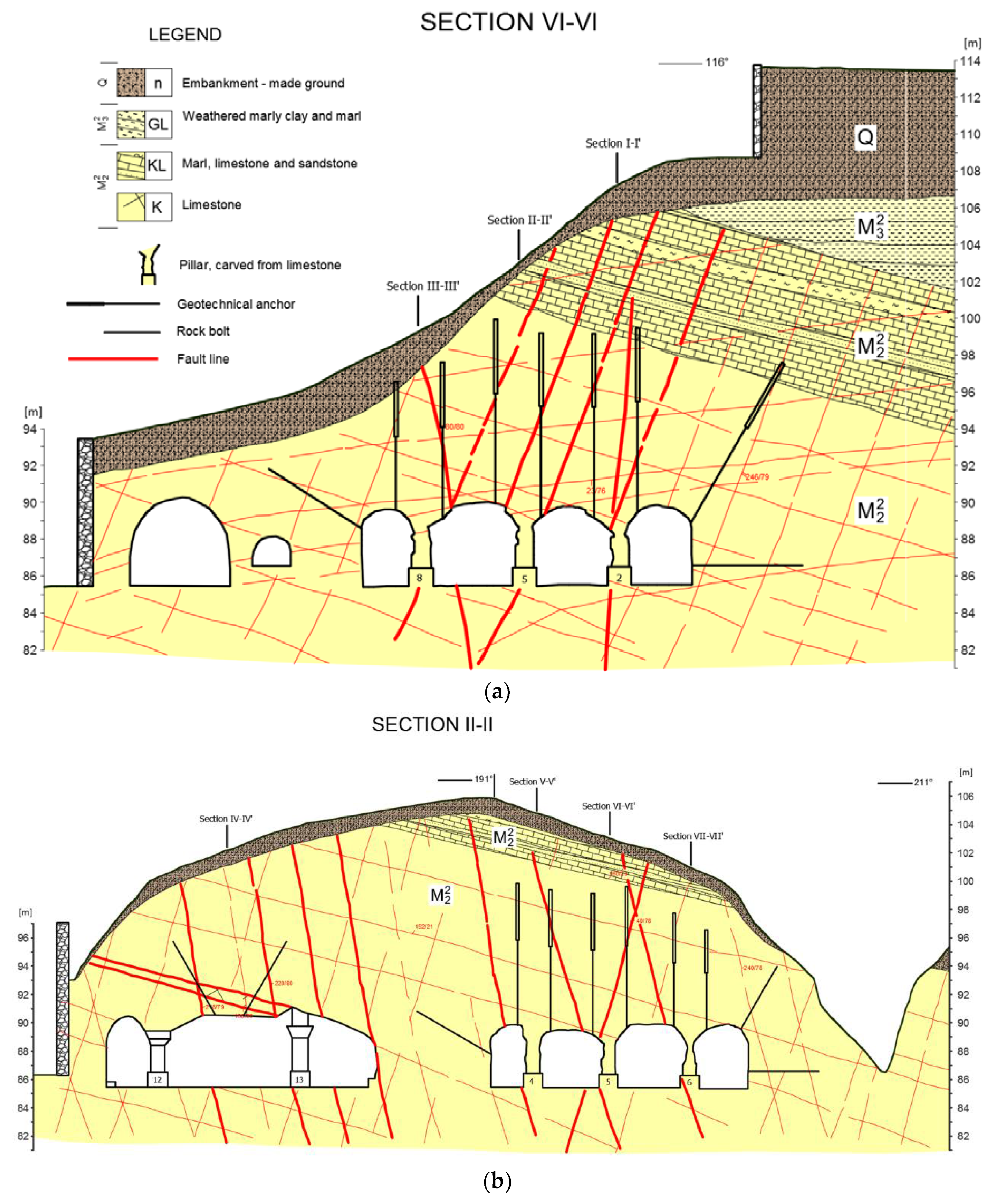
4]. It is understood that a hiatus (interruption of sedimentation) appears between the Tortonian and Pannonian strata, so the Sarmatian sediments (M13) are missing. The two characteristic longitudinal geological sections (II-II and VI-VI, see
Figure 1) of the galleries are shown in
Figure 2.
Tortonian sediments (M22: K, KL) represent a distinctively heterogeneous complex, which consist of carbonate sands, conglomerates, and carbonate sandstone with sands, but which are dominated by limestone. Limestone is manifested as an organogenic carbonate detritus, bonded by weak clayey cementing. The Tortonian sediments appear in 15–20 m thick packages.
The mineral composition is dominated by calcium carbonate (calcite-CaCO
3), while clay minerals (illite, kaolinite, smectite in traces) and fraction of limonite (Fe
2O
3, Fe(OH)
3) were also present. The ratio of carbonate detritus and the marly-clayey inclusions varies within the wide limits, and that significantly affects the mechanical characteristics and the porosity of the rock mass. In general, Tortonian sediments have low porosity, are not karstified and have relatively low bearing capacity. Both of the underground rooms are located within one sediment package of carbonate Tortonian sediments with a maximum overburden of some 35 m (sections VII-VII, shown in
Figure 1). The sediments are of banked texture, featuring some stratification so that locally noticeable sub-horizontal bedding planes can be isolated with a strike/dip orientation of 162/18 on average. The second sets of discontinuities, also indicated in
Figure 2 (orientations 239/79, 48/79 and 280/76), were caused by some moderate faulting and shearing. In their natural state these discontinuities are: (a) fully closed, (b) with persistence varying from 2 m to 8 m, (c) of undulated roughness and (d) no infilling. As it will be explained later, the second set of discontinuities was responsible for the wedge instabilities found in Room 1.
The Tortonian sediments are overlaid by marl, limestone and sandstone sediments. The complex is represented by strata of thicknesses varying from 5 m to 12 m. The stratified marl prevails in the lower part while the clayey-marly complex dominates the upper part. The Pannonian marls were created in deep-water conditions and are significantly changed physically and chemically (GL). This is mostly due to the influence of the weathering at the upper levels.
The Pannonian marls are overlaid by Quaternary (Q) (annotated by n in
Figure 2) deposits mixed with the embankment material with thicknesses ranging from 2 m on the slopes and up to 12 m on the plane. This material was deposited during the construction of the depot, as a cover, and consists of clay-marly debris mixed with the construction rubble and limestone blocks dispersed locally.
In terms of hydrogeological characteristics, the Tortonian sediments are relative insulators featuring low hydraulic conductivity. The galleries are located some 20 m above the groundwater table and are not under the direct influence or the fluctuation of underground water. The bedding planes are practically closed and they do not allow the filtration of significant quantities of the seepage water. The estimated coefficient of the filtration of this limestone is about k = 10−8 m/s but one order of magnitude more in the area of sub-vertical discontinuities. The seepage appears only temporarily within the galleries, usually after intensive precipitations in the form of drained water, which circulates downwards towards the aquifer zone. The quantities of water are small, due to low permeability, and they appear only along the larger fissures or are seen as high moisture areas around the discontinuities.
3. Materials and Methods of Testing
A written record exists for a series of different geotechnical site investigations, which were carried out since the 1960s in the Kalemegdan fortress area. The general development of structural geology was therefore well known as well as the material characteristics of the main strata, so only a single borehole and one excavation pit were carried out to determine the thickness of the bearing strata at the micro-location of the gunpowder depot [
5].
Geophysical site investigations comprising resistivity measurements and downhole seismic testing were carried out to complement the geological mapping of the site. A comprehensive set of laboratory tests were carried out according to EN ISO 17,892 group of standards [
5] and the ISRM suggested methods [
6]. Six samples were taken from the borehole, and from a separate block sample, with an aim to determine the mechanical characteristics of the various strata. The set of following laboratory tests were carried out: determination of unit weight and moisture, measurement of uniaxial compressive strength, measurement of tension strength using Brazilian test, measurement of elastic wave velocities for the determination of dynamic elastic modulus and Poisson´s coefficient, measurement of modulus of elasticity and the measurement of shear strength resistance using the direct shear apparatus. Material parameters, which were derived from the results of the laboratory testing, are presented in
Table 1.
4. The State of the Underground Galleries before the Remediation and Research Solutions
The excavation of the galleries was carried out using the room-and-pillars method. The stability of the underground rooms was ensured by leaving bearing columns of natural material behind. Nine columns of in-situ natural material were left in the each room to ensure the stability of the galleries. The columns were set at an appropriate 3 × 3 pattern at 5 m distances, as shown in
Figure 1. The columns were shaped carefully; their plan dimensions were approximately 1.5 m × 1.5 m at the narrowest section in the middle and increased upwards to form a curved pendentive achieving approximately plane dimensions of 3 m × 3 m at the contact point with the ceiling. The ceiling was slightly vaulted in both directions forming an underground cupola.
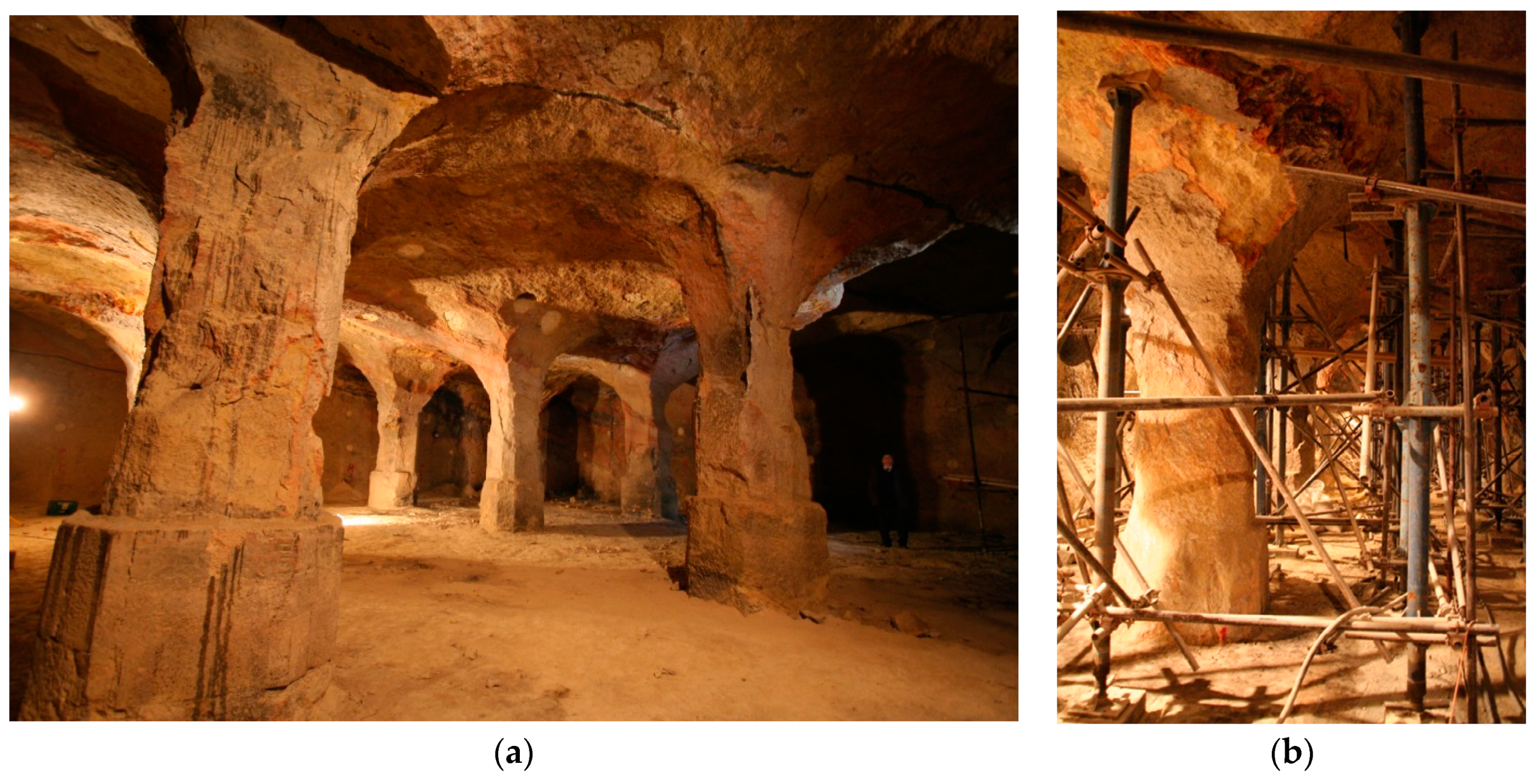
Being built in 1720 the galleries can be regarded as a first class engineering achievement within its historical context. Construction of the galleries was based on a clear understanding of the rock mass properties and the stress distribution around the underground openings. As it can be seen in
Figure 3a, the underground galleries demonstrate almost the artistic aesthetic quality of this underground space, which lasted some 250 years without the need for major remediation.
In order to preserve this monument, which has cultural heritage status, the authorities involved experts in archaeology, art history and conservation, who unanimously recommended the preservation of the current look of the galleries. However, the given state of the columns in Room 2 could not provide the needed stability requirements to withstand the current state of the weathering of the pillars. The research scope was to develop a solution in order to achieve stability of the underground space with minimal intervention inside the galleries, while the pillars needed to be preserved in the long-term in their delicate state.
These requirements were prompted by the inappropriate conservation of Room 1 carried out in 1950s, in which the nine columns of natural material were replaced by six columns made of reinforced concrete. The curved shapes of the columns were not replicated, so with no pendentive in place the concrete columns were not able to ensure the complete stability of the ceiling. Thus, in the middle of Room 1 there were notable signs of the abatement in the roof along the section of the missing columns IV-IV (see
Figure 1).
Seasonal changes in temperature and humidity, as well as the infiltration of rainwater over the course of time have resulted in moistening and dissolution of the weak clayey bonds of the carbonate rock. As emphasized by other authors [
7], there is a high probability that variations in the original thermo-hygrometric balance conditions caused chemical weathering by invoking several processes of crystallization, hydration, dehydration and polycyclical changes in the mineralogical phases. The main result of weathering was the loss of bearing capacity of the rock mass in the long term.
The weathering caused the columns to peel off gradually and thus reduce in size. One of the columns in Room 2 (No. 3 annotated in
Figure 1.) collapsed together with a part of the ceiling. There were therefore eight columns left in a damaged state in Room 2. Lessening of the active bearing surface caused the overloading of the columns, which resulted in partial buckling around the newly formed vertical discontinuities. In order to preserve the current state in Room 2 the client installed temporary scaffolding with the aim to aid the stability of the ceiling, as shown in
Figure 3b.
Since the replacement of the columns was not an option, the designers’ mission was to achieve the long-term stability while preserving the appearance of the inner space of the galleries. In the search for the most appropriate preservation method several variants were considered (ground improvement, construction of an upper gallery to reinforce the columns from the top, replication of the columns using natural stone and others). Due to aesthetic reasons, the client did not allow the use of reinforced concrete block columns cladded by the same limestone, which was a considered solution applied for the preservation of some rock-hewn underground openings in Cappadocia [
8].
The final solution was to suspend the ceiling by mobilizing the unused capacity of the rock mass above the gallery. This was achieved by using the combination of the active geotechnical anchors and the passive rock bolts. The research task was to anticipate the appropriate cumulative active force to suspend the deadweight of the material above the columns. At the same time, and adding to the complexity, the full covering of the deadweight was not desired, as some proportion of the load was beneficial to remain acting on the columns (once the mobilized normal stress in the columns drops to zero, the shear resistance strength in friction will diminish).
5. Analyses of Stability and Remedial Measures
Analytical equations are usually used for dimensioning the columns for the room-and-pillars excavation method. They are based on the determination of the tributary area of a particular column for which the calculated axial stresses are compared to the uniaxial compression strength of the rock mass [
9]. Several empirical correlations can be found in the literature [
10] connecting pillar strength with the uniaxial compression strength of the rock mass in the form of the power function of the weight and the height of the pillar. Also, other authors [
11] have proposed a series of curves for the estimation of pillar strength based on numerical modelling considering different failure mechanisms inside the pillars for a range of rock mass qualities. However, both the analytical and empirical methods have the disadvantage of using prescribed constants, which are difficult to determine in practice. Generally, they cannot be considered applicable for a variety of different boundary conditions, especially so in nonhomogeneous and structurally variable rock mass. For this reason, only numerical methods were used to develop an adequate solution for the rehabilitation of the gunpowder depot.
There were two issues regarding the stability of the ceiling of the gunpowder depot: (a) the local instability of the separate blocks caused by the unfavourable spatial orientation of the intersecting joints in Room 1 and (b) the global instability caused by the on-going deterioration of the columns in Room 2.
In Room 1 the local instabilities were pronounced along the missing row of the columns in the middle of the room, i.e., along the profile IV-IV (seen in sections II-II in
Figure 2). The local instabilities were addressed using the program Unwedge [
12]. Safety factors were calculated for the potentially unstable wedges and the support measures were modelled by the utilisation of the passive rock bolts. It was concluded that the systematic anchoring using the rock bolts of 5 m to 8 m length with the nominal capacity of 250 kN could ensure the stability of the potentially unstable blocks in Room 1 up to the required safety factor of FOS = 1.25.
A comprehensive set of analyses using the finite element method were carried out to address the global instability of Room 2. The purpose of the analysis was: (a) to appropriately distribute the pre-stressed anchors across the ceiling so that a homogeneous stress field is achieved in the area of the roof, (b) to determine the free length, the fixed length and the capacity of the pre-stressed anchors and (c) to distribute the passive rock bolts to complement the action of the pre-stressed anchors.
The geotechnical model was developed to take into account the initial stresses and the history of the works including the rehabilitation measures, which had been earlier applied in Room 1. Simplifications in terms of geometry had to be adopted so that the problem could be posed in the form of a boundary value problem and resolved using the finite element method. The capabilities of the software packages used for the calculations were considered as well. Due to different approaches in modelling of the anchor systems, the dual analyses were carried out using the two finite element programs; Phase2 [
13], and Plaxis 2D [
14]. No significant differences were found between the two so in continuation only the Plaxis 2D results will be shown and interpreted.
The material parameters used in the analyses for different geotechnical units are presented in
Table 2. The lower bound values given in the table were used for checking the ultimate stability for the worse possible conditions. There was no expectation of significant plastic behaviour so only the Mohr-Coulomb constitutive model was used for all the geotechnical units. The material parameters were derived from the laboratory and in-situ tests, described in the previous section. These material parameters were further extrapolated for the rock matrix at large scale using the rock characterisation methods ([
15,
16]).
Table 2 also contains an estimate of the lower bound values (e.g., residual values for the rock columns) for the material parameters.
Seven sets of 2D analyses were carried out for the each of the cross-sections annotated in
Figure 1. The different stages of analyses were used to derive a reasonable estimate of the stress-deformation state of the rock mass prior to the application of the remedial measures. The following stages of the analyses were carried out: (1) determination of the in situ stresses prior to the excavation, (2) excavations of both rooms, (3) replacement of columns in Room 1, (4) collapse of column No. 3 in Room 2, and (5) reduction of material parameters in the columns to residual values.
The rehabilitation measures were modelled using the stages in the continuation of analyses as follows: (6) application of the passive anchors in both Room 1 and Room 2, (7) installation of the pre-stressed anchors in Room 2, (8) full loss of capacity of the columns in Room 2, and (9) c-φ reduction analyses for the determination of the factor of safety for the ultimate limit state.
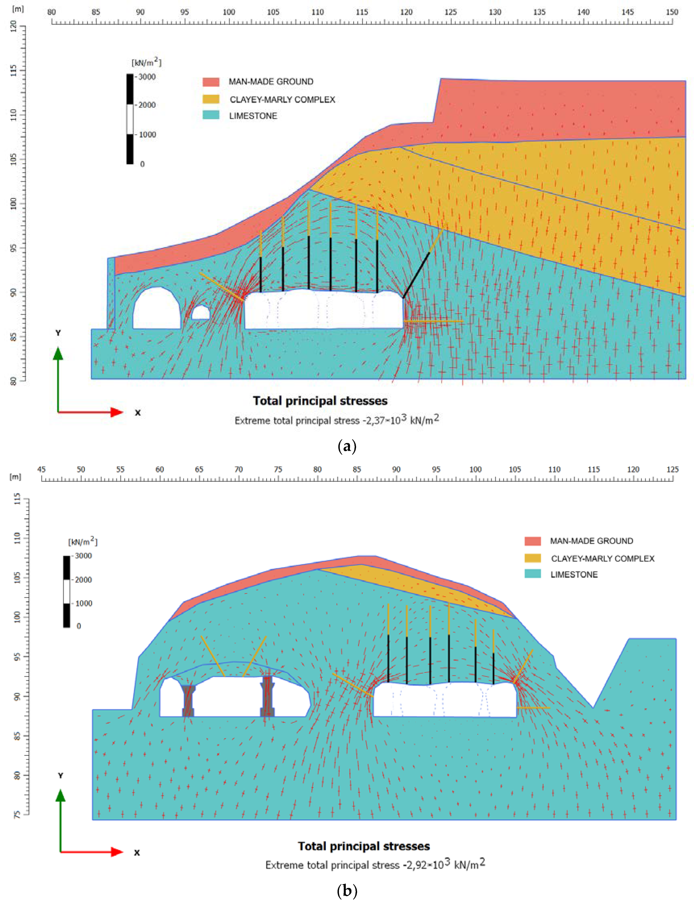
The characteristic results of the analyses for sections II-II and VI-VI are shown in
Figure 4 in the form of a distribution of the directions of the principle stresses. The results of the analyses show that the decay of the pillars and the proportional loss of their load capacity would cause a formation of the new static system in the surrounding rock mass. The characteristic feature of the new static system was that the inner forces in the rock mass would form a natural arch in the form of 3D vault, rising from the sides of the room and arching above the stress-relieved rock mass. This is seen in
Figure 4a,b as the arching effect of the principal stresses situated above the low stressed area. As the new static system is formed, the stress-relieved rock mass becomes unstable due to the loss of the confining stresses. The confining stress was needed to provide the shear strength along the discontinuities and in the rock mass itself. In static terms, the unloaded rock mass below the 3D vault becomes an additional dead load for the columns. Additional load caused the damage of the columns, which was further amplified by the weathering process.
Analyses showed that the pre-stressed anchors should be fixed in the area of principal stress arch, where the higher confining stresses are concentrated. They needed to be distributed evenly and predominantly in the vertical direction to counteract the deadweight of the stress-relieved roof. The length of the anchors was set to be between 7 m and 10 m, with the fixity length adapted to remain within the stress arch and within the limestone stratum wherever possible. The anchors were designed to actively take the dead load of approximately 1150 tonnes, some 80% of 1450 tonnes, which was the estimated full dead load weight of the unloaded rock mass above the columns. The rest of the load, i.e., some 300 tonnes, was left to act beneficially on the columns, as previously discussed.
Generally, the analyses showed that passive anchors should be distributed systematically in the area in which the stress concentrations were detected. Five to eight meters long rock bolts of nominal capacity of 250 kN were installed perpendicular to the curved walls of the room to counteract the tension stresses, as indicated in
Figure 4a,b.
The location of passive and active anchors is also presented in the characteristic cross-sections VI-VI and II-II, shown in
Figure 2.
Figure 4a,b best demonstrate the application of the designer concepts: a) the predominantly vertical pre-stressed anchors were fixed in the area of the arch well above the stress-relief zone, (seen in the figures as the low stressed area above the columns and below the naturally occurring load bearing vault), while the passive anchors are located at the area of stress concentration at the corners and the sides of the Room 2. The maximum calculated displacement was low, as expected, up to the mark of 2 mm. The calculated values for factor of safety for ultimate state varied from section to section; the highest was in section II-II with FOS = 2.05; the lowest in section V-V with FOS = 1.30.
6. Application of the Rehabilitation Measures
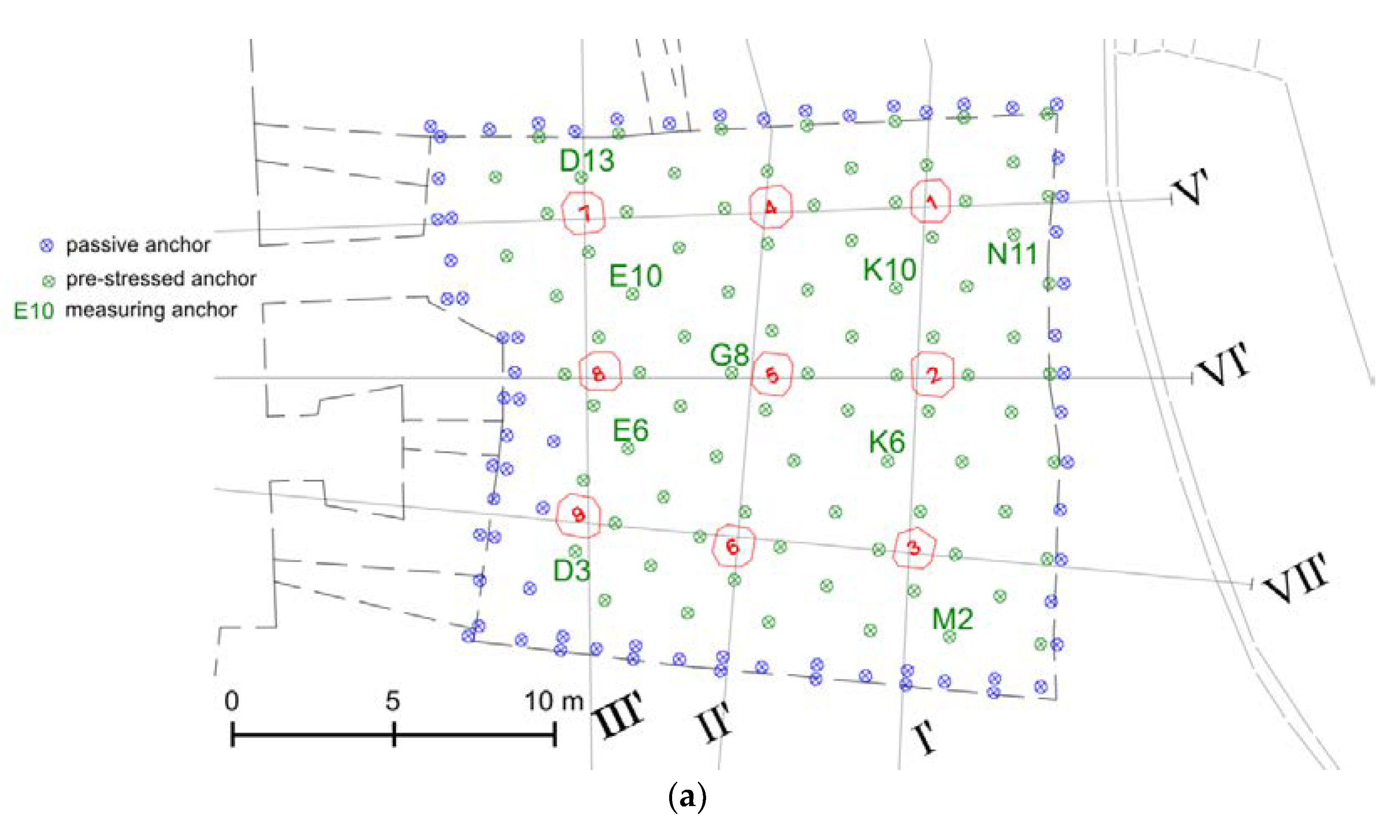
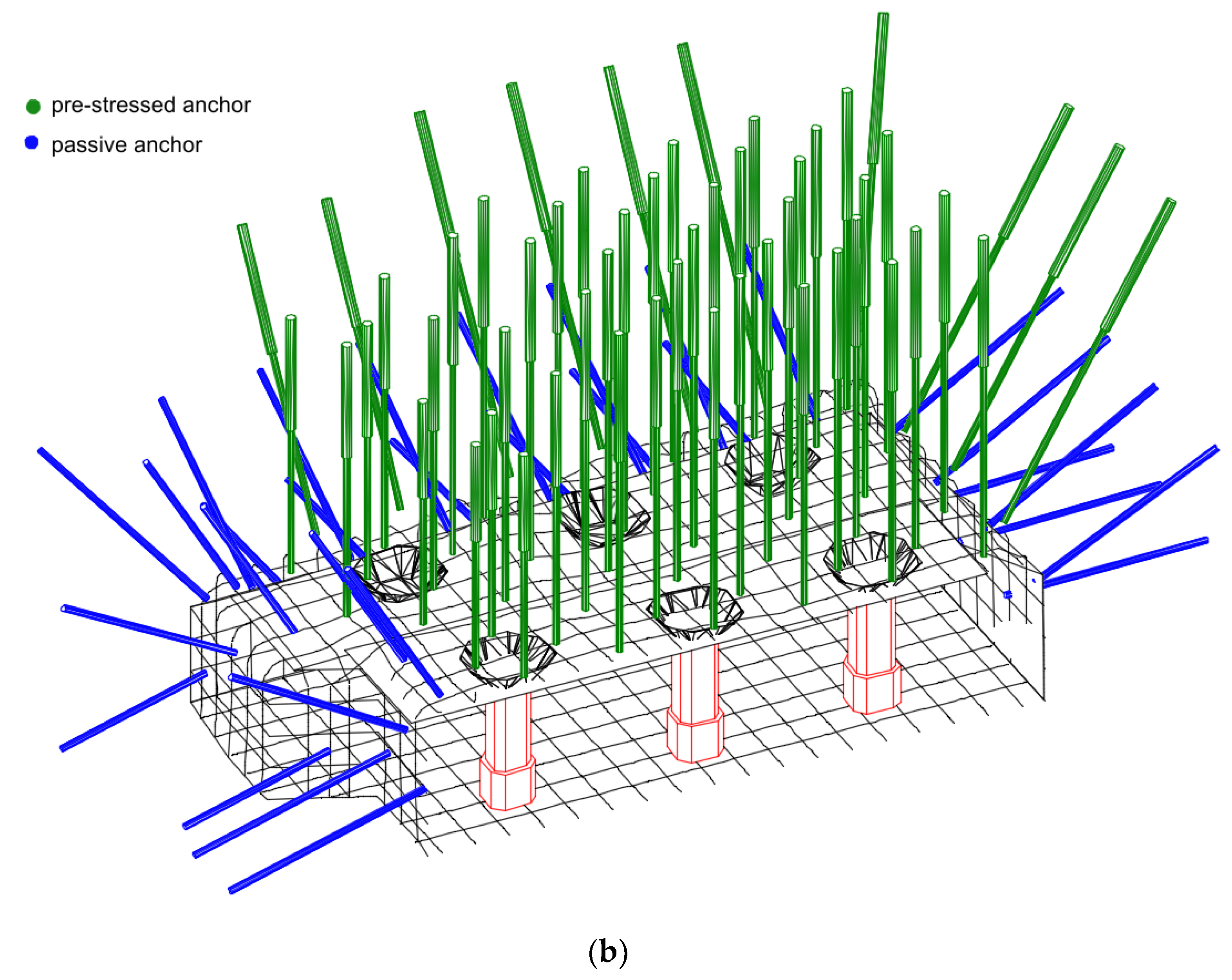
The approximate spatial position and the distribution of both types of anchors is schematically presented in the form of a layout presented in
Figure 5a and as an axonometric view of the eastern half of Room 2 in
Figure 5b (for the sake of clarity only the eastern half is shown; the western half is almost symmetrical). A total of 84 pre-stressed anchors were installed following an approximate pattern of 2.5 m × 1.5 m. The action of each column was directly supported by the four vertical anchors installed next to it, as indicated in the figure. The active anchors contained two steel tendons of diameter Ø 15.7 mm (0,6") with yield and maximal capacity in tension of f
y/f
tk = 1650/1860 N/mm
2, leading to the maximal anchor capacity of about 550 kN. Given that the anchors were pre-stressed between 130 kN and 200 kN they were only mobilized up to 35–40% of their full capacity. The rest of the capacity was regarded as a necessary reserve, which will be activated in the case of the complete loss of capacity of the columns in the long-term.
Approximately 80 passive anchors were installed at the edges and perpendicularly on the contour of Room 2 to complement the action of the pre-stressed anchors. Another 32 passive anchors were installed in Room 1 to prevent the local wedges instabilities along the section IV-IV, as previously commented.
In order to preserve the appearance of the ceiling the heads of the anchors were embedded in the rock mass, as shown in
Figure 6. Boreholes of up to 30 cm in diameter were covered using rock material of almost the same characteristics and colour so that the visual impact of the rehabilitation on the ceiling was low. As seen in
Figure 3a, the locations of the anchors can be recognized as yellow dots on the ceiling, but clearly these do not disfigure the original appearance of the gallery roof.
Prior to the installation of the anchors, the injection grouting of discontinuities was carried out. The grouting was needed to homogenize and improve the load-bearing capacity of the rock mass. This measure also complemented the main rehabilitation action of the pre-stressed anchors so that the suspension of the ceiling and the improved state of discontinuities prevented the further degradation of the rock mass.
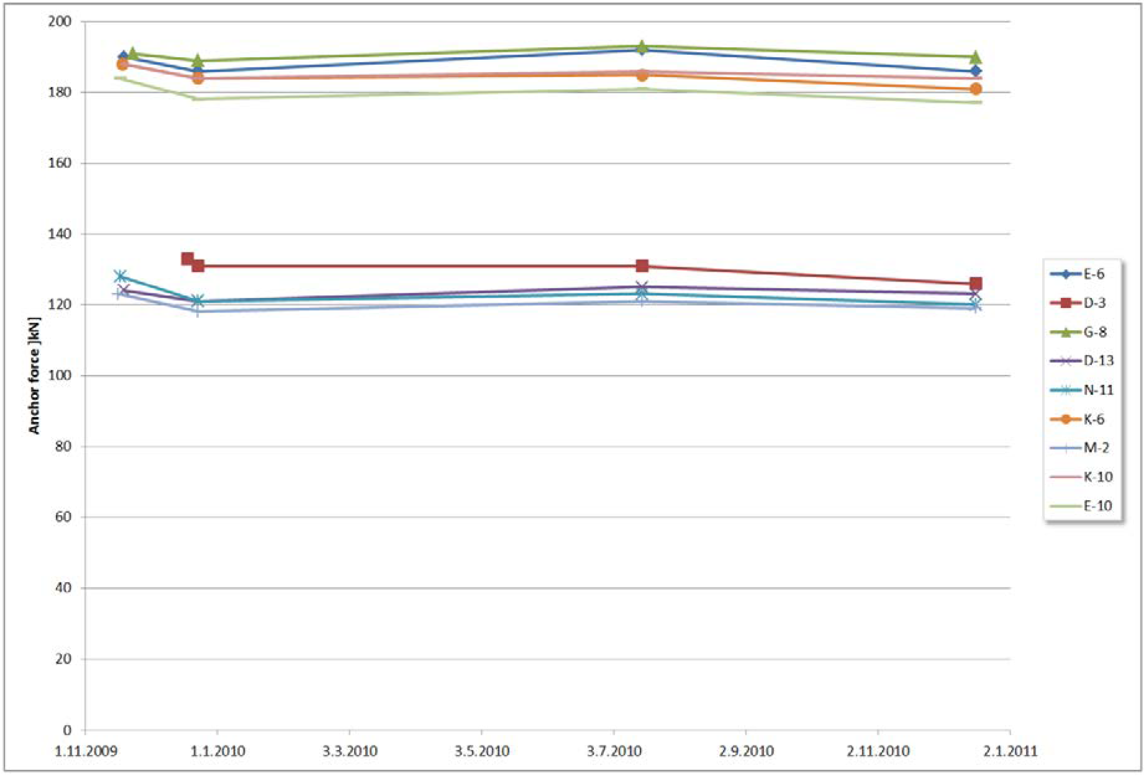
As part of the rehabilitation, a comprehensive monitoring system was installed. The following actions were carried out at regular intervals: (a) reading of the load cells, which were installed at nine control anchors (measuring locations are shown in
Figure 5a), and (b) geodetic survey of the target points installed at the ceilings of both Room 1 and Room 2. The results of reading the load cells, including the zero measurement, are presented in the diagram in
Figure 7 for the period of the first two years after the construction. As it can be seen, two years after the rehabilitation, the active forces in the anchors were predominantly constant. An oscillation of the active force of several per cent seen on the diagram is related to the seasonal oscillation of the external temperature. The geodetic survey showed the maximum settlement of the roof of some 3 mm, which was higher than predicted in the numerical analyses but still within reasonable expectation. The measurements carried out in the long-term up to 2020 did not show any significant deviations from these results.
7. Summary and Conclusions
The objective of the paper was to present the delicate rehabilitation measures applied to preserve an underground gallery, which was built approximately 300 years ago in soft rock. The gallery, which was built using the room and pillars method, had been originally used as a two-room gunpowder depot. In 2008, the gallery was in a state of collapse. The damage was caused by the infiltration of rainwater over the course of time, which resulted in moistening and dissolving of the weak clayey bonds of the carbonate rock. Also, it is very likely that variations in the original thermo-hygrometric balance conditions caused chemical weathering, which further undermined the capacity of the rock mass in the long term. An immediate intervention was needed to prevent any further damage.
The rehabilitation measures were carried out to satisfy the rigorous conditions set by the authorities in terms of preservation of the current state of the columns. Since Room 1 was inappropriately rehabilitated in the 1950s there was only the possibility of full preservation of Room 2. The main requirement was to preserve the current appearance of the Room 2, despite the fact that the columns were in a poor state and had already lost the majority of their bearing capacity.
The structural geology assessment, supported by comprehensive site investigation, was the key instrument in research to develop the appropriate solution. Materials were tested using a set of comprehensive and routine laboratory tests. The thickness and the spatial distribution of the Tortonian limestone located above the gallery were determined by the borehole mapping and geophysical site investigations comprising resistivity measurements and downhole seismic testing. The spatial distribution of this stratum was of significant importance. This was the only material of required capacity and appropriate thickness available to take the load of the newly established stress state. The solution was to suspend the stress-relieved rock mass using active geotechnical anchors, for which the area of the fixities was located within the the naturally formed arch in the rock mass above the gallery. The passive anchors were used to complement the action of active anchors by taking the tension forces at the side walls and the corners of the underground room.
Careful drilling works, development and the execution of the detail of the embedment of the anchor heads were needed to ensure minimal impact of the rehabilitation on the appearance of Room 2. The controversial requirement of preserving the look of the columns that had lost their bearing function was achieved with minimal disturbance of the rock mass. A comprehensive geotechnical monitoring, which lasted 10 years and included geodetic survey and the measurement of the anchor forces, proved the long-term stability of the applied remedial measures.
The gallery remained closed up to now due to concerns that the utilization of the rooms and human presence will cause the microclimate conditions of relative humidity, temperature and air flow, which will advance and accelerate the weathering. At the moment, only the monitoring of the microclimate parameters are carried out to understand the current weathering conditions, which can be used as a benchmark for future reference.


