1. Introduction
Waste management problems have become a great threat to the natural environment in developing countries and efficient solutions are urgently required [
1]. Many waste disposal sites in Thailand are sources of environmental pollution because waste is still largely disposed in open-dumping sites without effective safety and control measurements [
2,
3]. This situation poses a serious risk to the environment and human health [
4]. Around the world, sanitary landfills are widely used as the primary facility for the ultimate disposal of municipal solid waste; an inevitable consequence of this practice is leachate generation [
5,
6].
Leachate is contaminated water that contains high concentrations of organic and inorganic compounds [
7]. It is produced when the water content is squeezed out of incoming waste as well as from rain that percolates through the cover layers and accumulates in the waste [
8]. In the absence of a confining barrier beneath or surrounding the waste disposal site, this leachate can migrate and may seriously pollute natural water sources, especially via the groundwater path [
9,
10,
11,
12].
Although today, waste disposal sites often require a technical leachate barrier, this cannot guarantee long-term stability with regard to how long it can operate without being damaged. The synthetic barrier alone may eventually break, and it cannot exactly replace a geological barrier [
13]. If there is no appropriate natural barrier, the contamination of groundwater is almost certain. Thus, the long-term stability of a geological barrier can act as a superior security system for modern landfills [
14]. The barrier properties of rock or sediment will hinder leachate’s ability to infiltrate into the subsurface and groundwater system. These properties are mainly a high content of clay, which has a low effective porosity, low permeability, and high contaminant retention capacity [
15,
16].
In order to protect against the risk of pollution, the location of waste disposal sites evidently requires the consideration of numerous criteria [
13], with hydrogeological conditions as well as geological and geotechnical characteristics being the most critical [
16]. From the perspective of landfill standards, a site will only be considered as suitable for landfill operations if it meets basic requirements, including being superficially underlain by a considerable depth of relatively impervious soil or rock materials which do not only serve as a barrier to protect groundwater resources but are also suitable as final cover material; it is also required that groundwater levels be far below the expected total thickness of landfill cells [
13,
17]. The construction of surface cover and liner in such a way that they provide a barrier to prevent direct contact with waste materials and minimize or eliminate infiltration of precipitation through the waste materials (i.e., leachate formation) is currently the main approach used to manage human and ecological risks at a site [
18].
Waste management has, for many years, presented serious challenges in Thailand. Khon Kaen, the third largest city in northeast Thailand, is one of the most significant sources of this waste. There has been increased municipal solid waste from households due to increased municipal activities [
1,
19]. Khon Kaen is one of the most important cities in northeast Thailand. For more than 50 years [
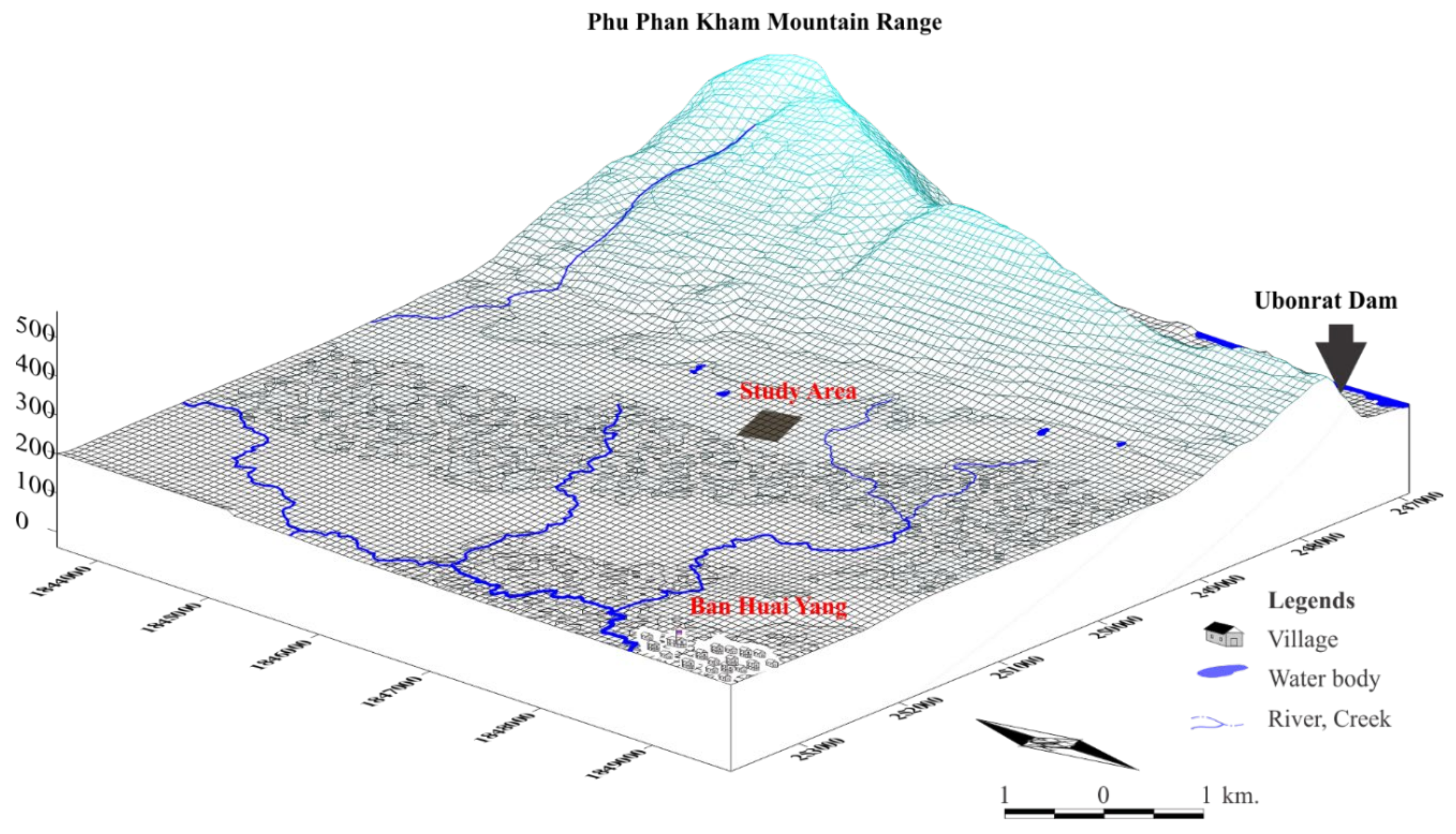
20], all varieties of waste, such as domestic, medical, commercial, and industrial wastes, have been dumped at Ban Kham Bon landfill site (
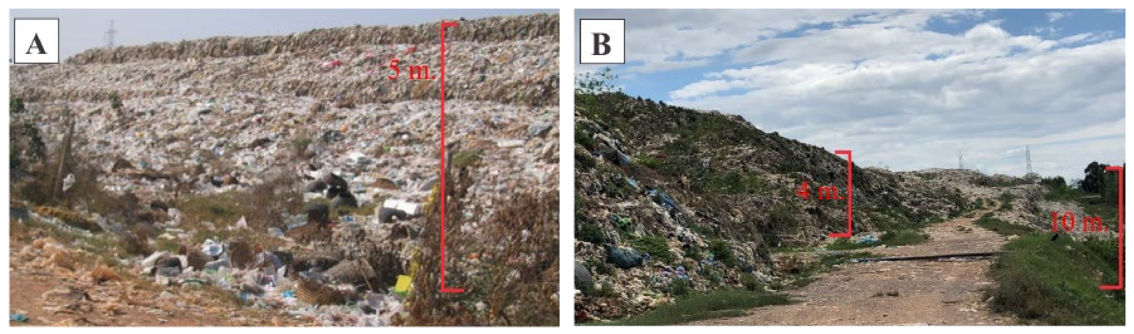
Figure 1), which has served as the central waste disposal site not only for Khon Kaen municipality, but also for nearby sanitary subdistricts. Generally, more than 350 t of waste is generated in a day [
19]. Nowadays, waste is dumped carelessly and scattered all around the existing landfill. This results in an uncontrolled environmental impact in the form of visual pollution, odor, leachate, fire and smoke, slope instability, and virus-spreading vectors [
21,
22]. This landfill site is only expected to be available for a few more years, as it is almost completely filled. This has forced the municipality to relocate to a new disposal site.
A selected site suitable for landfill construction has, on occasion, been severely protested against by locals. This issue can cause the proposed landfill to be relocated to an environmentally sensitive area that is far from the community. Based on the Khon Kaen Provincial Administration Organization and Khon Kaen University cooperation, a new Khon Kaen waste disposal site has been selected in Khok Sung Subdistrict, Ubonrat District, that is situated in a highly environmentally sensitive area [
23,
24]. Plans have been made to establish an incinerator, landfill, and compost at the site. The preliminary environmental impact assessment was carried out by the Environmental and Hazardous Substance Management (EHSM), Khon Kaen University. As a result, it implied that groundwater contamination prevention can be carried out, and the waste disposal site can be established [
25]. However, the geological, hydrogeological, and geotechnical properties of the site have not yet been studied. Therefore, this research focuses on the main objective of investigations of subsurface materials and groundwater systems of the proposed waste disposal site: to assess whether or not the soils and rocks have low permeability and a capacity to retain contaminants. They can act very effectively as a natural barrier against groundwater pollution from the waste site leachate. It is possible that the state-of-the-art methods indicate to the public that the subsurface of a waste disposal site can function as a barrier, preventing the entry of pollutants into the environment. If so, construction of the waste disposal site will continue to proceed as planned.
2. Description of the Study Area
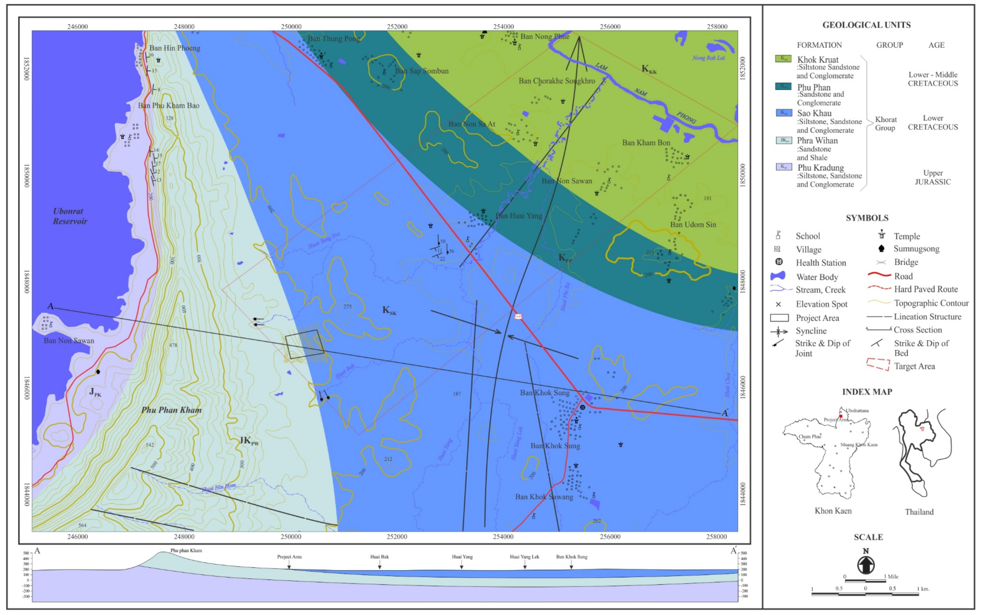
The proposed waste disposal site is located about 52 km northwest of Khon Kaen City. It is situated in Khok Sung Subdistrict, Ubonrat District, Khon Kaen Province, Thailand, and occupies approximately 0.32 km
2. The proposed site is approximately 4.5 km from the nearest community. It is a sparsely populated area and is easily accessible by hard paved roads. Detailed maps are shown in
Figure 2 and
Figure 3.
The study area is located on a foothill, as a part of the Phu Phan Kham mountain range, with elevation ranging from 195 to 215 m. The Phu Phan Kham Range trends north–south, dividing the Ubolratana Reservoir from the Nam Phong Subbasin. It slopes from west to east. The rolling hills, river terraces, mountain range and mountain terraces provide a distinct topography. The nearby creeks flood in the rainy season but are dry for the rest of the year. The creeks flow eastward down the gradient to form a tributary of the Nam Phong River.
Generally, the current patterns of land use can be described based on interpretation from high-resolution satellite imagery and field investigations. They reveal that the adjacent catchments are predominantly agricultural areas and forest. The common upland crop cultivations are sugarcane, cassava, rubber tree, and eucalyptus which cover the areas of undulating hill and foothill slope. The soil covering the undulated terrain is low in fertility, whereas rainfed rice can be grown on the flat-lying paddy fields and gently undulating terrain during the rainy season. The open to dense deciduous forest is in the area of the hilly to mountainous topography. The study area is located in disturbed forest.
3. Methodology
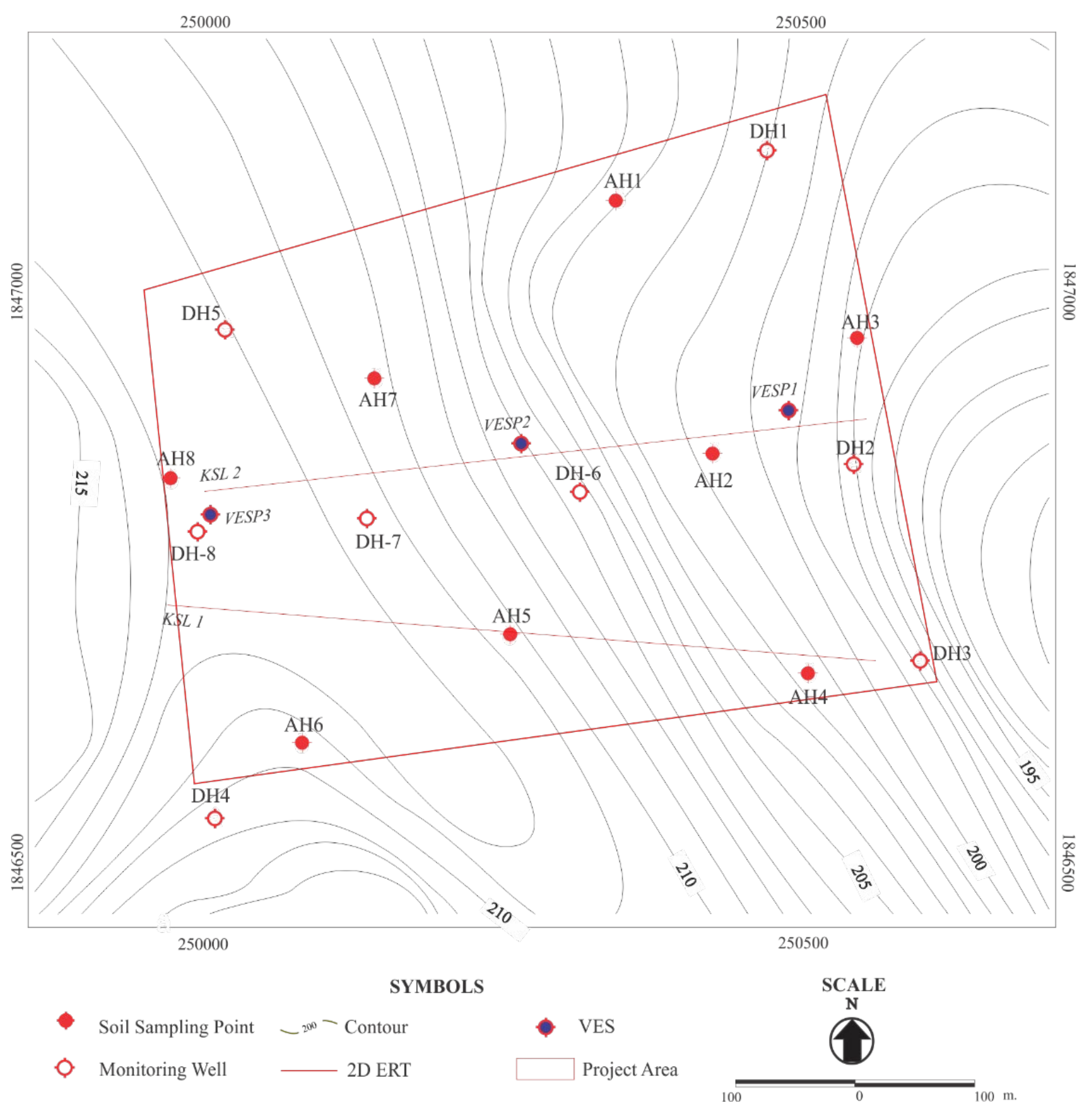
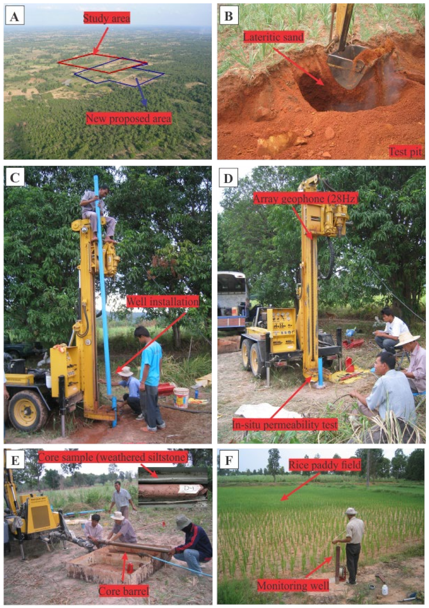
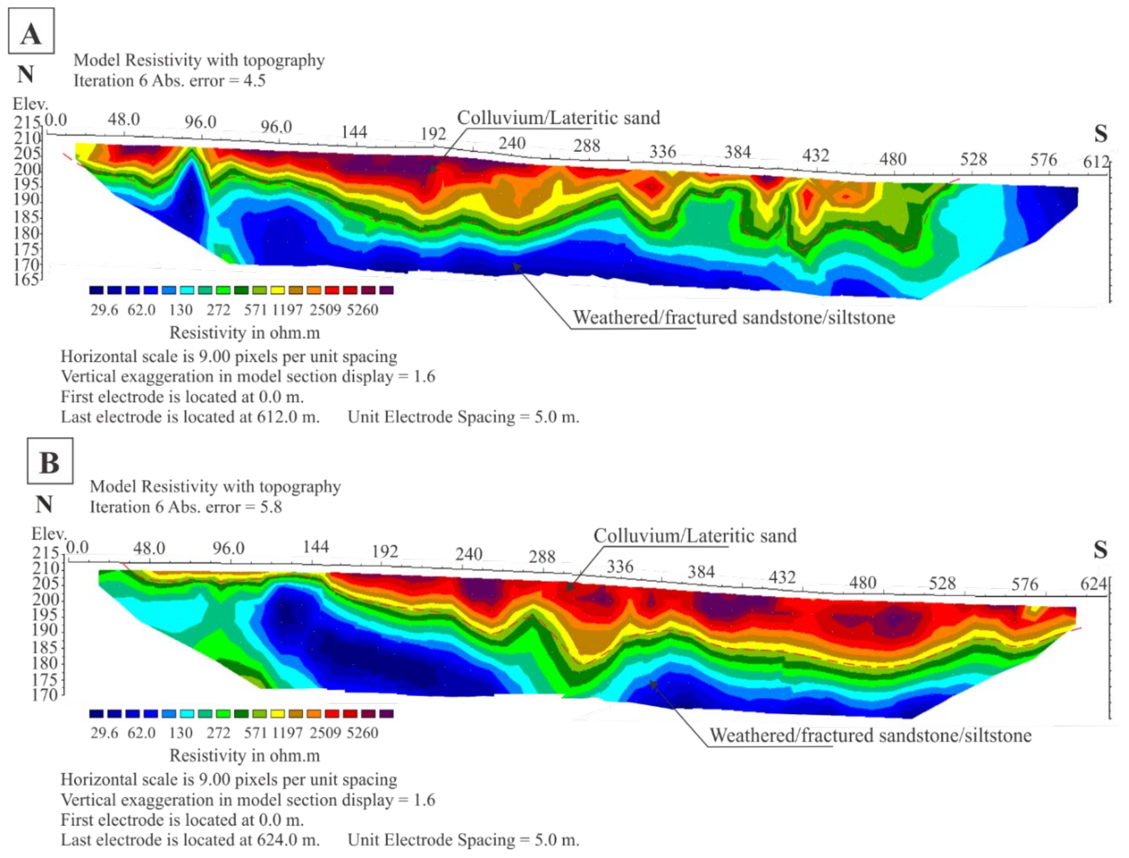
The aerial photograph interpretation was performed following field surveys by studying outcrops to verify the geological features identified on aerial photographs. Topographic mapping was undertaken to establish the detailed topography. Two lines (KSL1 and KSL2) of 2D electrical resistivity tomography (ERT) were conducted by deploying electrodes down slope (
Figure 3). For each line, 48 electrodes were spaced 5 m apart, with the electrodes arranged in a Wenner–Schlumberger array, and the roll-along technique was applied.
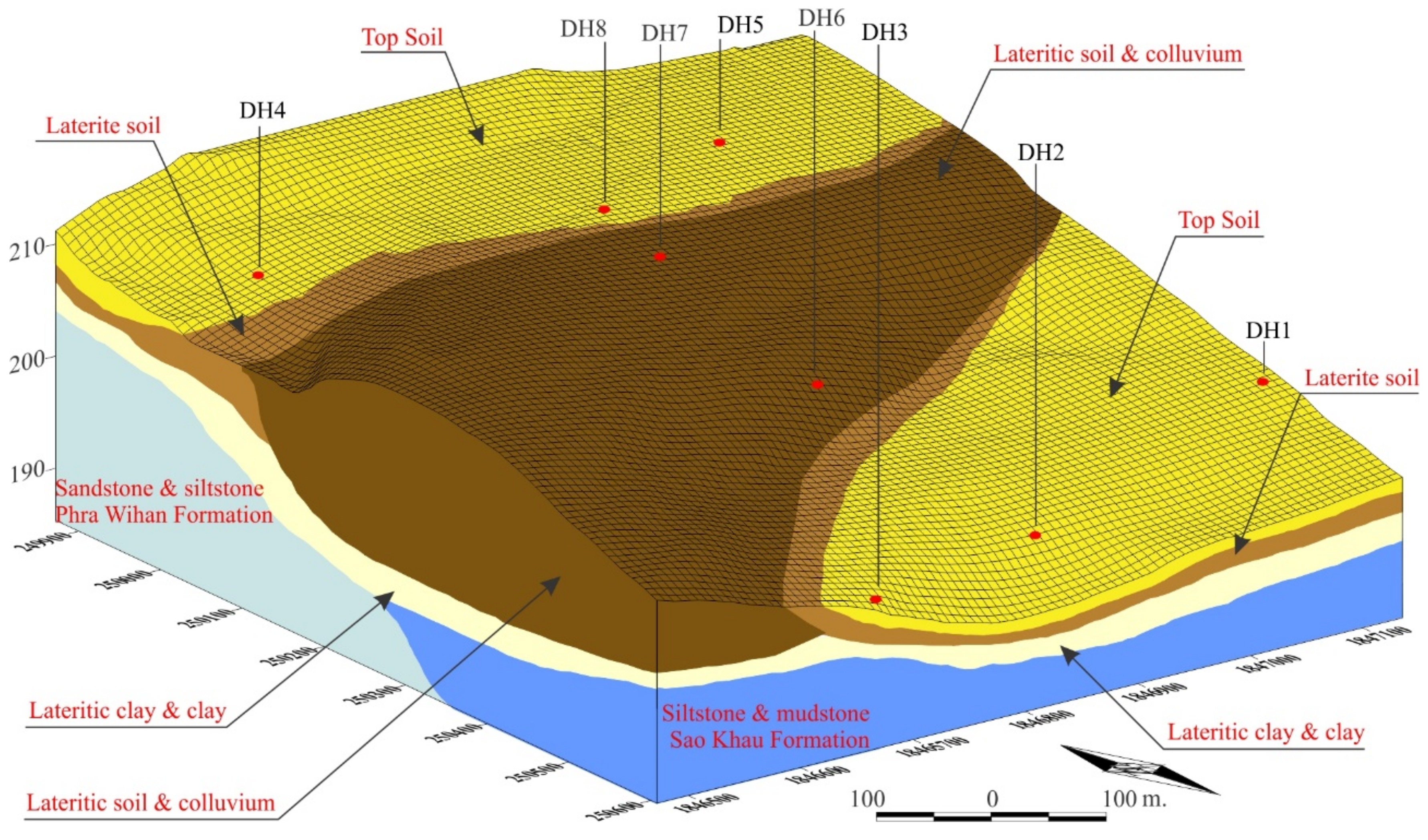
Eight augers, together with core drillings of DH1 to DH8 (
Figure 3 and
Figure 4), were bored for geotechnical data collection. The standard penetration test (SPT) and field permeability tests were carried out during drilling. The SPT was conducted to determine stiffness and strength of soil, while the permeability test was performed to determine the natural permeability of each soil layer. Field permeability tests at different depths were normally conducted at 1.5 m intervals. The variable head method was performed to determine the permeability of the soil layer. The five boreholes of DH1 to DH5 were enlarged for monitoring the well installation. Most of the wells were drilled at a depth of 10 m below the ground surface. The wells were installed to observe long-term water table fluctuations and facilitate groundwater sample collection. Pitting was conducted to provide detailed information on the strength, stratification, and discontinuity of in situ soil near the surface deposit. Two shallow trial pits were excavated by backhoe excavator at about 2–2.5 m depth.
Nine bulk soil samples were collected from 5 drilling holes of DH1 to DH5. Another nine samples were collected from shallow hand auger drilling of AH1 to AH8. They were scattered over the study area, ranging in depth from 0.5 to 5.0 m. All 18 disturbed soil samples were tested in a laboratory to verify geotechnical properties for liner and cover material. They were subjected to classification tests, including natural moisture content, grain size analysis (ASTM D 495), grain size analysis (ASTM D 422), Atterberg limits (ASTM D 4318), falling head permeability test (ASTM D5084-16a) and standard proctor compaction (ASTM D 698) with a permeability test after compaction. All parameters were identified following the standard of American Society for Testing Materials (ASTM).
The groundwater level was measured in and outside the study area. Eighteen groundwater samples were collected inside and outside the study area. The 5 samples that were collected from shallow wells inside the study area were analyzed for physicochemical parameters. Another 13 groundwater samples that were collected from nearby communities around the study area were analyzed for their physical parameters. The quality of the groundwater in place was analyzed to monitor the pollutant in the future. All groundwater samples were then subjected to physicochemical analyses in accordance with APHA standards [
26].
4. Results and Discussion
4.1. Geological Assessment
Based on an analysis, there was no evidence of major hazards or unstable areas. No active fault zone was identified. The geological structure shows three lineaments in the north–south, northeast–southwest and northwest–southeast trends. Major anticline and syncline are located in the west and east of the study area and tend in the north–south orientation. The syncline likely plunges toward the north. The proposed site is situated in the eastern limb of a large anticline. The strata idicates a monoclinal structure. They strike approximately north–south and dip gently southeast, normally less than 20 degrees towards the axis of the syncline. The joint sets are oriented in northwest and southeast directions. They dip toward the southwest, ranging from 70° to vertical and are defined as the continual joint. The joint intervals in the rock layer range from 1 to 6 m. The infilled materials are loose soil.
Unconsolidated sediments cover the bedrock, ranging from 5 to 6 m in thickness, except for some parts where the outcrop is exposed. There is a wide distribution, from top to bottom, of topsoil, colluvium, laterite soil, lateritic clay, and weathered rock. These materials vary in size. The fine-grained topsoil, lateritic soil, and lateritic clay can restrict rainfall infiltration and promote runoff from the active work area. The colluvium has high permeability and can be used as a drainage layer but is not appropriate as a site for landfill construction. The conceptual layout of the site excavation provides sufficient material to be utilized as soil cover, a drainage layer, and as a liner within the boundaries of the waste disposal site.
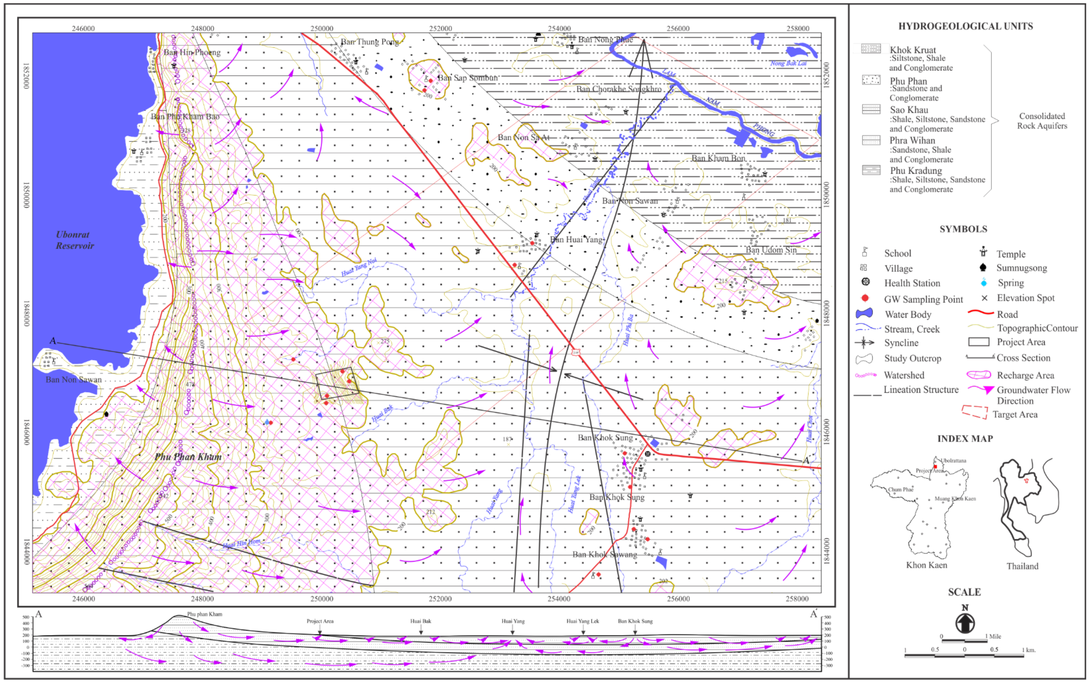
The rocks consist of the red bed member of the Jurassic–Cretaceous formation of conglomeratic sandstone/sandstone of the Phra Wihan formation (PW) and siltstone/mudstone of Sao Khua formation (SK) of the Khorat group (
Figure 5). The shallow bedrock in the center part of the study area has high fracture and its orientation is unclear. While DH6 and DH7 were boring, the entire drilling mud was lost and therefore could not carry any cutting rock to the surface, with more than 400 L lost within 15 min. Moreover, this layer likely extended from the surface to greater than 20 m in depth to form resistivity pseudosections. Therefore, this section must be improved if there is disposal activity.
The Phra Wiharn bedrock contains joint stat are separated by more than 2 to 6 m. The direction of the joint systems as seen in the regional and adjacent areas is in the north–south and east–west directions. The contact zone likely contains more water content so that it can accumulate affluent from shallow groundwater, and the vulnerable bedrock has frequent joints and fractures. Nevertheless, the spacing is not wide, although the problems may have an effect if the liner is not efficient and has no appropriate prevention measurement.
The proposed waste disposal site is situated in the gently rolling topography at the foothill of Phu Phan Kham Mountain Range. The soil encountered is not collapsible and the terrain is not a risky slope. There is no floodplain in the nearby area. The karst terrain is not presented in the red bedrock formation underlying the site. There is no instability concerning the proper control of earthwork construction and the project site is safe from other geologically hazardous events.
4.2. Hydrogeological Assessment
The proposed waste disposal site is located in the region’s primary hydrologic recharge area and the main target area is identified as a quadrangle in
Figure 6. The groundwater mainly originates as rainwater infiltration, which inflows through the unsaturated zone into the groundwater reservoir. The local flow of groundwater is from the foothill slope toward the Tung Pong community and ends up at the Nam Phong River. The groundwater level varies according to the topography, decreasing from approximately 6.5 m below the ground surface on rolling land to 1 m below surface near drainage. The hydrogeological units can be classified into two main aquifers: an unconfined aquifer (unconsolidated soils) and a semi-confined aquifer (fractured rock). Five monitoring wells (DH1-DH5) were installed, and the groundwater samples were sampled for groundwater quality. All sample were slightly acidic, with pH values between 6.35 and 6.66 (mean 6.48) (
Table 1). The average values of total dissolved solids (TDS) and total hardness (TH) are both below 400 mg/L and the electrical conductivity (EC) is less than 500 μs/cm. The concentrations of cations (Na
+, K
+, Ca
2+, and Mg
2+), anions (Cl
−, NO
3−, HCO
3−, and SO
42−), and heavy metals (Cd, Pb, Zn, Cu, Mn, and Fe) are relatively low. Based on the analyses, the groundwater quality meets the PCD 2004 [
27] standards for drinking water.
From the 2D ERT profiles (
Figure 7), they obviously indicate that groundwater flows underneath the high-resistivity zone (solid color) from the higher elevation in the west down to the lower elevation (light color) in the east. There is likely a high accumulation of groundwater in the lateritic clay layer or between the weathered contact zone of rock formations. Groundwater seepage was noted where there was an old drainage system and an existing paddy field during a site visit in the rainy season.
At the high elevation in the west of the study area, the groundwater table is about 6 m below the ground surface, while at the lower elevation in the east, it is near the ground surface. Therefore, the waste disposal site should be located in the higher elevations of the site to avoid areas where the groundwater is at a shallow depth. Thus, the western margin of the study area is more suitable. The shallow aquifer is important in this area. The groundwater has a low yield, but it is the main groundwater reservoir and is sufficient for animals around the proposed site. The leachate may have an effect if there is no appropriate preventative measurement.
4.3. Groundwater Risk Assessment
The assessment implies that the leachate from the waste disposal site may take place. While there is a technical barrier, it cannot guarantee long-term stability with respect to leakage concerns. Moreover, the rather thin layer of clay cannot have a long retention time. On the other hand, the proposed site is also situated on the dominant joint structures and the fracture zone of the rock that poses an inefficient geological barrier. In particular, it is easy for the leachate water to flow through the colluvium layer. Although technical barriers can reduce the percolated leachate water, it can leak, and the water from the waste site can intrude into bordering liners, allowing hazardous substances to seep through the bottom of the clay barrier. The contamination of groundwater is then absolutely certain. The pollutant could easily infiltrate into the fractured zone of aquifers.
Moreover, the proposed site is located in a recharge area. The rainwater, which replenishes through the unsaturated zone or shallow fracture zone into the groundwater reservoir, can recharge water in the waste body downgradient to the discharge area, which is mostly surrounded by paddy fields with intensive agricultural activities. These areas will be threatened by the waste disposal leachate. The contaminated groundwater may seep up somewhere at low elevations of the discharge area. In general, the risks for inhabitants who live in the farmland may be present because the shallow groundwater is still a major source of drinking water for animals in surrounding areas. On the other hand, the risks for people in the current community less threatened because the nearest village in the downstream direction is approximately 4.5 km away, and no municipal wells are located within 4 km.
4.4. Geotechnical Assessment
The grain size analysis and Atterberge limits can divide soil into seven types; SP-SM, SM, SM-SC, SC, ML, CL-ML, and CL (
Table 2 and
Figure 8A). The optimum moisture content and maximum dry density range from 10.00 to 15.80 and 1.74 to 2.14, respectively. Permeability measured after compaction of sandy clay, lateritic clay, and clay indicates low permeability or practically impermeable conditions in the range of 7.1 × 10
−7 to 1.2 × 10
−7 cm/s. Although permeabilities of less than 10
−7 cm/s were not reached, these values are acceptable and indicate they can be used as the material for landfill liner and cover. By means of soil improvement, the soils can be stabilized by compaction, which their characteristics indicated during the compaction test, which showed that the soil can be compacted up to a maximum dry density of 1.82 to 2.04 t/m
2, for which the corresponding optimum moisture is 11.50%–14.70% (
Figure 8B). These characteristics satisfy the essential requirements for soil properties of a landfill cover and liner.
The in situ tests carried out were taken at the time of drilling, including, in total, (1) eight holes for permeability, which ranged from 1.2 × 10⁻⁴ to 2.0 × 10⁻² cm/s at sections of topsoil and lateritic soil. Lateritic clay and clay showed low permeability, ranging from 1.1 × 10⁻⁵ to 5.6 × 10⁻⁵ cm/s, except for DH6 to DH8, which registered very high permeability at the layer of colluvium; (2) five holes of SPT for DH1 to DH5, with the deepest test at 4.5 m. The SPT-N value can be interpreted as follows: The soils are very loose to medium stiff with blow count ranging from 1 to 33; nearly loose soils are located predominantly at low elevations. The lateritic layer varies at a blow count mainly lower than 15, while that of clay and weathered rock layers range between 5 and 20.
The most important compacted liner should make a fine-grained cohesive soil material that is installed and compacted with a wet side standard proctor compaction curve at the optimum moisture content of ±5%. The appropriate choice of material and design are necessary in order to ensure long-term safety. For the technical barrier, the construction raw materials can use natural materials inside the site, such as clay, sand, and lateritic soil, which are then used as compacted and drainage layers. The geosynthetics select appropriate grades of polyethylene (high-density polyethylene, HDPE) and the distance to the groundwater table should be 1 m below the bearing waste.
4.5. Natural Leachate Barrier Assessment
The results of the in situ permeability test reveal no practically impermeable layer (k > 10
−6 cm/s). However, only the lateritic clay layer, at depths of 3.2–4.45 m (
Figure 9), shows a coefficient of permeability of the layer close to a practically impermeable value in the range 1.1 to 5.6 × 10
−7 cm/s. When the site has been excavated, it can serve and be used as landfill cover material. The weathered rocks and lateritic clay extend continually and begin under the allowable maximum 3 m for landfill trenching to greater than 20 m beneath the surface. The layer lies locally, and is rather thin for a geological barrier. Nevertheless, compacted soil likely has an acceptable retardation capacity for the landfill liner. The bedrock around the site, consisting of the conglomeratic sandstone, sandstone, and siltstone of the Phra Wihan and Sao Khau formations, has, in general, a rather high permeability because it has dominant cracks and joints. This can be defined as posing poor potential and being unsuitable as a geological barrier. In addition, for the center part of the study area, borehole results indicated lateritic soil of extremely high permeability and these layers are likely thicker than 15 m. Based on the landfill criteria from PCD (2004) [
27]; (1) the thickness of the barrier should be at least 5 m, (2) the top of the high potential barrier rocks should not be deeper than 2 m below the ground surface and (3) the high potential barrier rocks should laterally extend from every planned waste disposal site for at least 50 m. It can be concluded that the proposed study area is not suitable for use as a waste disposal site due to the distinct inferiorities of the geotechnical barrier.
4.6. Proximity to Drinking Water and Water Supply Sources
There are many small reservoirs and tributaries of the Nam Phong River identified downstream of the study area. The water for agricultural use is obtained from these reservoirs and creeks in the rainy season. The problems may affect both if there is no appropriate security measurement. The possible risk is superficial leachate runoff to the surface reservoirs. On the other hand, during the dry season, there is a shortage of surface water. The shallow groundwater is a major source of drinking water for animals. It is expected that animals living in these areas receive their drinking water through shallow ponds and wells; risks for inhabitants who consume groundwater in the farmland are also present. Another risk is the spring water, about 1 km northwest of the study area, which is the water drinking source all round year for commuters, but it is upgradient and hardly polluted by leachate.
For the current community, there are no drinking water sources and municipal wells located adjacent to nor downstream or downgradient of the waste disposal site. From the topographic map, the nearest downgradient groundwater wells are identified approximately 4.5 km away. The Nam Phong River is the main source of water supply, which is approximately 8 km in distance from the site. Several wells were drilled at the Tung Pong community, located downstream and downgradient of the site. The yields of wells drilled in the red bed formation are relatively low, and such wells are likely to play a significant role in water supply. Therefore, the present main water supply is likely from the Nam Phong River. Due to the large distance, the drainage from the waste disposal site will hardly pollute those wells. Another nearby community is the Khok Sung Subdistrict, but it is not located in the possible groundwater flow direction. It is unlikely to experience any effects from leachate pollutants.
5. Conclusions and Recommendations
The proposed Khon Kaen waste disposal site has been planned as an integrated municipal solid waste management system. The site is located on a foothill where the overall continuity of the bedrock strata can be assessed with no evidence of major hazards. No active fault zone is present or has been identified near the proposed waste disposal site. The natural geological barriers are the clay and high weathered rock. The clay layer lies locally and is rather thin, at 2−3 m thick, with low permeability ranging from 5.6 × 10⁻⁵ to 1.1 × 10⁻⁵ cm/s. The study area is situated in an area highly vulnerable to groundwater pollution. The distinct weaknesses of the site along the foothill are the prominent transport path of shallow flows; high groundwater fluctuations (especially in the rainy season); that it is a recharge area with a high fracture zone; and the high permeability of colluvium. The material characteristics in the site are suitable as landfill cover and liner. When they are compacted, the soils are acceptably impervious. The coefficient of permeability ranges from 1.2 × 10⁻⁷ to 7.1 × 10⁻⁷ cm/s.
Based on the assessment, the area along western limb of the study area is the most appropriate for establishing a landfill, and mitigation measures in terms of preventing groundwater contamination can be carried out through trenching and dike construction on terrain where the groundwater level is deep and far below the expected bottom of waste cells. The floor should be compacted with lateritic soil, sandy clay, or clay (raw material from the excavation), with a wet side standard proctor compaction curve and mixed with a water content a little higher than the proctor optimum to achieve very low hydraulic conductivity. The thickness of the compacted liner must be at least 1–2 m at the optimum moisture content of ±5%. This can reduce saturated hydraulic conductivity by approximately 10
−7 cm/s, or about 3.15 cm/yr. The leachate control in the excavated cells can be done by designing the floor to have an appropriate slope so that the leachate water can easily flow into the main collected duct before being carried to the wastewater treatment system. Even though the clay liner is sufficient, the vulnerable rock joint and debris layers should be considered. The utilization of waste products is an alternative for the landfill cover and liner [
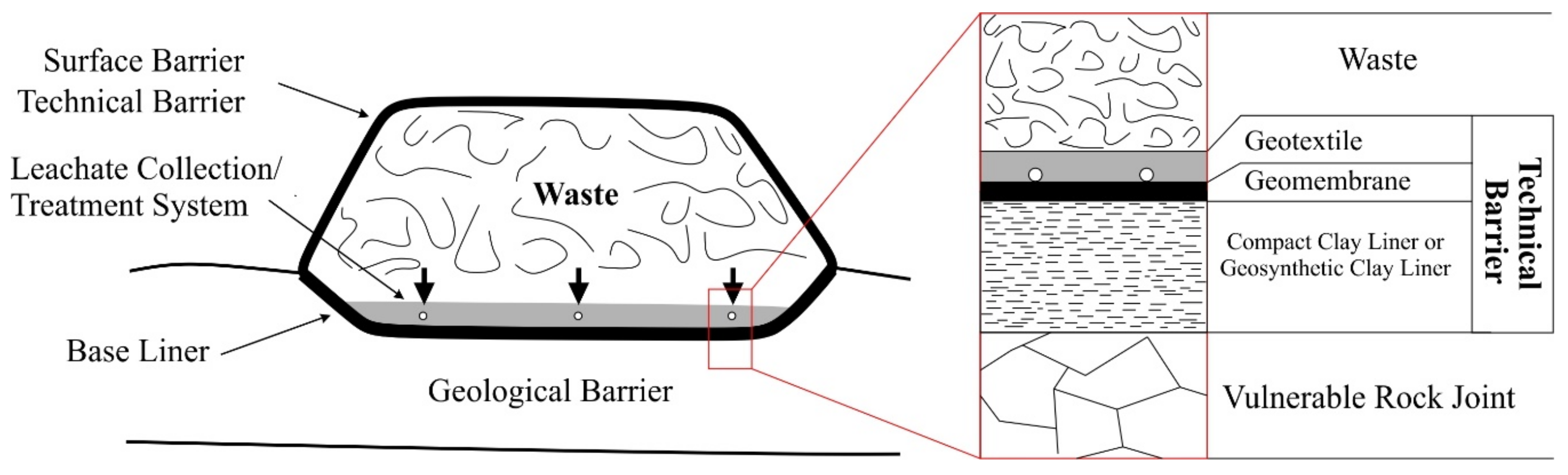
28]. The site should have a geomembrane added between the drainage layer and the clay liner layer as shown in
Figure 10, which can increase the security of the landfill. Moreover, geomembranes can prevent volumetric shrinkage which causes cracks that affect the engineering properties of the clay liner. However, the natural cover and liner need to be tested for the shrinkage limit, and compaction needs to be conducted on the dry side of the optimum moisture content due to the effect of volumetric shrinkage which causes cracks.

 ,
, 


