1. Introduction
As the development of industrial technology is changing to unmanned and automatic systems to improve productivity and competitiveness, the importance of motors, as a component part of the system, is gradually increasing. Among the various types of motors used in industrial facilities, small motors are actively being researched and developed to apply a gripper operated by motors in fields such as electronic parts assembly, medicine, human care, micro-moving structures, and military applications [
1,
2,
3,
4,
5]. Therefore, the demand for highly efficient and small motors, an essential part in the automation industry, is expected to increase. Also, it has become possible to manufacture precision small motors with high performance owing to the development in the material field, including a permanent magnet material and the advancement of precision processing and manufacturing technology. These motors are manufactured in various ways. For example, new actuator shapes have been developed using physical and chemical phenomena, such as electrostatic force, electromagnetic force, shape-memory alloy (SMA), smart polymers, and so on. Since some of these materials are difficult to control, there are limitations to using them. Therefore, we selected an electromagnetic motor, which is easy to manufacture and control and can easily calculate force. The typical gripper driving by electromagnetic force is composed of a motor and a reduction gear device for driving. The performance and size of the gripper is determined by an existing motor and reduction gear device. If the motor driving the gripper is too small, the desired torque will not be achieved due to the decreased motor size and subsequently weakened driving force due to the scaling effect. Thus, a reduction gear device is added to the small motor to generate the desired torque. The added reduction gear device increases the overall size of the small gripper, making it difficult to operate. In addition, the added reduction gear device may cause friction, mechanical backlash, or assembly errors, which may further cause malfunctions when it is operated. To avoid these problems, we selected a wobble motor because it is structurally simple and can generate a large torque due to the eccentric structure [
6,
7,
8,
9,
10].
The purpose of this study is to analyze the characteristics and optimal design of the wobble motor for a novel wobble gripper with the electropermanent magnet (EM). An existing wobble motor has the disadvantage that it cannot be fixed if the power is not supplied continuously. However, the EM can solve this problem. It is composed of neodymium (NdFeB) and semi-hard (Alnico5) magnets, and it can be used to fix or drive the wobble motor.
In order to analyze the characteristics of the wobble motor and the EM, it is necessary to predict the magnetic flux density and force generated by the electromagnet and the EM at the air gap. The most common method is to use commercial finite element software. However, since a number of iterative analyses are needed in the initial design step, this method is time-consuming and not systematic. Another method that is widely used in the initial design step is magnetic circuit analysis. With this method, it is necessary to know the magnetic flux density and magnetic force generated in the air gap between the rotor and the stator. Therefore, a magnetic circuit using the magnetic flux path of magnetic resistance is used. The method of calculating the magnetic flux density can be determined by calculation similar to the method of calculating the current in the electric circuit. However, such an analysis has limitations and can lead to erroneous results. This is because the leakage flux and fringing effects generated around the air gap are not considered, and it is difficult to accurately calculate these by including them in the magnetic circuit. Therefore, in this paper, we propose a simple method that can model the leakage flux and fringing effects of electromagnets as well as calculate the force generated by a rotating wobble motor using the distribution parameter method. The magnetic flux path consists of arcs and straight lines, and a rotating wobble was modeled with Cartesian coordinates in the distribution parameter method. The theoretical results, FEM analysis results, and experiments of prototypes of the wobble motor were confirmed. The schematic of a proposed novel gripper, the basic driving principle, basic structure and method to control the wobble motor and drive the proposed gripper, and the basic principle and structure of the EM are also presented in a straightforward manner.
2. Driving Principle and Theoretical Analysis
2.1. Driving Principle of a Wobble Motor
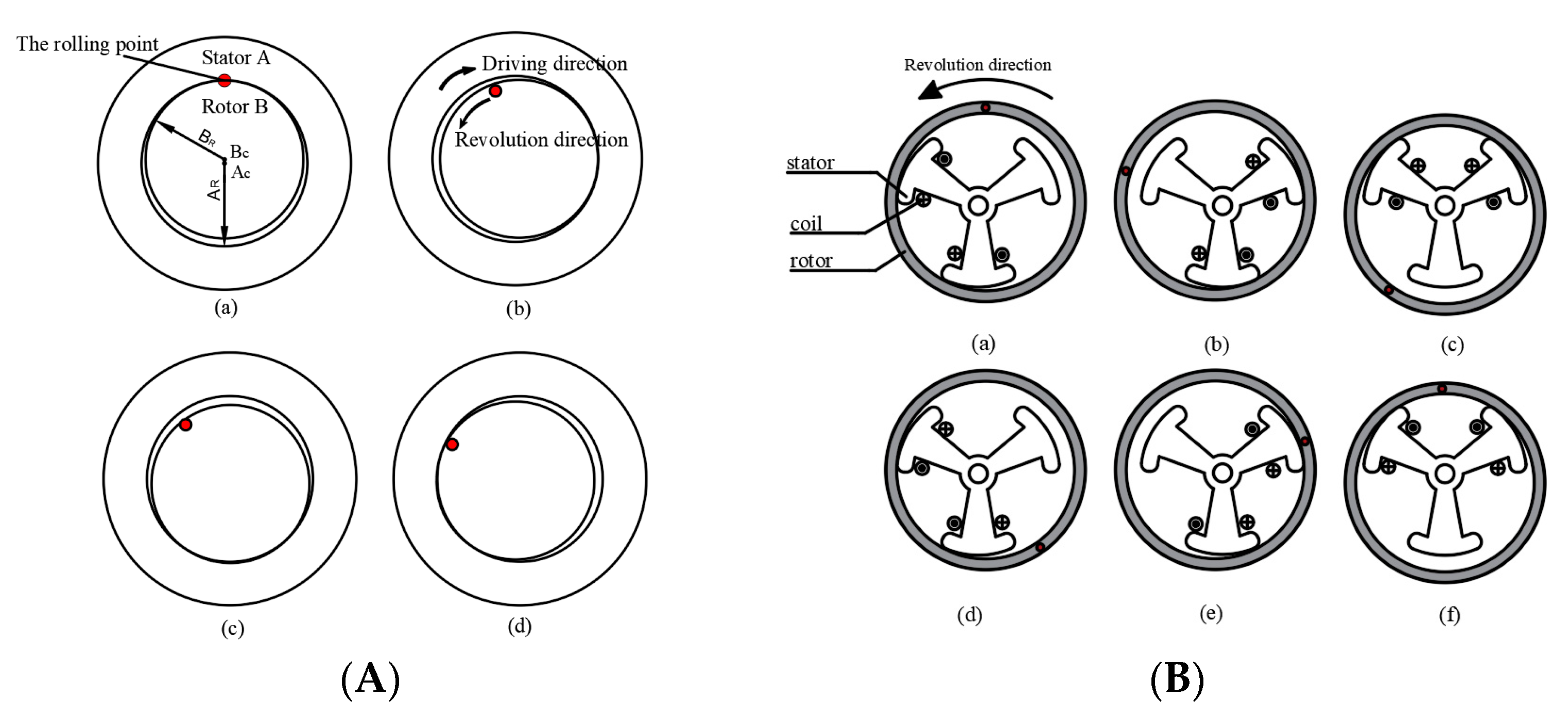
First, the basic driving principle of a wobble motor, which consists of cylindrical stator A and columnar rotor B, is presented in
Figure 1A.
,
,
, and
are shown in the central point of stator A, the central point of rotor B, the radius of stator A, and the radius of rotor B, respectively. The main feature of the wobble motor is the rolling of rotor B along stator A’s inner surface. If the current is supplied in a clockwise, continuous manner, the attractive force will be generated from the supplied current. The generated force from the stator pulls the rotor, and, as a result, the rotor can roll along the inner surface of the stator via the pulling force. The rolling motion of rotor B is in the opposite direction to the driving direction of stator A [
11,
12,
13,
14,
15,
16,
17,
18].
Figure 1A,B shows the operating principle of the wobble motor in the wobble gripper, which is composed of the stator and rotor. The inner rotor rotates as shown
Figure 1A, but the inner stator is fixed, and the external rotor rotates as shown
Figure 1B [
19,
20,
21].
When power is continuously supplied to the two coils inside the stator, they generate magnetic flux, thus producing attractive forces between the stator and rotor. The exterior rotor begins to rotate on the order of the supplied current. A complete cycle is shown, consisting of six electric phases.
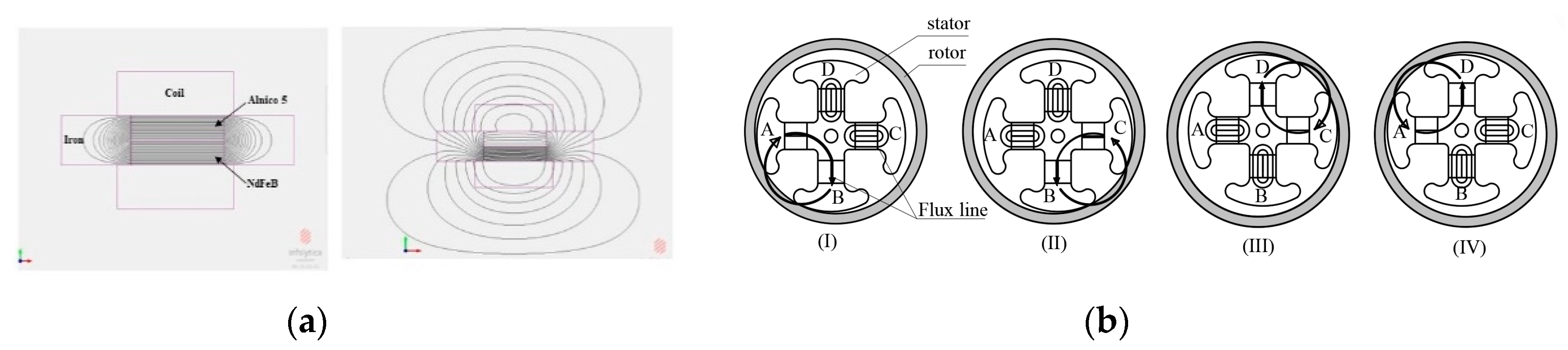
Second, the EM consists of two magnetic materials, a magnetically hard neodymium (NdFeB) type and another semi-hard type (Alnico5). These are wrapped with a coil as shown
Figure 2a. The EM was operated using MagNet of electromagnetic analysis software from Infolytica. If the magnetization directions of NdFeB and Alnico5 magnets are oppositely combined, the magnetic flux only circulates inside iron.
After Alinico5 was subjected to a current pulse of the opposite polarity, the magnetization directions of NdFeB and Alnico were the same, and EM generated an external magnetic flux as shown in
Figure 2a. The remnant flux density of Alnico 5 is approximately 1.2 T, and the normal coercivity is approximately 50 kA/m. The remnant flux density of NdFeB is approximately 1.2~1.3 T, and the normal coercivity is approximately 1000 kA/m [
22].
Figure 2b shows the driving principle of the wobble motor that can rotate and fix using an internal EM. As current is applied to the coil wound around the EM, the magnetization direction of the Alnico magnet is changed, as shown in
Figure 2b, the B pole magnetic flux flows from the A pole, and the C and D poles only flow inside the pole. After that, the wobble motor with the internal EM conducts two functions, namely ration and fixation, by applying the current, as in the basic principle of a wobble motor.
2.2. Theoretical Analysis of the Electropermanent Magnet
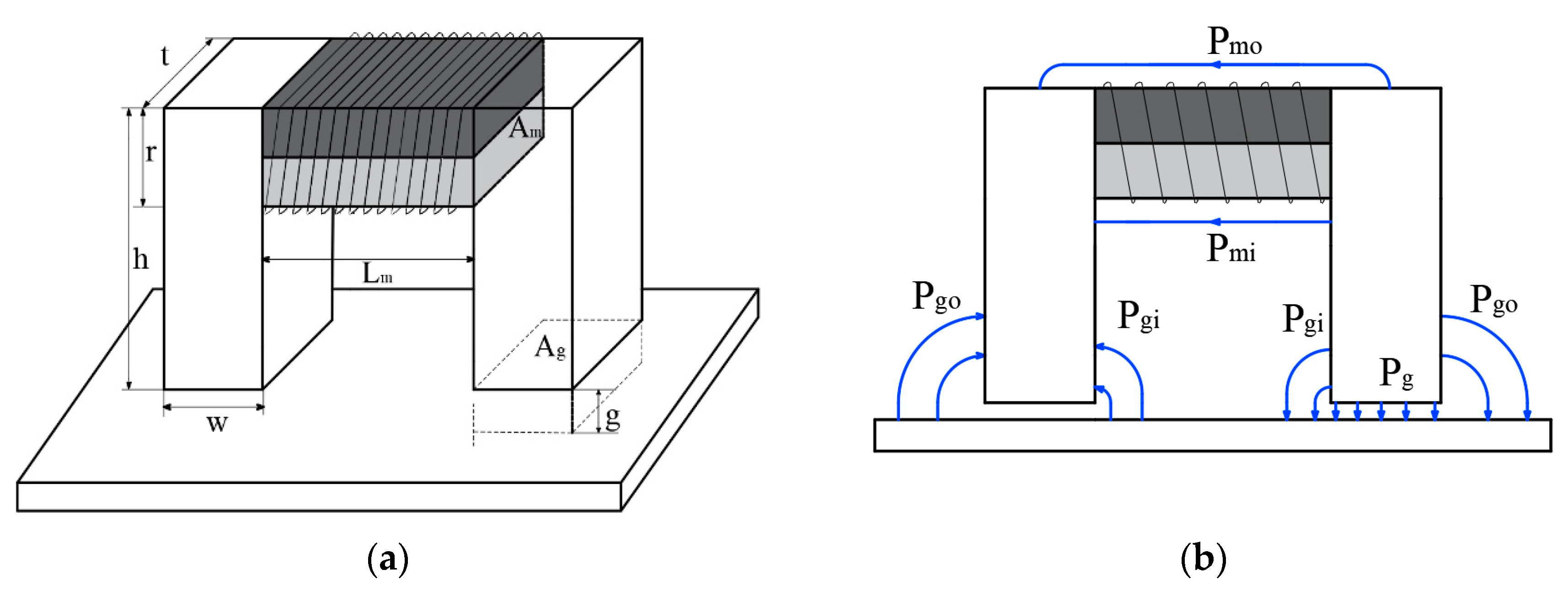
Figure 3a shows a schematic of an EM device for holding the proposed gripper.
Table 1 shows the specifications of the electromagnet elements in use, and Alnico and NdFeB magnets were replaced with cylindrical magnets instead of square magnets. In order to simplify calculations of the magnetic flux density, fringing flux was assumed as the leakage flux, and the path of the leakage flux was composed of a combination of arcs and straight line as shown
Figure 3b [
23]. As shown in
Figure 3b, the fringing magnetic fluxes are modeled by considering it as kind of leakage magnetic flux. It is also assumed that magnetic fluxes detouring on the right outside of the air gap are connected in a straight line with the quadrant and the length of the air gap [
24].
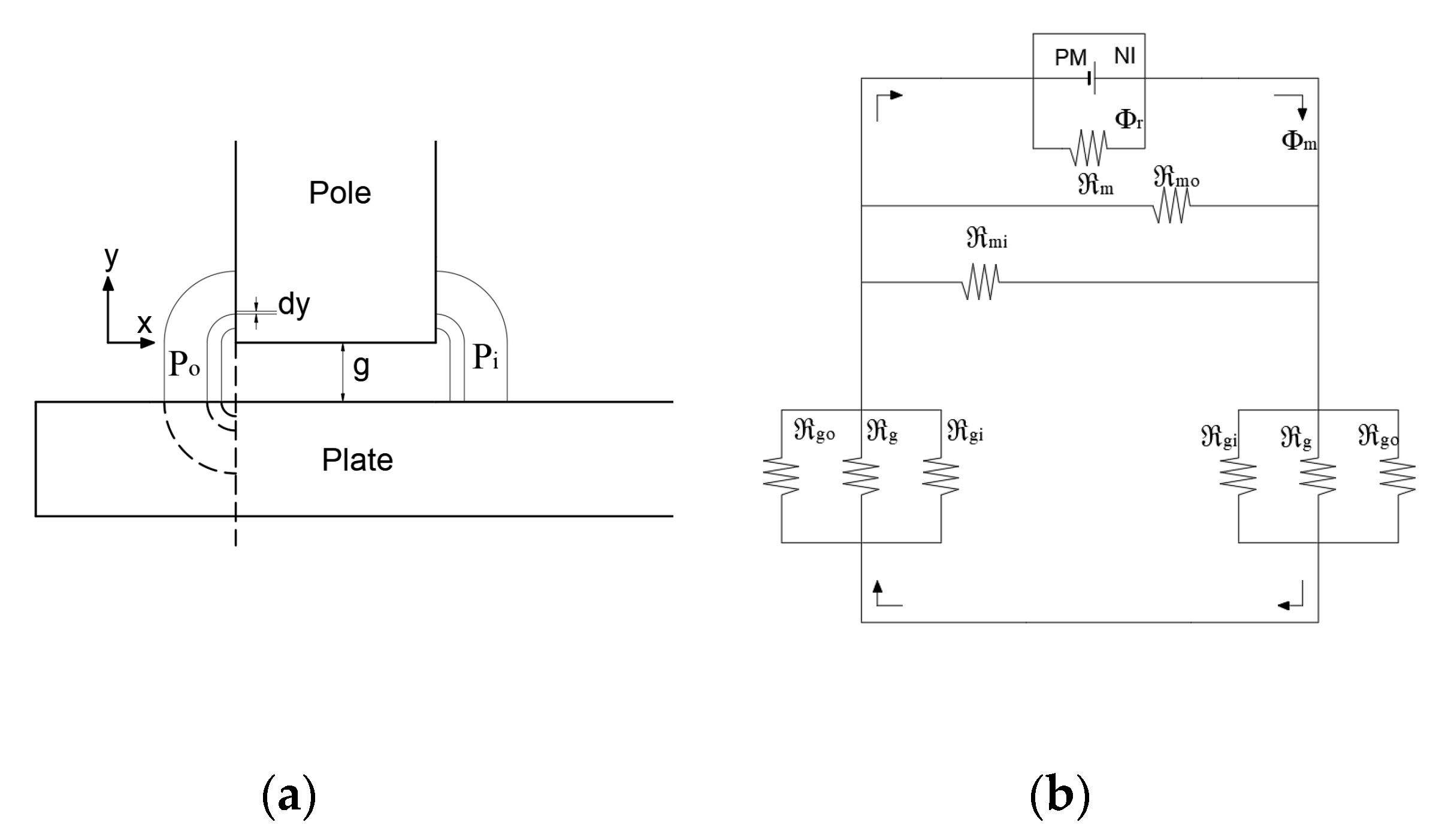
On the left of
Figure 4a, it is assumed that the leakage magnetic flux paths have the same quadrants, indicated by a solid line and dotted line, and a path is connected in a straight line along the length of the air gap. In order to calculate the magnetic flux of the gap, a permeance that is inverse to the magnetoresistance can be used. If each magnetic flux path has magnetoresistance, they can all be expressed as being connected in parallel. There are two assumptions here, namely that magnetic resistance in the iron core is ignored and there is no leakage magnetic flux and fringing effect. Therefore, the magnetic circuit can be represented as shown in
Figure 4b.
is resistance of the magnet.
is magnetic flux source.
is magnetic flux passing through the air gap. When permeability for each leakage magnetic flux path is defined as
and
, the reciprocal parameters can be expressed as magnetoresistance
and
.
The permeance
on the outside is shown in
Figure 4a.
The permeance in the path is as follows:
When the fringing effect is 10 times greater than the air gap, it is considered to be very small. Therefore, in this case, it was assumed that it was 10 times the air gap.
is assumed to be h/2,
of the path between the two cores is assumed to be (h − r)/2, and
are the paths bypassing the air with and without going through the core, respectively.
is the total magnetoresistance. The total Magnetic resistance, ignoring the magnetic resistance at the iron core, is as follows. The reciprocal of the permeance is the magnetic resistance for the magnetic flux path. Thus, all magnetic resistance in the circuit can be calculated.
To calculate the magnetic field generated in the air gap of the device fixed the gripper, we used a magnetic circuit and Gauss’ law [
13], which can be expressed as follows:
where
is the axial magnetic field intensity in the magnet.
and
are the Alnico5 and NdFeB magnets with axial magnetic flux density.
and
are the magnetic flux density in the air gap and the leakage permeance, respectively.
Ampere’s law is used to calculate the density of the air gap as follows:
Finally, the attractive force can be obtained by the Maxwell stress tensor, which can be written as:
2.3. Theoretical Analysis of the Wobble Motor
In order to obtain the magnetic flux density generated in the air gap of the wobble motor, the model was approximated as shown in
Figure 5 to avoid difficulties in analysis and to facilitate use of a linear coordinate system. The air gap is assumed to be very small with no fringing. Maxwell’s equation, magnetic vector potential
defined as
, and ohm’s law can be expressed as the distribution equation of the electromagnetic system. Their solutions have been well studied in other researchs [
25,
26,
27,
28]. Parameters w, p, g, h,
, and
are the pole width, pole pitch, air gap, thickness of the material, the permeability of air gap, and the permeability of the material, respectively. The pole pitch is
, where
is the number of poles.
In order to establish analytical solutions, variations in the r-direction are ignored, and
can also be assumed. The governing equation for the electromagnetic field is expressed as follows:
where
is the speed of the moving medium (m/s), and
is electrical conductivity (
).
where
and
are the wave number and angular velocity, respectively.
When current is suitably excited in the coil, the core creates waves traveling in the y-direction in the air gap.
The governing equation can be expressed as each layer.
In the air gap, the electrical conductivity is zero. In order to establish analytical solutions for the field distributions, the following assumptions are made: (1) the permeability of the yoke is infinite; (2) Variations in the r-direction are ignored, and the vector potential is directional and can be a function of x and y; (3) All layers extend to infinity in the -direction because the magnetic wheel is a rotary machine.
The solution for each layer can be written as
The flux density in the air gap is calculated using the following equation:
where
,
s is the slip, and
is the synchronous speed, which is equal to
when
s = 1.
The boundary conditions are as follows:
The magnetic flux density of the conductor can be obtained as
Finally, the electrodynamic force can be determined using Maxwell’s stress tensor, which can be written as
3. Modeling and Structure
3.1. Design and Control of the Proposed External Fixed Gripper
An existing of a wobble motor is limited in that it cannot be fixed if the power is not supplied continuously. Therefore, we propose a method to solve this difficulty using the external EM. It is shown in
Figure 6a, the proposed external gripper consists of an internal wobble motor that drives it and a fixed part with an EM to keep the proposed gripper’s movement constant.
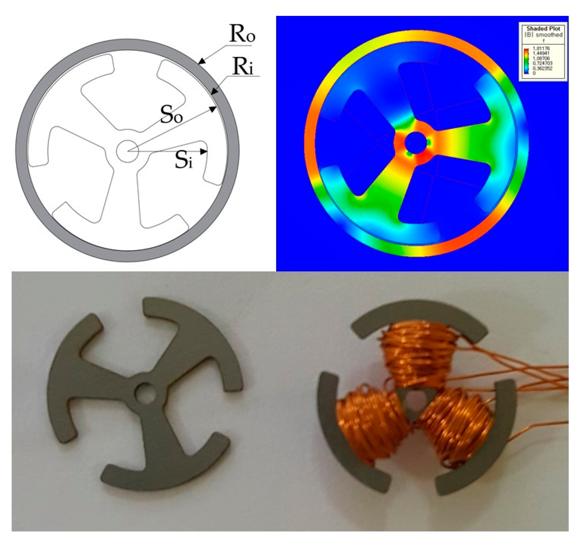
Figure 6b shows the shape of the core with three poles and four poles and the magnetic flux density distribution by FEM simulation. In this FEM analysis, the attractive force is obtained by exciting two coils when the rotor is momentarily in contact at the end of the stator. The schematic of an EM to fix the proposed gripper is represented in
Figure 6c, and each part has an Alnico magnet, an NdFeB magnet, and an iron pole with a coil wound around it. FEM simulation was performed to estimate the flux density distribution of the EM composed of NdFeB and Alnico5, each with 2 mm diameter and 2 mm length. In the initial conditions, when no current is present, the magnetization directions of NdFeB and Alnico5 are opposite. The magnetic flux line of the two magnets flows only towards the inside. This means that the rotation motion of the proposed gripper is unaffected by the EM. However, if Alnico is excited by the current to the opposite polarity, the magnetization direction of Alnico reversed. Therefore, the magnetization directions of NdFeB and Alnico are the same, which generates the external magnetic flux and attracts the proposed gripper. The results confirmed that the direction of the magnetic flux of the EM changed. Even if no current flowed through the coil, it could still remain fixed. The shape of the proposed gripper is shown
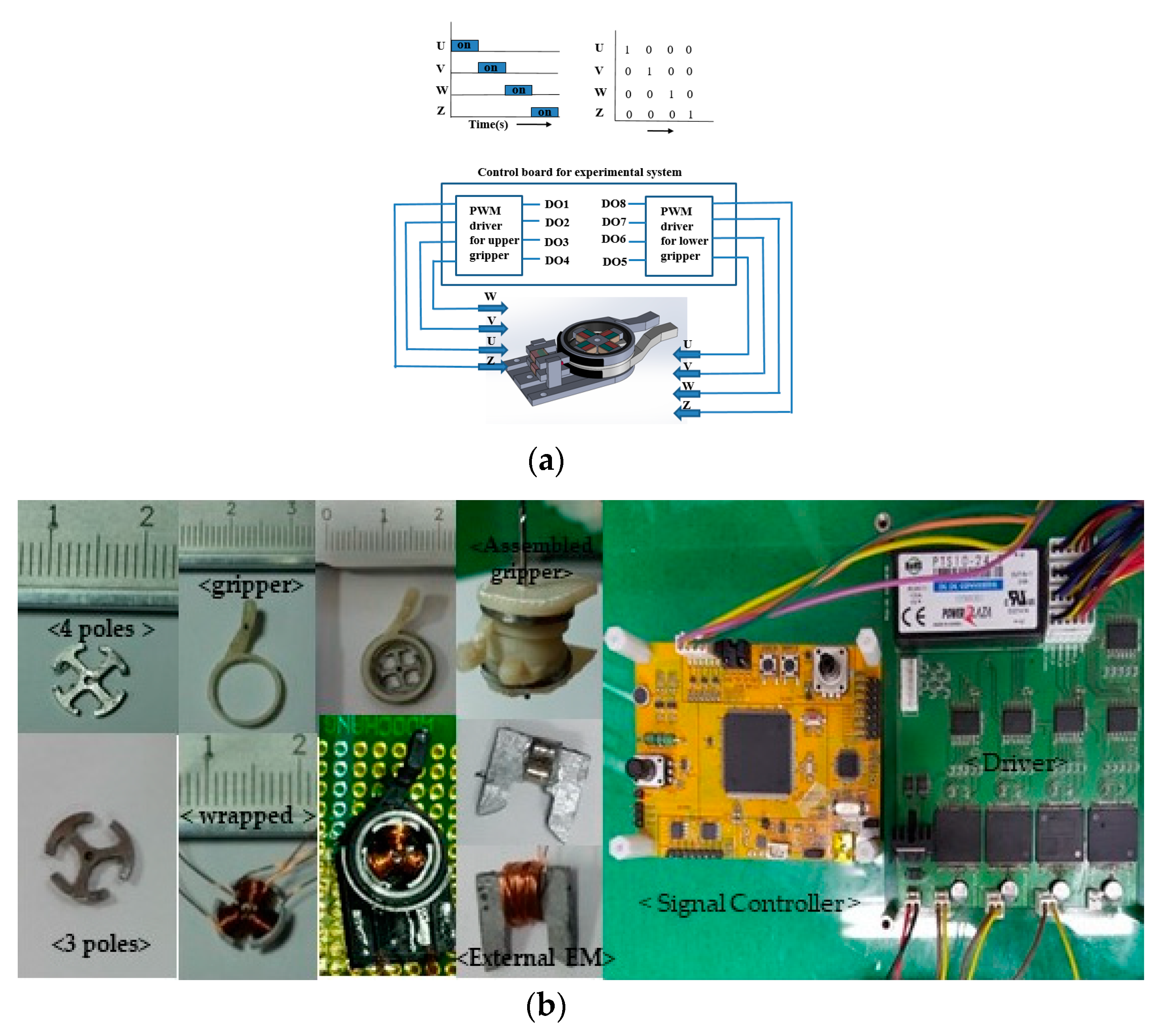
Figure 6d, and T, L, t, tg, te, and Rg are 2.5, 1.5, 0.5, 0.5, and 5.5 mm, respectively. The driving method of the proposed gripper and the coil excitation sequence to rotate the proposed gripper with four poles are represented in
Figure 7a. The rotational speed of the proposed gripper is controlled by the frequency of the signal controller.
The U, V, W, and Z at phase 4 matches with coil1, coil2, coil3, and coil4 wrapped around the core arm. The coil is excited as follows: (coil1 and coil2), (coil2 and coil 3), (coil 3 and coil 4), and (coil4 and coil 1). The three poles are driven in the same way as four poles, except for the Z signal. We fabricated the motor, the proposed gripper, and a prototype of the EM, and the core shape of the motor was fabricated with three poles and four poles using a computer numerical control (CNC) machine.
As shown
Figure 7b. The signal controller board was TMS320F28335, and the driver was directly manufactured to be used for both three-pole and four-pole cores. In order to change the magnetization direction of the EM, NI cRio-9022 from NATIONAL INSTRUMENTS and a typical-high performance motor driver were used.
Theory and Experimental Validation Results
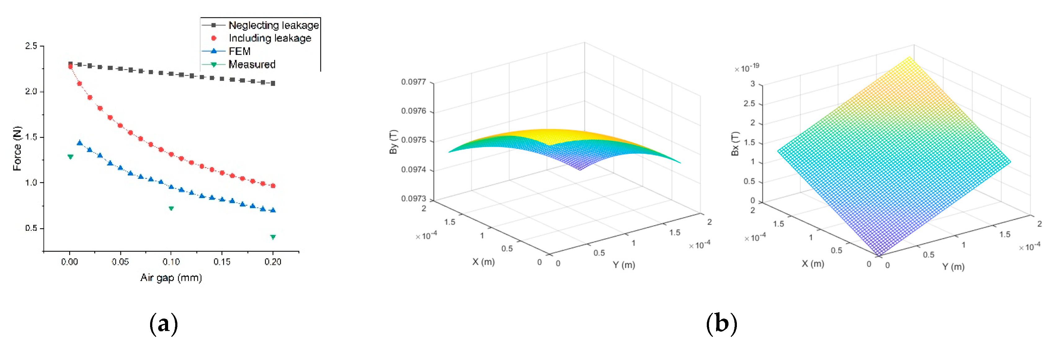
For the fixing wobble motor using the external EM,
Figure 8a summarizes results of FEM, the experiment, and modelling with and without leakage flux of the external EM while changing the air gap. When the air gap is 0.1 mm, the FEM result and the result of neglecting leakage flux shows an error as percentage of 130%, and the result of including leakage flux shows an error 38%. The experimental results show errors 31% and 80%, respectively when comparing the FEM result and the result of including leakage flux. When the internal wobble motor is applied 0.3 A at the 0.1 mm in air gap, the results show errors of 25%, 22%, and 8.5% in the three, four poles, and new material.
Figure 8b shows the flux density distribution in the x and y directions in the air gap. The variables from the three poles in
Table 2 are used.
Table 2 shows the specifications and results of the wobble motor and the new material. When 0.3 A was applied to the poles, the theoretical stall torque, considering flux leakage were also shown. The EM fabricated in
Figure 7b. a, b, t, lm, and r are 5, 5, 2, 2, and 6.1 mm, respectively. Both magnets are cylindrical and 2 mm in diameter.
The FEM and theoretical analyses confirmed that the performance of the proposed gripper depends on the core shape. The most important factor when designing the core is the electromagnetic force. The wider the cross-section from which the flux comes and the shorter the length of the core, the greater the generated electromagnetic force.
Therefore, considering the factors described above and the leakage magnetic flux, we further conducted FEM simulations by changing the core shape [
6].
As shown in
Figure 9, the optimized core shape was fabricated. Both dimensions are the same as the fabricated prototype with three poles. w is average value of the core width. To maximize the torque and minimize the losses, the core material was changed to electrical steel. The selected core material was 50PN350, characterized by Bsat = 1.62 T and core loss 3.50 watt per kilogram, from Pohang Iron and Steel Company (POSCO). The shape of the core was made by EDM (electro discharge machining).
3.2. Design and Control of the Proposed Internal Fixed Gripper
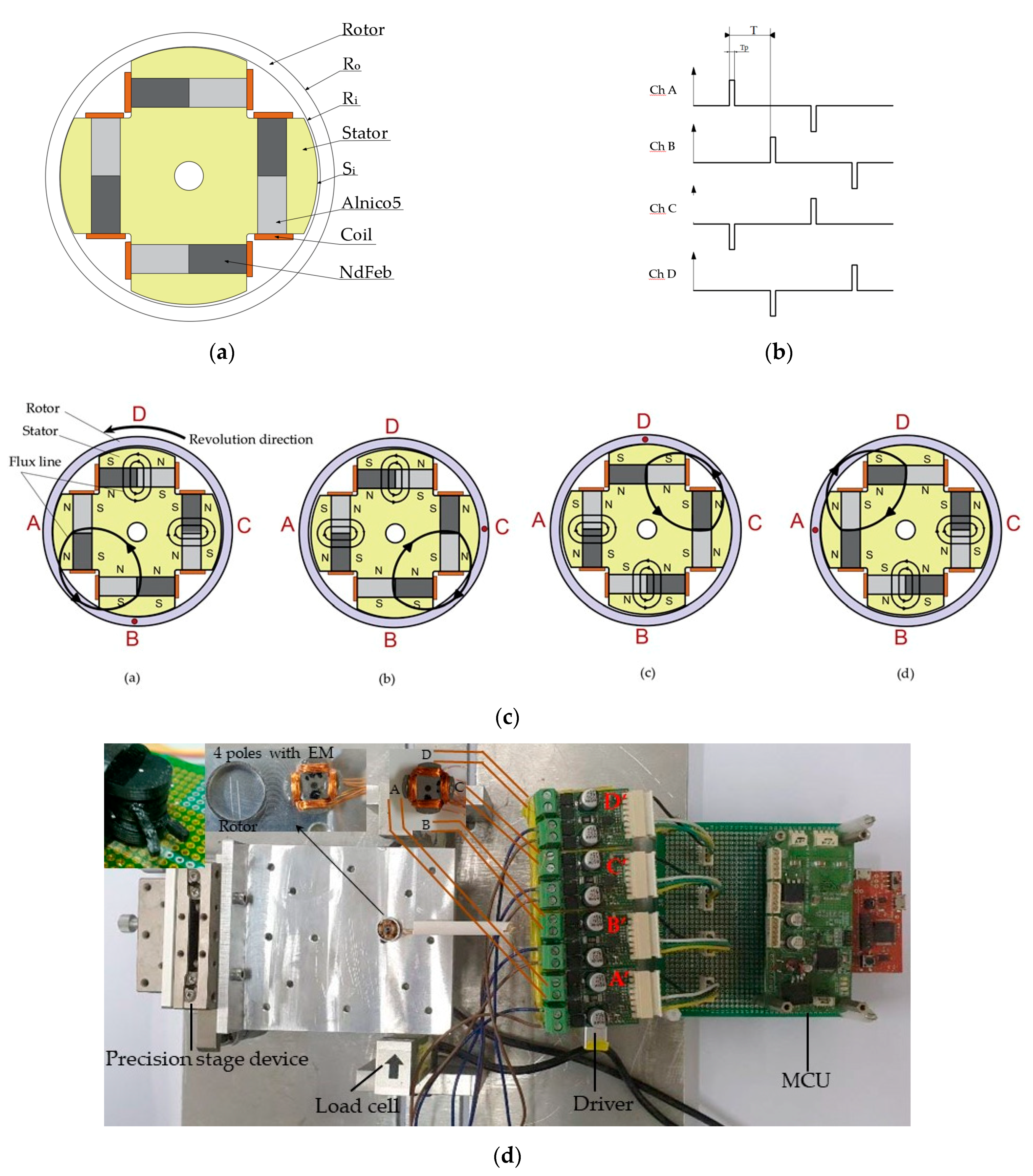
Figure 10a,b show the schematic of a wobble motor with an internal EM and a method of the control signal to change the magnetization direction of the EM. The driving sequence is controlled by the directly manufactured MCU.
Table 2 also shows the parameters of the wobble motor driven by an internal EM. To change the magnetization direction of the Alnico5 of the manufactured EM, a capacitor-type driver was used instead of the motor driver used in the previous experiment. The driving voltage was 35 V.
As shown in
Figure 10d, the A, B, C and D poles of wobble motor are connected the driver of A’ B’ C’, and D’.
Figure 10c shows how the wobble motor is driven. The magnetic flux flows from the B pole to A pole and pulls the rotor. when current is applied to the A and C poles as shown in
Figure 10c, the magnetic flux of the A pole flows only inside because the magnetization directions of the two magnets are opposite. The magnetic flux of the C pole flows outward, and the magnetic flux flows from the B pole to the C pole. The A, B, C, and D poles can change the polarity of the output according to the MCU signal, as shown
Figure 10b, in the driver operation sequence. Thus, the rotor rotates. As mentioned in the driving method, the wobble motor with the EM can be rotated or fixed by changing the polarity of the Alnico5 magnet.
Figure 10b shows the entire experimental setup, the internal stator with the EM coupled, and the assembled gripper. It is connected in the order of winding coils in the EM—A, B, C, and D—and can change the polarity of the output according to the MCU signal, as shown
Figure 8b in the driver operation sequence. The MCU required to drive the proposed gripper was directly manufactured and the drive voltage was 35 V. As mentioned in the driving principle, the gripper can be rotated or fixed by changing the polarity of the magnet using a capacitor-type driver.
Theory and Experimental Validation Results
Table 3 shows the parameters of the proposed gripper with the internal EM.
is pulse length, and the torque can be control by adjusting the pulse length. When the driving frequency is 25 Hz and
is 400 μs, the theoretical stall torques considering the flux leakage and FEM stall torque are 1.5 and 1.3 Nmm respectively. The experimental result was 0.8 Nmm. The experimental result shows an error of 87% and 62% in the theoretical result and the FEM result, respectively.
4. Conclusions
This paper presents a method that considers the leakage magnetic flux in increasing the accuracy of a circuit model, including the electromagnet and electro permanent magnet used in the method of driving and fixing the wobble motor for the proposed gripper. We also present a partial differential equation for the electromagnetic field, expressed as a continuous function over time and space using the distribution parameter method. In addition, the force generated by the wobble motor was calculated by approximating the model, in order to avoid difficulties in analysis and facilitate use of a linear coordinate system. As mentioned in the introduction, it is impossible to accurately present the leakage flux, but by assuming that the path of the leakage magnetic flux consists of a straight line and an arc, a reduction in error in the force generated, when the leakage magnetic flux was considered and not considered, was confirmed by comparing the FEM results and the experimental results. For the wobble motor with the external EM, comparing the result of including leakage flux and the FEM result, it is shown that the error is reduced from 38% to 13%. However, an error becomes large when the leakage flux is not considered. In the three poles of the internal wobble motor, the stall torque is increased from 230 μNm to 350 μNm through shape optimization using 50PN350 material. For the wobble motor with the internal EM, comparing the experimental result, the FEM result, and theoretical result, it is shown that there is a maximum error of about 87%. Theoretically, the torque is proportional to the square of the current, number of turns, and the shape. However, the loss of friction, fabricated losses, flux leak, and the hysteresis effect all affect the experimental measurements. The wobble motors have errors in the process of combining two magnets and manufacturing the core shape and rotor. Therefore, In the case of the EM coil wound and the core shape, the model needs significant improvement to manufacturing process, and if the air gap change can be expressed through geometrical functions, more accurate results can also be obtained. Also, this paper used 2D, but if the method is expanded to 3D then more accurate results can be obtained. However, in 3D analysis, the leakage path at the edge of the core is difficult to model, so the error will slightly increase. However, our study is useful in that, based on the results considering the leakage magnetic flux and the distribution parameter method, it not only contributes to the selection of initial design parameters necessary for FEM analysis in wobble motor designs, but the analysis results alone are meaningful as a basis for designing the wobble gripper. In this paper, we proposed an new and improved model with the EM of the existing wobble motor. The wobble motor is fixed from the outside, and the wobble motor can be fixed and rotated from the inside EM. Theoretical analysis of the EM and the wobble motor and the modeling of FEM provided a method to understand the driving principle and the theoretical results of the simplifying assumptions differing from experimental results, but they are compatible. If the theoretical model is elaborated by expanding to 3D with the air gap parameters, it is possibly more suitable than the existing wobble gripper design model. If it is possible to make a wobble motor with maximum holding force, it is more commercially suitable than the existing developed wobble motor. The proposed small gripper can be commercialized in various fields, such as assembly lines of industrial machinery, driving devices, grippers on small robots, and especially in the medical field.
Author Contributions
Conceptualization, designed the motor and gripper, and wrote the paper, S.Y.P.; contributed controller design, D.L.; analyzed the data and reviewed and the edited paper, B.S.; investigation and validation, S.Y.P., B.S., and D.L.; supervision and project administration, Y.S.B. All authors have read and agreed to the published version of the manuscript.
Funding
This research received no external funding.
Conflicts of Interest
The authors declare no conflict of interest.
References
- Samadikhoshkho, Z.; Zareinia, K.; Janabi-Sharifi, F. A Brief Review on Robotic Grippers Classifications. In Proceedings of the IEEE Canadian Conference of Electrical and Computer Engineering, Edmonton, AB, Canada, 5–8 May 2019. [Google Scholar]
- Shintake, J.; Cacucciolo, V.; Floreano, D.; Shea, H. Soft Robotic Grippers. Adv. Mater. 2018, 161, 1707035. [Google Scholar] [CrossRef] [PubMed]
- Zou, Y.; Cheung, N.C.; Pan, J.F. An Adaptive High-Precision Tracking Controller for the Coupled Switched Reluctance Two-Finger Gripper. IEEE Trans. Magn. 2015, 15, 1–4. [Google Scholar] [CrossRef]
- Ullrich, F.; Dheman, K.S.; Schuerle, S.; Nelson, B.J. Magnetically Actuated and Guided Milli-Gripper for Medical Applications. In Proceedings of the IEEE International Conference on Robotics and Automation, Seattle, WA, USA, 26–30 May 2015; pp. 1751–1756. [Google Scholar]
- Hwang, D.; Higuchi, T. A Planar Wobble Motor with a XY Compliant Mechanism Driven by Shape Memory Alloy. IEEE/ASME Trans. Mechatron. 2016, 21, 302–315. [Google Scholar] [CrossRef]
- Nagata, T.; Suzumori, K.; Kanda, T.; Uzuka, K.; Enomoto, I. Electro Direct-Drive Stepping Motor for Robots. In Proceedings of the IEEE International Conference on Robotics and Automation, New Orleans, LA, USA, 26 April–1 May 2004; pp. 4493–4498. [Google Scholar]
- Suzumori, K.; Hori, K.; Miyagawa, T. A Direct-Drive Pneumatic Stepping Motor for Robots: Designs for Pipe-Inspection Microrobots and for Human-Care Robots. In Proceedings of the IEEE International Conference on Robotics and Automation, New Orleans, LA, USA, 26 April–1 May 2004; pp. 3047–3052. [Google Scholar]
- De cristofaroa, S.; Stefaninia, C.; Ngpaka, N.; Susiloa, E. Electromagnetic wobble micromotor for microrobots actuation. Sens. Actuators A Phys. 2010, 161, 234–244. [Google Scholar] [CrossRef]
- Trimmer, W.; Jebens, R. An operational harmonic electrostatic motor. In Proceedings of the IEEE Micro Electro Mechanical Systems, Proceedings, An Investigation of Micro Structures, Sensors, Actuators, Machines and Robots, Salt Lake City, UT, USA, 20–22 February 1989; pp. 13–16. [Google Scholar]
- Miyake, M.; Suzumori, K.; Uzuka, K. Development of a Thin Electromagnetic Wobble Motor. In Proceedings of the IEEE International Conference on Robotics and Biomimetic, Karon Beach, Thailand, 7–11 December 2011; pp. 2523–2528. [Google Scholar]
- Jacobsen, S.C.; Price, R.H.; Wood, J.E.; Rytting, T.H.; Rafaelof, M. The wobble motor: Design, fabrication and testing of an eccentric-motion electrostatic microactuator. In IEEE International Conference on Robotics and Automation; IEEE Computer Society: Scottsdale, AZ, USA, 1989. [Google Scholar]
- Jacobsen, S.C.; Price, R.H.; Wood, J.E.; Rytting, T.H.; Rafaelof, M. The wobble motor: An electrostatic, planetary-armature, microactuator. In Proceedings of the Micro Electro Mechanical Systems, Salt Lake City, UT, USA, 20–22 February 1989. [Google Scholar]
- Jungreis, A.M.; Kelley, A.W. The axial air gap wobble motor—an appropriate topology for magnetic micromotors. In Proceedings of the 13th IAS Annual Meeting, IAS’95, Conference Record of the Industry Applications Conference, Orlando, FL, USA, 8–12 October 1995. [Google Scholar]
- Mehergancy, M.; Nagarkar, P.; Senturia, S.D.; Lang, J.H. Operation of Microfabricated Harmonic and Ordinary Side-Drive Motors. In Proceedings of the IEEE Proceedings on Micro Electro Mechanical Systems, Napa Valley, CA, USA, 11–14 February 1990. [Google Scholar]
- Dhuler, V.R.; Mehregany, M.; Phillips, S.M. An experimental technique and a model for studying the operation of harmonic side-drive micromotors. IEEE Trans. Electron Device 1993, 40, 1977–1984. [Google Scholar] [CrossRef]
- Deng, K.; Meheregany, M. Outer-rotor polysilicon wobble micromotors. In Proceedings of the IEEE Workshop on Micro Electromechanical Systems, Oiso, Japan, 25–28 January 1994. [Google Scholar]
- Furuhata, T.; Hirano, T.; Lane, L.H.; Fontana, R.E.; Fan, L.S.; Fujita, H. Outer rotor surface-micromachined wobble micromotor. In Proceedings of the IEEE Micro Electro Mechanical Systems, Fort Lauderdale, FL, USA, 10 February 1993. [Google Scholar]
- Suzumori, K.; Hori, K. Micro electrostatic wobble motor with toothed electrodes. In Proceedings of the Micro Electro Mechanical Systems, Proceedings IEEE Tenth Annual International Workshop, Nagoya, Japan, 26–30 January 1997; pp. 227–232. [Google Scholar]
- D’Attanasio, S.; Lazzarini, R.; Stefanini, C.; Carrozza, M.C.; Dario, P. A one cubic centimeter mobile microrobot with a steering control. In Proceedings of the 1997 IEEE/RSJ International Conference on Intelligent Robot and Systems, Grenoble, France, 11 September 1997; pp. 1318–1324. [Google Scholar]
- Dario, P.; Carrozza, M.C.; Stefanini, C.; D’Attanasio, S. A mobile microrobot actuated by a new electromagnetic wobble micromotor. IEEE/ASME Trans. Mechatron. 1998, 3, 9–16. [Google Scholar] [CrossRef]
- Stefanini, C.; Carrozza, M.C.; Dario, P. A mobile microrobot driven by a new type of electromagnetic micromotor. In Proceedings of the IEEE Seventh International Symposium on Micro Machine and Human Science, Nagoya, Japan, 2–4 October 1996. [Google Scholar]
- Campbell, P.; Al-Murshid, S. A model of anisotropic Alnico magnets for field Computation Magnetics. IEEE Trans. Magn. 1982, 18, 898–904. [Google Scholar] [CrossRef]
- Hanselman, D.C. Brushless Permanent Magnet Motor Design; McGraw-Hill: New York, NY, USA, 1994. [Google Scholar]
- Roters, H.C. Electromagnetic Devices, 1st ed.; John Wiley & Sons: New York, NY, USA, 1941. [Google Scholar]
- Yamamura, S. Theory of Linear Induction Motors, 2nd ed.; Wiley: New York, NY, USA, 1979. [Google Scholar]
- Wangsness, R.K. Electromagnetic Fields, 2nd ed.; Wiley: New York, NY, USA, 1986. [Google Scholar]
- Griffiths, D.J. Introduction to Electrodynamics, 2nd ed.; Prentice Hall: New Jersey, NJ, USA, 1989. [Google Scholar]
- Nasar, S.A. Linear Motion Electric Machines; John Wiley & Sons: New York, NY, USA, 1976. [Google Scholar]
| Publisher’s Note: MDPI stays neutral with regard to jurisdictional claims in published maps and institutional affiliations. |
© 2020 by the authors. Licensee MDPI, Basel, Switzerland. This article is an open access article distributed under the terms and conditions of the Creative Commons Attribution (CC BY) license (http://creativecommons.org/licenses/by/4.0/).


