Article

Evaluation of a Combustion-Based Mesoscale Thermal Actuator in Open and Closed Operating Cycles †

by
Sindhu Preetham Burugupally
Department of Mechanical Engineering, Wichita State University, Wichita, KS 67260, USA
This paper has a preprints version which has been not sent for peer review.
Actuators 2019, 8(4), 73; https://doi.org/10.3390/act8040073
Submission received: 2 September 2019 / Revised: 19 October 2019 / Accepted: 19 October 2019 / Published: 23 October 2019

Abstract

:
A combustion-based mesoscale thermal actuator is proposed and its performance is studied in both open and closed cycle operations using a physics-based lumped-parameter model. The actuator design is unique as it implements a free-piston complaint architecture where the piston is free to move in a linear direction. Our objective is to study the actuator behavior in both the cycles to help identify the benefits and highlight the differences between the two cycles. The actuator is modeled as a spring-mass-damper system by taking an air standard cycle approach. Three observations are reported: (1) for nominal heat inputs (140 J/cycle), the actuator can produce large displacement strokes (16 cm) that is suitable for driving mesoscale robots; (2) the efficiency of the actuator depends on the heat input; and (3) for a specific heat input, both the open and closed cycles operate differently—with different stroke lengths, peak pressures, and thermal efficiencies. Our study reveals that the performance metrics of the actuator make it an ideal candidate for high speed, large force, and large displacement stroke related applications.

1. Introduction

Mechanical actuation via thermal actuators is a topic of interest due to their ability to generate forces O ( 10 1 ) N and displacement strokes O ( 10 4 ) m at mesoscale (millimeter) regime [1]. Most thermal actuators employ either bimorph [2], solid expansion [3], fluid expansion [4], state change (liquid-to-vapor) [5], gas expansion/compression [6], or combustion-based mechanisms [7]. Among them, state change and combustion-based mechanisms are found to be suitable for large displacement and force generation at mesoscale as they benefit from the scaling laws of physics [5,7]. In particular, combustion-based miniature heat engines offer high power density to weight ratio and fast response, thus making them ideal for applications that require high speed, large force, and large displacement strokes.
Unfortunately, thermal actuators or heat engines with sliding-piston architecture at mesoscale suffer from high friction, leakage, and heat losses, resulting in poor thermal efficiencies [8]. A method to improve the thermal efficiency is by eliminating the crankshaft assembly and associated friction losses [7,9,10]; this can be accomplished by implementing a flexible or compliant architecture (Figure 1) instead of a sliding-piston architecture. This approach offers several advantages such as no leakage losses, simpler construction, and lower fabrication costs. Research on the fundamental design of thermal actuators (heat addition/rejection cycle [7]) or heat engines (Otto cycle) [9,10] that employ compliant architecture are being studied through models [10], prototype fabrication, and experiments [9]. Realization of such an actuator will require materials that can sustain the pressures, temperatures, and elastic deformations that are encountered in practical applications. Candidate designs include bellows and other super compliant structures fabricated from metals and composites [11]. First-principle based mathematical models are being developed to assess the performance of the compliant actuators/engines for a range of physical and operating parameters in both open and closed cycle operations. However, it is unclear whether such a combustion-based thermal actuator be analyzed or designed to operate in an open or a closed cycle.
Our present work on thermal actuators builds on our prior physics-based modeling efforts of a resonant heat engine for portable power applications [7,9,10]. Our previous work includes the design, prototyping, and characterization of a flexible mesoscale engine that employs metal bellows instead of a traditional piston-cylinder assembly [12]. In this study, through a physics-based lumped-parameter model, similar to our previously developed models on free piston engines [13,14,15], we will investigate the behavior and performance of a mesoscale thermal actuator using a spring-mass-damper analogy and taking an air standard cycle approach. Here, using the model, we will predict the actuator performance for a range of operating conditions and report on the important differences between the open and closed cycle operations. The proposed actuator can be employed to charge an air tank that is intended to serve as a portable pneumatic energy source for a wide range of applications including exoskeleton [16], locomotion [17], and rehabilitation [18]. Our study will show that the proposed actuator offers a one order of magnitude higher energetic merit than the current portable power sources and actuation systems such as chemical batteries coupled with electric motors.

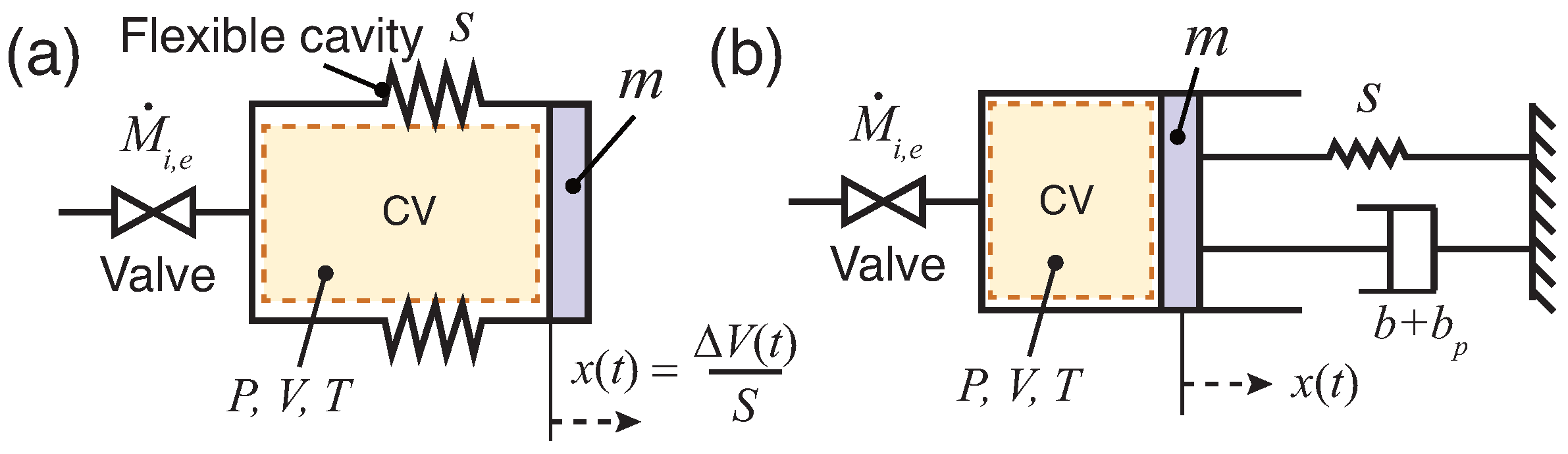
2. Thermal Actuator: Design and Model

The proposed actuator is similar to a traditional internal combustion engine, where fuel-air mixture is burnt in a piston-cylinder arrangement to produce force and displacement strokes. The actuator comprises of a flexible cavity with a piston attached at one end (Figure 1a). The flexible or compliant architecture reduces the frictional losses by up to 5% [9,10]. The actuator can be operated in both open and closed cycles. The actuator when operated in the open cycle comprises of compression ( 1 2 ), heat addition ( 2 3 ), expansion ( 3 4 ), exhaust ( 4 5 6 ), and intake ( 6 7 1 ) processes as depicted in Figure 2. Unlike the open cycle, the closed cycle terminates with the heat rejection process ( 4 1 ). In the open cycle, the actuator exchanges both heat and mass with the surroundings, while in the closed cycle only exchange of heat takes place.
A physics-based model is derived to investigate the actuator behavior and performance for both the open and closed cycle operations. The actuator is modeled as a spring-mass-damper system by taking an air standard cycle approach [19] (Figure 1b). The hollow cavity represents the control volume CV and contains the working fluid (air). The combustion process is modeled as a constant volume heat addition process to CV for a short duration t q 0 and the heat rejection at the end of the expansion process is modeled as a mass transfer process (for open cycle) or by applying a cooling pulse (for closed cycle) for a short duration t q 0 (Figure 3). The compliant cavity CV has a nominal volume V o given by V o = L S , where L is the nominal cavity length and S is the cross-sectional area of the cavity. The cavity has a stiffness s which allows horizontal displacement x ( t ) of the piston m. Damper b models energy conversion which is the sum of both friction work and useful work by the actuator, and b p (<0) models work done on the actuator during the intake process. Over an operating cycle, the working fluid temperature, T o + Δ T ( t ) , pressure, P o + Δ P ( t ) , and cavity volume, V o + Δ V ( t ) undergo cyclic variation, where ‘o’ subscript represents nominal or ambient conditions, while Δ represents time-dependent excursion.
The actuator model Equations (1)–(5) is derived by employing the Newton’s second law of motion, conservation of mass, conservation of energy, an ideal gas model, and a linear mass flow-rate equation.
m S 2 Δ V ¨ + b + b p S 2 Δ V ˙ + s S 2 Δ V = Δ P
M ˙ = M i ˙ M e ˙
h Δ T + d M c v T d t + P Δ V ˙ = q + M i ˙ c p T i M e ˙ c p T
P V = M R T
M ˙ i , e = k Δ P
where M is the working fluid (air) mass, h is the total heat loss coefficient, R is the mass-specific gas constant of air, k is the mass flow rate coefficient, and c v and c p are the constant volume and constant pressure heat capacities of air. The overdot denotes time derivative, while the subscripts ‘i’ and ‘e’ denote intake and exhaust processes, respectively. The model Equations (1)–(5) is nondimensionalized using the scaling terms given in Equation (6) and then written in a state space format as shown in Equations (7)–(10).
Δ V ¯ = Δ V V o , Δ P ¯ = Δ P P o , Δ T ¯ = Δ T T o , q ¯ = q q H , and t ¯ = t ω
d Δ V ¯ d t ¯ = Δ V ¯ ˙
d Δ V ¯ ˙ d t ¯ = Δ P ¯ γ b + b p m ω Δ V ¯ ˙ s m ω 2 Δ V ¯
Δ T ¯ ˙ = 1 M c v T o ω q + M ˙ i T o R + c p Δ T ¯ i c v Δ T ¯ h T o Δ T ¯ M ˙ e R T o 1 + Δ T ¯ P o V o ω 1 + Δ P ¯ Δ V ¯ ˙
Δ P ¯ ˙ = 1 P o V o ω 1 + Δ V ¯ M ˙ i M ˙ e R T o 1 + Δ T ¯ + M R T o ω Δ T ¯ ˙ P o V o ω 1 + Δ P ¯ Δ V ¯ ˙
where ω = γ P o S 2 m V o is a reference frequency, γ = 1.4 is specific heat ratio of the working fluid (air), and the overbar denotes a nondimensional term.

2.1. Solving the Open Cycle Model

To generate a pressure-volume diagram, the model Equations (7)–(10) is numerically integrated in the order 1→2→3→4→5 →6→7→1 (Figure 2) starting with state 1: Δ V ¯ 1 , Δ P 1 ¯ , Δ T 1 ¯ , Δ V 1 ¯ ˙ = 0 . The resulting volume Δ V 2 ¯ , pressure Δ P 2 ¯ , and temperature Δ T 2 ¯ from the compression process, 1→2 is computed by integrating Equations (7)–(10) from the initial condition Δ V 1 ¯ , Δ P 1 ¯ , Δ T 1 ¯ , Δ V 1 ¯ ˙ = 0 for a time t ¯ 1 such that the piston velocity V 2 ¯ ˙ = 0 . The resulting volume Δ V 3 ¯ , pressure Δ P 3 ¯ , and temperature Δ T 3 ¯ during the heat addition process, 2→3 is computed from Equations (8) and (9) by assuming it to be instantaneous ( Δ V 3 ¯ = Δ V 2 ¯ and Δ V 3 ¯ ˙ = Δ V 2 ¯ ˙ ). The volumes, pressures, and temperatures Δ V 4 ¯ , Δ P 4 ¯ , Δ T 4 ¯ ; Δ V 6 ¯ , Δ P 6 ¯ , Δ T 6 ¯ ; and Δ V 1 ¯ , Δ P 1 ¯ , Δ T 1 ¯ from the expansion 3→4, exhaust (displacement phase) 5→6, and intake processes 6→7→1 are computed by integrating Equations (7)–(10) from the initial conditions Δ V 3 ¯ , Δ P 3 ¯ , Δ T 3 ¯ , Δ V 3 ¯ ˙ = 0 ; Δ V 5 ¯ , Δ P 5 ¯ , Δ T 5 ¯ , Δ V 5 ¯ ˙ = 0 ; and Δ V 6 ¯ , Δ P 6 ¯ , Δ T 6 ¯ , Δ V 6 ¯ ˙ = 0 for times t ¯ 2 , t ¯ 3 , and t ¯ 4 respectively such that the piston velocity Δ V 4 ¯ ˙ = Δ V 5 ¯ ˙ = 0 and Δ V 6 ¯ ˙ = Δ V 7 ¯ ˙ = 0 . The times t ¯ 1 , t ¯ 2 , t ¯ 3 , and t ¯ 4 are unknowns and are determined during the process of integration. The blowdown process 4→5 is assumed instantaneous, isentropic, and occurs at zero piston velocity ( Δ V 4 ¯ ˙ = Δ V 5 ¯ ˙ = 0 ) and ambient pressure ( Δ P 5 ¯ = 0 ). The working fluid temperature at state 5, Δ T ¯ 5 is determined using the adiabatic relation:
Δ T ¯ 5 = 1 + Δ T ¯ 4 1 + Δ P ¯ 4 1 + Δ P ¯ 5 1 γ γ 1

2.2. Solving the Closed Cycle Model

To generate a pressure-volume diagram, the model Equations (7)–(10) is numerically integrated in the order 1→2→3→4→1 (Figure 2) starting with state 1: Δ V ¯ 1 , Δ P 1 ¯ , Δ T 1 ¯ , Δ V 1 ¯ ˙ = 0 . The resulting volume Δ V 2 ¯ , pressure Δ P 2 ¯ , and temperature Δ T 2 ¯ from the compression process, 1→2 is computed by integrating Equations (7)–(10) from the initial condition Δ V 1 ¯ , Δ P 1 ¯ , Δ T 1 ¯ , Δ V 1 ¯ ˙ = 0 for a time t ¯ 1 such that the piston velocity V 2 ¯ ˙ = 0 . The resulting volume Δ V 3 ¯ , pressure Δ P 3 ¯ , and temperature Δ T 3 ¯ during the heat addition process (2→3) is computed from Equations (8) and (9) by assuming it to be instantaneous ( Δ V 3 ¯ = Δ V 2 ¯ and Δ V 3 ¯ ˙ = Δ V 2 ¯ ˙ ). The volume, pressure, and temperature Δ V 4 ¯ , Δ P 4 ¯ , Δ T 4 ¯ from the expansion process 3→4 is computed by integrating Equations (7)–(10) from the initial conditions Δ V 3 ¯ , Δ P 3 ¯ , Δ T 3 ¯ , Δ V 3 ¯ ˙ = 0 for time t ¯ 2 such that the piston velocity Δ V 4 ¯ ˙ = Δ V 1 ¯ ˙ = 0 . The times t ¯ 1 and t ¯ 2 are unknowns and are determined during the process of integration. The heat rejection process 4→1 is assumed to be instantaneous and occurs at zero piston velocity ( Δ V 4 ¯ ˙ = Δ V 1 ¯ ˙ = 0 ).

3. Results and Discussion

The actuator with h = 0 W/K, b = 21.5 N-s/m, k = 6.8 × 10 7 kg/s-Pa ± 20%, V o = 21.8 cc, s = 3050 N/m, m = 0.18 kg, and clearance volume V c =0.01 V o are treated as the reference. These numerical values are experimentally determined [9,10]. T o = 295 K and P o = 93.4 kPa are the ambient and standard conditions.

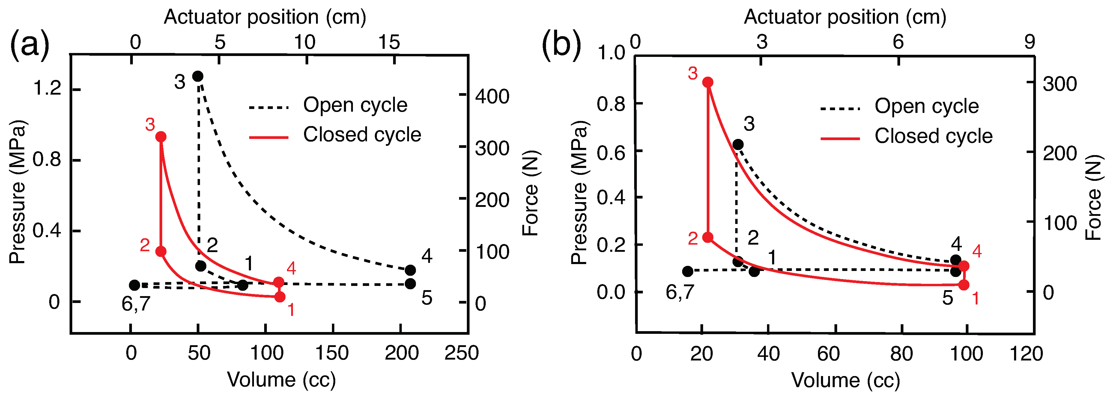
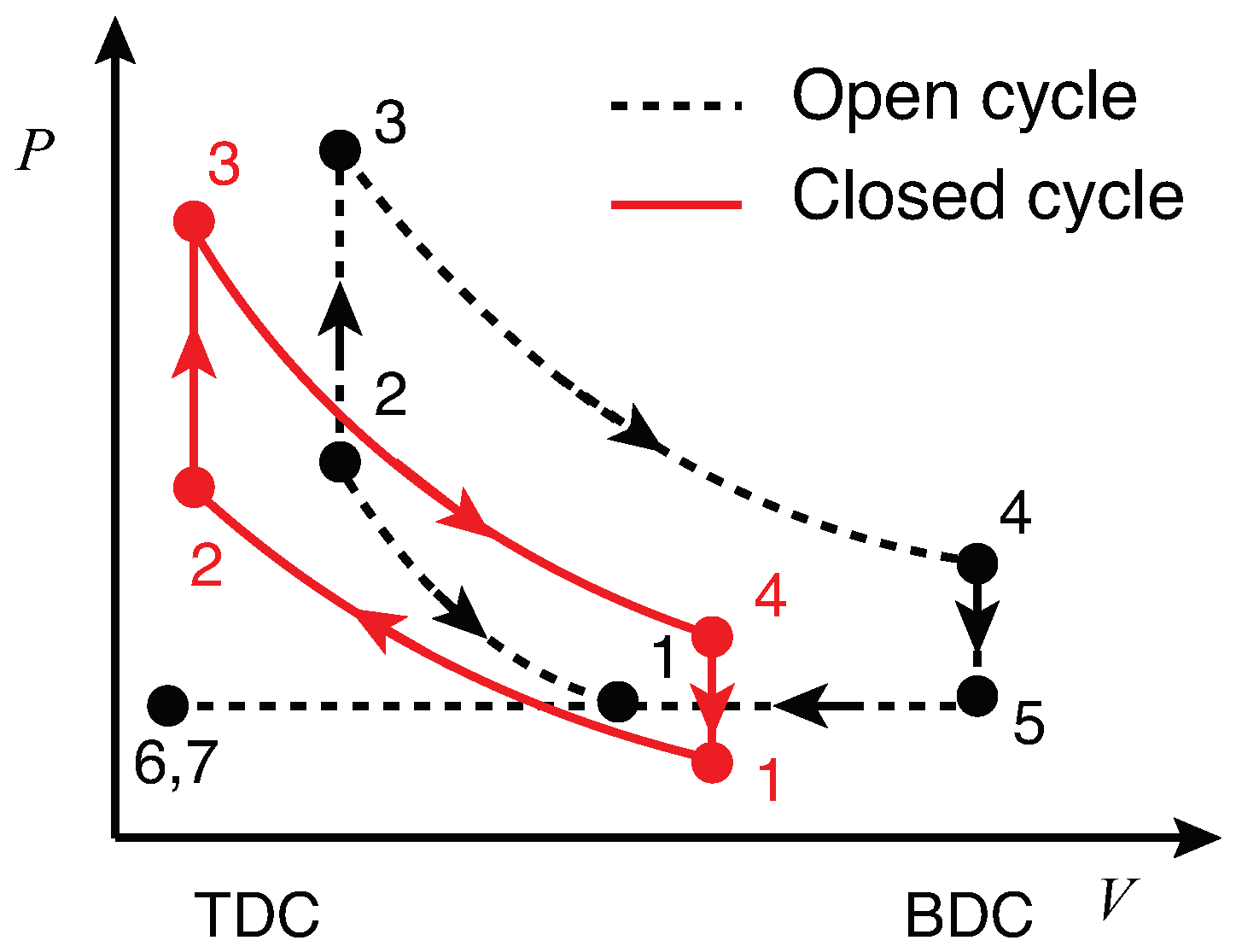
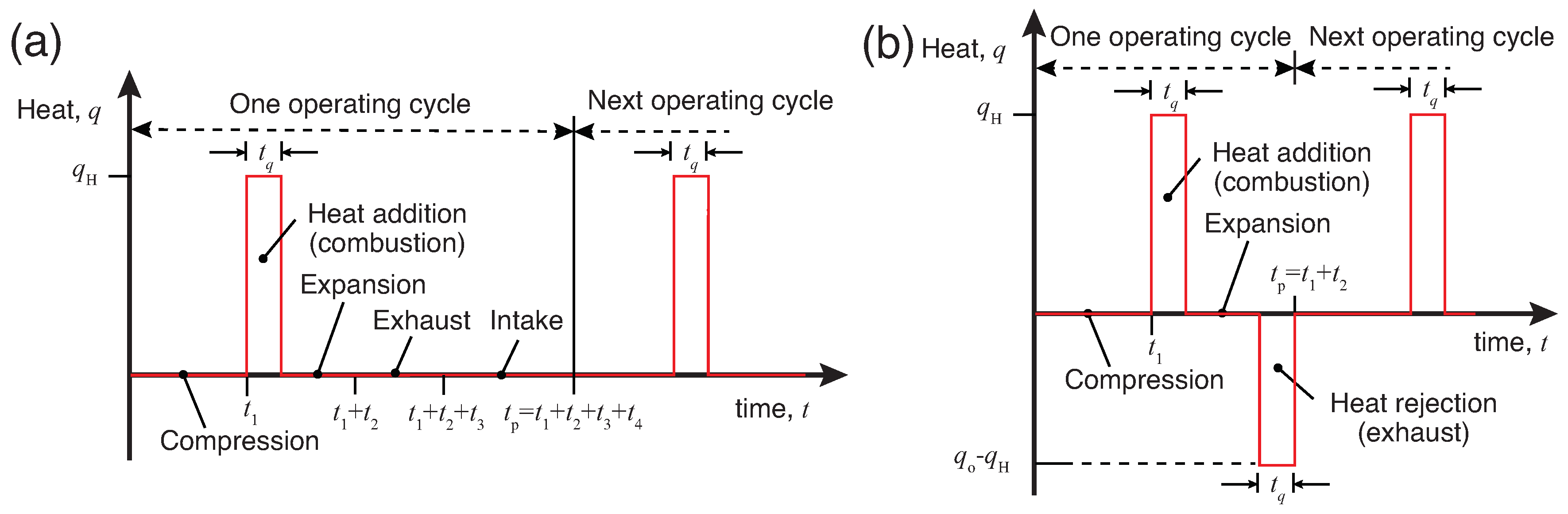
3.1. Pressure-Volume and Force-Displacement Diagrams

The PV diagrams for both the open and closed cycles shown in Figure 4 are generated by applying a heat pulse that corresponds to lean combustion (equivalence ratio ϕ = 0.51 [20]) of octane in the actuator (Figure 3). The peak pressure P 3 in the actuator for the open and closed cycles are off by a factor of 1.3 (Figure 4a). Please note that the temperature rise in both the cycles are equal ( Δ T 23 = 2064 K) because the equivalence ratio for both the cycles are equal ( ϕ = 0.51). Also, please note that the pressure rise Δ P 23 among the cycles is different, as the density of air at the thermodynamic state 2 in both the cycles are unequal—for the closed cycle, the density at state 2 is 1.10 kg/m3, while for the open cycle, the density at state 2 is 1.87 kg/m3. The actuator pressure at the end of heat rejection or blow down process is ambient pressure ( P 5 = 0 kPa gage) and below the ambient pressure ( P 5 = −11 kPa gage) for the open and closed cycles, respectively. This is because the open cycle interacts with the surroundings via mass transfer that allows the actuator pressure to quickly equilibrate to the ambient conditions, while in the closed cycle there is no mechanism, i.e., no mass transfer or heat transfer h = 0 W/K to equilibrate the actuator pressure to the ambient conditions.
In the context of force and displacement generated, the actuator produces a peak force of up to 400 N and displacement stroke of up to 16 cm (Figure 4a). Please note that the force generated is not uniform over the displacement range, but reduces in magnitude with the displacement.
The work done by the reference actuator in both the closed and open cycles for ϕ = 0.51 are found to be 16.96 J and 53.19 J. These correspond to indicated thermal efficiencies of 47.66% and 38.41%, respectively. The CR and ER for the closed cycle are equal to 5.05, while the CR and ER for the open cycle are found to be 1.76 and 4.13, respectively (Table 1). This result indicates that despite the same equivalence ratio ϕ the open and closed cycles respond differently with different performance metrics quantified in terms of stroke lengths, peak pressures, and indicated work.
For the reference actuator, the addition of extra load (an increment by 1.5 N-s/m), results in shorter displacement strokes, and the addition of external work modeled by b p = 40 N-s/m during the intake process 7→1 results in significantly altering the PV diagram for the open cycle (comparing Figure 4a,b). The actuator performance metrics for the open and closed cycles are given in Table 1.

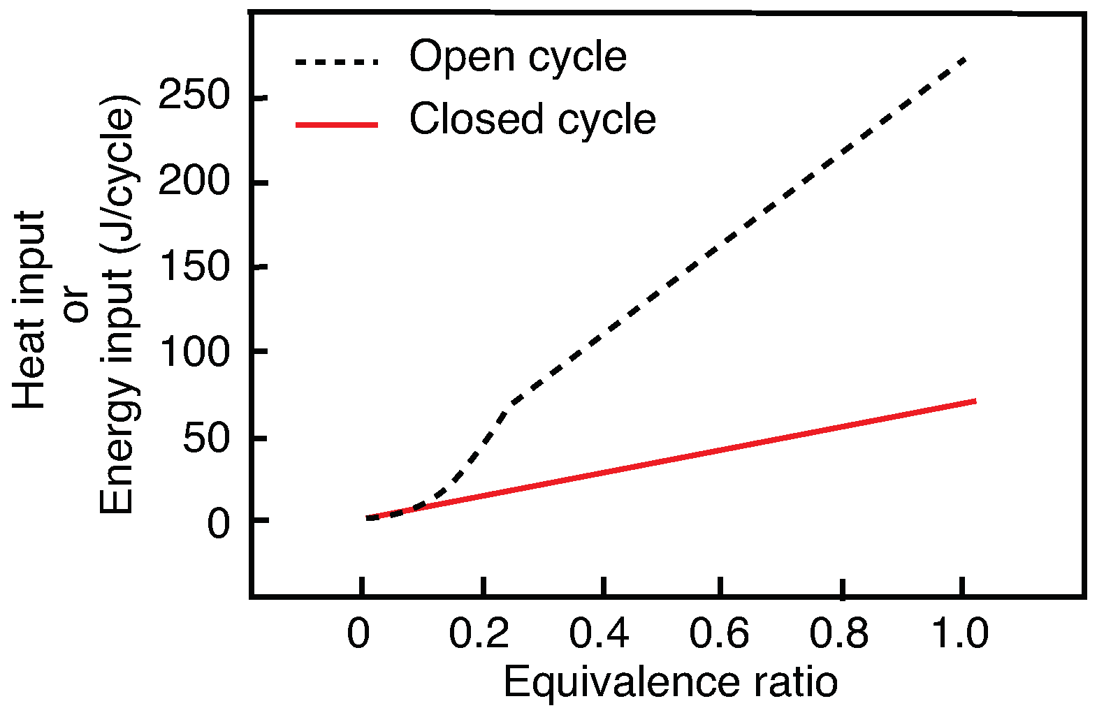
3.2. Equivalence Ratio and Heat Input Relationship

For a specific fuel, an equivalence ratio is dependent on the mass of fuel injected (or associated heat input) and the mass of air inducted into the actuator [19]. Figure 5 graphically shows the relation between heat input and corresponding equivalence ratio ϕ for the reference actuator in open and closed cycles. Each plot in the figure is obtained by supplying the actuator with varying heat, and the corresponding equivalence ratios are calculated based on the mass of air in the cavity CV at state 1. It is clear from the figure that for a fixed equivalence ratio, the amount of heat added per cycle is higher for open cycle operation compared to a closed cycle operation. Furthermore, from the figure, the closed cycle operation holds a linear relationship between the equivalence ratio and heat input, while the open cycle holds a nonlinear linear for low ϕ (< 0.23) and eventually transmutes to linear higher ϕ (> 0.23). A similar observation was reported in [10].

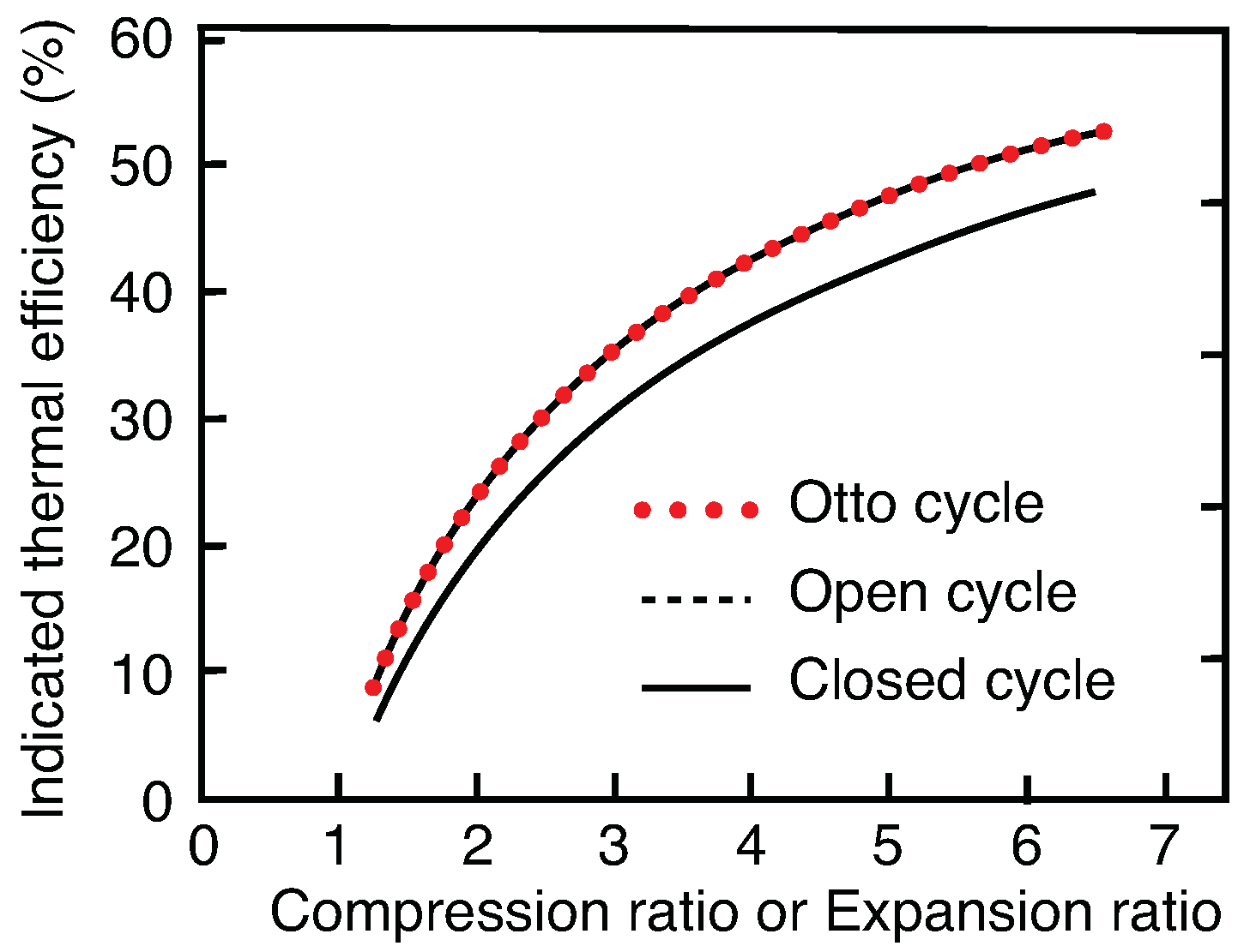
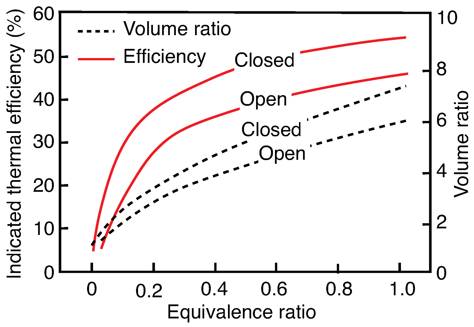
3.3. Efficiency and Volume Ratios

For a fixed equivalence ratio (say ϕ = 0.5), a difference of about 10% in indicated thermal efficiency is observed between the open and closed cycles (Figure 6). The higher efficiencies of the closed cycle operations are because of ignoring the pumping losses in the actuator associated with the exhaust and intake processes. Furthermore, as can be seen in figure, an increase in the heat input or equivalence ratio ϕ increases the volume ratio (ER or CR). This is because a higher heat input or equivalence ratio ϕ will result in the higher pressure at the thermodynamic state 3 (Figure 4), resulting in pushing the piston further outward and causing higher volume ratios. To compare the performance of the actuator against an Otto cycle-based engine, a plot of efficiency against volumetric ratio (CR or ER) is generated for identical physical and operating parameters (Figure 7). The Otto cycle efficiency is computed using the relation η O t t o = 1 1 C R γ 1 [19]. For a closed cycle, the actuator operates like an Otto cycle—same thermodynamic processes and equal compression ratio; hence the efficiencies for the closed and Otto cycle are equal for any given volume ratio. As aforementioned, the pumping losses in the open cycle results in lower thermal efficiencies compared to the closed or Otto cycles.

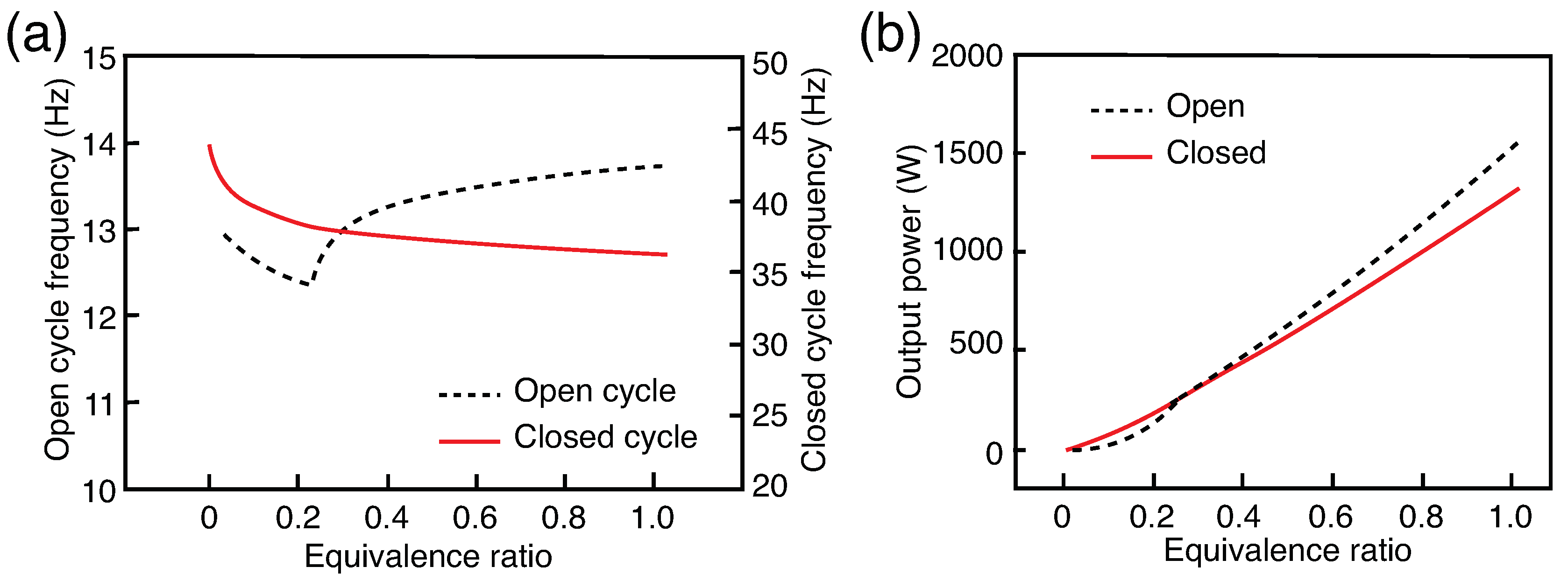
3.4. Operating Frequency and Power Output

It is evident from Figure 8 that the operating frequency and output power from the actuator depends on the equivalence ratio. For the closed cycle, the operating frequency decreases monotonically with increasing equivalence ratio. On the contrary, for the open cycle, the operating frequency first decreases and later increases. This is because the actuator at state 6 (Figure 2) reaches its lower displacement limit with a nonzero piston velocity—resulting in an abrupt changes the direction of actuator motion—reducing the travel distance and time period or increasing the operating frequency of the operating cycle. For the reference actuator, the operating frequency for a closed cycle is 37.03 Hz while for an open cycle is 13.37 Hz. The operating frequency depends predominantly on the number of strokes involved in an operating cycle, higher the number of strokes lower is operating frequency. For instance, a closed cycle has two strokes, while an open cycle has four strokes.
In the context of power output, the actuator produces a peak output power of up to 1500 W for an equivalence ratio of ϕ = 1 (Figure 8b). The power output is a product of energy output and operating frequency of the actuator. Despite the operating frequency moderately increasing or decreasing, the trend in output power is fairly increasing—because the efficiency of the actuator and the energy input or output increases with the equivalence ratio ϕ (Figure 5 and Figure 6).

4. Conclusions

This work describes the difference in the behavior and performance of a combustion-based mesoscale thermal actuator in both open and closed operating cycles. For this, a physics-based lumped parameter model of the actuator is derived using a spring-mass-damper analogy and taking an air standard cycle approach. Three observations are reported: (1) for nominal heat inputs (140 J/cycle), the actuator can produce large displacement strokes (16 cm) that is suitable for driving mesoscale robots; (2) the efficiency of the actuator depends on the heat input; and (3) for a specific heat input, both the open and closed cycle operations respond differently—with different stroke lengths, peak pressures, and thermal efficiencies. Our study reveals that the performance metrics of the actuator make it an ideal candidate for high speed, large force, and large displacement stroke related applications.

Funding

This research received no external funding.

Conflicts of Interest

The author declares no conflict of interest.

Abbreviations

The following abbreviations are used in this manuscript:
ERExpansion Ratio
CRCompression Ratio
CVControl Volume or Cavity
TDCTop Dead Center
BDCBottom Dead Center

References

  1. Bell, D.J.; Lu, T.J.; Fleck, N.A.; Spearing, S.M. MEMS actuators and sensors: Observations on their performance and selection for purpose. J. Micromech. Microeng. 2005, 15, S153–S164. [Google Scholar] [CrossRef]
  2. Henriksson, J.; Gullo, M.; Brugger, J. Integrated long-range thermal bimorph actuators for parallelizable Bio-AFM applications. In Proceedings of the 2012 IEEE SENSORS, Taipei, Taiwan, 28–31 October 2012; pp. 1–4. [Google Scholar] [CrossRef]
  3. Butler, J.T.; Bright, V.M.; Cowan, W.D. Average power control and positioning of polysilicon thermal actuators. Sens. Actuators A Phys. 1999, 72, 88–97. [Google Scholar] [CrossRef]
  4. Lu, T.; Hutchinson, J.; Evans, A. Optimal design of a flexural actuator. J. Mech. Phys. Solids 2001, 49, 2071–2093. [Google Scholar] [CrossRef]
  5. Bardaweel, H.; Preetham, B.S.; Richards, R.; Richards, C.; Anderson, M. MEMS-based resonant heat engine: Scaling analysis. Microsyst. Technol. 2011, 17, 1251–1261. [Google Scholar] [CrossRef]
  6. Nakajima, N.; Ogawa, K.; Fujimasa, I. Study on micro engines-miniaturizing Stirling engines for actuators and heatpumps. In Proceedings of the IEEE Micro Electro Mechanical Systems, ‘An Investigation of Micro Structures, Sensors, Actuators, Machines and Robots’, Salt Lake City, UT, USA, 20–22 February 1989; pp. 145–148. [Google Scholar] [CrossRef]
  7. Preetham, B.S.; Anderson, M.; Richards, C. Modeling of a resonant heat engine. J. Appl. Phys. 2012, 112, 124903. [Google Scholar] [CrossRef]
  8. Formosa, F.; Fréchette, L.G. Scaling laws for free piston Stirling engine design: Benefits and challenges of miniaturization. Energy 2013, 57, 796–808. [Google Scholar] [CrossRef]
  9. Preetham, B.S.; Anderson, M.; Richards, C. Estimation of parasitic losses in a proposed mesoscale resonant engine: Experiment and model. J. Appl. Phys. 2014, 115, 054904. [Google Scholar] [CrossRef]
  10. Preetham, B.S.; Anderson, M.; Richards, C. Mathematical modeling of a four-stroke resonant engine for micro and mesoscale applications. J. Appl. Phys. 2014, 116, 214904. [Google Scholar] [CrossRef]
  11. Burugupally, S.; Weiss, L. Power generation via small length scale thermo-mechanical systems: Current status and challenges, a review. Energies 2018, 11, 2253. [Google Scholar] [CrossRef]
  12. Burugupally, S.P. Development of a Small Scale Resonant Engine for Micro and Mesoscale Applications. Ph.D. Thesis, Washington State University, Washington, DC, USA, 2014. [Google Scholar]
  13. Burugupally, S.P.; Weiss, L. Design and performance of a miniature free piston expander. Energy 2019, 170, 611–618. [Google Scholar] [CrossRef]
  14. Burugupally, S.P.; Weiss, L.; Depcik, C. The effect of working fluid properties on the performance of a miniature free piston expander for waste heat harvesting. Appl. Therm. Eng. 2019, 151, 431–438. [Google Scholar] [CrossRef]
  15. Preetham, B.; Weiss, L. Investigations of a new free piston expander engine cycle. Energy 2016, 106, 535–545. [Google Scholar] [CrossRef]
  16. Ouyang, X.; Ding, S.; Fan, B.; Li, P.Y.; Yang, H. Development of a novel compact hydraulic power unit for the exoskeleton robot. Mechatronics 2016, 38, 68–75. [Google Scholar] [CrossRef]
  17. Raibert, M.; Blankespoor, K.; Nelson, G.; Playter, R. Bigdog, the rough-terrain quadruped robot. IFAC Proc. Vol. 2008, 41, 10822–10825. [Google Scholar] [CrossRef]
  18. Bradley, D.; Acosta-Marquez, C.; Hawley, M.; Brownsell, S.; Enderby, P.; Mawson, S. NeXOS – The design, development and evaluation of a rehabilitation system for the lower limbs. Mechatronics 2009, 19, 247–257. [Google Scholar] [CrossRef]
  19. Pulkrabek, W. Engineering Fundamentals of the Internal Combustion Engine; Prentice Hall: Englewood Cliffs, NJ, USA, 1997. [Google Scholar]
  20. Heywood, J. Internal Combustion Engine Fundamentals; McGraw-Hill Education: New York, NY, USA, 1988. [Google Scholar]
Figure 1. Proposed thermal actuator (a) schematic sketch and (b) lumped model. CV denotes the cavity or control volume with state parameters: pressure P, volume V, and temperature T at time t. The valve on the left is used for the intake or exhaust of the working fluid (air). The valve is connected to the ambient atmosphere ( P o , T o ) during the intake and exhaust processes. For the closed cycle, the valve remains closed over the entire operating cycle.
Actuators 08 00073 g001
Figure 2. Ideal pressure-volume diagram of the actuator in open and closed cycle operations. Processes 1→2: Compression; 2→3: Heat addition for duration t q ; and 3→4: Expansion. For closed cycle, process 4→1 is heat rejection for duration t q . For open cycle, processes 4→5: Blowdown phase of exhaust; 5→6: Displacement phase of exhaust; 6→7→1: Intake. Note the piston positions at states 6 and 7 are ‘Top Dead Center’ (TDC) and states 4 and 5 are ‘Bottom Dead Center’ (BDC), respectively.
Actuators 08 00073 g002
Figure 3. Heat-rate function q for modeling the (a) open and (b) closed cycle operations.
Actuators 08 00073 g003
Figure 4. Open and closed cycle pressure-volume and force-displacement diagrams for (a) the reference actuator (b) an actuator with b = 27.5 N-s/m, b p = −40 N-s/m and ϕ = 0.51.
Actuators 08 00073 g004
Figure 5. Relationship between the heat input and equivalence ratio for the reference actuator for open and closed cycle operations.
Actuators 08 00073 g005
Figure 6. Efficiency and volume ratios for the reference actuator for open and closed cycles.
Actuators 08 00073 g006
Figure 7. Comparison of the indicated thermal efficiencies of the reference actuator in open, closed, and Otto cycles.
Actuators 08 00073 g007
Figure 8. Performance metrics of the reference actuator in open and closed operating cycles: (a) Operating frequency and (b) Power output.
Actuators 08 00073 g008
Table 1. Comparison of the performance metrics for the reference actuator in closed and open cycles with equivalence ratio ϕ = 0.51.
Performance ParameterClosed CycleOpen Cycle
Indicated thermal efficiency (%)47.6638.41
Brake thermal efficiency (%)44.3334.64
Heat added per cycle (J/cycle)35.6138.5
Cycle frequency (Hz)37.0313.37
Compression ratio, CR5.051.76
Expansion ratio, ER5.054.13
Average piston speed (m/s)4.754.77
Power output (W)584.7641.6
Mass of air in cylinder (kg/cycle)2.41 × 10 5 9.28 × 10 5

