Mechanical Simplification of Variable-Stiffness Actuators Using Dielectric Elastomer Transducers

 , , , and
Abstract
1. Introduction
2. Design
3. Modeling of Variable-Stiffness Module
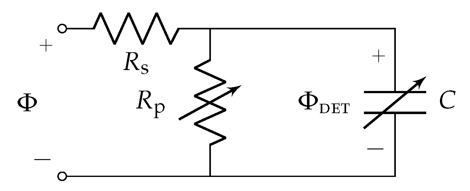
3.1. Electrical
3.2. Mechanical
3.3. Effect of Module Dimensions
4. Results and Discussion
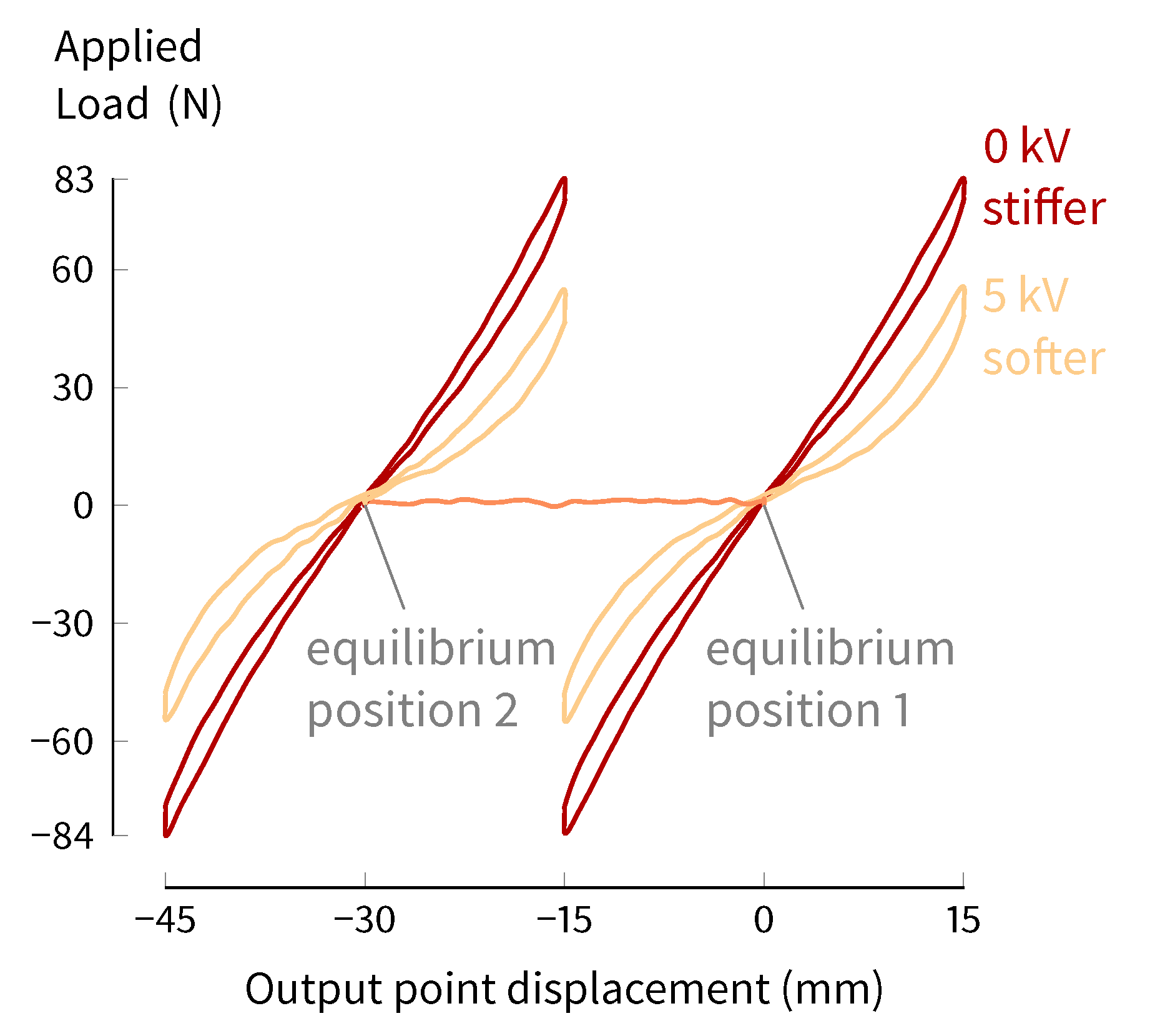
4.1. Modulation of Stiffness and Equilibrium Position
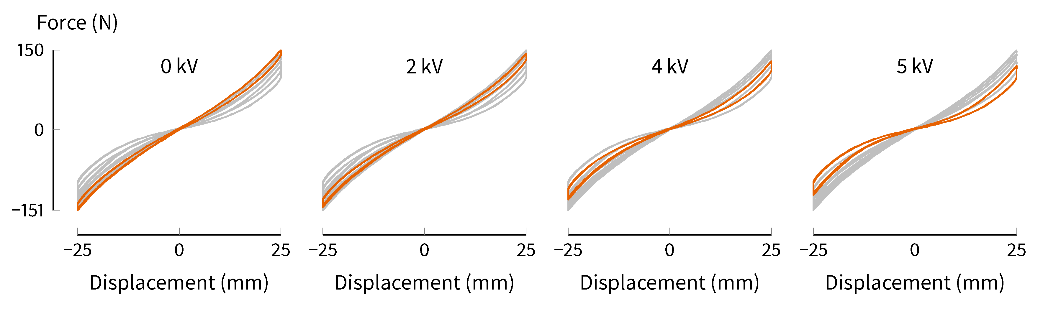
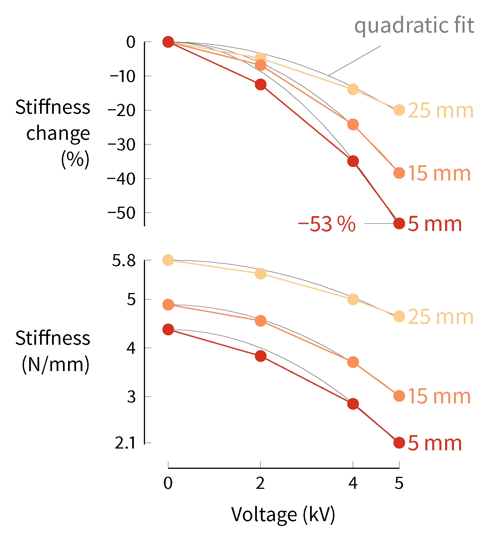
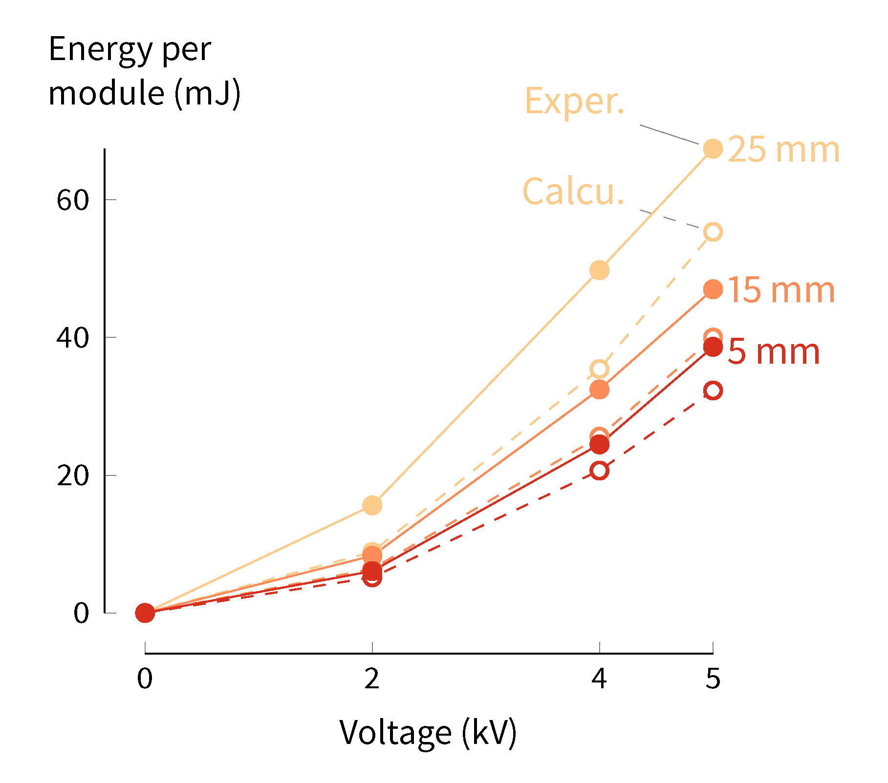
4.2. Stiffness Change Magnitude
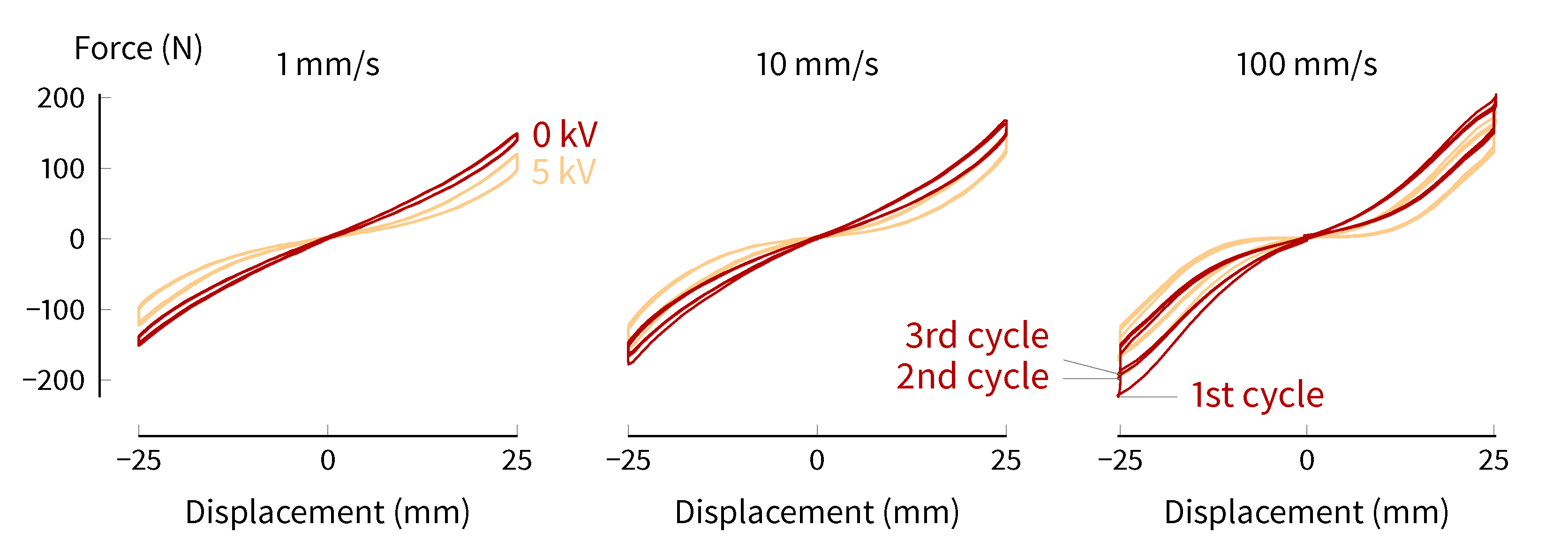
4.3. Stiffness Change Speed
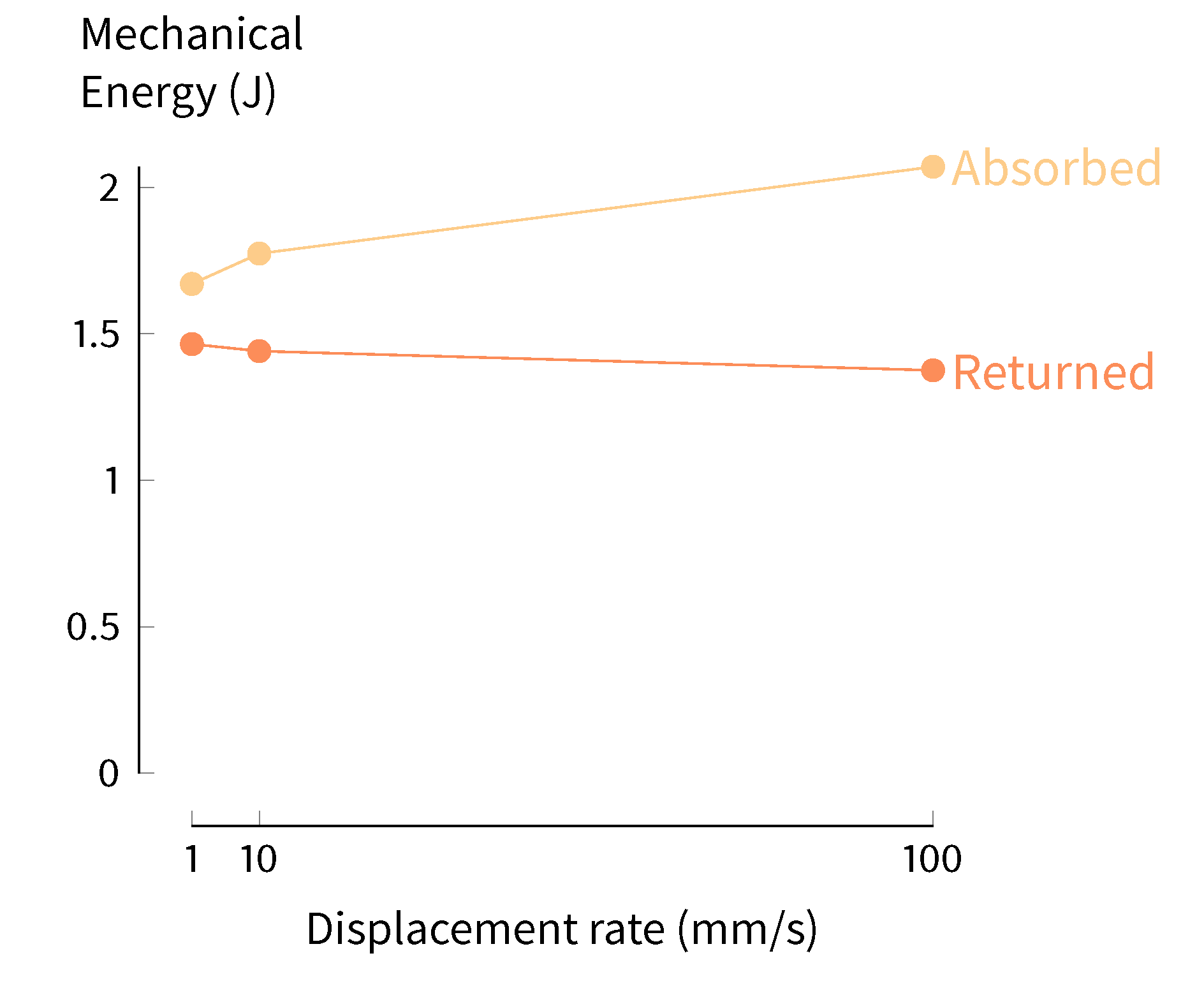
4.4. Viscoelasticity
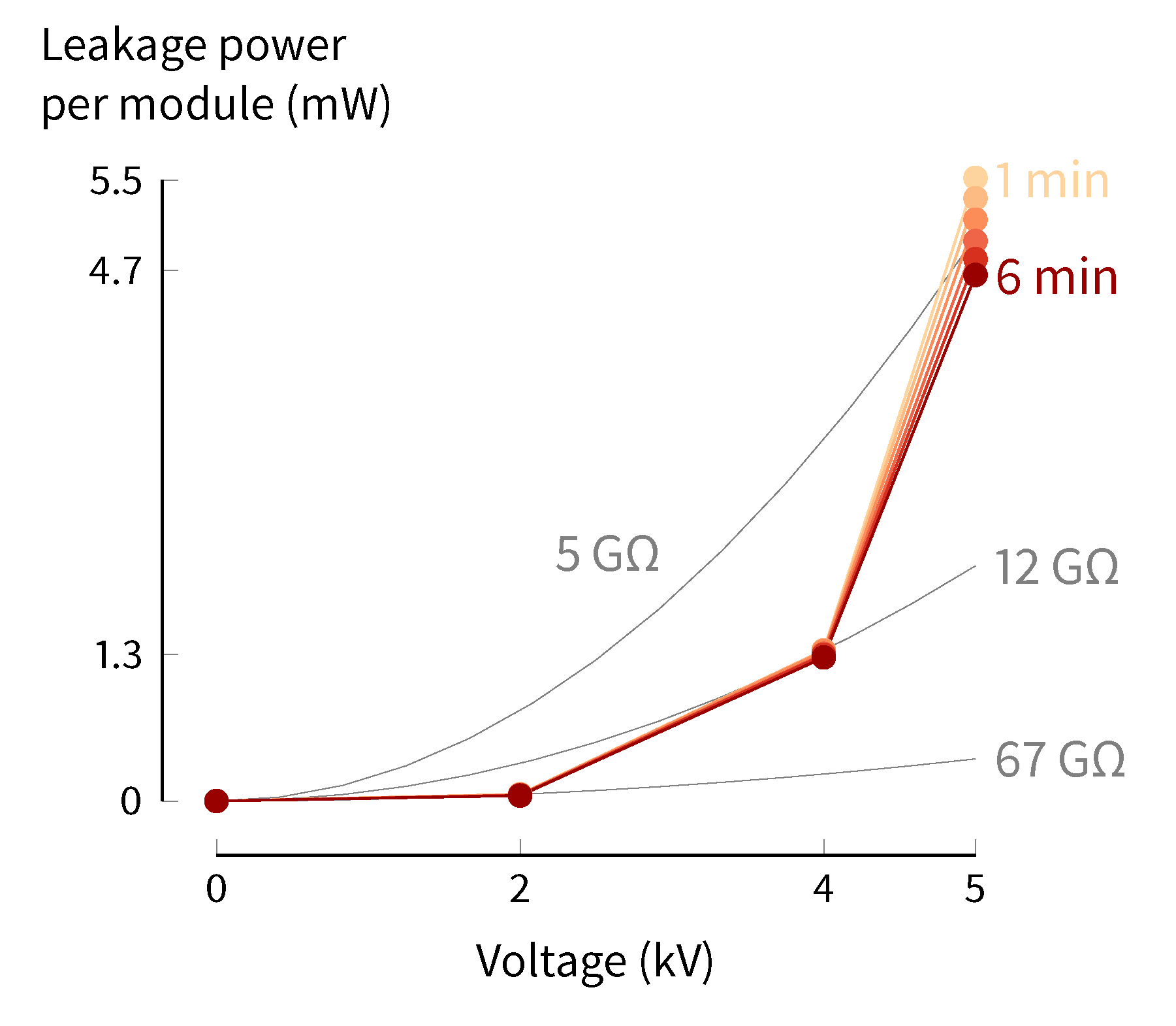
4.5. Electrical Power Requirements for Stiffness Change
4.6. Maximum Displacement of Variable-Stiffness Mechanism
4.7. Discussion of Solutions for DET Weaknesses
5. Conclusions
Author Contributions
Funding
Acknowledgments
Conflicts of Interest
Abbreviations
| DET | Dielectric elastomer transducer |
| VHB | Very high bond. A line of adhesive tapes produced by 3M |
| UTM | Universal testing machine |
| VSA | Variable-stiffness actuator |
Appendix A. Materials and Methods
Appendix A.1. DET Materials
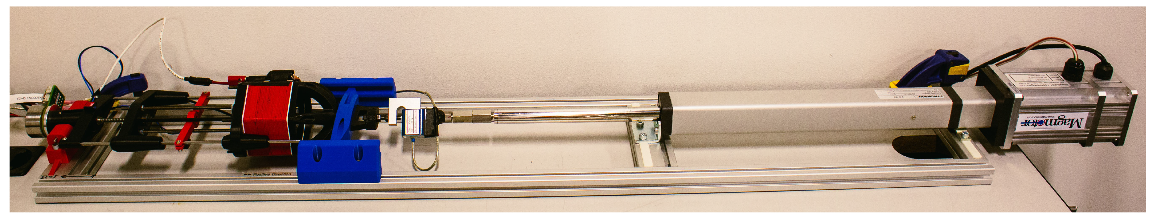
Appendix A.2. Testbed

Appendix A.3. Test Procedures
References
- Rezazadeh, S.; Abate, A.; Hatton, R.L.; Hurst, J.W. Robot Leg Design: A Constructive Framework. IEEE Access 2018, 6, 54369–54387. [Google Scholar] [CrossRef]
- Hurst, J.W.; Rizzi, A.A. Series Compliance for an Efficient Running Gait. IEEE Robot. Autom. Mag. 2008, 15, 42–51. [Google Scholar] [CrossRef]
- Rouse, E.J.; Mooney, L.M.; Herr, H.M. Clutchable series-elastic actuator: Implications for prosthetic knee design. Int. J. Robot. Res. 2014, 33, 1611–1625. [Google Scholar] [CrossRef]
- Galloway, K.C.; Clark, J.E.; Koditschek, D.E. Variable Stiffness Legs for Robust, Efficient, and Stable Dynamic Running. J. Mech. Robot. 2013, 5, 011009. [Google Scholar] [CrossRef]
- Grimmer, M.; Seyfarth, A. Stiffness Adjustment of a Series Elastic Actuator in an Ankle-Toot Prosthesis for Walking and Running: The Trade-Off Between Energy and Peak Power Optimization. In Proceedings of the IEEE International Conference on Robotics and Automation, Shanghai, China, 9–13 May 2011; pp. 1439–1444. [Google Scholar] [CrossRef]
- Cestari, M.; Sanz-Merodio, D.; Garcia, E. A New and Versatile Adjustable Rigidity Actuator with Add-on Locking Mechanism (ARES-XL). Actuators 2018, 7. [Google Scholar] [CrossRef]
- Grosu, V.; Rodriguez-Guerrero, C.; Grosu, S.; Vanderborght, B.; Lefeber, D. Design of Smart Modular Variable Stiffness Actuators for Robotic-Assistive Devices. IEEE/ASME Trans. Mechatron. 2017, 22, 1777–1785. [Google Scholar] [CrossRef]
- Vanderborght, B.; Albu-Schaeffer, A.; Bicchi, A.; Burdet, E.; Caldwell, D.G.; Carloni, R.; Catalano, M.; Eiberger, O.; Friedl, W.; Ganesh, G.; et al. Variable Impedance Actuators: A Review. Robot. Auton. Syst. 2013, 61, 1601–1614. [Google Scholar] [CrossRef]
- Jafari, A.; Vu, H.Q.; Iida, F. Determinants for Stiffness Adjustment Mechanisms. J. Intell. Robot. Syst. 2016, 82, 435–454. [Google Scholar] [CrossRef]
- Braun, D.J.; Chalvet, V.; Dahiya, A. Positive–Negative Stiffness Actuators. IEEE Trans. Robot. 2018, 35, 162–173. [Google Scholar] [CrossRef]
- Diller, S.; Majidi, C.; Collins, S.H. A Lightweight, Low-Power Electroadhesive Clutch and Spring for Exoskeleton Actuation. In Proceedings of the IEEE International Conference on Robotics and Automation, Stockholm, Sweden, 16–21 May 2016; pp. 682–689. [Google Scholar] [CrossRef]
- Dastoor, S.; Cutkosky, M.R. Design of Dielectric Electroactive Polymers for a Compact and Scalable Variable Stiffness Device. In Proceedings of the IEEE International Conference on Robotics and Automation, Saint Paul, MN, USA, 14–18 May 2012; pp. 3745–3750. [Google Scholar] [CrossRef]
- Newton, J.; Morton, J.; Clark, J.; Oates, W.S. Modeling and Characterization of Stiffness Controlled Robotic Legs Using Dielectric Elastomers. In Proceedings of the SPIE Smart Structures and Materials + Nondestructive Evaluation and Health Monitoring, San Diego, CA, USA, 11–15 March 2012; Volume 8340, p. 83400Z. [Google Scholar] [CrossRef]
- Orita, A.; Cutkosky, M.R. Scalable Electroactive Polymer for Variable Stiffness Suspensions. IEEE/ASME Trans. Mechatron. 2016, 21, 2836–2846. [Google Scholar] [CrossRef]
- Hodgins, M.; York, A.; Seelecke, S. Experimental Comparison of Bias Elements for Out-Of-Plane DEAP Actuator System. Smart Mater. Struct. 2013, 22, 094016. [Google Scholar] [CrossRef]
- Hau, S.; Rizzello, G.; Hodgins, M.; York, A.; Seelecke, S. Design and Control of a High-Speed Positioning System Based on Dielectric Elastomer Membrane Actuators. IEEE/ASME Trans. Mechatron. 2017, 22, 1259–1267. [Google Scholar] [CrossRef]
- Berselli, G.; Vertechy, R.; Babič, M.; Parenti Castelli, V. Implementation of a Variable Stiffness Actuator Based on Dielectric Elastomers: A Feasibility Study. In ASME Conference on Smart Materials, Adaptive Structures and Intelligent Systems; ASME: Stone Mountain, GA, USA, 2012; pp. 497–506. [Google Scholar]
- Carpi, F.; Frediani, G.; Gerboni, C.; Gemignani, J.; De Rossi, D. Enabling Variable-Stiffness Hand Rehabilitation Orthoses with Dielectric Elastomer Transducers. Med. Eng. Phys. 2014, 36, 205–211. [Google Scholar] [CrossRef]
- Bolívar, E.; Allen, D.P.; Ellson, G.; Cossio, J.; Voit, W.; Gregg, R.D. Towards a Series Elastic Actuator with Electrically Modulated Stiffness for Powered Ankle-Foot Orthoses. In Proceedings of the IEEE International Conference on Automation Science and Engineering, Fort Worth, TX, USA, 21–25 August 2016; pp. 1086–1093. [Google Scholar] [CrossRef]
- Pelrine, R.; Kornbluh, R.D. Dielectric Elastomers as Electroactive Polymers (EAPs): Fundamentals. In Electromechanically Active Polymers. Polymers and Polymeric Composites: A Reference Series; Carpi, F., Ed.; Springer: Cham, Switzerland, 2016; Chapter 30; pp. 671–686. [Google Scholar] [CrossRef]
- Pelrine, R.; Kornbluh, R.D. Electromechanical Transduction Effects in Dielectric Elastomers: Actuation, Sensing, Stiffness Modulation and Electric Energy Generation. In Dielectric Elastomers as Electromechanical Transducers; Carpi, F., De Rossi, D., Kornbluh, R.D., Pelrine, R., Sommer-Larsen, P., Eds.; Elsevier Science: Amsterdam, The Netherlands, 2008; Chapter 1; pp. 3–12. [Google Scholar] [CrossRef]
- Pelrine, R. Variable Stiffness Mode: Devices and Applications. In Dielectric Elastomers as Electromechanical Transducers; Carpi, F., De Rossi, D., Kornbluh, R., Pelrine, R., Sommer-Larsen, P., Eds.; Springer: Cham, Switzerland, 2008; Chapter 14; pp. 141–145. [Google Scholar] [CrossRef]
- Choi, H.R.; Jung, K.; Ryew, S.; Nam, J.D.; Jeon, J.; Koo, J.C.; Tanie, K. Biomimetic Soft Actuator: Design, Modeling, Control, and Applications. IEEE/ASME Trans. Mechatron. 2005, 10, 581–593. [Google Scholar] [CrossRef]
- Visser, L.C.; Carloni, R.; Stramigioli, S. Energy-Efficient Variable Stiffness Actuators. IEEE Trans. Robot. 2011, 27, 865–875. [Google Scholar] [CrossRef]
- Jafari, A.; Tsagarakis, N.; Caldwell, D. Energy Efficient Actuators with Adjustable Stiffness: A Review on AwAS, AwAS-II and CompACT VSA Changing Stiffness Based on Lever Mechanism. Ind. Robot Int. J. 2015, 42, 242–251. [Google Scholar] [CrossRef]
- Rizzello, G. Modeling, Control and Self-Sensing of Dielectric Elastomer Actuators. Ph.D. Thesis, Polytechnic University of Bari, Bari, Italy, 2016. [Google Scholar]
- Rizzello, G.; Hodgins, M.; Naso, D.; York, A.; Seelecke, S. Modeling of the Effects of the Electrical Dynamics on the Electromechanical Response of a DEAP Circular Actuator with a Mass–Spring Load. Smart Mater. Struct. 2015, 24, 094003. [Google Scholar] [CrossRef]
- Hau, S.; York, A.; Rizzello, G.; Seelecke, S. Performance Prediction and Scaling laws of Circular Dielectric Elastomer Membrane Actuators. J. Mech. Des. 2018, 140, 113501. [Google Scholar] [CrossRef]
- Wang, D. The Most Energy Efficient Way to Charge the Capacitor in a RC Circuit. Phys. Educ. 2017, 52, 065019. [Google Scholar] [CrossRef]
- He, T.; Zhao, X.; Suo, Z. Dielectric Elastomer Membranes Undergoing Inhomogeneous Deformation. J. Appl. Phys. 2009, 106, 083522. [Google Scholar] [CrossRef]
- Huang, J.; Shian, S.; Diebold, R.M.; Suo, Z.; Clarke, D.R. The Thickness and Stretch Dependence of the Electrical Breakdown Strength of an Acrylic Dielectric Elastomer. Appl. Phys. Lett. 2012, 101, 122905. [Google Scholar] [CrossRef]
- Kofod, G.; Sommer-Larsen, P.; Kornbluh, R.D.; Pelrine, R. Actuation Response of Polyacrylate Dielectric Elastomers. J. Intell. Mater. Syst. Struct. 2003, 14, 787–793. [Google Scholar] [CrossRef]
- Knauss, W.G.; Emri, I.; Lu, H. Mechanics of Polymers: Viscoelasticity. In Springer Handbook of Experimental Solid Mechanics; Sharpe, W., Ed.; Springer: Boston, MA, USA, 2008; Chapter 3; pp. 49–95. [Google Scholar] [CrossRef]
- Di Lillo, L.; Schmidt, A.; Carnelli, D.A.; Ermanni, P.; Kovacs, G.; Mazza, E.; Bergamini, A. Measurement of Insulating and Dielectric Properties of Acrylic Elastomer Membranes at High Electric Fields. J. Appl. Phys. 2012, 111, 024904. [Google Scholar] [CrossRef]
- Capacitance Leakage Current Measurement Techniques Using the B2985A/87A; Application Note; Keysight Technologies: Santa Rosa, CA, USA, 2018.
- Kollosche, M.; Zhu, J.; Suo, Z.; Kofod, G. Complex Interplay of Nonlinear Processes in Dielectric Elastomers. Phys. Rev. E 2012, 85, 051801. [Google Scholar] [CrossRef]
- Patra, K.; Sahu, R.K. A Visco-Hyperelastic Approach to Modelling Rate-Dependent Large Deformation of a Dielectric Acrylic Elastomer. Int. J. Mech. Mater. Des. 2015, 11, 79–90. [Google Scholar] [CrossRef]
- Kornbluh, R.D.; Wong-Foy, A.; Pelrine, R.; Prahlad, H.; McCoy, B. Long-lifetime All-polymer Artificial Muscle Transducers. MRS Proc. 2010, 1271, 1271–JJ03–01. [Google Scholar] [CrossRef]
- Laffranchi, M.; Tsagarakis, N.G.; Caldwell, D.G. Analysis and Development of a Semiactive Damper for Compliant Actuation Systems. IEEE/ASME Trans. Mechatron. 2013, 18, 744–753. [Google Scholar] [CrossRef]
- Kornbluh, R.D.; Pelrine, R. High-Performance Acrylic and Silicone Elastomers. In Dielectric Elastomers as Electromechanical Transducers; Carpi, F., De Rossi, D., Kornbluh, R., Pelrine, R., Sommer-Larsen, P., Eds.; Elsevier Science: Amsterdam, The Netherlands, 2008; Chapter 4; pp. 33–42. [Google Scholar] [CrossRef]
- Madsen, F.B.; Daugaard, A.E.; Hvilsted, S.; Skov, A.L. The Current State of Silicone-Based Dieletric Elastomer Transducers. Macromol. Rapid Commun. 2016, 37, 378–413. [Google Scholar] [CrossRef]
- Romasanta, L.J.; Lopez-Manchado, M.A.; Verdejo, R. Increasing the performance of dielectric elastomer actuators: A review from the materials perspective. Prog. Polym. Sci. 2015, 51, 188–211. [Google Scholar] [CrossRef]
- Shea, H.; Koh, S.J.A.; Graz, I.; Shintake, J. Dielectric Elastomers as EAPs: How to Start Experimenting with Them. In Electromechanically Active Polymers. Polymers and Polymeric Composites: A Reference Series; Carpi, F., Ed.; Springer: Cham, Switzerland, 2016; Chapter 34; pp. 767–787. [Google Scholar] [CrossRef]
- Babič, M.; Vertechy, R.; Berselli, G.; Lenarčič, J.; Parenti Castelli, V.; Vassura, G. An Electronic Driver for Improving the Open and Closed Loop Electro-Mechanical Response of Dielectric Elastomer Actuators. Mechatronics 2010, 20, 201–212. [Google Scholar] [CrossRef]
- Poulin, A.; Rosset, S.; Shea, H.R. Printing Low-Voltage Dielectric Elastomer Actuators. Appl. Phys. Lett. 2015, 107, 244104. [Google Scholar] [CrossRef]
- Vincent, J. Basic Elasticity and Viscoelasticity. In Structural Biomaterials, 3rd ed.; Princeton University Press: Princeton, NJ, USA, 2012; Chapter 1; pp. 1–28. [Google Scholar]


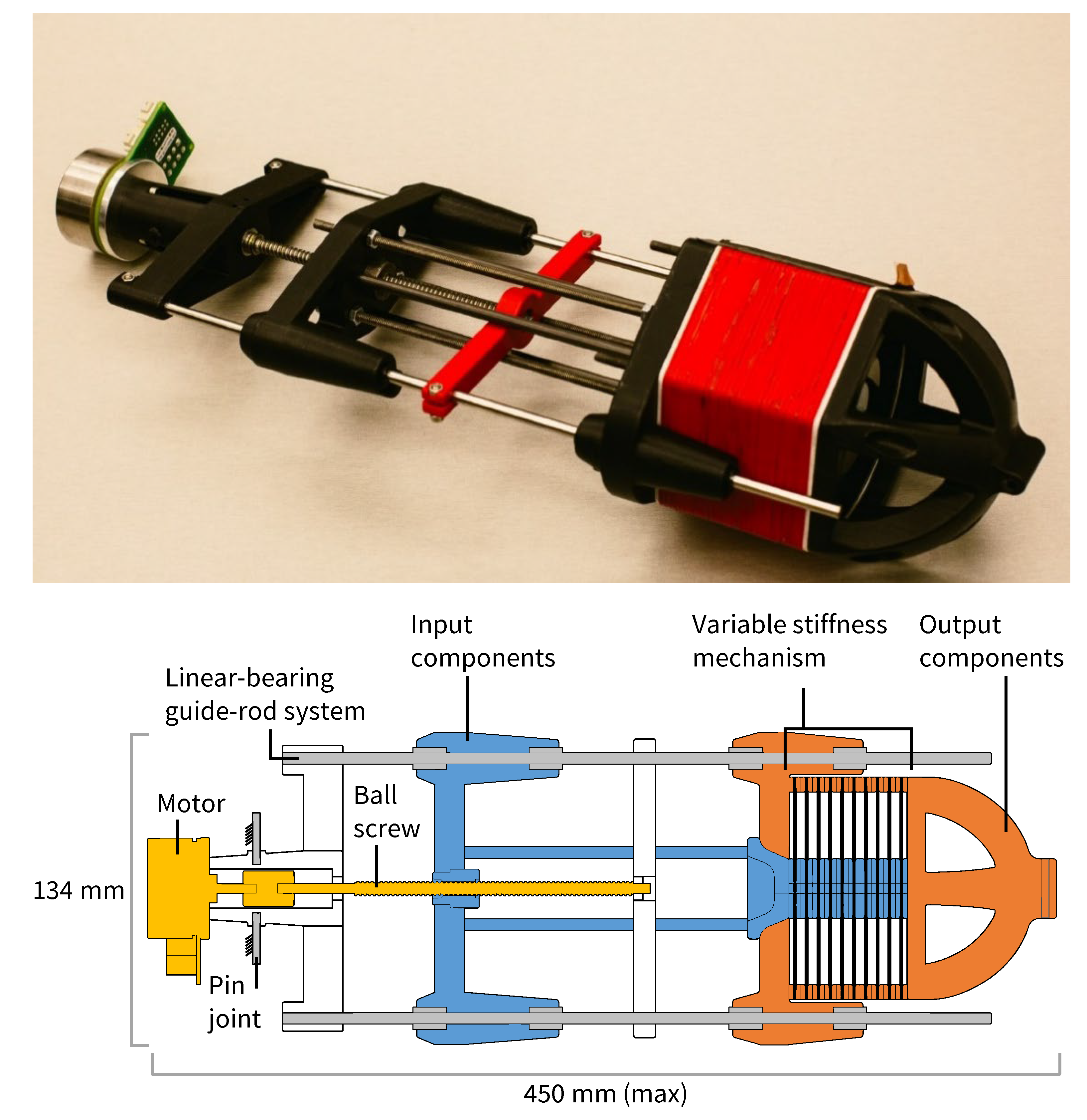
| VSA | |
| Max. length | 450 |
| Output position travel | 90 |
| Equilibrium position travel | 42 |
| Width | 134 |
| Height | 108 |
| Mass | 880 |
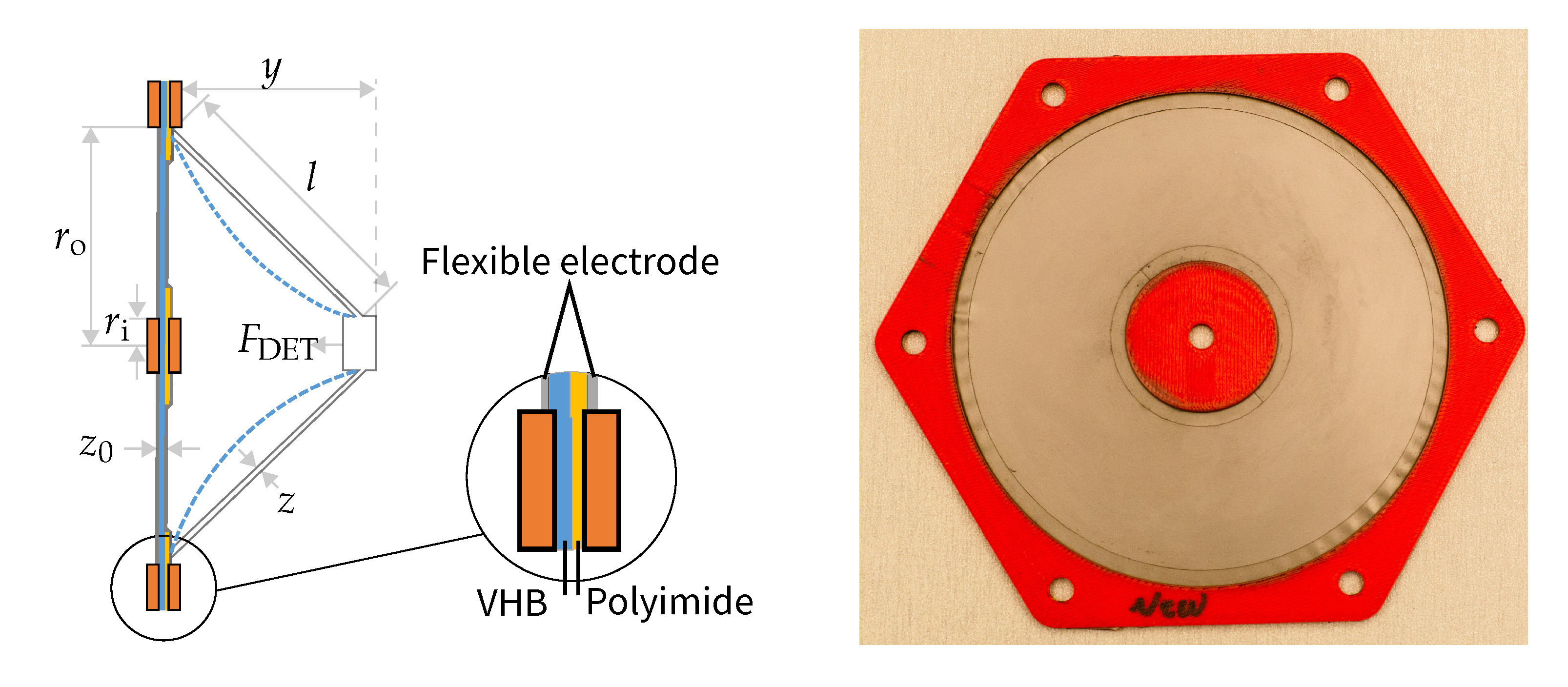
| DET Module | |
| mm | |
| mm | |
| See Section 4.6 | |
| 63 |
| Constant | Increasing | Uncharged Stiffness | Voltage-Induced Stiffness Change | Maximum Displacement | |
|---|---|---|---|---|---|
| Case 1 | increases | increases | is constant | ||
| Case 2 | undetermined | decreases | increases | ||
| Case 3 | undetermined | increases | decreases |
© 2019 by the authors. Licensee MDPI, Basel, Switzerland. This article is an open access article distributed under the terms and conditions of the Creative Commons Attribution (CC BY) license (http://creativecommons.org/licenses/by/4.0/).
Share and Cite
Allen, D.P.; Bolívar, E.; Farmer, S.; Voit, W.; Gregg, R.D. Mechanical Simplification of Variable-Stiffness Actuators Using Dielectric Elastomer Transducers. Actuators 2019, 8, 44. https://doi.org/10.3390/act8020044
Allen DP, Bolívar E, Farmer S, Voit W, Gregg RD. Mechanical Simplification of Variable-Stiffness Actuators Using Dielectric Elastomer Transducers. Actuators. 2019; 8(2):44. https://doi.org/10.3390/act8020044
Chicago/Turabian StyleAllen, David P., Edgar Bolívar, Sophie Farmer, Walter Voit, and Robert D. Gregg. 2019. "Mechanical Simplification of Variable-Stiffness Actuators Using Dielectric Elastomer Transducers" Actuators 8, no. 2: 44. https://doi.org/10.3390/act8020044
APA StyleAllen, D. P., Bolívar, E., Farmer, S., Voit, W., & Gregg, R. D. (2019). Mechanical Simplification of Variable-Stiffness Actuators Using Dielectric Elastomer Transducers. Actuators, 8(2), 44. https://doi.org/10.3390/act8020044