Abstract
One of the key issues in control design for Active Magnetic Bearing (AMB) systems is the tradeoff between the simplicity of the controller structure and the performance of the closed-loop system. To achieve this tradeoff, this paper proposes the design of a fractional order Proportional-Integral-Derivative (FOPID) controller. The FOPID controller consists of only two additional parameters in comparison with a conventional PID controller. The feasibility of FOPID for AMB systems is investigated for rotor suspension in both the radial and axial directions. Tuning methods are developed based on the evolutionary algorithms for searching the optimal values of the controller parameters. The resulting FOPID controllers are then tested and compared with a conventional PID controller, as well as with some advanced controllers such as Linear Quadratic Gausian (LQG) and controllers. The comparison is made in terms of various stability and robustness specifications, as well as the dimensions of the controllers as implemented. Lastly, to validate the proposed method, experimental testing is carried out on a single-stage centrifugal compressor test rig equipped with magnetic bearings. The results show that, with a proper selection of gains and fractional orders, the performance of the resulting FOPID is similar to those of the advanced controllers.
1. Introduction
The use of magnetic forces to overcome the forces exerted on a moving mechanical body is the fundamental idea behind how magnetic bearings work. There are several benefits of magnetic bearings over conventional bearings, such as low losses due to non-contact operation and active control capability which can enhance the stability of the system. Furthermore, as a result of low mechanical wear and losses, system maintenance costs are significantly lower. Commercial applications that employ magnetic bearings include compressors, centrifuges, high-speed turbines, energy-storage flywheels, and high-precision machine tools. Magnetic bearings can be either passive or active. Passive Magnetic Bearings use repulsive forces from the interaction of similar poles of two permanent magnets to keep the rotor away from the bearing surfaces. Active Magnetic Bearings (AMB) use actively controlled electromagnetic forces to control the motion of a rotor or another ferromagnetic body in the air. An AMB system normally consists of sensors, electromagnets, power amplifiers, power supplies, and controllers [1]. Figure 1 shows the basic principle of an AMB system in one degree of freedom.
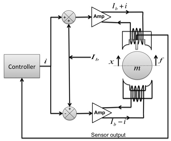
Figure 1.
AMB system in one degree of freedom.
The position sensor detects how far away the rotor is from the magnet. This information is sent to the controller, which outputs proper voltages to the power amplifiers, which in turn apply currents to the electromagnets. The electromagnets then generate magnetic forces to balance the rotor to the desired position (i.e., the center of the clearance space). Magnetic bearings for the radial directions are called Radial Bearings and those in the axial direction are called Thrust Bearings. A complete assembly of AMB components is illustrated in Figure 2.
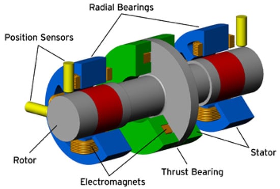
Figure 2.
Assembly of an AMB system.
An AMB system is inherently open loop unstable. Therefore it is required to have a controller in the feedback loop to stabilize the system during the operation. Normally, the controller design for an AMB system starts with a Proportional-Integral-Derivative (PID) controller because of its simple structure. Recall here for easy reference that the transfer function of a PID controller is given as
The controller parameters can be tuned intuitively, where the proportional gain has a similar effect as adding stiffness, and the derivative gain acts as the added damping to the system. In addition, the integral gain helps in reducing the rotor position offset due to a static disturbance. Note that the form of a PID controller in Equation (1) is not a proper form for implementation. An additional term such as a lowpass filter is required. There are two popular methods in applying a PID controller to an AMB system. The first method is called the decentralized PID where an actuator pair of each control axis works independently from other pairs. The advantage of using the decentralized PID is the simplicity in tuning the controller parameters for one control axis at a time. However, the lateral dynamics of the rotor at different bearing locations are coupled. Thus, there may be some limitation in achieving the desired performance by using a decentralized method. The second method is called the centralized or tilt-and-translate method. This method decouples the two rigid body modes, the tilt mode and the translate mode, and uses two separate PID controllers to stabilize each mode independently. More detail on the tilt-and-translate method can be found in [2]. Nevertheless, these two types of PID controllers have limitations when dealing with non-collocation of sensors and the flexible modes of the rotor. As such, additional filters are required in order to stabilize the closed-loop system.
Given the above-mentioned shortcomings of the PID controllers, some advanced controllers have been developed to stabilize an AMB system for better performance. These controllers are multiple-input multiple-output (MIMO) and centralized. Examples of advanced controllers used in AMB systems are Linear Quadratic Regulator (LQR), , and μ-synthesis controllers. The objective of the LQR controller design is to find the optimal state feedback gain K that minimizes the quadratic objective function J which represents a tradeoff between the energy of the state x and that of the control input u,
For implementation, the LQR controller is extended to a Linear Quadratic Gaussian (LQG), where the Kalman filter is adopted as a state observer. An example of LQG control design for AMB systems can be found in [3]. The complication of this type of controllers is that it requires skill and experience to select the appropriate weighting matrices Q and R to obtain a controller that provides good performance. Therefore, because of practical applicability as mentioned in [2], LQR and LQG controllers are not widely used in AMB systems.
One of the most popular modern control methods for AMB systems is control. It provides a powerful frequency domain framework for capturing design requirements such as control energy, reference tracking, bandwidth, disturbance rejection, and robust stability. Weighting functions are specified as an upper or lower bound (unstructured) of the uncertainties for each requirement, and the objective of control is to find the controller that minimizes the norm of the closed-loop system that takes into account all the weighting functions. An example of control design for AMB systems can be found in [4].
Another popular modern control method for AMB systems is μ-synthesis. The μ-synthesis design takes an approach that is very similar to control design but includes structured (parametric) model uncertainties instead of unstructured uncertainties. Parametric uncertainties in AMB systems include the rotor speed, the rotor mode damping, the sensor and amplifier models, and the AMB gains [4]. This allows the controller design to deal with uncertainties at the component level. The objective of μ-synthesis is to find the controller that maximizes the smallest uncertainty that causes instability. This implies that a μ controller will improve the performance of the closed-loop system even more than an controller, but at the cost of a more complex uncertainty characterization. An example of the μ controller design and the derivation of each component uncertainty for AMB systems can be found in [5].
These advanced controllers result in better performance and stronger robustness to AMB systems compared to a PID controller, but the design process is more complicated and typically results in a higher order controller. For these reasons, they are still rarely used in industrial applications. Clearly, there is a tradeoff between simplicity when using a PID controller and high performance when using more advanced controllers, which entail more complicated controller structures and design processes. Thus, there is motivation to investigate another control method that achieves this tradeoff.
Recently, fractional order calculus theory, which is the generalized version of integer order calculus, has been adopted for many applications due to its accuracy in modeling the dynamics of systems and its simplicity in model structure to represent high order processes. This approach shows a strong potential to satisfy the need of a more powerful controller with a simple structure. This paper studies the design of fractional order PID (FOPID) controllers for AMB systems.
The remainder of the paper is organized as follow. First, the fundamental of the fractional order calculus and the fractional order PID control is explained. Then, an overview of the centrifugal compressor test rig to be used for our experimental study is given. After that the process of designing the fractional order controller for rotor suspension is described. It is then followed by the validation of the proposed method by the simulation and experimental results. Finally, the paper ends with a conclusion of the study.
2. Fractional Order Calculus and Control
2.1. Fractional Order Calculus Definition and Applications
Even though fractional calculus may not sound familiar to many people, this concept was developed about 300 years ago, around the same time when integer order calculus was invented. Fractional calculus is a generalization of integer order differentiation and integration to non-integer orders. There are two main definitions of fractional calculus that have been widely used, namely the Riemann–Liouville (RL) and Caputo definitions [6]. These two definitions are derived from the concept of the Cauchy integration of function [7]. When n is a positive integer number, the integration of function is given by
and if n is any positive real number, the formula is generalized to
where the gamma function is a generalization of the factorial function [8]. By combining the concept of the integer order derivative and the Cauchy integration, the order derivative of a function with respect to t, as given in the Riemann–Liouville (RL) definition and also known as the Left Hand Definition (LHD), is given by
where m is an integer. The reason that this definition is also called LHD can be seen from the example of differentiation of order 2.3 in Figure 3. On the other hand, the order derivative of a function defined by Caputo, also called the Right Hand Definition (RHD), is given as follows [6]:
where m is an integer.
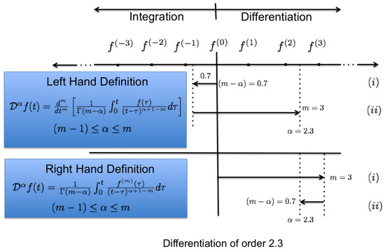
Figure 3.
Fractional order calculus definitions.
Again, the reason that Caputo definition is also called RHD can be visualized from Figure 3. Here, we will focus on Caputo’s definition, which many engineering applications refer to, since it allows the formulation of initial conditions in a form involving only the values of integer order derivatives such as and .
Most natural phenomena can be modeled and explained more accurately by a fractional order differential equation. Consequently, many researchers, scientists, and engineers have been attempting to incorporate fractional calculus into their applications. For more fractional calculus definitions such as those by Abel, Fourier, and Cauchy, see [8,9,10].
The first fractional order controller to appear in the literature is called the Tilt-Integral-Derivative (TID) controller [11]. The TID controller is the modified version of the conventional PID controller where the proportional term is replaced by the transfer function and n is a nonzero real number, preferably between 2 and 3. The aim of the TID controller is to provide more degrees of freedom to tilt or shape the open loop frequency response closer to the theoretically optimal response as mentioned in Bode’s work. The benefits of the TID controller over the conventional PID controller is illustrated in [11].
In 1999, Podlubny [9] introduced a fractional order PID (FOPID) controller where the orders of the derivative and integral terms are any real numbers. Podlubny’s work shows that this type of controller outperforms the conventional PID controller. More details of the structure and characteristics of the FOPID controller will be explained in Section 2.2.
Applications of fractional calculus in control are numerous. In [12], the control of viscoelastic damped structure is presented. Control applications to a flexible transmission [13], an active suspension [14], a buck converter [15], a robotic manipulator [16], and a thermal system [17] are also found in the literature. For AMB system applications, there have also been a few works that make use of the fractional calculus concept. In [18,19], the simplified model of eddy current losses in non laminated magnetic bearing is derived. The transfer function that represents the effective force after taking eddy current losses into account can be expressed as
where is the force input from the actuator, c is the coefficient of the total reluctance, and is the static value of the effective reluctance. This analytical model takes less time to obtain compared to the finite element method that is typically used for analysis. Moreover, this transfer function can be used directly for controller design. In the AMB control design in [20], the fractional order PID controller is designed to stabilize the AMB system by using the Particle Swarm Optimization (PSO) method to minimize the integral of time absolute error (ITAE) criterion. Other AMB control research can be found in [21], where the fractional order PID controller is designed by using the Genetic Algorithm (GA) to minimize overshoot, rise time, cumulative error, and control energy. The results reported in [20,21] show that FOPID control outperforms the conventional PID control in terms of tracking errors and disturbance rejection. However, the designs of fractional order controller for AMB systems in both cases are only for the zero speed case. Furthermore, having only time domain specifications are not enough to guarantee the robustness requirement specified in the API and ISO standards for AMB supported machines [1,22]. Lastly, experimental results of the proposed designs are not available, and the designs have not been validated in an actual application.
2.2. Fractional Order PID Control
Over the years, engineers and industrial practitioners have aspired to substitute the traditional PID controller with a more powerful one. However, the PID controller remains the most popular due to its simplicity and clear physical interpretation of the controller parameters. Recently, there has been an extension of the conventional PID controller by substituting the orders of the derivative and integral components to any arbitrary real numbers instead of fixing those orders to one. The fractional order PID (FOPID) controller was first introduced by Podlubny in 1999 [9]. A block diagram that represents the FOPID control structure is shown in Figure 4. The transfer function of an FOPID controller takes the form of
where λ is the order of the integral part, μ is the order of the derivative part, while , , and are the controller as in a conventional PID controller.
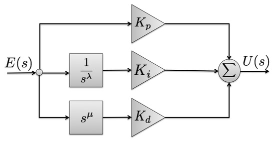
Figure 4.
FOPID block diagram.
2.2.1. Frequency Domain Characteristics
Similar to a conventional PID controller, the FOPID controller behaves as a bandstop filter that passes most frequencies unaltered, but attenuates those in a specific range to very low levels. Generally, the integral part in the conventional PID control helps to eliminate the steady state error due to its infinite gain at zero frequency but it has 90° phase lag. On the other hand, the derivative part provides 90° phase lead, but has a large gain at high frequencies, which is susceptible to noise. By changing the derivative and the integral order in an FOPID controller, one can adjust the sharpness of the filter independently as illustrated in Figure 5. In the frequency domain, the magnitude curve of the fractional derivative and integral terms in the logarithmic scale can be calculated as
and the phase is given by
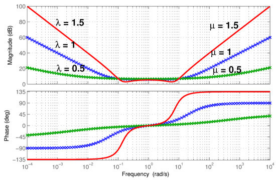
Figure 5.
Frequency domain effects of fractional orders λ and μ.
For the special case when μ and λ are both equal to one, which represents the integer order PID, the slope of the gain becomes −20 dB and the phase of the response is radian in low frequencies. Similarly, the slope of the gain becomes +20 dB and the phase of the response is radian in high frequencies.
Figure 5 confirms that, in the low frequency range, the slope of the gain becomes dB and the phase of the response is radian. In the high frequency range, the slope of the gain becomes +20μ dB and the phase of the response is radian. This shows that the FOPID controller preserves the characteristics of the conventional PID controller with additional flexibility in adjusting the phase and gain at the desired frequencies. This also implies that the FOPID controller, if properly tuned, may have a stronger potential to meet the desired frequency domain specifications of the closed-loop system.
2.2.2. Time Domain Characteristics
In the control design process, another important specification is the transient response performance. Typically, the unit step response is used for the reference input signal in order to show the performances of the closed-loop system. To investigate the effects of fractional derivative and integral order in the FOPID controller, we consider the magnetic levitation system with one degree of freedom from [23], which has the following transfer function
This system has two poles at 64.45 and −62.03, indicating that the system is open loop unstable. Therefore, a Proportional-Derivative (PD) controller is adopted to stabilize the system. For the purposes of stability, the values of and are chosen to be 8.476 and 0.022, respectively. To see the effect of the derivative gain, we inspect the unit step response, shown in Figure 6, as the value of the is varied. It is clear that varying the derivative gain will affect the size of the overshoot of the unit step response. In order to investigate the effect of fractional order derivative, the values of and are fixed to the nominal values and the fractional order μ of the derivative is varied. The unit step response with varying values of μ is shown in Figure 7. It can be seen that varying the value of μ can further reduce the overshoot.
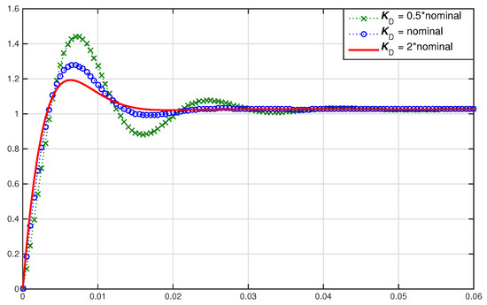
Figure 6.
Time domain effects of the derivative gain.
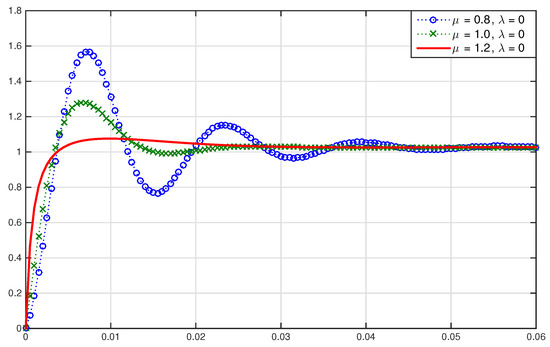
Figure 7.
Time domain effects of the fractional derivative order.
As can be seen in both Figure 6 and Figure 7, the steady state error is not exactly zero. Therefore, an integrator is added. Figure 8 shows the unit step responses with different values of for the integer order PID control with a nominal value of as mentioned above. It can be seen that the steady state errors are eliminated. Also, the responses that converge faster will have higher overshoots. Moreover, Figure 9 shows the unit step responses for different values of λ in the fractional order PID controller with nominal values of and . When λ is changed to 1.4, the overshoot is smaller than the integer order case and the settling time is approximately the same. This shows that varying fractional order derivative can further improve the transient response performances.
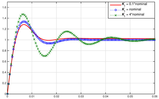
Figure 8.
Time domain effects of the integral gain.
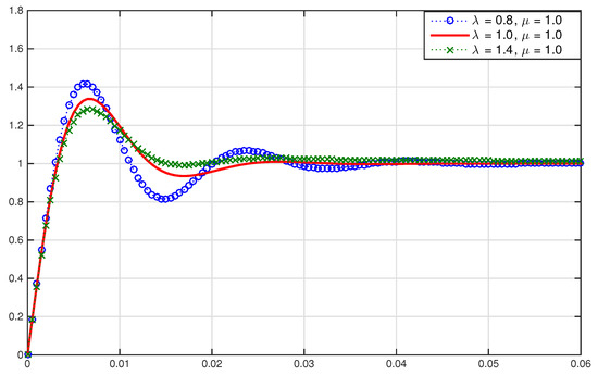
Figure 9.
Time domain effects of the fractional integral order.
For the optimal performance comparison between the integer and fractional PID control in the time domain, the values of the controller gains are fixed to be the same in both the integer and fractional order controllers while the fractional derivative and integral orders are changed to 1.18 and 1.13, respectively. The unit step responses of both cases are shown in Figure 10. It is clearly seen that the transient response performance can be improved significantly by varying the values of the derivative and integral orders.
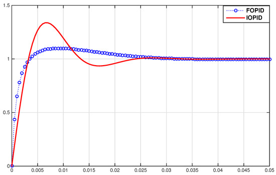
Figure 10.
Step responses under the FOPID and integer order PID (IOPID) controllers.
Essentially, both the frequency and time domain specifications can be improved because FOPID control expands the four discrete control configurations (Proportional (P), Proportional-Integral (PI), PD, and PID) of the conventional PID control to the range of control configurations in the quarter-plane defined by selecting the values of λ and μ as illustrated in Figure 11. Furthermore, the improvement of the transient responses by using FOPID illustrated above is only hand-tuning the parameters. Better results can be expected by fine tuning all five parameters of the FOPID control.
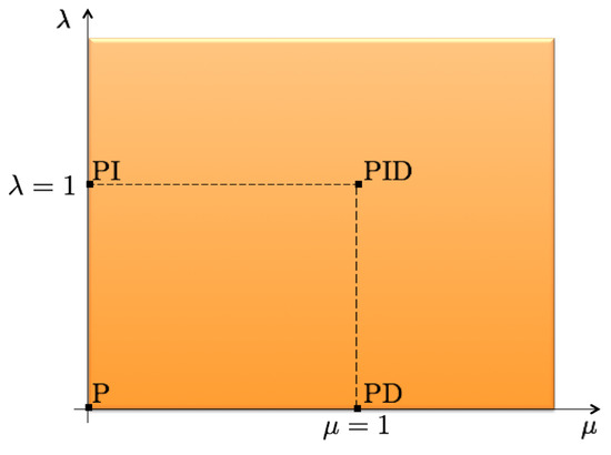
Figure 11.
Parameters in the FOPID control.
2.3. Fractional Order PID Tuning Methods
With the additional flexibility of the fractional derivative and integral orders of FOPID introduced in the previous section, controller parameter tuning is another important factor to pay attention to. There have been tremendous contributions on tuning methods for FOPID controllers in the past years. FOPID tuning methods can be categorized into three main approaches, analytical, rule-based, and numerical tuning methods [24]. The analytical and rule-based methods are widely used in many studies. These methods mainly concern the phase margin, gain margin, gain crossover frequency, and dominant poles. The studies of analytical tuning for FOPID can be found in [25,26,27]. The available rule-based methods can also be extended to the auto-tuning method by incorporating an additional test such as relay feedback test into the loop [28,29].
One of the drawbacks of these two methods is the assumption that a plant is of minimum phase and open loop stable. Because of this limitation, this study will focus only on the numerical tuning method due to the fact that AMB systems are open loop unstable. The aim of numerical tuning methods is to optimize the specified objective functions with respect to the five adjustable parameters (, , , λ, and μ).
2.4. Formulation of the Objective Function
Objective functions used for optimization can be categorized into two types, the time domain and frequency domain objectives.
2.4.1. Time Domain Objectives
Transient response performances with respect to a unit step reference are often used as the time domain objectives in the optimization process. These performances include the overshoot, the rise time, the settling time, and the steady state error. Sometimes, the requirement only emphasizes on a single performance. In this case, the optimization process is usually simple. On the other hand, if two or more performances are set as the objective functions, a conflict may occur during optimization which can cause degradation in some objectives. To deal with these conflicts, performance indices are introduced, in terms of the accumulated error over time, to quantify these performances.
2.4.2. Frequency Domain Objectives
Most studies of numerical tuning methods for FOPID controllers use only time domain objectives. Therefore, the results cannot indicate some important specifications such as robust stability and disturbance rejection capability. These specifications are defined in the frequency domain. Some of the frequently used specifications are
- Sensitivity function:
- Complementary sensitivity function:
- Disturbance sensitivity:
- Control sensitivity:
- Disturbance rejection objective function:
- Control output objective function:
- Robust stability objective function:
- Noise rejection objective function:
Here, and are weighing functions that shape the robust stability and noise rejection performances at the desired frequency.
- Set-point tracking objective function:
Moreover, to guarantee the stability of the closed-loop system, the following condition must be satisfied,
Note that the described time and frequency domain objectives can be combined as a single objective function with different weights on each objective. This allows the optimization problem to be computed in less time. Alternatively, each objective can be optimized individually by using the approach of multi-objective optimization, resulting in an optimal solution for each objective. In this case, additional computing time is required to determine the final optimal solution.
2.4.3. Optimization Algorithms
Many optimization algorithms for control designs have been studied to examine their effectiveness for different purposes. Evolutionary Algorithms (EAs) are one of the most efficient and robust optimization methods. EAs are influenced by the principles of natural selection proposed by Charles Darwin. The idea of “the survival of the fittest" is the key concept behind all evolutionary algorithms [30]. These algorithms are also able to cope with systems that are highly nonlinear, discontinuous, and time-varying. The reason that EAs have become a popular alternative optimization algorithm is that the evolution process enhances the global minimum search whereas conventional optimization algorithms are based on a local gradient search. One of the most popular EAs used in the FOPID control design is the Genetic Algorithm (GA) (see [21,31,32]). Other popular evolutionary algorithms used in the FOPID control design include the particle swarm optimization (PSO) [33,34], the differential evolution (DE) [35,36], and various modifications of the mentioned methods. It is also convenient that all of the mentioned evolutionary algorithms are easily implemented in software.
- Genetic Algorithm (GA)The GA algorithm is the heuristic optimization algorithm influenced by the concept of the population genetics. The following are the steps involved in the algorithm:
- Initialize population: The population of the search is set by converting the controller parameters to binary strings known as chromosomes, where each chromosome represents a possible solution of the problem. Note that the size of the population for each generation is set by the user at the beginning.
- Objective evaluation: Each generated chromosome is evaluated based on the specified objective function.
- Selection: Chromosomes will be selected based on the level of their fitness. The higher fitness level of an individual chromosome, the better chance it will be selected.
- Crossover: The selected chromosomes will randomly exchange some bit(s) to generate the offspring for an evaluation in the next iteration. This process helps expand the possibility of the search space.
- Mutation: The mutation operator will make some small random change to the surviving chromosomes. This process prevents the solutions from being trapped in local minima. Typically, a low mutation rate is chosen, otherwise the search will become totally random.
- Elitism: The best found solution in each generation may be lost in the subsequent generation due to the crossover and mutation processes. Therefore, elitism is introduced to simply copy the best found chromosomes to the next generation. Normally, the number of elites is chosen to be a small fraction of the overall population so that the optimization process is not biased on these solutions.
- Differential Evolution (DE)The DE algorithm is introduced by Storn and Prince in 1995 [37] and is essentially the refined version of the GA with some changes that overcome the disadvantage of the GA. The DE algorithm has an optimization process similar to the GA, except that the DE algorithm uses floating point number instead of bit representation for solution vectors [38]. Therefore, instead of using logical operators used in the GA, the DE algorithm uses arithmetic operators for mutation and crossover processes, which lower the computational complexity and facilitate greater flexibility in the design of the mutation distribution [39]. The optimization step of the DE algorithm is slightly different from the GA and can be summarized as follows:
- Initialize population: The population is initialized randomly and uniformly distributed in the range of the specified lower and upper bound of the variables. The size of the population generated is prescribed by the designer.
- Mutation: First, three solution vectors from the initial population are chosen randomly. Then the donor vector is generated by adding the weighted difference of the first two vectors, and , to the base solution vector , as follows,There are some modifications to let be the best solution from the initial population. Generally, the factor F can vary between 0 and 2, which makes the DE algorithm sensitive to the choice of F. As suggested in [38], a good initial value of F is between 0.5 and 1.
- Crossover: To increase the diversity of the population, the donor vector exchanges its components with the base vector to form the trial vector with the crossover probability . The range of is between 0 and 1, where the value of equals to 1 means that all components of the donor vector are replaced by the base vector . The initial good guess of value is 0.5 in order to maintain the diversity of the population.
- Selection: At this stage, the trial vector is evaluated. If the trial vector yields the lower value of the objective function, then it replaces the corresponding base vector in the next generation. Otherwise, the base vector is retained in the population. Hence, the population either gets better or remains the same (with respect to the minimization of the objective function), but never deteriorates.
The process is iterated and terminated when a specified number of iterations is exceeded or the value of the objective function falls below a prescribed value. For more variations of the mutation and crossover scheme, see [38]. - Particle Swarm Optimization (PSO)The PSO algorithm is a population-based stochastic optimization technique developed by Eberhart and Kennedy in 1995 [40]. The method is inspired by the social behavior of bird flocking, fish schooling, etc. Unlike the GA and DE algorithms that use the concept of the fittest to survive, the PSO algorithm uses the particles that constitute a swarm to move around the prescribed space in order to find the best solution. Each particle adjusts its position based on its experience from previous iterations as well as the experience of other particles. The two important values used for adjusting the moving direction in the concept of PSO are the best solution of each particle (pbest) and the best solution of the entire swarm (gbest). The searching algorithm to calculate the new position of each particle based on pbest and gbest is described in the following equations:where is the velocity of particle j at iteration t, with j = 1,2,…,n, N = 1,2,…,m, and
- -
- n is the number of particles (population size);
- -
- m is the dimension of the problem (number of variables);
- -
- , are the acceleration factors;
- -
- , are the uniformly distributed numbers between 0 and 1.
where is the maximum number of iterations and iter is the current iteration number.
2.5. Fractional Order PID Controller Implementation
A feasible way to implement a fractional order operator is to use a finite dimensional integer order transfer function, which requires approximation. The fractional order operator can be approximated in both continuous time and discrete time. This work will focus on continuous time approximation because the result of approximation in continuous time is more suitable for further analysis.
One of the well-known approximation methods is proposed by Oustaloup [41]. Oustaloup’s approximation of fractional order α in the specified frequency range [] is given as
where N is the number of poles and zeros which is chosen beforehand and the accuracy of the approximation strongly depends on this number. Then, the zeros, poles, and gain are evaluated as
For the case , the right hand side of Equation (15) will be inverted. But if , the approximation becomes unsatisfactory. Accordingly, it is usual to split the fractional power of s into the following form
where n is an integer number, , and [0,1]. In this manner, only the term needs to be approximated.
It has been proven that this approximation method is accurate enough for the implementation purpose [42]. Modified versions of Oustaloup’s approximation can be found in [43,44].
Additionally, attempts have also been made for analog realizations of a fractional order controller by using a combination of resistors, inductors, and capacitors [45,46]. However, modifications are difficult to be made on analog devices.
3. System Description and Modelling
3.1. Overview of the Test Rig
For the purpose of investigating the capability of AMBs in high-speed compressor applications, the single-stage centrifugal compressor equipped with AMBs was built and commissioned in the Rotating Machinery and Control Laboratory (ROMAC) at the University of Virginia, as shown in Figure 12 and Figure 13. Specifically, this test rig is used as a platform to demonstrate flow instabilities caused by surge in a centrifugal compressor. The rotor is levitated by two radial AMBs for smooth rotation without mechanical contact. The rotor is supported axially by the thrust AMB, which is also used to modulate the impeller tip clearance for the purpose of surge control. The designed maximum operational speed is 23,000 rpm, which requires a power supply of 52 kW. Within the operating speed range (maximum at 23,000 rpm), the rotor is considered to be a rigid rotor since the first bending mode is at 40,792 rpm. The rotor has a length of 0.517 m and is 27 kg in mass. AMBs used for radial suspension are 12 pole E-core design. The 12 poles are separated into four quadrants. The width of the primary and secondary poles are 27.94 mm and 13.97 mm, respectively. Each pole has 51 turns of 17 AWG wire. The stators of the radial AMBs are laminated in order to reduce the eddy current effect. The designed maximum load capacity per quadrant is 1414 N and the nominal air gap is 0.5 mm. The corresponding values of negative stiffness and current gain were obtained experimentally and summarized in Table 1. The instrumentation properties are summarized in Table 2.
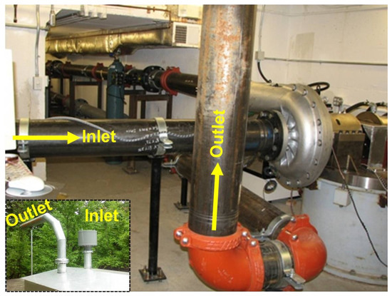
Figure 12.
The compressor and piping system.
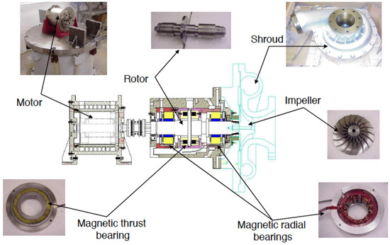
Figure 13.
Components of the centrifugal compressor.

Table 1.
AMB properties.

Table 2.
Instrumentation properties.
3.2. Rotor Lateral Dynamics
The rotor lateral dynamics can be represented as the block diagram shown in Figure 14, where the rotor model is derived by the finite element analysis. The values of negative stiffness and current gain are summarized as mentioned in Section 3.1.

Figure 14.
Rotor-AMB system block diagram.
The complete radial AMB system combines the rotor-AMB model with the power amplifiers, sensors, and time delay models as shown in Figure 15. The control output voltage is the input to the system and the sensor measurement voltage is the output of the system. A time delay is also added to complete the model in order to represent the sampling and computational delays that occur in the digital controller.

Figure 15.
Radial AMB system block diagram.
3.3. Rotor Axial Dynamics
The rotor axial dynamics can be simply represented as a single mass, and the equation of motion is
where is the rotor mass, is the axial acceleration, and is the axial external force acting on the rotor. As mentioned in Section 3.1, laminations are not practical to manufacture for the thrust AMB. This means that the eddy current losses need to be included. The eddy current loss model was proposed by Zhu et al. in [18]. The transfer function that represents the effective force after taking eddy current losses into account can be expressed as
where is the force input from the actuator, c is the coefficient of the total reluctance, and is the static value of the effective reluctance. For simplicity in the design process, the effective force is approximated to integer order form. The rotor-AMB model in the axial direction can be represented as the block diagram in Figure 16, where represents an amplifier with bandwidth . The more complete thrust AMB model is constructed the same way as illustrated in Figure 15.

Figure 16.
Thrust AMB system block diagram.
4. Fractional Order Control of Rotor Suspension
4.1. Control Design Specifications
A commonly used rotor-dynamic specifications of AMB systems are developed by American Petroleum Institute (API) and International Organization for Standardization (ISO). The specifications are developed based on the API 617 [22], which is for centrifugal compressors equipped with traditional rolling element or fluid-film bearings. Since the clearance available in the AMB system is larger than the clearance in machines equipped with traditional rolling element or fluid-film bearings, the standard includes a section on machines equipped with magnetic bearings. This additional section states that the maximum vibration must be lower than 30% of the minimum clearance . In AMB systems, usually refers to the clearance relative to the center of auxiliary bearing. Moreover, the forced response analysis with different locations of unbalance mass placement is also used for AMB systems. Unbalance values and locations for different modes are illustrated in Figure 17. This analysis is used to predict the amount of vibration when each mode is excited according to the placement of unbalance values. Unbalance values and locations for different modes are illustrated in Figure 17, where U is the unbalance force, N is the maximum continuous operating speed (rpm), and W is the static journal load (kg).
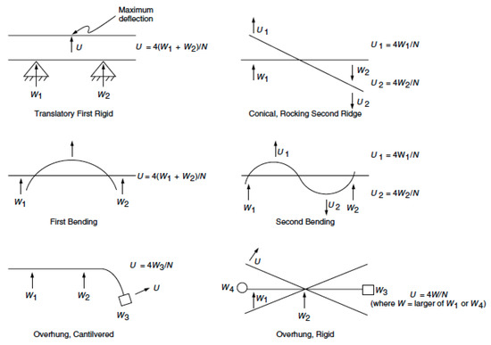
Figure 17.
Unbalance values and locations as specified in API 617 [22].
Another set of widely used specifications for AMB systems is stated in ISO 14839 [1,47,48]. This standard is used as a recommended specification instead of as a requirement. Vibration level and stability margin are the two specifications recommended in ISO 14839. The stability margin is determined by the peak value of sensitivity function. This margin implies how sensitive the system response is to variations in the system. As illustrated in Figure 18, the sensitivity function is defined as the transfer function either from disturbance to controller input () or from disturbance to plant input (). The specifications categorize the system into Zone A through D depending on the maximum displacement and peak value of the sensitivity function as summarized in Table 3. At the present, ISO 14839 is merged in as one of the sections in API 617 [22].
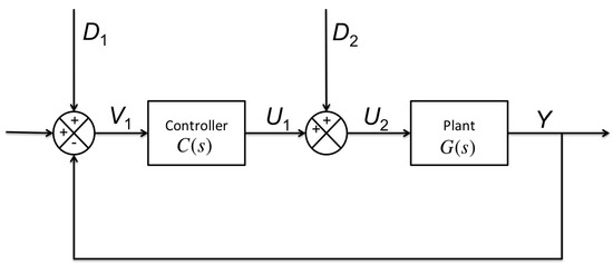
Figure 18.
Closed-loop system block diagram with disturbances.

Table 3.
Recommended criteria of zone limits in ISO 14839 [47,48].
The definitions of the zones are described as follows.
- Zone A: newly commissioned machines normally fall into this zone
- Zone B: acceptable for unrestricted long-term operation
- Zone C: unsatisfactory for long-term continuous operation
- Zone D: sufficiently severe to cause damage to the machine
Another control design specification that is used widely in most control system designs is the transient response performance. These performance parameters show how smooth the operation could be in case there are external disturbances. Typically a unit step response test is performed to demonstrate this specification. The performances considered in the step response test are the rise time, the settling time, and the overshoot.
4.2. Design and Experimental Test of FOPID Controller for Rotor Lateral Dynamics
4.2.1. Design of FOPID Controller
The FOPID controller for the rotor lateral dynamics takes the form as illustrated in Equation (8). This controller is also coupled with a second order low-pass filter in order to limit the bandwidth as well as to make the controller realizable for implementation. Here it is assumed that the two control axes (x and y) are symmetric. Therefore, the controllers used for both control axes will be identical.
Within this study, all controller parameters are tuned using the Genetic Algorithm (GA), the Differential Evolution (DE) algorithm and the Particle Swarm Optimization (PSO) algorithm. The first step in the tuning process is to specify the objective functions. As previously mentioned, the vibration level and the stability margin are the two main specifications. Furthermore, the step response performance objective is also important to include in order to provide smooth rotation during the transition between rotational speeds and an ability to reject disturbances. Thus, the objective functions used for the control of the rotor lateral dynamics are listed below.
- Stability of closed-loop system (): Closed-loop stability will be determined by the number of poles that have a positive real part. The optimization goal of this objective is zero.
- Stability margin (): A peak magnitude of the sensitivity function as described in Section 2.4 will be used to determine a stability margin.
- Vibration level (): A maximum magnitude of forced responses among three cases (translate mode, conical mode, and overhung cantilevered) as illustrated in Figure 17. This objective will be used to determine the maximum vibration.
- Integral square error (ISE) of a unit step response (): Instead of specifying transient response performance separately, the performance index ISE will be used in order to reduce conflict between different performances.
All objective functions will be combined as a single cost function J during the optimization process. Therefore, it is proper to add some constant weights, , for each specified objective so that all weighted objectives are normalized,
These constant weights are the inverse of the desired values of each specification. For example, the desired value of peak sensitivity must be less than 3 according to the ISO specification, thus the initial value of is 1/3.
Next, the parameter values of the GA optimization must be initialized. These values include the size of the population, the initial population values, the crossover rate, and the mutation rate. The selected size of the population reflects the total tested solutions for each generation. A larger population can lead to better minimization results, but the computation will be longer. For this study, the population size is chosen to be 200. The initial population consists of the gains and orders of the FOPID controller. These initial values are obtained from the manual tuning of the conventional PID controller for the system, which means that the initial derivative and integral orders are set to 1. The closed-loop system is stable with these initial values, which can reduce the load on the stability objective during the optimization process. The value of the crossover rate is 0.8 and the uniform mutation rate is 0.01. After 50 generations, the optimization is completed. The whole process will be repeated with the new initial populations based on the solution from the previous iteration. There may be slight changes in the lower and upper bounds of the tuning parameters as well. Normally, after 3 to 5 iterations, the improvement of the solution will be very small.
Note that the main difference of this study from the existing works in the field is that the approximation of the fractional order operators, and , occur during the tuning process. Studies in the past generally have addressed the approximation step after the optimization is completed, which can degrade the performance of the FOPID controller due to errors from the approximation. Therefore, in this study, the approximation is included in the optimization process and uses the approximated FOPID controller to evaluate all objective functions. Oustaloup’s method is used for the fractional order approximation as explained in Section 2.5 and the chosen number of poles and zeros used for the approximation is 2.
For the next design, the FOPID controller will be designed based on two additional tuning methods. First the DE tuning method is employed in the design process. As described in Section 2.4.3, parameters needed for the optimization process are similar to the GA algorithm except for the weight factor F for the mutation process, which is set to be 0.85 in this study. Otherwise, the size of population, the number of maximum iterations, and the crossover rate remain the same as in the GA optimization case. Second, the FOPID controller parameters are tuned by the PSO tuning method. The size of the population and the maximum iterations are the same as in the two previous methods. The acceleration factors and are set to be 0.5 and 1.25, respectively. The value of is set to be greater than so as to assign heavier weight to the acceleration rate for the global best solution in each generation.
The performance of the FOPID controllers tuned by the GA, DE, and PSO methods are summarized in Table 4 and the Bode plots of the sensitivity functions of the resulting FOPID controllers are illustrated in Figure 19. It can be observed that the FOPID controller tuned by the DE algorithm gives better results in terms of the peak of the sensitivity function and maximum vibration levels. In addition, the corresponding FOPID controller has a good transient response for a smooth rotation. Therefore, this FOPID controller will be used for implementation as well as for comparison with other kinds of controllers.

Table 4.
Comparison of performances of the FOPID controllers tuned by different evolutionary algorithms.
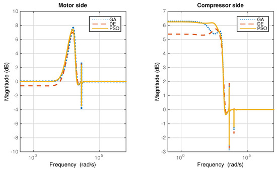
Figure 19.
Magnitude plots of the sensitivity functions of the FOPID controllers with different tuning algorithms.
To emphasize the best case of the FOPID controller design, Table 5 summarizes the values of the FOPID controller parameters obtained from the DE optimization. The vibration levels and the stability margins, measured at the the AMB locations at the motor side (MS) and the compressor side (CS), are shown in Figure 20 and Figure 21, respectively. The vibration level is well below 30% of the minimum clearance. The peak of the sensitivity function over the rotational speed range is below a magnitude of 3. This shows that the Zone A specification as recommended by ISO 14839 is satisfied by the FOPID controller.

Table 5.
Parameters in the FOPID controllers tuned by the DE algorithm.
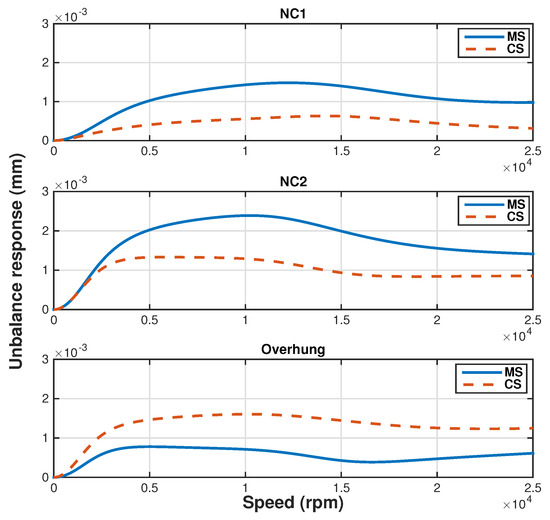
Figure 20.
Forced response with unbalance mass placing for three excitation cases as specified in API 617 [22].
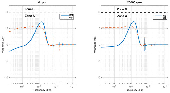
Figure 21.
Magnitude plots of the sensitivity functions at zero and maximum continuous speed under the FOPID controllers tuned by the DE algorithm.
For comparison, the conventional PID controller is tuned based on the same objectives and algorithms as for the FOPID controller. Moreover, performances based on the LQG controller that were designed for the same system reported in [49] are compared with both the FOPID and PID controllers in Table 6.

Table 6.
Comparison of performances in radial AMBs.
As shown in Table 6 and Figure 22, the stability margin of all controllers fall within Zone A specification (smaller than 3). Moreover, the sensitivity function peak of the FOPID controller is smaller than the value achieved by the PID and LQG controllers. Another advantage of the FOPID controller over the LQG controller is the reduction of the controller size by 50 percent. Transient response of each controller is approximately the same. Each controller has a bandwidth within the limit for digital implementation at a 5 kHz sampling frequency.
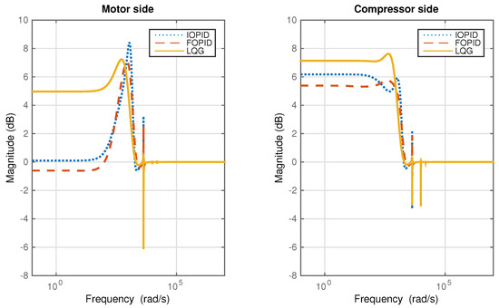
Figure 22.
Bode plots of the lateral AMB sensitivity function at the motor side and compressor side under three different controllers.
4.2.2. Experimental Test of Lateral Rotor Suspension
To validate the design of the FOPID controller for lateral rotor dynamics in the previous section, two types of measurements are made. The first type of measurement is the rotor vibration magnitude for speeds ranging from 500 rpm to 16,500 rpm, in 500 rpm increments. Three separate cases are tested including the conventional integer order PID (IOPID) and FOPID controllers tuned by the DE algorithm and the LQG controller that was previously designed in [49].
The results in Figure 23 and Figure 24 show the rotor vibration within the specified speed range of the motor side and compressor side, respectively. The FOPID controller leads to the smallest vibration magnitude throughout the speed range among all three tested controllers and its peak magnitude is well within the limit of Zone A specified by ISO [47]. The IOPID controller leads to the largest vibration magnitude which can be observed from the motor side measurement. The result agrees with the prediction of the maximum vibration magnitudes tested in the forced response analysis.
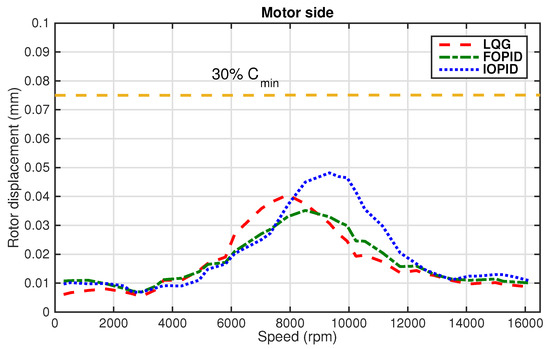
Figure 23.
Rotor displacements at the motor side under the IOPID, FOPID, and LQG controllers.
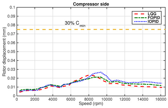
Figure 24.
Rotor displacements at the compressor side under the IOPID, FOPID, and LQG controllers.
The second test is the sensitivity function frequency response measurement. Again, the three controllers used in the rotor vibration experiment are tested. For this testing, the perturbation signal of 100 mv with frequencies ranging from 0.1 Hz to 1200 Hz is added at the controller input and the sensitivity function frequency response is obtained from the relationship between the sum of perturbation and controller input signals and the perturbation signal itself. The frequency response plots for the cases of all three controllers for both the motor side and the compressor side are shown in Figure 25 and Figure 26, respectively. From these results, the sensitivity function peak under the FOPID controller is the smallest and falls into Zone A specification of the ISO standard [48], while the IOPID controller results in the largest sensitivity function peak and its magnitude falls into Zone B specification. Lastly, the trend of the sensitivity function frequency responses match the theoretical prediction in Figure 22.
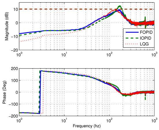
Figure 25.
Bode plots of the lateral AMB sensitivity function at the motor side.
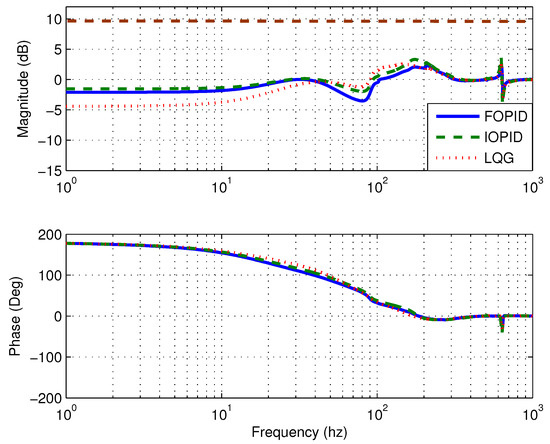
Figure 26.
Bode plots of the lateral AMB sensitivity function at the compressor side.
4.3. Design and Experimental Test of FOPID Controller for Rotor Axial Dynamics
4.3.1. Design of FOPID Controller
The ultimate goal of the control design for the thrust AMB system is to achieve good rotor tracking performance at a low/mid frequency range. In addition, the closed-loop system should have a capability to reject external disturbances such as aerodynamic disturbances acting on the compressor impeller during surge. The designed controller with these capabilities must have a bandwidth within the range limited by the sampling frequency. The controller structure will have the same form as in the lateral dynamics design, where the FOPID controller is coupled with a second order low pass filter. The objective functions will be similar to the objectives defined for the controller design for axial rotor support in [49]. The objective functions will combine the weighting functions with the sensitivity function S, the complementary sensitivity function T, the plant transfer function G, and the controller transfer function K, in order to specify the desired performance in the frequency domain. All these objective functions are listed below.
- Stability of the closed-loop system (): Closed-loop stability will be determined by the number of poles that have positive real part. The optimization goal of this objective is zero.
- Tracking error performance:
- Control effort according to the reference input signal:
- Transmission of the input disturbance to the control output:
- Closed-loop dynamics from the reference input to the rotor position: .
In the above objective functions, the weighting functions are defined in [49], based on the interconnected system shown in Figure 27, as follows,
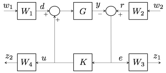
Figure 27.
Interconnected system for the design of the thrust AMB rotor support controller.
Similar to the previous design, all objective functions will be combined as a single cost function during the optimization process as follows,
The optimization goal is to have the infinity norm of all objective functions smaller than 1. Once again, the three tuning methods used for the optimization are the GA, DE, and PSO methods. The size of the population for all cases is reduced to 100 since there are fewer tuned parameters than the control of rotor lateral dynamics. The crossover rate, the weight factor, the acceleration rate, and the mutation rate are kept the same as in the previous design. Table 7 shows the resulting infinity norm of the objective functions for all tuning methods. All tuning methods have similar optimization results. Yet, the DE algorithm achieves the lowest infinity norm. Thus, this design will be used for implementation.

Table 7.
Comparison of the objective function peaks resulting from different tuning methods.
Table 8 summarizes the values of the FOPID controller parameters obtained from the DE optimization. The resulting magnitude plots of all objectives, except the stability objective, are shown in Figure 28.

Table 8.
The tuned FOPID controller parameters for rotor axial dynamics.
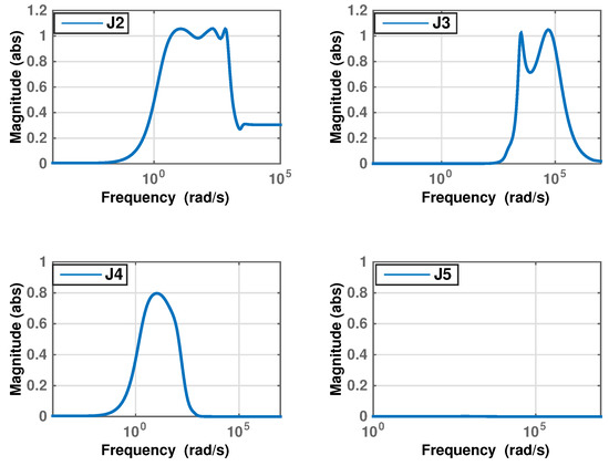
Figure 28.
Magnitude of the objective functions under the FOPID controller.
The sensitivity function in Figure 29 shows that the stability margin specification qualifies for Zone A, where a sensitivity peak is less than 3. Besides the peak of the sensitivity function, tracking error performance can also be observed from the magnitude of the complementary sensitivity function T, which represents the relationship between the reference input and the rotor position. Figure 29 shows that, at low/mid frequencies the magnitude of T is 1 and the phase is 360° (in phase). This implies that the rotor position follows the change of the input reference signal closely in that frequency range.
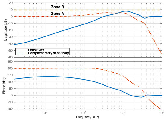
Figure 29.
Bode plots of the thrust AMB sensitivity and complementary sensitivity functions under the FOPID controller tuned by the DE algorithm.
For comparison, the conventional PID controller is tuned based on the same objectives and algorithms as the FOPID controller. Moreover, performance based on the controller that was designed for the same system reported in [49] are compared with both the FOPID and the IOPID controllers in Table 9.

Table 9.
Comparison of performances in the thrust AMB system.
In Table 9, both the FOPID and the controllers achieve a stability margin to satisfy the Zone A requirement. On the other hand, the stability margin falls into Zone B when using a PID controller as shown in Figure 30. Moreover, the sensitivity function peak under the FOPID controller is close to the value achieved by the controller. The advantage of the FOPID controller over the controller is that the dimension of the controller is reduced by 50 percent. Lastly, all controllers have a bandwidth within the limit for the digital implementation of 5 kHz sampling frequency.
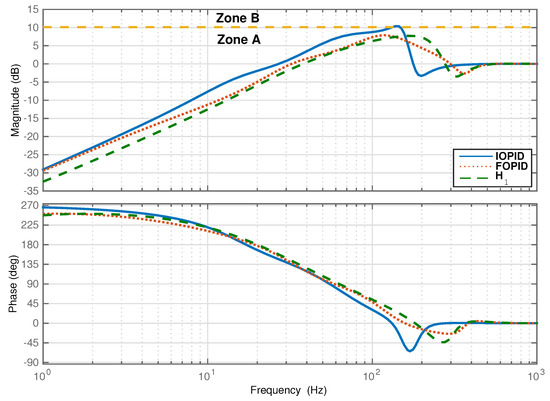
Figure 30.
Bode plots of the thrust AMB sensitivity and complementary sensitivity functions.
4.3.2. Experimental Test of Axial Rotor Suspension
The sensitivity function frequency response measurement is conducted the same way as in the lateral rotor dynamics case. The frequency response plots of all three controllers are shown in Figure 31. From these results, the sensitivity function peak under the FOPID controller is the smallest and falls into Zone A specification of the ISO standard [48], while the IOPID controller has the largest sensitivity function peak and its magnitude falls into Zone B specification. The trend of the sensitivity function frequency responses matches the theoretical prediction in Figure 30. Figure 32 shows that the closed-loop bandwidth when using the FOPID controller matches the simulation result.
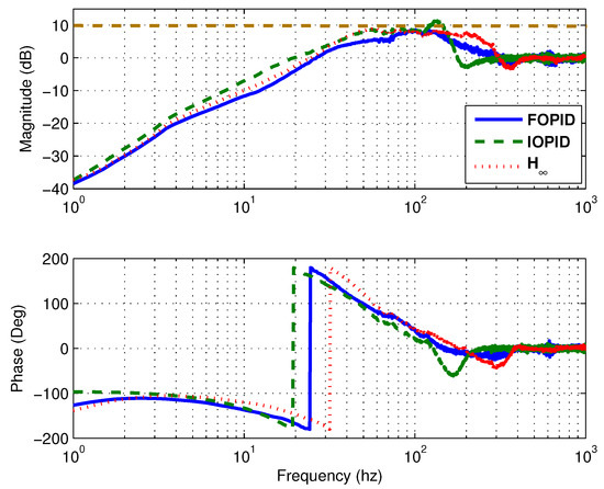
Figure 31.
Bode plots of the thrust AMB sensitivity function.
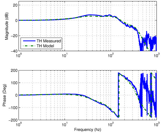
Figure 32.
Bode plots of the thrust AMB sensitivity function under the FOPID controller.
5. Discussion
With the specified control objectives that are based on the accepted industrial standards for machinery equipped with magnetic bearings, including ISO 14839 and API 617, the FOPID controllers are designed for rotor suspension in both the radial and the axial directions.
For the rotor lateral dynamics, the control objectives include the peak of the sensitivity function, the rotor vibration caused by the unbalanced forces, and the transient response performance. The design begins with the determination of whether to use the centralized or the decentralized control structure. The simulation results reveal that the centralized control structure provides better performance. Afterward, three tuning methods namely, the Genetic Algorithm (GA) method, the Differential Evolution (DE) method, and the Particle Swarm Optimization (PSO) method, are investigated for their effectiveness for the FOPID controller design. The results show that the DE method achieves the best performance. For comparison, the IOPID controller is designed based on the centralized structure and tuned by the DE optimization method. Moreover, the designed and implemented LQG controller reported in [49] is also compared with the designed FOPID controller. The experimental results for rotor vibration with the rotor spinning at speeds ranging from 500 rpm to 16,500 rpm show that the FOPID results in the smallest rotor vibration and the IOPID results in the largest vibration peak, while the rotor vibration under the LQG controller falls in between the results under the FOPID and the IOPID controllers. In addition, in terms of the peak value of the sensitivity function, the FOPID controller results in the smallest and it falls into Zone A specified by the ISO standard, while LQG controller also achieve the Zone A specification with a slightly larger peak value of the sensitivity function than the FOPID controller. On the other hand, the IOPID controller can achieve only Zone B specification.
For the rotor axial dynamics, the FOPID controller is designed based on the objectives specified by weighting functions developed in the previous work [49]. Three different tuning methods are investigated. The results show that the DE method can achieve the best performance as in the previous design. For comparison, the IOPID controller is designed based on the same objectives and the same optimization algorithm as the FOPID controller. Moreover, the designed controller for the rotor axial dynamics in [49] is also analyzed for comparison. Finally, the experimental results show that the FOPID controller achieves approximately the same value of the sensitivity function peak as achieved by controller, and once again their performance falls into Zone A specification. In contrast, the value of the sensitivity function peak under the IOPID controller exceeds the Zone A level.
Based on the simulation and experimental results presented in Section 4, if properly tuned, the FOPID controller designed for the rotor suspension outperforms the IOPID controller with only the variation of the integral and derivative orders. Furthermore, the FOPID controller can achieve performance similar to or even better than advanced controllers such as LQG and , while the controller structure as well as the design process of the FOPID are simpler.
Author Contributions
P.A. and Z.L. formulated the problem; P.A. and Z.L. conceived and designed the experiments; P.A. performed the experiments; P.A. and Z.L. analyzed the data; P.A. and Z.L. prepared the manuscript.
Conflicts of Interest
The authors declare no conflict of interest.
References
- International Organization for Standardization (ISO). ISO14839-1: Mechanical Vibration—Vibration of Rotating Machinery Equipped With Active Magnetic Bearings—Part 1: Vocabulary; ISO: Geneva, Switzerland, 2002. [Google Scholar]
- Schweitzer, G.; Maslen, E.H. Magnetic Bearings; Springer: Berlin/Heidelberg, Germany, 2009. [Google Scholar]
- Grega, W.; Pilat, A. Comparison of linear control methods for an AMB system. Int. J. Appl. Math. Comput. Sci. 2005, 15, 245–255. [Google Scholar]
- Jastrzebski, R.P.; Hynynen, K.M.; Smirnov, A. H∞ control of active magnetic suspension. Mech. Syst. Signal Process. 2010, 24, 995–1006. [Google Scholar] [CrossRef]
- Fittro, R.L.; Knospe, C.R. Control of a high speed spindle thrust magnetic bearing. In Proceedings of the IEEE International Conference on Control Applications, Kohala Coast, HI, USA, 22–27 August 1999; pp. 570–575.
- Das, S. Functional Fractional Calculus; Springer: Berlin/Heidelberg, Germany, 2011. [Google Scholar]
- Folland, G.B. Advanced Calculus; Pearson Education India: Karnataka, India, 2002. [Google Scholar]
- Oldham, K.B.; Spanier, J. The Fractional Calculus: Theory and Applications of Differentiation and Integration to Arbitrary Order; Academic Press: New York, NY, USA, 1974; Volume 111. [Google Scholar]
- Podlubny, I. Fractional Differential Equations: An Introduction to Fractional Derivatives, Fractional Differential Equations, to Methods of Their Solution and Some of Their Applications; Academic Press: San Diego, CA, USA, 1998; Volume 198. [Google Scholar]
- Ross, B. Fractional Calculus and Its Applications; Springer: Berlin, Germany, 1975. [Google Scholar]
- Lurie, B. Tunable TID Controller. US Patent No. 5,371,670, 6 December 1994. [Google Scholar]
- Bagley, R.L.; Calico, R. Fractional order state equations for the control of viscoelastically damped structures. J. Guid. Control Dyn. 1991, 14, 304–311. [Google Scholar] [CrossRef]
- Oustaloup, A.; Mathieu, B.; Lanusse, P. The crone control of resonant plants: Application to a flexible transmission. Eur. J. Control 1995, 1, 113–121. [Google Scholar] [CrossRef]
- Aldair, A.A.; Wang, W.J. Design of fractional order controller based on evolutionary algorithm for a full vehicle nonlinear active suspension systems. Int. J. Control Autom. 2010, 3, 33–46. [Google Scholar]
- Calderon, A.J.; Vinagre, B.M.; Feliu, V. Fractional order control strategies for power electronic buck converters. Signal Process. 2006, 86, 2803–2819. [Google Scholar] [CrossRef]
- Ferreira, N.F.; Machado, J.T. Fractional-order hybrid control of robotic manipulators. In Proceedings of the 11th International Conference on Advanced Robotics (ICAR 2003), Coimbra, Portugal, 30 June–3 July 2003; pp. 393–398.
- Gabano, J.-D.; Poinot, T. Fractional modelling and identification of thermal systems. Signal Process. 2011, 91, 531–541. [Google Scholar] [CrossRef]
- Zhu, L.; Knospe, C.R.; Maslen, E.H. Analytic model for a nonlaminated cylindrical magnetic actuator including eddy currents. IEEE Trans. Magn. 2005, 41, 1248–1258. [Google Scholar]
- Knospe, C.R.; Zhu, L. Performance limitations of non-laminated magnetic suspension systems. IEEE Trans. Control Syst. Technol. 2011, 19, 327–336. [Google Scholar] [CrossRef]
- Khandani, K.; Jalali, A.A. PSO based optimal fractional PID controller design for an active magnetic bearing system. In Proceedings of the 18th Annual International Conference of Mechanical Engineering, Tehran, Iran, 11–13 May 2010.
- Chang, L.Y.; Chen, H.C. Tuning of fractional PID controllers using adaptive genetic algorithm for active magnetic bearing system. WSEAS Trans. Syst. 2009, 8, 158–167. [Google Scholar]
- American Petroleum Institute (API). API 617: Axial and Centrifugal Compressors and Expander-Compressors for Petroleum Chemical and Gas Industry Services, 8th ed.; API: Washington, DC, USA, 2014. [Google Scholar]
- Hypiusova, M.; Osusky, J. PID controller design for magnetic levitation model. In Proceedings of the International Conference Cybernetics and Informatics, Vyšná Boca, Slovak, 10–13 February 2010.
- Valerio, D.; da Costa, J.S. A review of tuning methods for fractional PID. In Proceedings of the 4th IFAC Workshop on Fractional Differentiation and Its Applications, FDA, Badajoz, Spain, 18–20 October 2010.
- Caponetto, R.; Fortuna, L.; Porto, D. A new tuning strategy for a non integer order PID controller. In Proceedings of the First IFAC Workshop on Fractional Differentiation and Its Application, Bordeaux, France, 19–21 July 2004; pp. 168–173.
- Zhao, C.; Xue, D.; Chen, Y.Q. A fractional order PID tuning algorithm for a class of fractional order plants. In Proceedings of the 2005 IEEE International Conference Mechatronics and Automation, Niagara Falls, ON, Canada, 29 July–1 August 2005; pp. 216–221.
- Maione, G.; Lino, P. New tuning rules for fractional PID controllers. Nonlinear Dyn. 2007, 49, 251–257. [Google Scholar] [CrossRef]
- Vinagre, B.M.; Monje, C.A.; Calderon, A.J.; Suarez, J.I. Fractional PID controllers for industry application. A brief introduction. J. Vib. Control 2007, 13, 1419–1429. [Google Scholar] [CrossRef]
- Monje, C.A.; Vinagre, B.M.; Feliu, V.; Chen, Y. Tuning and auto-tuning of fractional order controllers for industry applications. Control Eng. Pract. 2008, 16, 798–812. [Google Scholar] [CrossRef]
- Fleming, P.J.; Purshouse, R.C. Evolutionary algorithms in control systems engineering: A survey. Control Eng. Pract. 2002, 10, 1223–1241. [Google Scholar] [CrossRef]
- Chang, F.-K.; Lee, C.-H. Design of fractional PID control via hybrid of electromagnetism-like and genetic algorithms. In Proceedings of the Eighth International Conference Intelligent Systems Design and Applications (ISDA08), Kaohsiung, Taiwan, 26–28 November 2008; pp. 525–530.
- Cao, J.-Y.; Liang, J.; Cao, B.-G. Optimization of fractional order PID controllers based on genetic algorithms. In Proceedings of the 2005 International Conference Machine Learning and Cybernetics, Guangzhou, China, 18–21 August 2005; pp. 5686–5689.
- Bingul, Z.; Karahan, O. Tuning of fractional PID controllers using PSO algorithm for robot trajectory control. In Proceedings of the 2011 IEEE International Conference Mechatronics (ICM), Istanbul, Turkey, 13–15 April 2011; pp. 955–960.
- Cao, J.-Y.; Cao, B.-G. Design of fractional order controllers based on particle swarm optimization. In Proceedings of the 2006 1ST IEEE Conference Industrial Electronics and Applications, Singapore, 24–26 May 2006; pp. 1–6.
- Biswas, A.; Das, S.; Abraham, A.; Dasgupta, S. Design of fractional-order PID controllers with an improved differential evolution. Eng. Appl. Artif. Intell. 2009, 22, 343–350. [Google Scholar] [CrossRef]
- Chang, W.-D. Two-dimensional fractional-order digital differentiator design by using differential evolution algorithm. Digit. Signal Process. 2009, 19, 660–667. [Google Scholar] [CrossRef]
- Storn, R.; Price, K. Differential Evolution-A Simple and Efficient Adaptive Scheme for Global Optimization over Continuous Spaces; International Computer Science Institute: Berkeley, CA, USA, 1995. [Google Scholar]
- Price, K.; Storn, R.M.; Lampinen, J.A. Differential Evolution: A Practical Approach to Global Optimization; Springer Science and Business Media: New York, NY, USA, 2006. [Google Scholar]
- Pan, I.; Das, S. Intelligent Fractional Order Systems and Control: An Introduction; Springer: Berlin/Heidelberg, Germany, 2012. [Google Scholar]
- Eberhart, R.C.; Kennedy, J. A new optimizer using particle swarm theory. In Proceedings of the Sixth International Symposium on Micro Machine and Human Science, New York, NY, USA, 4–6 October 1995; pp. 39–43.
- Oustaloup, A. La Commande CRONE: Commande Robuste Dordre Non Entier; Hermes: Paris, France, 1991. (In French) [Google Scholar]
- Oustaloup, A.; Levron, F.; Mathieu, B.; Nanot, F.M. Frequency-band complex noninteger differentiator: Characterization and synthesis. IEEE Trans. Circuits Syst. I Fundam. Theory Appl. 2000, 47, 25–39. [Google Scholar] [CrossRef]
- Xue, D.; Zhao, C.; Chen, Y.Q. A modified approximation method of fractional order system. In Proceedings of the 2006 IEEE International Conference Mechatronics and Automation, Luoyang, China, 25–28 June 2006; pp. 1043–1048.
- Xue, D.; Chen, Y. Suboptimum H2 pseudo-rational approximations to fractional-order linear time invariant systems. In Advances in Fractional Calculus; Springer: Dordrecht, The Netherlands, 2007; pp. 61–75. [Google Scholar]
- Podlubny, I.; Petras, I.; Vinagre, B.M.; Oleary, P.; Dorcak, L. Analogue realizations of fractional-order controllers. Nonlinear Dyn. 2002, 29, 281–296. [Google Scholar] [CrossRef]
- Charef, A. Analogue Realisation of Fractional-Order Integrator, Differentiator and Fractional PID Controller. In IEE Proceedings—Control Theory and Applications; IET: Stevenage, UK, 2006; Volume 153, pp. 714–720. [Google Scholar]
- International Organization for Standardization (ISO). ISO14839-2: Mechanical Vibration—Vibration of Rotating Machinery Equipped With Active Magnetic Bearings—Part 2: Evaluation of Vibration; ISO: Geneva, Switzerland, 2004. [Google Scholar]
- International Organization for Standardization (ISO). ISO14839-3: Mechanical Vibration—Vibration of Rotating Machinery Equipped With Active Magnetic Bearings—Part 3: Evaluation of Stability Margin; ISO: Geneva, Switzerland, 2006. [Google Scholar]
- Yoon, S.Y.; Lin, Z.; Allaire, P. Control of Surge in Centrifugal Compressors by Active Magnetic Bearings; Springer: London, UK, 2012. [Google Scholar]
© 2017 by the authors. Licensee MDPI, Basel, Switzerland. This article is an open access article distributed under the terms and conditions of the Creative Commons Attribution (CC BY) license ( http://creativecommons.org/licenses/by/4.0/).