1. Introduction
With the rapid development of intelligent manufacturing and Industry 4.0 technologies, welding robots have become key equipment in modern automotive, aerospace, and electronic manufacturing industries [
1,
2]. The operational efficiency and path planning capabilities of welding robots directly affect the overall productivity of production lines. Tack welding is widely used for joining metal components [
3]. However, in scenarios involving multiple welding points, robot path optimization remains a significant challenge, limiting productivity improvements [
4]. Traditional path planning methods primarily depended on manual experience or rule-based trial-and-error strategies, often leading to prolonged welding cycles, increased energy consumption, and accelerated equipment wear [
5].
Tack welding path optimization mainly involves path sequencing and acceleration/deceleration control [
6]. Typically, such optimization problems are formulated as nonlinear programming tasks and solved by intelligent optimization algorithms to find the shortest possible path [
7]. In recent years, intelligent optimization methods, such as GA, ant colony optimization (ACO), and reinforcement learning, have provided new ideas for multi-objective path planning of welding robots [
8]. For example, Givehchi et al. [
9] proposed a hybrid rule-based and GA approach to optimize welding sequence and path, significantly reducing cycle time. Kursat et al. [
10] developed a combined optimization strategy integrating GA and ACO, effectively shortening welding paths. Xue et al. [
11] proposed an improved multi-objective particle swarm optimization (DDN-MOPSO) algorithm to simultaneously optimize path length and welding deformation. Zhao et al. [
12] introduced a hybrid path planning method based on a mimetic algorithm, aimed at optimizing spot welding paths on curved body-in-white surfaces. Takeda et al. [
13] adopt a travelling salesman problem (TSP)-based welding sequence optimization strategy, grouping weld points to reduce robot motion time. In addition to welding, path planning techniques have also been widely applied in robotic drilling [
14] and milling [
15], demonstrating their general value across manufacturing domains. Path optimization problems are typically nonlinear, high-dimensional, and multi-objective, often containing many local optima. Algorithms that overly rely on local search are prone to getting stuck in suboptimal solutions and failing to find globally optimal paths.
Beyond minimizing path length, improving trajectory dynamics such as velocity and acceleration is critical for enhancing robot operational efficiency. Zhang et al. [
16] proposed a time-optimal and smooth trajectory planning method that significantly improved motion speed by optimizing velocity, acceleration, and joint torque. Lan et al. [
17] used seventh-order B-splines to construct continuous trajectories and applied multi-objective optimization to adjust speed, acceleration, and jerk, thereby achieving time-optimal planning for collaborative robots. Kim and Croft [
18] introduced an online near-time-optimal trajectory planning method under path constraints, utilizing trapezoidal velocity profiles to rapidly approximate optimal trajectories. Wu et al. [
19] considered robot dynamic characteristics to ensure velocity profiles closely approached maximum velocity limits. However, most industrial robot systems only allow the adjustment of velocity and acceleration time parameters, without direct control over acceleration continuity. This makes these methods difficult to implement and limits the practical transfer of theoretical advances to real-world applications.
Despite progress in path sequence optimization and trajectory time adjustment, several challenges persist. These include algorithmic tendencies to converge at local optima, the lack of coordinated optimization between path planning and motion parameter tuning, and the absence of systematic validation under real industrial conditions.
To address these challenges, this study adopts the WOA as a foundational framework for further enhancement. Although existing studies have improved WOA performance through techniques such as Gaussian mutation [
20], adaptive parameter control [
21], and chaotic mapping [
22], these methods typically focus on benchmark functions or single-task scenarios, lacking applicability to complex industrial tasks.
To overcome the limitations in robotic tack welding path optimization, the LF-IWOA is introduced. The algorithm incorporates three key strategies into the WOA framework: EOBL to enhance global search capability, DE to improve population diversity and local search efficiency, and LF to introduce random perturbations that help escape local optima. These combined strategies significantly boost convergence accuracy and global optimization performance. To optimize both path length and execution time, a dynamic trajectory optimization model is developed, explicitly addressing joint-level dynamic constraints such as velocity, acceleration, and jerk. This model ensures time-efficient and smooth motion trajectories. The proposed method’s effectiveness and practical engineering applicability are validated through simulations and physical experiments on an industrial robotic platform. The main contributions of this work are summarized as follows:
- (1)
A novel hybrid optimization algorithm, LF-IWOA, is developed by integrating EOBL, DE, and LF into the WOA framework. This integration significantly improves the algorithm’s ability to escape local optima and ensures higher convergence reliability compared to traditional methods such as GA, IGWO, and WOA.
- (2)
A dynamic trajectory planning framework is proposed that explicitly incorporates joint-level physical constraints, achieving not only shorter welding paths but also smoother and more energy-efficient motion profiles.
- (3)
Extensive simulations and real-world experiments on industrial workpieces are conducted, demonstrating that the proposed approach achieves superior performance over several state-of-the-art metaheuristic algorithms in terms of path length reduction, execution time, and energy consumption.
The remainder of this paper is organized as follows:
Section 2 describes the problem formulation and mathematical model for welding path optimization.
Section 3 introduces the LF-IWOA algorithm, including its structural components and optimization strategies.
Section 4 outlines the experimental setup and validation process, including the comparative analysis with other metaheuristic algorithms. Finally,
Section 5 concludes the paper by summarizing key findings and suggesting future research directions.
3. Trajectory Optimization Considering Robot Joint Constraints
In robotic welding tasks, motion trajectories typically consist of multiple segments. To achieve optimal trajectory time efficiency, each segment should operate at the maximum allowable velocity determined by the joint-level dynamic constraints, with acceleration and deceleration durations individually adjusted for each segment. If identical velocity and acceleration profiles are applied across all segments without considering their specific dynamic limitations, the total trajectory execution time may increase, thereby reducing overall time efficiency. Therefore, minimizing the total welding cycle time requires the comprehensive optimization of trajectory parameters, including the maximum joint angular velocity, acceleration, and jerk.
Trajectory optimization for welding robots requires thorough consideration of dynamic constraints, particularly those associated with robot joint limitations. These constraints primarily include maximum joint angular velocity (
), maximum joint angular acceleration (
), and maximum allowable jerk (
). The linear velocity (
) of the robot’s end-effector relates to joint angular velocities (
) through the Jacobian matrix
:
where
represents the vector of joint positions, and
denotes the manipulator Jacobian, which maps joint space velocities to Cartesian space velocities.
To effectively plan and control welding trajectories, the paths between consecutive welding points are discretized into multiple intermediate positions. Robot joint positions at these discrete points are computed via inverse kinematics. At each discrete position along the trajectory, the maximum achievable end-effector velocity (
) is constrained by the individual joint velocity limits, expressed by:
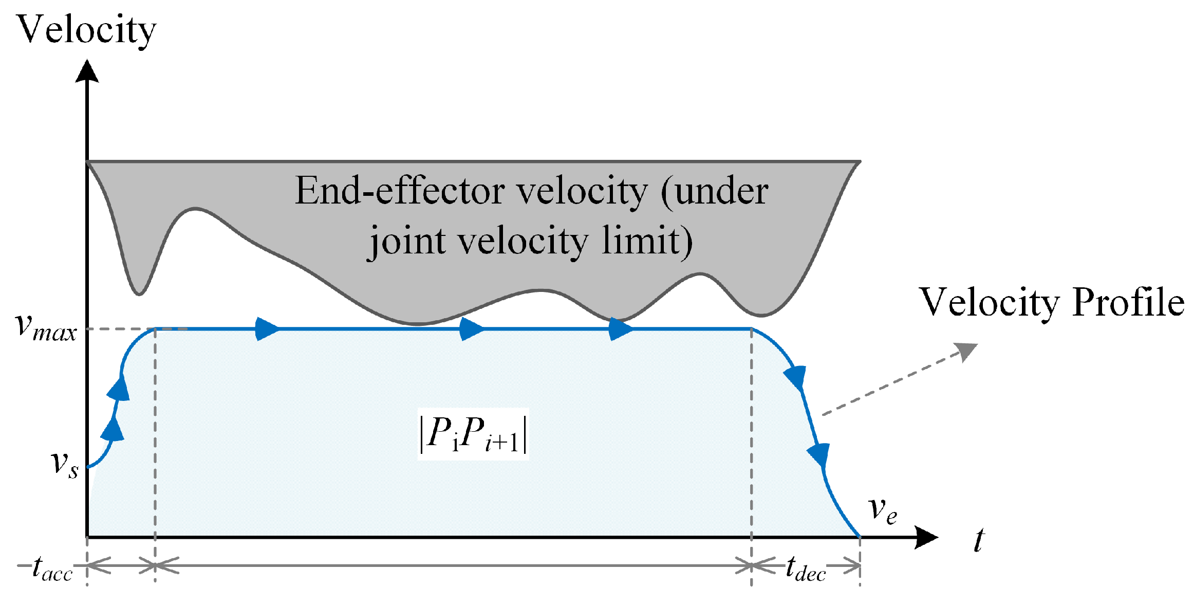
Figure 3 illustrates how joint angular velocity limitations directly restrict the maximum achievable end-effector velocity, thereby demonstrating the impact of joint constraints on the operational performance and feasible workspace of the robotic welding system.
Moreover, constraints on end-effector acceleration (
) and jerk (
) must also be taken into account, as they significantly affect the smoothness of robotic motion and the degree of mechanical wear. The end-effector acceleration can be derived from the Jacobian matrix and its time derivative:
Accordingly, the maximum permissible end-effector acceleration
at each discrete trajectory position is determined by:
Acceleration (
) and deceleration (
) durations for each trajectory segment primarily depend on the required velocity changes and the allowable acceleration and jerk constraints. For simplicity and practical engineering purposes, these durations can be initially approximated using the maximum acceleration constraints:
where
and
represent the initial and final velocities, respectively, and
is the maximum permissible jerk based on the robot’s dynamic constraints.
When the total trajectory segment length (
L) is sufficiently long, the robot can sustain its maximum permissible velocity (
) for a certain duration. The duration of this constant-speed phase (
) is calculated as:
where
and
represent the distances covered during the acceleration and deceleration phases, respectively.
Under jerk constraints, these distances can be accurately calculated by considering higher-order derivative limits of the trajectory:
For shorter trajectory segments, where the total segment length prevents the robot from reaching the theoretical maximum velocity (
), an adjusted maximum velocity (
) must be iteratively determined. A numerical method is used to find
such that the sum of the acceleration and deceleration distances precisely equals the segment length:
Once the revised maximum velocity
is identified, the minimal total travel time
for the segment is calculated as the sum of the acceleration, constant speed (if applicable), and deceleration durations:
Through such optimized trajectory planning, the integration of intelligent path-planning methods with dynamically adaptive motion control strategies significantly enhances robotic tack welding performance and operational flexibility, thereby providing robust and efficient solutions for practical industrial applications.
4. Experimental Platform and Validation
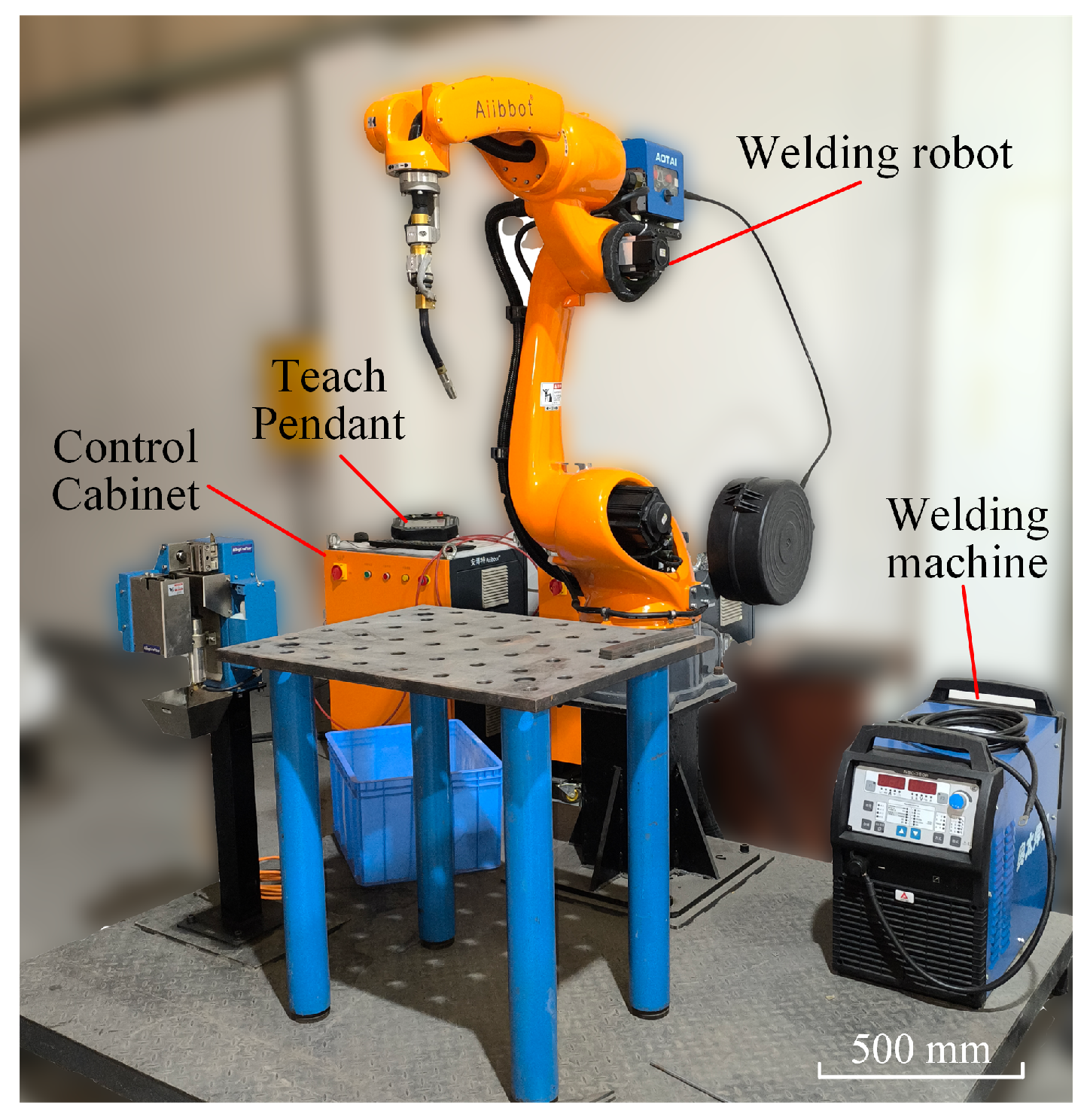
The experimental platform, illustrated in
Figure 4, primarily consists of a six-degrees-of-freedom industrial welding robot and a customized dual-core robot control system. The robot has a maximum working radius of 1465 mm and repeatability positioning accuracy of ±0.08 mm. The control system integrates an RTX64 real-time subsystem with a Windows 10 environment, in which three CPU cores handle Windows-based modules, such as the human–machine interface and data preprocessing, and one dedicated core manages real-time motion control. Communication between the motion controller and servo drives is implemented via an EtherCAT industrial bus operating at a 2 ms cycle time, ensuring the low latency and high-speed data transmission necessary for precise robotic trajectory execution. It is worth noting that the robot controller used in this study is self-developed, enabling flexible integration and full access to trajectory-level and servo-level control modules.
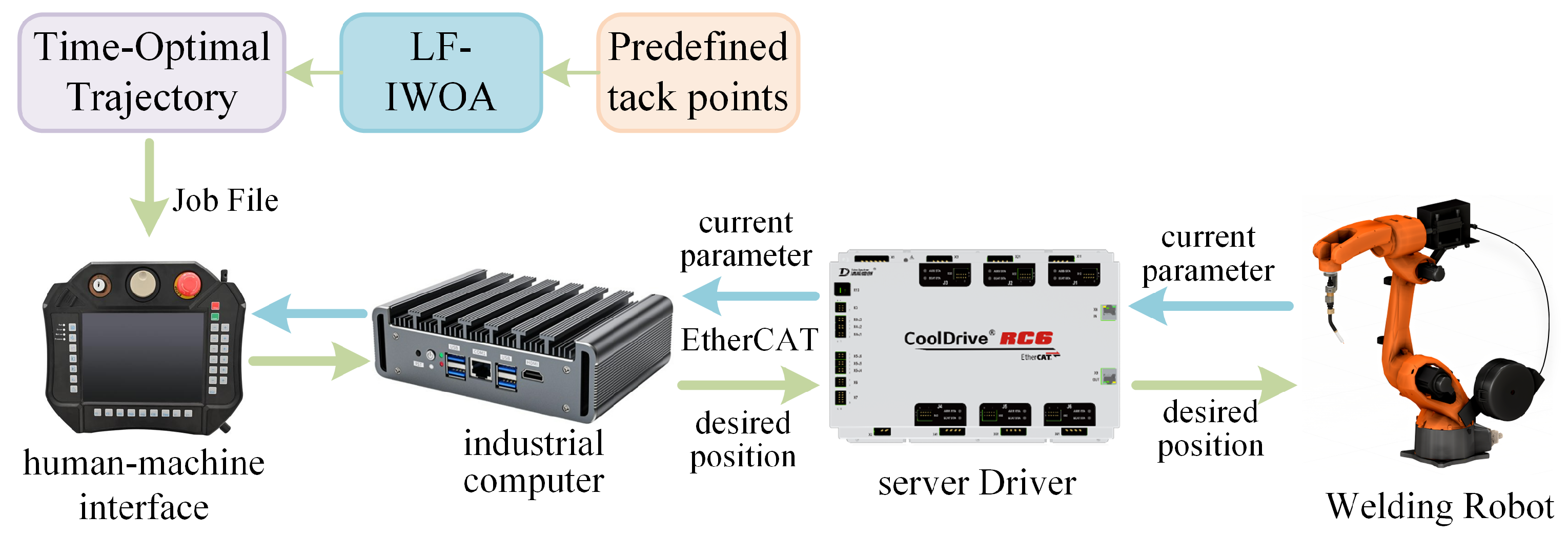
Figure 5 illustrates the overall system workflow. Initially, a predefined set of tack welding points specifies the desired welding positions. The LF-IWOA algorithm is applied to determine the optimal visiting sequence to minimize the total welding path length. Subsequently, a time-optimal trajectory is generated by assigning appropriate velocity and acceleration profiles for each segment. The resulting trajectory is compiled into a robot-controller-compatible format and transmitted through the EtherCAT bus. After the trajectory and motion parameters are determined, the system is capable of automatically generating structured teaching files in TXT format, which comply with predefined syntax rules and can be directly interpreted by the robot controller to execute motion commands. The robot then executes the welding tasks according to the generated trajectory, and real-time motion data are collected during this process.
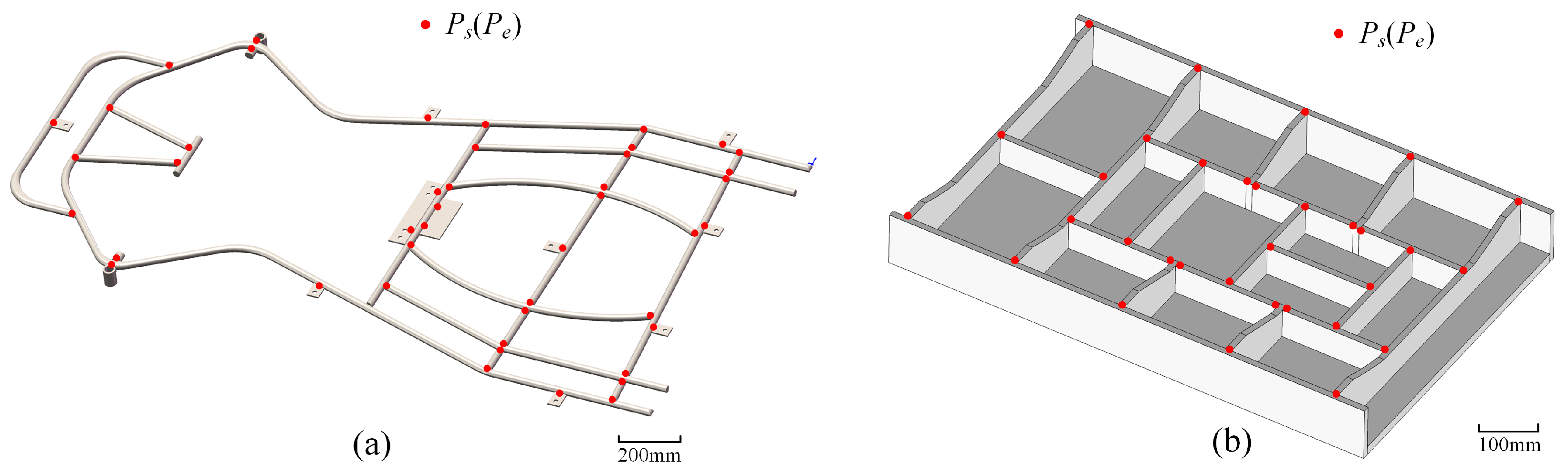
The experiment aimed to evaluate the effectiveness of the proposed LF-IWOA-based trajectory optimization method in reducing welding path length and cycle time. To comprehensively assess the versatility and robustness of the algorithm, two representative workpieces were selected, as shown in
Figure 6. Workpiece 1 (
Figure 6a) is a go-kart chassis frame containing 45 tack welding points arranged densely and irregularly. It represents an unconstrained path planning scenario, requiring the algorithm to determine both the optimal visiting order and the corresponding trajectory. Workpiece 2 (
Figure 6b) is a steel structural frame consisting of 32 tack welding points arranged more regularly and sparsely. Similar to Workpiece 1, no predefined welding path was provided. This ensures consistent experimental conditions for all algorithms under comparison. The difference in structural complexity and point distribution between the two workpieces enables a realistic and diverse evaluation of algorithm performance across varying task difficulties.
To ensure safe and predictable motion during trajectory execution, all inter-point transitions were performed using linear movement mode rather than point-to-point (PTP) movement. This approach guarantees straight-line motion in a Cartesian space, reducing the risk of uncontrolled end-effector paths and potential collisions.
The LF-IWOA algorithm parameters were set based on a combination of literature guidelines and preliminary sensitivity experiments to ensure robust performance. Specifically, population size was set to and maximum iterations to , balancing search capability and computational efficiency. The Lévy flight probability (), elite learning rate (), differential evolution factor (), and crossover rate () were selected from commonly used ranges in related studies and further validated through tuning to achieve stable convergence behavior across different workpiece conditions. Optimization results were benchmarked against several widely-used metaheuristic algorithms, including Genetic Algorithm (GA), standard WOA, Wild Horse Optimizer (WHO), Improved Grey Wolf Optimizer (IGWO), and Coot Optimization Algorithm (COA).
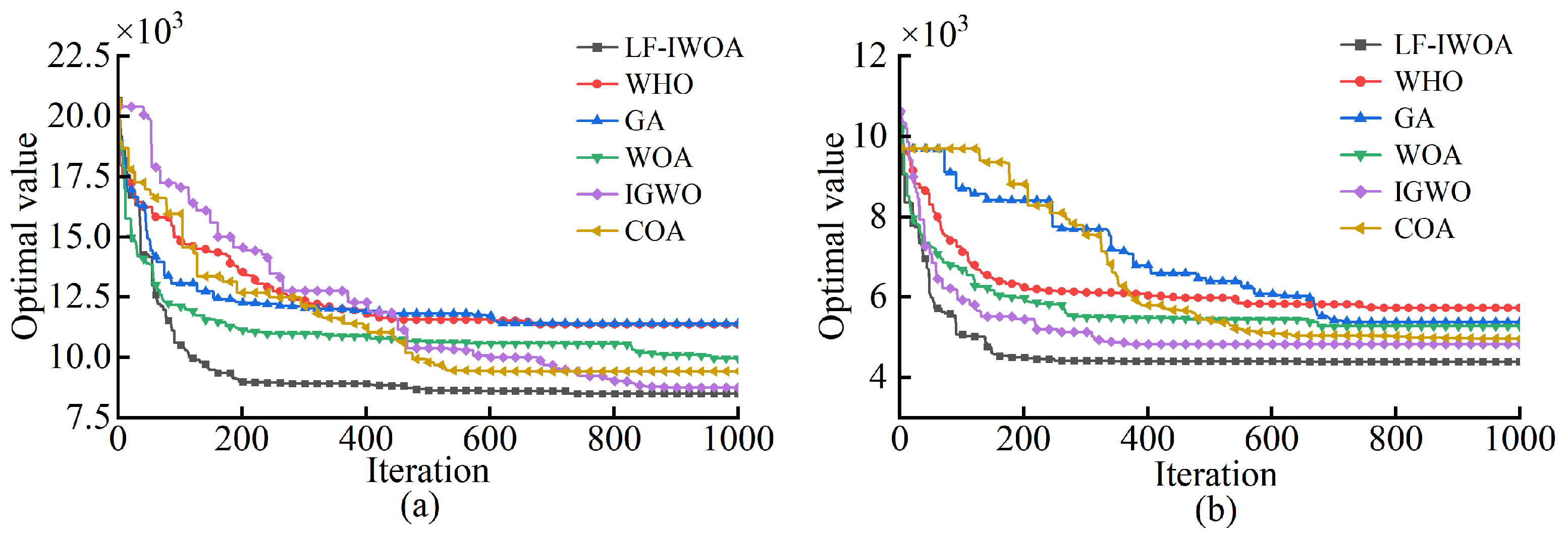
The experimental results in
Figure 7 and
Table 1 demonstrate that LF-IWOA consistently outperformed other tested algorithms in terms of optimization effectiveness and convergence accuracy. For Workpiece 1, LF-IWOA achieved the shortest path length, reducing path length by 2.90% to 25.58% compared with other algorithms. For Workpiece 2, similar improvements were observed, with LF-IWOA outperforming the others by margins ranging from 9.00% to 23.38%. The optimization was initiated from randomly generated solutions, highlighting LF-IWOA’s robust global search capabilities and consistent avoidance of local optima. In addition to path length, computational efficiency was also considered. LF-IWOA required 37.54 s for Workpiece 1 and 26.81 s for Workpiece 2. Although some algorithms such as WHO and GA ran faster, their optimization performance was clearly inferior. This confirms that LF-IWOA achieves a good balance between solution quality and computational cost. These findings also demonstrate the algorithm’s robustness across different workpiece configurations and its practical potential for real-world robotic welding applications.
In conclusion, LF-IWOA’s hybrid structure and enhanced balance of exploration-exploitation make it highly effective for complex path planning tasks.
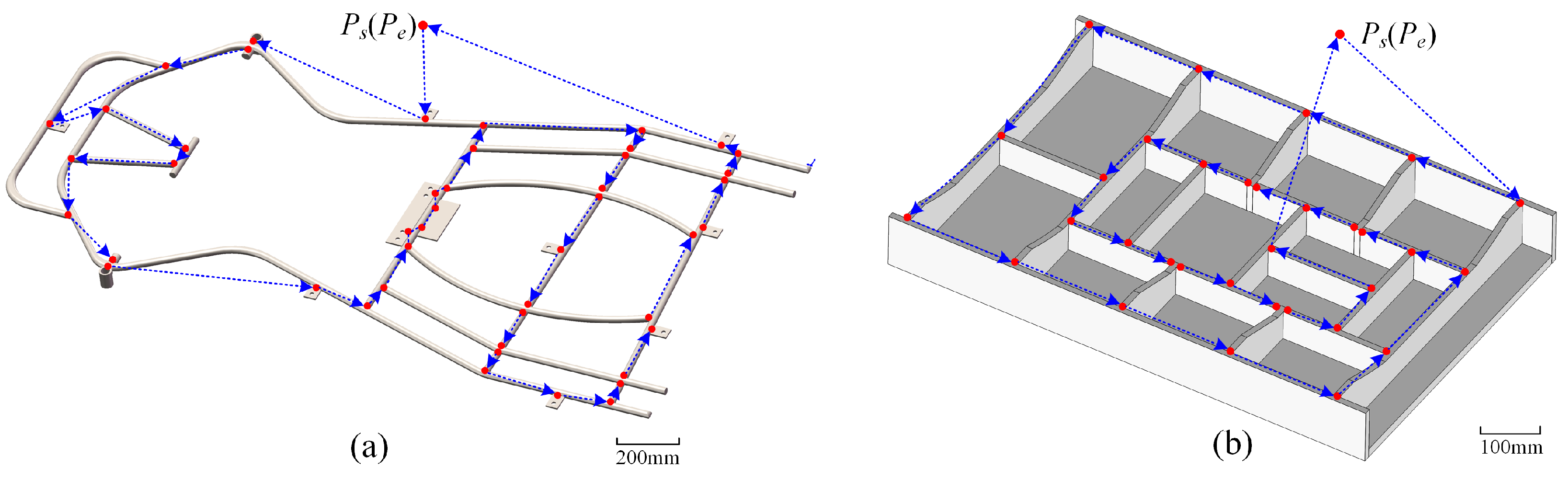
Figure 8 illustrates the final optimized tack welding paths for both workpieces.
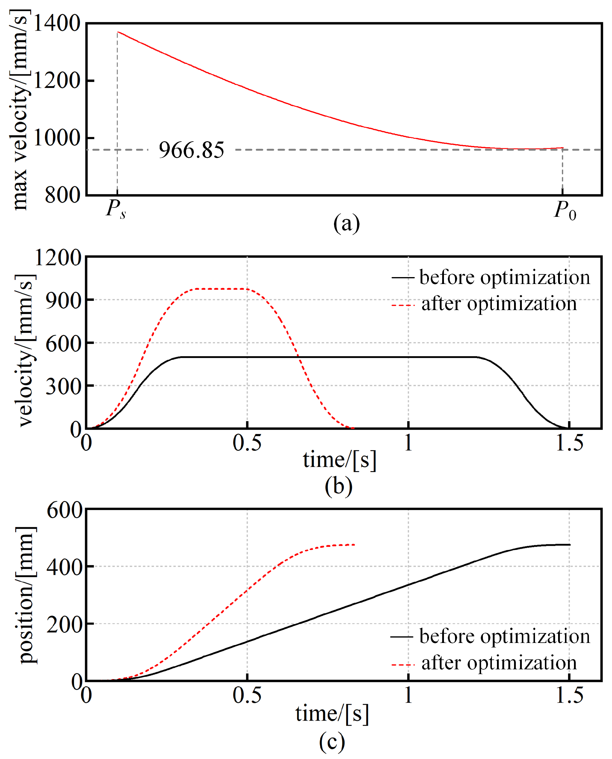
Based on the optimized tack welding path, further improvements in motion execution were implemented through simulation by optimizing the maximum velocity and acceleration time for each path segment to improve overall robotic efficiency. One segment from Workpiece 2 was selected as an example, representing the path from
to
. The robot posture was configured as
. This orientation was uniformly applied to all welding points and remained fixed throughout both the optimization and execution phases. It was selected to ensure tool accessibility and to simplify trajectory planning by avoiding orientation reconfiguration. Interpolation, inverse kinematics calculation, Jacobian matrix evaluation, and end-effector velocity limit computation were performed. The maximum allowable velocity for this segment was determined to be 966.85 mm/s, as shown in
Figure 9a. According to Equation (
13), the corresponding acceleration and jerk constraints were calculated as 5685.61 mm/s
2 and 32,789.56 mm/s
3, respectively. The initial velocity was set to 0 mm/s. Using Equations (
14)–(
20), the acceleration time (
), deceleration time (
), and constant velocity duration (
) were calculated as 0.3431 s, 0.3431 s, and 0.1451 s, respectively. The total simulated motion time was 0.830 s.
Figure 9b,c present the velocity and position profiles before and after optimization. In the baseline simulation, the initial maximum velocity was 500 mm/s, and both acceleration and deceleration times were set to 0.3 s, resulting in a total motion time of 1.502 s. After optimization, the motion time was reduced by 44.74%.
To verify whether the simulation-based optimizations translate into practical improvements, the optimized trajectory was validated on the actual robot platform, taking into account the workspace constraints of Workpiece 2. A dwell time of 5 s per tack welding point was set, with an initial trajectory velocity of 500 mm/s and acceleration time of 0.3 s. These optimized velocity and acceleration profiles were then generated by the algorithm and applied to the robot via teaching files. The teaching files generated from the optimized paths were uploaded to the robot’s controller, and the planned trajectories were executed in real time within the physical workspace. During the physical execution, joint angles, angular velocities, and torques were recorded via the robot’s onboard sensors. This ensures that the evaluation reflects the real behavior of the system under practical operating conditions.
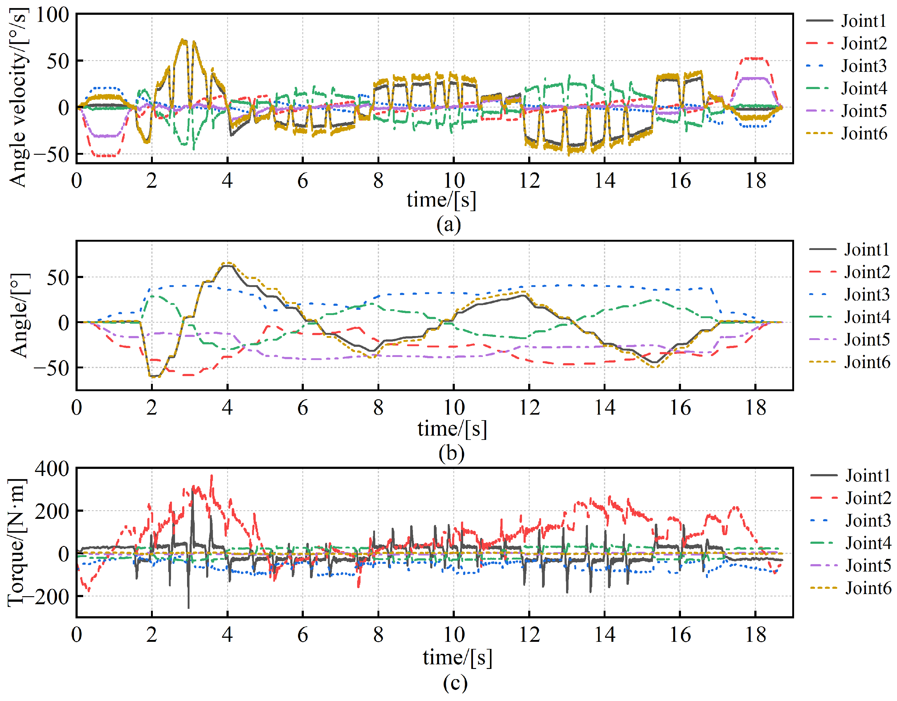
Figure 10 shows the measured data of the robot prior to optimization, providing a baseline for comparison with the optimized results.
In the physical experiment, a constant dwell time of 5 s was assigned to each tack welding point to simulate the actual welding process. Under this condition, the total operation time was reduced from 178.71 s to 173.69 s after applying the optimized trajectory, corresponding to a 2.81% improvement. When the dwell durations were excluded and only the robot’s motion time was considered, the execution time decreased from 18.71 s to 13.69 s. This represents a 26.83% reduction, demonstrating the significant impact of trajectory optimization on motion efficiency.
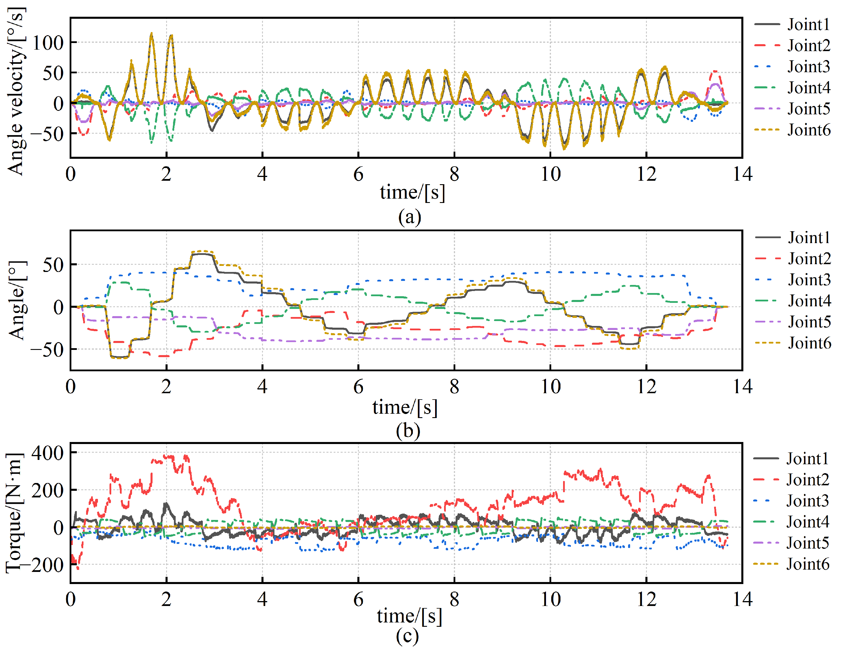
Figure 11a,b present the joint angular velocities and joint angles during optimized robot motions (excluding dwell phases), indicating smooth changes without exceeding predefined operational limits, thereby ensuring welding accuracy and stability. The mechanical energy consumption during robot motion was calculated by multiplying the joint torques (
Figure 11c) by the joint angular velocities (
Figure 11a). The measured energy consumption during physical execution was reduced from 709.26 J to 600.04 J after optimization, achieving an improvement in energy efficiency of 15.40%. These results collectively confirm that the trajectory optimization method not only improves efficiency in simulation but also yields measurable performance gains in real-world robotic operations.
5. Conclusions
To overcome common challenges, such as local optimum entrapment and poor convergence in complex path-planning scenarios, an LF-IWOA was developed, incorporating strategies to significantly enhance global search capability and maintain population diversity. Experimental validation was performed using two industrial workpieces with distinct welding configurations. For the go-kart chassis frame, comprising 45 welding points without a predefined welding sequence, LF-IWOA achieved a total path length of 8498.50 mm, reducing lengths by 34.60% and 21.63% compared to the Genetic Algorithm and the standard Whale Optimization Algorithm, respectively. For the steel structural frame with 32 welding points and a predefined initial sequence, LF-IWOA reduced the path length from 4847.80 mm to 4393.70 mm, achieving a 9.37% improvement over the baseline approach. Comparative experiments further confirmed that LF-IWOA consistently outperformed mainstream metaheuristic algorithms, such as the WHO, IGWO, and COA.
In addition to spatial path planning, a dynamic trajectory model incorporating joint-level constraints such as velocity, acceleration, and jerk limits was developed. A bisection-based velocity adjustment method facilitated time-optimal trajectory execution. When applied to Workpiece 2, this strategy resulted in a 2.81% reduction in total cycle time, a 26.83% decrease in motion duration (excluding dwell time), and a 15.40% reduction in energy consumption, while maintaining smooth and precise joint motions. Although the current method does not reduce robot programming time directly, it enables the automatic generation of globally optimized paths and segment-wise motion parameters, which are difficult to obtain through manual programming. This improves execution quality and provides a foundation for future integration with offline programming systems. Compared with other tested algorithms, LF-IWOA achieved shorter welding paths, better convergence, and more stable results under the same initial conditions. These improvements directly reflect its effectiveness for the specific path and trajectory optimization tasks addressed in this study.
Although LF-IWOA demonstrated superior performance in various welding scenarios, its effectiveness may be limited in highly dynamic environments or when faced with dense and irregular welding point distributions. The workpieces used in this study, though relatively regular, reflect realistic engineering conditions with meaningful spatial and motion constraints. To further assess robustness, future work will consider more irregular or randomized welding layouts. While reinforcement learning (RL) methods offer advantages in dynamic environments, they were not applied in this study due to the static and offline nature of the welding task. Future work will explore RL-based strategies to improve adaptability in more complex scenarios. Future improvements may also involve adaptive parameter tuning and hybrid optimization strategies to enhance performance in more complex scenarios.


