Abstract
The increasing utilization of upper limb rehabilitation robots in rehabilitation therapy has brought to light significant safety concerns regarding their mechanical structures and control systems. This study focuses on a six degrees of freedom (DOF) upper limb rehabilitation robot, which has been designed with an emphasis on safety through careful consideration of its mechanical structure and trajectory planning. Various parameter schemes for the shoulder joint angles were proposed, and the robotic arm’s structure was developed by analyzing the spatial motion trajectories of the shoulder joint motor. This design successfully achieves the objective of minimizing the installation space while maximizing the range of motion. Additionally, an enhanced artificial field method is introduced to facilitate the planning of self-collision avoidance trajectories for dual-arm movements. This approach effectively mitigates the risk of collisions between the robotic arm and the human body, as well as between the two robotic arms, during movement. The efficacy of this method has been validated through experimental testing.
1. Introduction
As of the present date, the global population of stroke patients aged 40 and older has reached approximately 170.4 million [1], with an estimated mortality rate of 1.96 million individuals [2]. Among the survivors, approximately 75% have experienced disabilities [3,4] and a significant loss of physical mobility [5]. Concurrently, the annual incidence of new cases of traumatic spinal cord injury ranges from 100,000 to 140,000, contributing to a cumulative total of over 2 million affected individuals [6,7]. Consequently, the implementation of rehabilitation robots is essential for enhancing the therapeutic outcomes for patients undergoing rehabilitation [8].
Currently, researchers both domestically and internationally have developed over 100 types of upper limb rehabilitation robots, highlighting the growing significance of the safety design in terms of rehabilitation robot systems. The Fraunhofer Institute in Germany has created STRING-MAN, a rope-driven parallel rehabilitation robot that utilizes seven ropes to control the patient’s torso, while additional ropes are employed to measure the torso motion [9]. Meanwhile, the University of Texas has developed the Harmony upper limb rehabilitation robot, which incorporates the glenohumeral joint rhythm phenomenon characteristic of the human shoulder joint. This robot features a shoulder with five degrees of freedom (DOF), enabling simultaneous training of both arms, enhancing limb coordination in hemiplegic patients, and preventing collisions between the robot and the human body through a parallel four-sided mechanism [10]. Zhao Xiaofeng from the Huazhong University of Science and Technology has introduced a two-arm robotic system that utilizes nonlinear model predictive cooperative control. This system is capable of executing various training modalities, including tracking, impedance, force control, and motion synchronization, by modifying the cooperative index. While it demonstrates versatility for a range of complex operational tasks, it is important to note that the rehabilitation training process is intricate and does not adequately address the safety considerations associated with the two-arm robotic system [11]. Chen Li introduced a two-arm participation–man–machine collaboration approach aimed at enhancing upper limb rehabilitation exercises for individuals with hemiplegia. This method integrates the healthy and affected limbs with a robotic system, employing a tailored control strategy to facilitate the patient’s specific movement capabilities. This integration not only enhances patient engagement during rehabilitation but also improves the precision of the movement estimation for the healthy limb, thereby optimizing the trajectory of the rehabilitation exercises. However, challenges may arise due to the substantial size of the robotic structure, which could lead to potential collisions between the robotic arms and between the arms and the patient [12]. Nanjing University of Science and Technology has engineered a 14-degree-of-freedom (DOF) double-arm exoskeleton rehabilitation robot. This design incorporates an angle for shoulder joint abduction/adduction, positioning the abduction/adduction freedom axis at an elevation of 30 degrees. This configuration aims to mitigate the mechanical complications arising from coplanarity between the shoulder joint and the forearm and wrist joints. Nonetheless, a notable limitation of this design is the restricted operational workspace of the manipulator, indicating a need for enhanced flexibility [13,14]. Diao Hui enhanced the artificial potential field method for coordinating two-arm robots, successfully achieving collision-free trajectory planning for both arms by determining the minimum distance between various components of the robot and employing a behavior-based control framework. It is suggested that the process of calculating obstacle avoidance path planning for dual-arm systems in the context of collision detection is complex and that existing collision detection algorithms are inadequate [15]. Liu Zhihui et al. from Donghua University studied the exoskeleton upper limb rehabilitation robot from the perspective of human factors engineering. Mechanical locking devices were added at each joint to limit the rotation angle within the joint limit range, and emergency switches were installed [16]. Wang Xiao et al. proposed a collision response method based on admittance control, which has good applicability for physical collisions between the end of a robotic arm and the operator [17].
However, the above research has the following shortcomings: (1) lack of in-depth research on protection strategies, resulting in secondary harm to patients; (2) rehabilitation training is cumbersome, large in volume, or comes at the expense of working space to achieve the goal of a small mechanical structure, and the applicable population is limited; and (3) the collision corresponding strategy is single, which cannot fully guarantee the man–machine safety. In this paper, a two-arm upper limb rehabilitation robot has been developed. The protection strategy in the process of human–computer interaction is deeply studied. The mechanical mechanism that satisfies the “small installation space-large activity space” is designed, and the two-arm collision avoidance trajectory is planned in real time. The feasibility and safety verification are carried out through simulation and experiment, so as to be better applied to the field of rehabilitation medicine.
2. Design of Upper Limb Rehabilitation Robot
The dysfunction impairment patients targeted by upper limb rehabilitation robots mainly come from the elderly, stroke, shoulder periarthritis, and other populations [18,19,20]. According to the range of motion of male joints aged 18–60, the range of motion of human joints, muscle strength, motor coordination and other activity indicators are taken into account. The joint range of motion indicators pertinent to the design of an upper limb rehabilitation robot, as derived from the combined data of males and females aged 18 to 60, are presented in Table 1. The comprehensive structural design of the rehabilitation robot intended for both arms/upper limbs is illustrated in Figure 1. In this design, the shoulder joint is characterized by three degrees of freedom, the elbow joint by one degree of freedom, and the wrist joint by two degrees of freedom. This configuration facilitates a range of movements, including shoulder joint flexion and extension, adduction and abduction, internal and external rotation, elbow joint flexion and extension, pronation and supination, as well as wrist palmar flexion and dorsiflexion.

Table 1.
The index parameters of each joint of the upper limb rehabilitation robot.
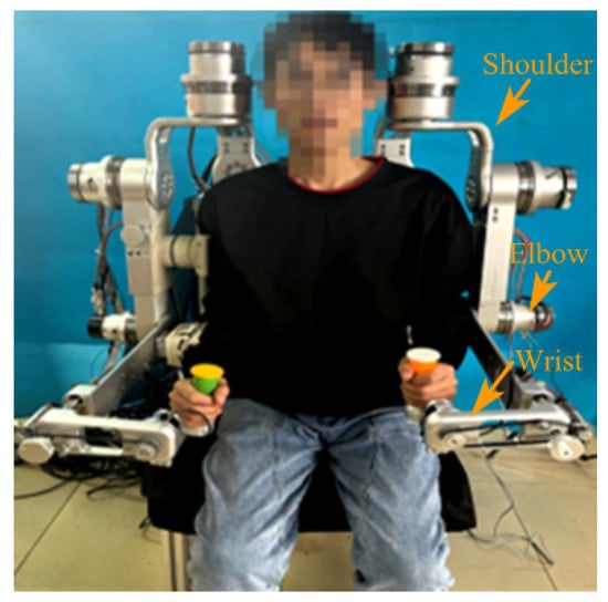
Figure 1.
Upper limb rehabilitation robot.
The joint drive module of the rehabilitation robot is mainly composed of MAXON’s EC-flat motor and Laifu integrated harmonic reducer, as shown in Figure 2, The torque exhibited by each joint varies. The design of the entire series of robotic arms is informed by the performance parameters of each joint, thereby enhancing the overall stability and applicability of the robotic arm as a whole. To ensure that the mechanical arm does not produce any movement after power failure or emergency stop, the drive module is equipped with a BXR LE non-excitation brake between the motor and the reducer to protect the safety of the trainer. When the power is accidentally lost, the non-excitation brake will lock the reducer sleeve in time to prevent the drive module from continuing to output power, ensuring the safety and reliability of the training process. Given the unique characteristics of the range of motion and dimensions of human joints, as well as the diverse contexts and user requirements in human–computer interaction, it is posited that a mismatch between the range of motion of a robotic arm joint and the corresponding parameters of the patient may lead to diminished comfort during use. In more severe instances, such discrepancies could potentially result in secondary injuries. Therefore, the mechanical limit is designed on the joint drive module, and by processing the limited groove on the output rotating bracket, the movement of the limit block installed on the fixed bracket of the drive module is limited, so as to limit the range of motion of the joint of the robotic arm. Moreover, the rehabilitation robot is extensively utilized in the realm of human–computer interaction to enhance safety, diversity, and user comfort.

Figure 2.
(a) Joint drive module. (b) Upper limb rehabilitation machine position control block diagram.
The existing upper limb rehabilitation robot has a large configuration, and it cannot be developed into a wearable robot from the perspective of kinetic energy and energy consumption [21,22,23]. The greatest difficulty in terms of the mechanical layout is the design of the shoulder joint. The shoulder joint is a composite joint, which is the most frequently used, most active and most diverse joint of the human body [24]. The activity space of the upper limb of the human body largely depends on the range of motion of the shoulder joint. However, the shoulder joint space of the human body is small, and the small volume of the shoulder joint activity structure makes it easy to collide with the human body, especially the head [25]. Based on this pain point problem, this paper establishes the human upper limb shoulder joint skeletal model as shown in Figure 3, and the relative position of the 3 DOF shoulder joint of the rehabilitation robot and the human body in the process of motion is analyzed. When the human arm is naturally drooping, the angle between the shoulder joint motor and is , the angle between and is , and the angle between and is .
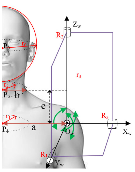
Figure 3.
Upper limb shoulder joint bone model.
According to the human body size of Chinese adults in GB 1000-88 [26], the median body size for males aged 18 to 60 years is utilized, where the height is 223 mm, and the shoulder width is 380 mm, it can be seen that the human body center to point is a = 190 mm, the neck width is b = 50 mm, and the height is c = 60 mm. The equivalent mechanism model of the human shoulder joint with three degrees of freedom is analyzed, as shown in Figure 3. The axes of the three shoulder joint motors are orthogonal to one point. At this point we set up a fixed coordinate system , setting the parameters as follows: face coordinate is , radius of the human head ball is , center of the lower neck is , radius is , center of the upper neck is , radius is , is the distance between the shoulder joint and the axis intersection is ; and the data are shown in Table 2.

Table 2.
Parameter list.
Based on the safety consideration of engineering practice [27], it can be seen that in the process of movement, the relative position of the motor and human body is fixed, and there is no collision between and the human head. When the motor runs, it drives to perform spatial motion. At this time, may collide with the human head. During rehabilitation exercise, the shoulder joint motor is always located on the outer side of the human arm, making it less likely to collide with the human head. To prevent collisions between the shoulder joint motor and the human body, the angle , and of the three motors can be changed. The shoulder joint motor does not affect the motion space of , so coincides with the axis of the world coordinate system . The shoulder joint motor is the first motor of the base, and the power is large; when the installation angle is 90°, the power is minimal. Therefore, this paper only considers the installation angle between the shoulder joint motor and the other motors. Based on engineering considerations, the angle parameters are set as 90°, 60° and 45°, respectively. Combined with the numerical calculation and analysis, the human head is assumed to be a sphere, and the equation for the sphere is as follows:
In order to easily understand and calculate, the motor can be seen as a sphere rotating around the intersection point of the shoulder joint axis, and the sphere equation is as follows:
When the shoulder joint motor is moving, the is driven to space motion and the path of the motion is a plane perpendicular to the . The space plane path equation is , so the space plane path equation and the sphere of the motor motion is obtained, and the section is a circle, which can determine whether the shoulder joint collides with the human head. The result is shown in Figure 4.
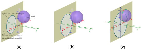
Figure 4.
Schematic diagram of the head collision between the mechanism and the human. (a) , , where there will be no collision. (b) , , where there will be no collision. (c) , where there is a collision.
It can be seen from the figure that when , will collide with the human head. When , and , there will be no collision. Then, further research will be conducted on the workspace of the shoulder joint, through the MATLAB Robot Toolbox simulation analysis, when , , , and , for the comparison between the three degrees of freedom range of motion of the shoulder joint and the range of motion of the rehabilitation robot’s shoulder joint that is obtained, as shown in Table 3.

Table 3.
Range of motion table of the shoulder joint.
By comparing the range of motion of the shoulder joint and the motion space of the manipulator in these two cases, it shows that when the shoulder joint motor , , the motion space of the robot arm is larger and there is no collision with the human head during movement.
3. Analysis of Safe Distance between Mechanical Arm and Human Body
When the upper limb rehabilitation robot drives the human body for rehabilitation training, the mechanical arm may collide with the human body, and the upper limbs of the human body driven by the two arms may also collide with each other. Therefore, safety design is necessary for the trajectory planning of the manipulator. The distance between the robotic arm and the human body or another robotic arm, also known as the safety distance, is the most important motion parameter. Once the safety distance exceeds the set threshold, the warning mechanism and the emergency stop mechanism will be triggered.
In order to conveniently judge whether the spatial distance between each joint or connecting rod of the robotic arm and the sitting–standing human body, and whether the spatial distance between the two robotic arms meets the requirements of the safe area, the bounding box envelope method is used to simplify the mechanism model of the upper limb rehabilitation robot [28,29]. By employing an optimization approach for the parameters of the mechanism, it is possible to prevent collisions between the robot’s shoulder joint and the human body. Additionally, the dimensions of the shoulder joints on both arms are minimized, thereby eliminating any potential interference between them. Consequently, the two segments, namely the upper arm section and the forearm section, can be simplified. The upper arm section is defined as the segment extending from the shoulder motor to the elbow joint motor, while the forearm section is characterized as the segment between the elbow joint and the wrist joint motor. For the purpose of simplification, a “capsule body” bounding box is utilized, as illustrated in Figure 5 and Figure 6.
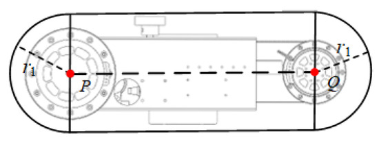
Figure 5.
Big arm capsule body bounding box.

Figure 6.
Forearm capsule body bounding box.
In the figure, the two ends of the capsule body in the upper arm section are point P and point Q, respectively, where point P is the location point of the shoulder motor 3 and point Q is the location point of the elbow motor. The two ends of the capsule body in the forearm section are point Q and point W, respectively, where point Q is the location point of the elbow motor and point W is the location point of the wrist motor. The capsule body bounding box is bound with the upper arm section and the forearm section, and it moves with the manipulator. There is a certain size of excess space in the bounding box, which provides secondary protection for the human arms and robotic arms, improving the system safety.
The collision detection of the upper limb rehabilitation robot mainly detects whether the minimum distance between the robot arm and the patient is less than the set safe distance when the patient performs rehabilitation training to determine whether there is a collision. That is:
In the formula: —the minimum safe distance between the two enclosing boxes; and —the minimum distance between two bounding boxes.
In this paper, the collision detection of the sphere bounding box and capsule bounding box is needed. Before calculating the minimum distance, the secondary projection method is used to detect the collision of the bounding box preliminarily, so as to reduce unnecessary complex operations, such as square root and multiplication, and improve the efficiency of the collision detection. As shown in Figure 7, taking the sphere bounding box as an example, the two bounding boxes are projected onto three coordinate planes, respectively, and the collision is judged according to the intersection of the two bounding boxes on the three projection planes. If the two bounding boxes do not intersect on every projection plane, it is proved that there is no collision between the two bounding boxes. On the contrary, it is necessary to further judge the collision situation of the group of bounding boxes by calculating the minimum distance.
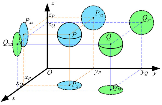
Figure 7.
Secondary projection diagram of the space bounding box.
3.1. Analysis of Safe Distance between Mechanical Arm and Human Body in Standing Position
It is necessary to determine whether the spatial distance between the joints and connecting rods of the robot arm and the human body in the standing position meets the requirements of the safe area. According to the size of patients with different heights and weights, corresponding safety distances need to be set. This article takes the example of a cylinder with an equivalent length of 500 mm for the human torso and two cylinders with a diameter of 200 mm that simplify the legs to be fixed and tangent to the upper body cylinder. At the same time, it is assumed that the robot arm of the upper limb rehabilitation robot is a cylinder and the joint is a sphere.
The fixed coordinate system of the human body is set up, where is the position of the center of mass of the human body, and the center of mass of the ith joint of the upper limb of the human body is . Because the robot arm is attached to the lateral side of the upper limb of the human body, the corresponding i the joint after offset is . Suppose is the position of a point N on the -link of the robot arm, then it can be known.
The distance between the projection position and point in the plane is obtained by projecting the M, N and O points to the plane:
The distance from each joint of the robot arm to the human body in a standing position can be known, and the distance to the fixed cylinder is as follows:
In order to avoid a collision between the robot arm and the patient, the two-point distance and of the rehabilitation robot arm in the rehabilitation training should always be greater than the corresponding connecting rod radius and joint radius. As shown in Figure 8, the minimum value of the distance between each link of the robot arm and the distance between the connecting rod and the sitting human body after projection in the plane is :
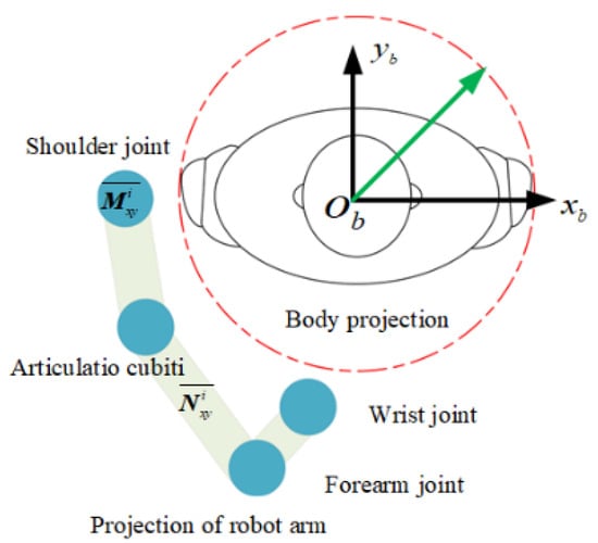
Figure 8.
Analysis of the safe distance between the mechanical arm and the human body in a sitting position.
3.2. Analysis of Safe Distance between Mechanical Arm and Human Body in Sitting Position
The upper limb rehabilitation robot designed in this paper can be trained in standing and sitting postures. Since the shape of the human body will change in the sitting posture, which further reduces the safe movement range of the upper limb rehabilitation robot arm, the above-mentioned safe distance calculation method for preventing a collision is no longer applicable to the sitting posture training state. In order to determine whether the spatial distance between each joint, as well as the connecting rod of the manipulator and the human body, is in a safe motion area, the upper body in the sitting position is simplified into a fixed cylinder with a diameter of 500 mm, and the legs are simplified into two fixed cylinders with a diameter of 200 mm, which are tangent to the upper body cylinder. At the same time, it is assumed that the manipulator of the upper limb rehabilitation robot is a cylinder and each joint is a sphere.
Suppose that the upper body cylinder of the human body is , the center of mass of the cylinder of the human legs is and , and the gth joint of the human upper limb is in the sitting position. It is assumed that is the position vector of a point on the gth connecting rod of the robot arm.
Points , and , , are projected onto the plane to obtain point , point and point , , in the plane, respectively, so that the spatial distance is simplified into the distance between two points in the plane, and the distance between point and point can be calculated as follows:
It can be seen that the distance from each joint of the robot arm to the upper body cylinder in the sitting position is as follows:
Similarly, the distance from a point on each link of the robot arm to the upper body cylinder in the sitting position is as follows:
Similarly, the distances from each joint of the robot arm to the lower body cylinder in the sitting position of the human body can be obtained as follows:
The distance from the point on each link of the robot arm to the lower body cylinder in the sitting position of the human body is as follows:
In order to avoid a collision between the rehabilitation robot arm and the patient, the distance between the joints and the connecting rod of the rehabilitation robot arm and the human body in the sitting position should be always greater than the corresponding connecting rod radius and joint radius during the rehabilitation training. As shown in Figure 9, the minimum value of the distance between the joints and the connecting rod of the robot arm and the sitting position of the human body after projection in the plane is :
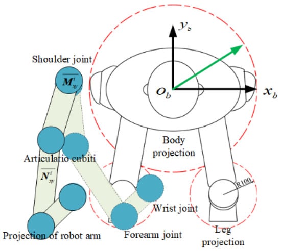
Figure 9.
Analysis of the safe distance between the mechanical arm and the human body in a sitting position.
The safe distance between the robot arm and the human body is detected in real time during operation. Once the set threshold is exceeded, the warning mechanism and further emergency stop mechanism will be triggered.
4. Self-Collision Avoidance Trajectory Planning
4.1. Improved Artificial Potential Field
The upper limb rehabilitation robot designed in this paper is a series linkage mechanism. The movement of the robot arm is coupled, and the movement of any joint will affect the pose of its adjacent joints. In addition, when the rehabilitation robot is in operation, there may be a collision between the robot arm and the patient’s body. If the traditional artificial potential field method is used to plan the collision avoidance path of the dual-arm upper limb rehabilitation robot, the path search space is Cartesian space, meaning each planning step needs to solve the inverse solution of the path point through inverse kinematics and screen out the minimum potential energy joint combination value. This not only greatly increases the computational complexity but may also calculate the singular value, resulting in a sudden change in the joint angle, which is not ideal in the practical application of the robot arm obstacle avoidance planning [30,31,32,33].
Therefore, this paper chooses the joint space as the search space of the collision avoidance path, takes the joint angle as the control variable, searches the adjacent joint combination of the current state through the appropriate step size, and selects a set of joint angle values with the smallest potential energy as the next pose of the robot arm. Compared with the traditional artificial potential field method, the path points obtained by searching in the joint space are reachable, and there is no need for an inverse solution, and there will be no singular points, so that the path is continuous, the calculation process is greatly simplified, and the time required for self-avoidance trajectory planning is reduced.
The gravitational potential field function of the improved robot arm can be calculated according to the angle difference between the current pose of each joint and the target pose:
Among them, is the current angle value of each joint of the robot arm, and is the target angle value of each joint.
Aiming at the problem that the robot arm cannot reach the target point due to the obstacle, the distance between the robotic arm and the target point is introduced as an influencing factor in the traditional repulsion field function, so that the repulsion field is more sensitive to the change of distance. At this time, when the robot arm is close to the target point, the repulsion force gradually becomes larger, but as the distance decreases, it is largely driven by the reaction force to push the robot arm. In addition, the absolute safety distance is introduced. When the distance between the two robot arms is less than or equal to , the repulsive force is set to a maximum value to ensure the absolute safety of the patient.
At this time, the repulsion field function is expressed as follows:
The repulsive force potential field of the robot arm is as follows:
Then, the corresponding repulsion function becomes the following:
In the following formula:
where the potential energy of the robot is as follows:
In the work of the dual-arm upper limb rehabilitation robot system, there may be a local minimum value. Therefore, a virtual obstacle is added to break the force balance and avoid the robotic arm falling into the local minimum value.
4.2. The Specific Process of the Algorithm
In this paper, the master–slave path planning method is used to plan the collision avoidance path of the dual-arm upper limb rehabilitation robot. Before the formal planning, in order to ensure the most effective rehabilitation effect, the left and right robotic arms are set according to the rehabilitation needs. When the patient’s left arm is the affected limb and the right arm is the healthy limb, the left arm is set as the main arm and the right arm is set as the slave arm. On the contrary, the right arm is set as the main arm and the left arm is set as the slave arm. When both arms are affected limbs, it can be selected and set according to the actual rehabilitation needs.
When the collision avoidance path planning is carried out, the path planning of the main arm is first carried out. At this time, the real-time pose of the main arm is known, and then the main arm is regarded as a dynamic obstacle and the collision avoidance path planning of the slave arm is carried out according to the real-time pose of the main arm. The specific algorithm flow is shown in Figure 10.
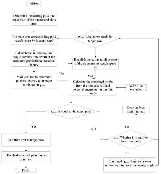
Figure 10.
Algorithm flow chart.
When planning the collision avoidance path, this paper selects the path of the upper limb rehabilitation exercise for the simulation test and verifies the effectiveness of the self-avoidance algorithm by comparing the simulation results’ existence or nonexistence in terms of the self-avoidance algorithm.
4.2.1. Simulation of Non-Self-Avoiding Collision Algorithm
In the experimental simulation of the non-self-avoiding collision algorithm, the left arm is set to move from the left lower initial position = [0° 0° 40° −30° 0° 0° 0°] to the right upper position, and the end position is = [0° −20° 30° −40° 0° 0°]; the right arm moves from the right lower initial position = [0° 0° −60° −45° 0° 0°] to the left upper position, and the end position is = [0° 45° −5° 55° 0° 0°]; and the left and right arms move normally. Assuming that the absolute safe distance is 50 mm, MATLAB is used to simulate the angle changes of each joint of the right arm, as shown in Figure 11a.
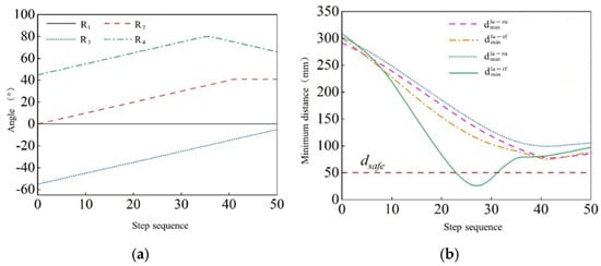
Figure 11.
Non-self-collision avoidance algorithm simulation. (a) From the arm and shoulder, the elbow joint angle changes. (b) The minimum distance between the arms of each bar.
The left forearm and the left upper arm are used to detect the collision of the space bounding box of the right forearm and the right upper arm, respectively, and the minimum distance between the left and right robot arm during the current motion is calculated, where is the minimum distance between the left forearm and the right forearm, is the minimum distance between the left forearm and the right upper arm, is the minimum distance between the left upper arm and the right forearm, and is the minimum distance between the left upper arm and the right upper arm, as shown in Figure 11b.
As shown in Figure 12, the minimum distance between the left forearm and the right forearm is less than the absolute safe distance , and the collision between the two arms is determined. It is proved that in the absence of a self-collision avoidance algorithm, the two arms cannot achieve self-collision avoidance path planning by adjusting the angle.
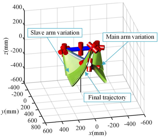
Figure 12.
Two-arm simulation three-dimensional diagram.
4.2.2. Self-Collision Avoidance Algorithm Simulation
In the simulation experiment with the self-collision avoidance algorithm, the left arm is set as the main arm, and its motion path is still moving from the lower left initial pose = [0° −30° 60° −60° 0° 0° 0°] to the upper right, and the end pose is = [0° 0° 40° −30° 0° 0°]; the right arm is the slave arm, which moves from the lower right initial position = [0° −30° 60° −60° 0° 0°] to the upper left, and the end position is = [0° −30° 60° −60° 0° 0°]. The gravitational gain coefficient is 10, the repulsive gain coefficient is 1000, the absolute safe distance is 50 mm, the obstacle repulsive e radius is 60 mm, the main arm (left arm) moves normally, and the right arm avoids a collision by the self-avoidance algorithm. The simulation experiment is carried out by using MATLAB. The simulation results and the changes in the joint angles of the arm (right arm) are as shown in Figure 13a. Similarly, collision detection is performed on the left forearm and the right forearm, the left big arm and the right forearm, the right big arm and the left forearm, and the left big arm and the right big arm. The minimum distance between the rods of the left and right robot arm is shown in Figure 13b.
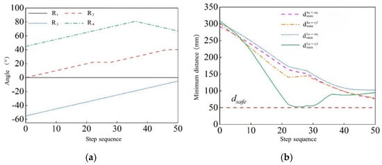
Figure 13.
The self-collision avoidance algorithm simulation. (a) From the arm and shoulder, the elbow joint angle changes. (b) The minimum distance between the arms of each bar.
The simulation of the two arms by MATLAB is shown in Figure 14. After adding the self-collision avoidance algorithm, the secondary robot arm joint angle fluctuates slightly at several points. During the movement of the two arms, the minimum distance between all the rods of the two arms is always greater than the absolute safety distance .There is no collision between the two arms during the movement. It is proved that the self-collision avoidance algorithm of the improved artificial potential field method can realize the self-collision path planning of the two arms by the secondary robot arm joint angle.
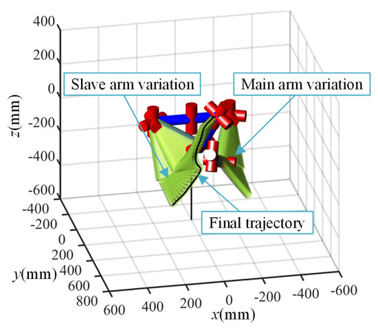
Figure 14.
Two-arm simulation three-dimensional diagram.
5. Experimental Analysis
In order to verify the feasibility of the self-collision avoidance algorithm of the dual-arm upper limb rehabilitation robot, a self-collision avoidance trajectory tracking experiment is carried out on the prototype. The experiment is carried out in a sitting position, and the left arm is set as the main arm to make it forward and fixed. The angle of each joint is = [0° −20° 30° −40° 0° 0°]. The right arm is set as the slave arm, and the self-avoidance movement is performed from the lower right side of the left arm to the upper left side of the left arm. The initial position is = [0° 0° −60° 45° 0° 0°], the end position is = [0° 45° −5° 55° 0° 0°], and the absolute safe distance is 50 mm. The experimental scene is shown in Figure 15. During the experiment, the angle of each joint of the right arm is read by the angle sensor, as shown in Figure 16a, and the minimum distance between the rods of each segment between the two arms is obtained, as shown in Figure 16b.

Figure 15.
Experimental scene diagram of the dual-arm self-collision avoidance.
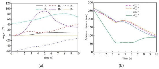
Figure 16.
Double-arm self-collision avoidance experiment. (a) Angle of each joint of the right arm. (b) The minimum distance between the arms of each bar.
Figure 16 shows the angle change of each joint of the right arm in the experiment within 10 s. The change range of each joint angle of the right arm is within the angle range of each joint of the normal human body. For the forearm joint, the angle increases rapidly with the time at 0.8 s, reaches the maximum at 5 s, and then decreases rapidly with the time. At 9 s, it tends to be stable. The speed of the whole process is basically stable. When the joint limit is reached, the speed is 0, the acceleration does not change abruptly, and the movement is relatively stable, which is in line with the normal human body. The minimum distance between the two arms is always greater than the absolute safe distance of 50 mm. Since no collision occurred during the whole experiment, this proves that the dual-arm self-collision avoidance algorithm proposed in this paper has good practicability and reliability while ensuring safety. Therefore, the algorithm can be applied to the trajectory planning of dual-arm upper limb rehabilitation robots in rehabilitation training, helping patients to carry out effective rehabilitation exercises in a safe environment, so as to promote their rehabilitation effect. Although the trajectory planning strategy based on the improved artificial potential field method proposed in this study performs well in simulation and experiment, other advanced trajectory planning algorithms can be explored to further improve the efficiency and safety of the trajectory planning. At the same time, the robot should be applied to the actual clinical environment for large-scale clinical trials to verify its performance and effectiveness in a real environment.
6. Conclusions
This paper presents a novel intelligent rehabilitation robot designed for upper limb therapy. Recognizing the critical importance of safe operation during human–computer interaction, the study focuses on the safety aspects of the robot’s mechanical structure and trajectory planning. An equivalent mechanism data model is established to analyze the spatial relationship between the shoulder joint motor and the relative positioning of the human body across various parameters. This analysis facilitates the selection of a specific set of angular parameters for the shoulder joint motor, enabling the upper limb rehabilitation robot to achieve the objective of “minimal installation space—maximal activity space”.
To mitigate the risk of collisions between the robot arm and the human body, as well as between the robot arms during trajectory movements, a trajectory planning strategy based on an enhanced artificial potential field method is proposed. This strategy aims to enhance the safety of the trajectory planning process for the upper limb rehabilitation robot. Finally, the viability of the proposed trajectory planning strategy is validated through simulations and experimental results, which also demonstrate the safety of the mechanical design of the upper limb rehabilitation robot.
Author Contributions
Software, writing—original draft preparation, writing—review and editing, C.Z.; Conceptualization, H.Y.; Formal analysis, J.W.; Investigation, F.Z. and Z.S.; Validation X.L. All authors have read and agreed to the published version of the manuscript.
Funding
This work was supported by the Hebei Natural Science Foundation under Grant E2022402059, by the Science and Technology Research Project of Hebei Province Higher Education Institutions in under Grant QN2023122, by the Key Technologies Research and Development Programme under Grant SQ2019YFB130349, and in part by the University-Industry Collaborative Education Programme of the Ministry of Education under Grant 22097118175453.
Data Availability Statement
Data are contained within the article.
Conflicts of Interest
Author Jian Wei was employed by Shandong Haomai Machinery Manufacturing Co., Ltd. The funders had no role in the design of the study; in the collection, analyses, or interpretation of data; in the writing of the manuscript; or in the decision to publish the results.
References
- Wang, L.; Peng, B.; Zhang, H. Brief report on stroke prevention and treatment in China 2020. Chin. J. Cerebrovasc. Dis 2022, 20, 136–144. [Google Scholar]
- Wang, Y.; Li, Z.; Gu, H. China Stroke Report 2020 (Chinese Version) (1). Chin. J. Stroke 2022, 17, 433–447. [Google Scholar]
- Qassim, H.M.; Hasan, W.Z. A review on upper limb rehabilitation robots. Appl. Sci. 2022, 10, 6976. [Google Scholar] [CrossRef]
- Anwer, S.; Waris, A.; Gilani, S. Rehabilit-ation of upper limb motor impairment in stroke: A narrative review on the prevalence, risk factors, and economic statistics of stroke and state of the art therapies. Healthcare 2022, 10, 190. [Google Scholar] [CrossRef]
- Proietti, T.; Ambrosini, E.; Pedrocchi, A. Wearable robotics for impaired upper-limb assistance and rehabilitation: State of the art and future perspectives. IEEE Access 2022, 10, 106117–106134. [Google Scholar] [CrossRef]
- Moulaei, K.; Bahaadinbeigy, K.; Haghdoostd, A.A.; Nezhad, M.S.; Sheikhtaheri, A. Overview of the role of robots in upper limb disabilities rehabilitation: A sco** review. Arch. Public Health 2023, 81, 84. [Google Scholar] [CrossRef]
- Cardona, M.; Solanki, V.K.; Cena, C.E.G. Exoskeleton Robots for Rehabilitation and Healthcare Devices. J. Rehabil. Robot. 2020, 1–11. [Google Scholar]
- Borboni, A.; Villafañe, J.H.; Mullè, C.; Valdes, K.; Faglia, R.; Taveggia, G.; Negrini, S. Robot-assisted rehabilitation of hand paralysis after stroke reduces wrist edema and pain: A prospective clinical trial. J. Manip. Physiol. Ther. 2017, 40, 21–30. [Google Scholar] [CrossRef] [PubMed]
- Surdilovic, D.; Zhang, J.; Bernhardt, R. STRING-MAN: Wire-robot technology for safe, flexible and human-friendly gait rehabilitation. In Proceedings of the lnternational Conference on Re-Habilitation Robotics, Noordwijk, The Netherlands, 13–15 June 2007; IEEE: New York, NY, USA, 2007; pp. 446–453. [Google Scholar]
- Kim, B.; Deshpande, A.D. An upper-body rehabilitation exoskeleton Harmony with an anatomical shoulder mechanism: Design, modeling, control, and performance evaluation. Int. J. Robot. Res. 2017, 36, 414–435. [Google Scholar] [CrossRef]
- Zhao, X.; Zhang, Y.; Ding, W.; Tao, B.; Ding, H. A dual-arm robot cooperation framework based on a nonlinear model predictive cooperative control. IEEE/ASME Trans. Mechatron. 2023, 1–13. [Google Scholar] [CrossRef]
- Chen, L.; Qiu, J.; Zou, X.; Cheng, H. A Dual-Arm Participated Human-Robot Collaboration Method for Upper Limb Rehabilitation of Hemiplegic Patients. In Proceedings of the 2023 IEEE International Conference on Robotics and Automation (ICRA), London, UK, 29 May–2 June 2023; pp. 12617–12623. [Google Scholar]
- Xu, H. Research on Structural Design and Control of Seven-Degree of Freedom Exoskeleton Upper limb Rehabilitation Training. Ph.D. Thesis, Nanjing University of Science and Technology, Nanjing, China, 2021; p. 34. (In Chinese). [Google Scholar]
- Legnani, G.; Fassi, I.; Tasora, A.; Fusai, D. A practical algorithm for smooth interpolation between different angular positions. Mech. Mach. Theory 2011, 162, 104341. [Google Scholar] [CrossRef]
- Diao, H.; Chen, G.; Cao, F. Obstacle Avoidance Path Planning of Double Manipulator Based on Collision Detection. Mach. Tool Hydraul. 2024, 52, 43–49. [Google Scholar]
- Liu, Z. Research on the human factors engineering of motor function rehabilitation system for upper limb exoskeleton. Ph.D. Thesis, Donghua University, Shanghai, China, 2017. [Google Scholar]
- Wang, X. Collision Detection and Safe Control of Cooperative Manipulators. Masteral Dissertation, China University of Mining and Technology, Xuzhou, China, 2022. [Google Scholar]
- Rose, C.G.; Deshpande, A.D.; Carducci, J. The road forward for upper-extremity rehabilitation robotics. Curr. Opin. Biomed. 2021, 19, 100291. [Google Scholar] [CrossRef]
- Wu, J.; Cheng, H.; Zhang, J.; Yang, S.; Cai, S. Robot-assisted therapy for upper extremity motor impairment after stroke: A systematic review and meta-analysis. Phys. Ther. 2021, 101, pzab010. [Google Scholar] [CrossRef]
- Taravati, S.; Capaci, K.; Uzumcugil, H.; Tanigor, G. Evaluation of an upper limb robotic rehabilitation program on motor functions, quality of life, cognition, and emotional status in patients with stroke: A randomized controlled study. Neurol. Sci. 2022, 43, 1177–1188. [Google Scholar] [CrossRef]
- Franceschini, M.; Mazzoleni, S.; Goffredo, M.; Pournajaf, S.; Galafate, D.; Criscuolo, S.; Posteraro, F. Upper limb robot-assisted rehabilitation versus physical therapy on subacute stroke patients: A follow-up study. J. Bodyw. Mov. Ther. 2020, 24, 194–198. [Google Scholar] [CrossRef] [PubMed]
- Gu, Q.; Tian, J.; Yang, B.; Liu, M.; Gu, B.; Yin, Z.; Zheng, W. A novel architecture of a six degrees of freedom parallel platform. Electronics 2023, 12, 1774. [Google Scholar] [CrossRef]
- Pang, Z.; Wang, T.; Wang, Z.; Yu, J.; Sun, Z.; Liu, S. Design and analysis of a wearable upper limb rehabilitation robot with characteristics of tension mechanism. Appl. Sci. 2020, 10, 2101. [Google Scholar] [CrossRef]
- Ning, Y.; Wang, H.; Tian, J.; Zhu, P.; Yang, C.; Niu, J. Design, optimization, and analysis of a human-machine compatibility upper extremity exoskeleton rehabilitation robot. Proc. Inst. Mech. Eng. Part C J. Mech. Eng. Sci. 2023, 237, 2802–2814. [Google Scholar] [CrossRef]
- Yan, H. Configuration design of an upper limb rehabilitation robot with a generalized shoulder joint. Appl. Sci. 2021, 11, 2080. [Google Scholar] [CrossRef]
- The State Bureau of Quality and Technical Supervision. Human Dimensions of Chinese Adults; Standards Press of China: Beijing, China, 1989; pp. 1–18.
- Singh, H.; Unger, J.; Zariffa, J.; Pakosh, M.; Jaglal, S.; Craven, B.C.; Musselman, K.E. Robot-assisted upper extremity rehabilitation for cervical spinal cord injuries: A systematic sco** review. Disabil. Rehabil. Assist. Technol. 2024, 13, 704–715. [Google Scholar] [CrossRef] [PubMed]
- Zhang, T.; Zang, X. Distributed model predictive control with particle swarm optimizer for collision-free trajectory tracking of mwmr formation. Actuators 2023, 12, 127. [Google Scholar] [CrossRef]
- Zhao, D.; Wang, X.; Chen, G. Collision Detection Method of Approximate Convex Hull Adaptive Bounding Box. Sci. Technol. Eng. 2023, 23, 9592–9598. [Google Scholar]
- Xu, T.; Zhou, H.; Tan, S.; Li, Z.; Ju, X.; Peng, Y. Mechanical arm obstacle avoidance path planning based on improved artificial potential field method. Ind. Robot Int. J. Robot. Res. Appl. 2022, 49, 271–279. [Google Scholar] [CrossRef]
- Fan, X.; Guo, Y.; Liu, H.; Wei, B.; Lyu, W. Improved artificial potential field method applied for AUV path planning. Math. Probl. Eng. 2020, 2020, 6523158. [Google Scholar] [CrossRef]
- Wang, Y.L.; Wang, K.Y.; Li, X.; Mo, Z.J.; Wang, K.C. Control strategy and experimental research of cable-driven lower limb rehabilitation robot. IEEE Access 2021, 9, 79182–79195. [Google Scholar] [CrossRef]
- Talaat, F.M.; Ibrahim, A.; El-Kenawy, E.S.M.; Abdelhamid, A.A.; Alhussan, A.A.; Khafaga, D.S.; Salem, D.A. Route planning for autonomous mobile robots using a reinforcement learning algorithm. Actuators 2021, 12, 12. [Google Scholar] [CrossRef]
Disclaimer/Publisher’s Note: The statements, opinions and data contained in all publications are solely those of the individual author(s) and contributor(s) and not of MDPI and/or the editor(s). MDPI and/or the editor(s) disclaim responsibility for any injury to people or property resulting from any ideas, methods, instructions or products referred to in the content. |
© 2024 by the authors. Licensee MDPI, Basel, Switzerland. This article is an open access article distributed under the terms and conditions of the Creative Commons Attribution (CC BY) license (https://creativecommons.org/licenses/by/4.0/).