Article

Position Control of a Cost-Effective Bellow Pneumatic Actuator Using an LQR Approach

1
Faculty of Engineering, University of Rijeka, Vukovarska 58, 51000 Rijeka, Croatia
2
Centre for Micro- and Nanosciences and Technologies, University of Rijeka, Radmile Matejčić 2, 51000 Rijeka, Croatia
*
Author to whom correspondence should be addressed.
Actuators 2023, 12(2), 73; https://doi.org/10.3390/act12020073
Submission received: 30 December 2022 / Revised: 7 February 2023 / Accepted: 7 February 2023 / Published: 9 February 2023
(This article belongs to the Special Issue 10th Anniversary of Actuators)

Abstract

:
Today, we are witnessing an increasing trend in the number of soft pneumatic actuator solutions in industrial environments, especially due to their human-safe interaction capabilities. An interesting solution in this frame is a vacuum pneumatic muscle actuator (PMA) with a bellow structure, which is characterized by a high contraction ratio and the ability to generate high forces considering its relatively small dimensions. Moreover, such a solution is generally very cost-effective since can be developed by using easily accessible, off-the-shelf components combined with additive manufacturing procedures. The presented research analyzes the precision positioning performances of a newly developed cost-effective bellow PMA in a closed-loop setting, by utilizing a Proportional-Integral-Derivative (PID) controller and a Linear Quadratic Regulator (LQR). In a first instance, the system identification was performed and a numerical model of the PMA was developed. It was experimentally shown that the actuator is characterized by nonlinear dynamical behavior. Based on the numerical model, a PID controller was developed as a benchmark. In the next phase, an LQR that involves a nonlinear pregain term was built. The point-to-point positioning experimental results showed that both controllers allow fast responses without overshoot within the whole working range. On the other hand, it was discovered that the LQR with the corresponding nonlinear pregain term allows an error of a few tens of micrometers to be achieved across the entire working range of the muscle. Additionally, two different experimental pneumatic solutions for indirect and direct vacuum control were analyzed with the aim of investigating the PMA response time and comparing their energy consumption. This research contributes to the future development of the pneumatically driven mechatronics systems used for precise position control.

1. Introduction

Soft actuators are characterized by their flexible nature, light weight and high specific power [1,2,3]. They are frequently used in close proximity to humans [4,5], as components of rehabilitation devices [6,7], and as industrial devices, particularly for handling delicate objects [8,9]. They are, however, generally characterized by nonlinear dynamical behavior which makes controlling their displacement very complicated, especially if precise position control is aimed for. In our previous study [10], we presented the design, development and experimental assessment of a simple vacuum-driven bellow type pneumatic muscle actuator (PMA). The main idea behind the earlier research was to devise simple and cost-effective PMA using off-the-shelf components and additive manufacturing techniques. The developed and fabricated PMA had a high contraction ratio and a significant maximum force value with respect to its dimensions. As a soft actuator “skin”, we used universal rubber cylindrical bellows, which are typically used as protection of the front suspension on motorcycles. Aside from representing the soft part of the system, the rubber bellow also ensures the spring effect for returning the PMA to its initial position. Furthermore, we place 3D-printed rigid rings along the bellow length to eliminate radial deformations of PMA and increase the value of force [10]. We analyzed two bellow PMAs with different dimensional and material properties with respect to different vacuum values and loading conditions. Experimental measurements and analyses of the maximum blocking force, displacement–velocity curve and sinusoidally forced motion responses were performed. Additional sinusoidally forced cyclic experiments were conducted to investigate the influence of fatigue, creep or relaxation of material. Upon the development of the PMA, we performed initial precision positioning tests and concluded that positioning in the micrometric range can be obtained. However, additional refinements are required since a significant overshoot and dead-band of the response can be observed in some cases. Furthermore, the positioning experiments in the previous research are performed without loading the system. These are some of the key points that will be examined in this study.
Due to its simple design and implementation in real mechatronic systems, the proportional-integral-derivative (PID) controller is one of the most used closed-loop controllers [11,12]. Using the PID controller for positioning of the artificial pneumatic muscle [13] resulted in a good control ability but the PID parameters have to be tuned additionally if working conditions change during the system’s operation. The PID parameters can be tuned using well known methods or advanced numerical algorithms, such as neural networks [14,15], simulated annealing optimization algorithm [16] or fuzzy logic [17]. In the mentioned articles, the authors analyzed the positioning of the pneumatic actuators that operate with the positive pressure and the results showed the ability of achieving steady-state errors in the micrometric range. Furthermore, positive pressure is used to operate PMAs in the majority of research articles dealing with position control using the LQR approach [18]. In this article we analyzed the pneumatic actuator which works with negative pressure (vacuum). Using the PD and LQR controllers, the positioning analysis of the PMA with a similar working principle was conducted in [19]. The results showed that the accuracy (steady-state error) for both algorithms equals approximately 1.15 mm, and the LQR consumes less energy. A similar comparison of LQR and PID controllers for controlling pneumatic diaphragm valves was conducted in [20]. In all considered scenarios, the authors demonstrated the LQR’s superiority over the PID controller. Besides the above-mentioned literature, the LQR approach has not been applied often in previous studies of PMA control [12]. Therefore, one of the main goals of the given research is to apply an LQR technique in addition to the widely used PID control as a benchmark algorithm.
Initially, the PID controller was developed, and its parameters were tuned by using Ziegler–Nichols method followed by trial-and-error refinement during the initial testing phase. Given the drawbacks of the previously mentioned tuning methods, we developed a numerical model of the system in the following step. The preliminary results of point-to-point positioning of the cost-effective bellow PMA with a developed PID controller revealed that there is no overshoot in the response; however, a relatively large steady-state error is present. Considering that the PID controller was unable to ensure optimal response, it was decided that the LQR approach will be applied in the following step to minimize steady-state error. Additionally, a mathematical model was developed and used as a base for building an LQR controller. Following preliminary experimental tests, the nonlinear pregain term was applied with the goal of improving positioning performances (i.e., eliminating steady-state error). The LQR approach resulted in better dynamical behavior, with a lower steady-state error and overshoot. However, a significant amount of dead-band was noticed at the beginning of each positioning cycle.
Therefore, in addition to indirect vacuum control, which achieves vacuum by controlling input pressure to the vacuum ejector, we investigate an additional pneumatic solution that allows direct vacuum control by controlling the vacuum value at the output of the ejector. These two solutions are used and compared with the goal of investigating the control properties of the used PMAs and the system’s total energy consumption. Figure 1 graphically summarizes the approaches for obtaining precise positioning of the cost-effective bellow PMA using the two different pneumatic solutions.
The remainder of the paper is structured as follows: Section 2 describes the materials and methods used, including a brief overview of the experimental apparatus and numerical modeling of PID and LQR controllers. In Section 3 presents experimental results of the positioning control under various working conditions and by using two distinct vacuum control systems. Finally, in Section 4 the main conclusions are drawn and future work is outlined.

2. Materials and Methods

This section introduces an experimental setup and briefly describes its main components. Furthermore, the steps in developing the numerical model of the bellow PMA, as well as PID and LQR tuning procedures using the MATLAB environment, are presented. Additionally, the development of PID and LQR controllers using LabVIEW and the preliminary experimental results of PMA positioning are presented.

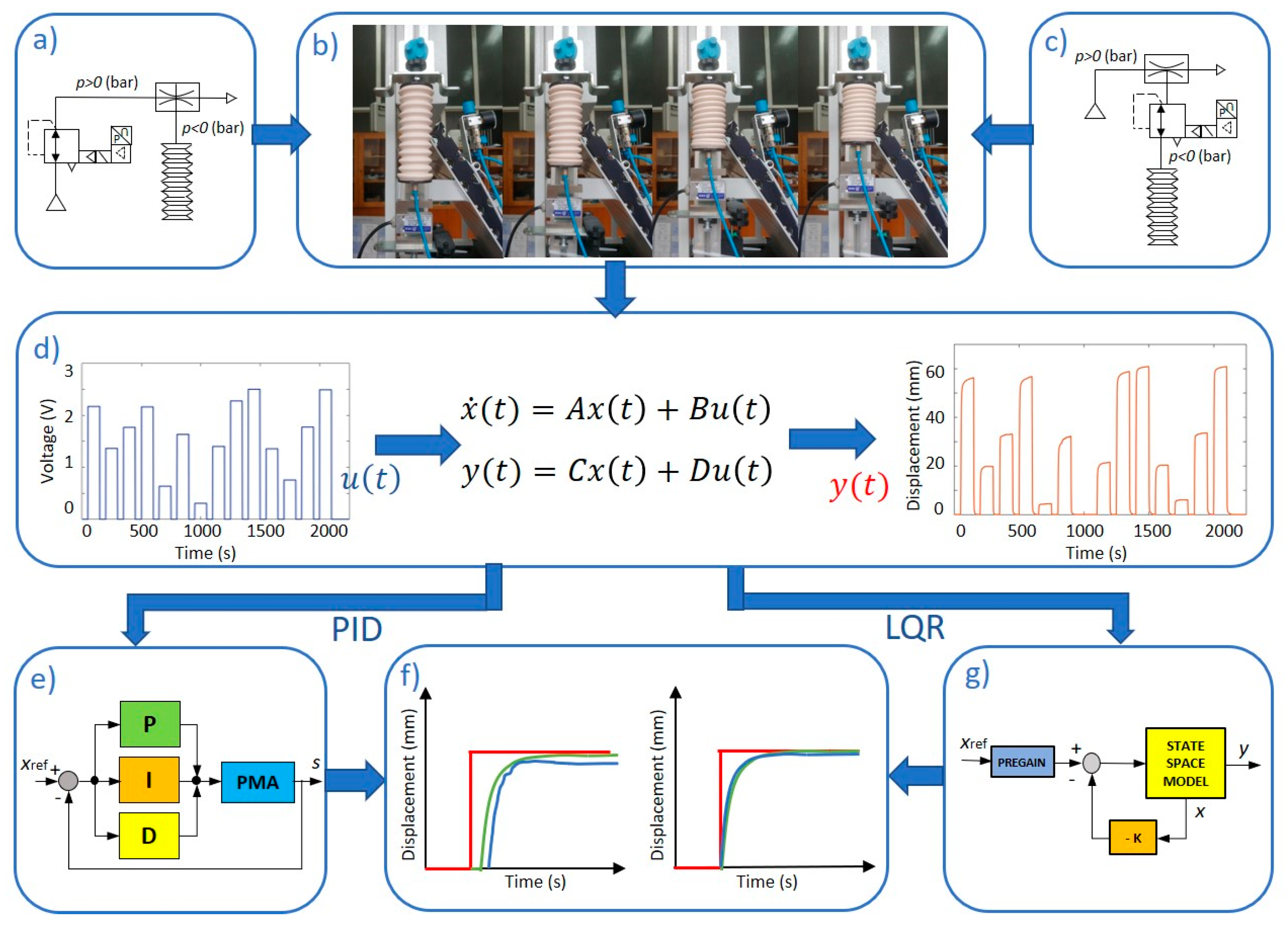
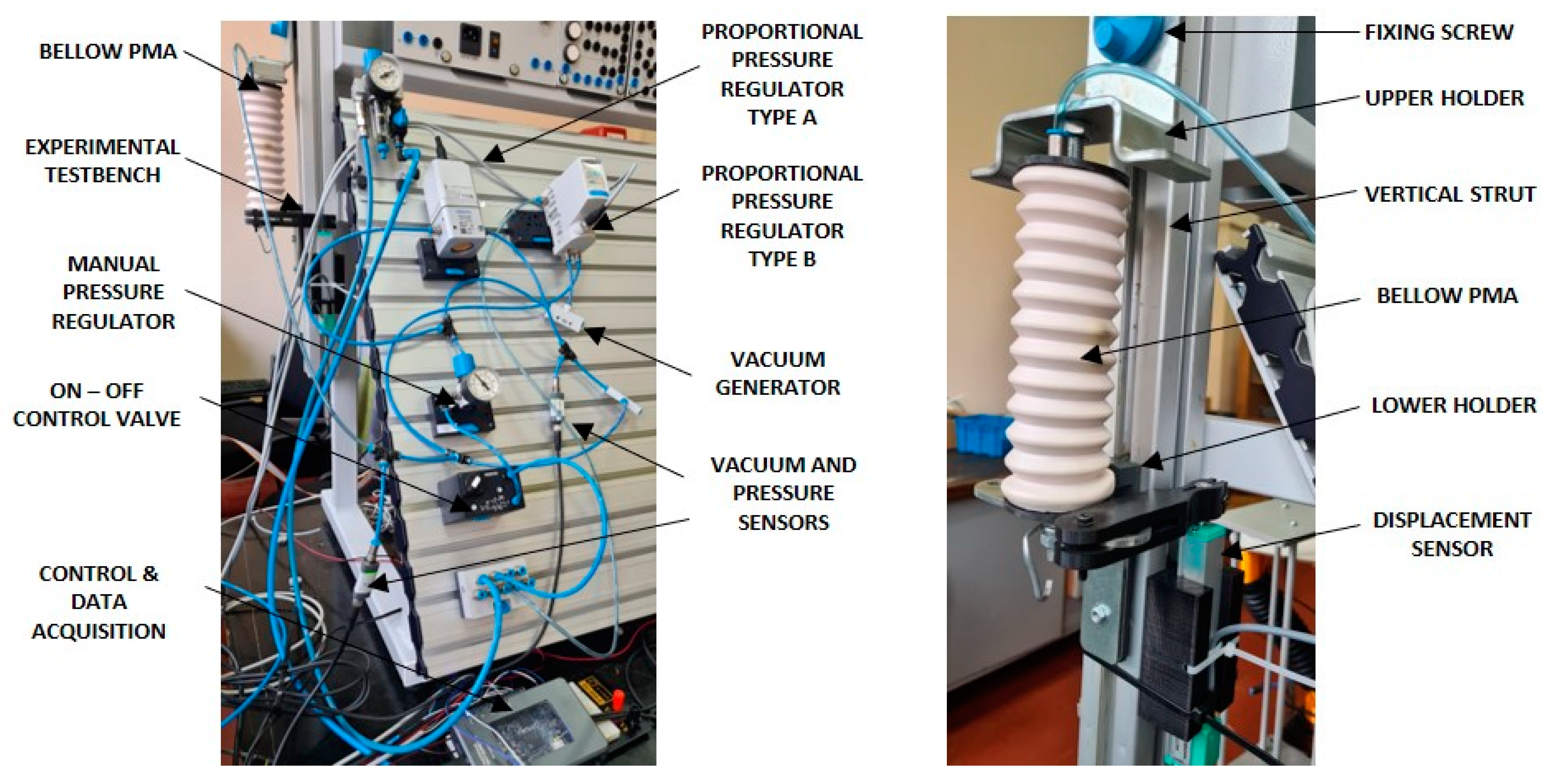
2.1. Experimental Apparatus

The experiments were carried out at the Laboratory for Hydraulic and Pneumatic Systems at the Faculty of Engineering, University of Rijeka. The testbed (Figure 2) was built from widely used strut profiles and contains a Planet Air L-S50-25 compressor, a FESTO LR-MICRO-MA40-Q4 manual pressure regulator, FESTO VPPE-3-1/8-6-010 and FESTO VPPI-5L-G18-1V1H-V1-S1D proportional pressure regulators and a FESTO VN-05-H-T2-PQ1-VQ1-RQ vacuum generator. The measuring equipment used for control and data acquisition consists of National Instruments NI myRIO 1900 device, Schmalz VS VP8 SA M8-4 vacuum and pressure sensors, and a Burster 8713-100 potentiometric displacement sensor.
The bellow PMA, whose development is described in detail in [10], is anchored to an upper holder that is fixed to the profile, and a lower holder that allows sliding linear motion on the strut profile. Additionally, the movable part of the potentiometric displacement sensor is attached to the lower profile. The vacuum generator function is based on the Venturi principle and for the used FESTO vacuum generator, an input value of 0 to 4 bar results in a vacuum range of 0 to −0.9 bar. Therefore, the input value of the air pressure was adjusted by a manual pressure regulator to the maximum value of p = 4 bar. The user application for data collection and control was developed in the LabVIEW programming environment as a Virtual Instrument (VI).
In contrast to previous work [10], here we conducted additional analyses of two different pneumatic system configurations with different vacuum control approaches (Figure 1a,c). In the first configuration, we used a proportional pressure regulator which we call type A in the following text (FESTO VPPE-3-1/8-6-010), with an output range from 0 to 8 bar to control the input pressure in the vacuum ejector (indirect vacuum control). In the second system, we employed a proportional pressure regulator named type B (FESTO VPPE-3-1/8-6-010), with a pressure output range from −1 to 1 bar for directional vacuum control at the vacuum generator output. These two systems were used and compared with the aim of analyzing dynamical properties of the PMAs used. Finally, the total energy consumption of the system was compared in these two distinct cases. The direct vacuum control was assumed to have better dynamical properties (i.e., faster response times) than the indirect approach, but this comes at the expense of more supplied air. That is, direct vacuum control method requires continuous vacuum generation, whereas the indirect principle uses air only when the proportional pressure regulator is triggered. Furthermore, the influence of switching times of both used pressure regulators was investigated.

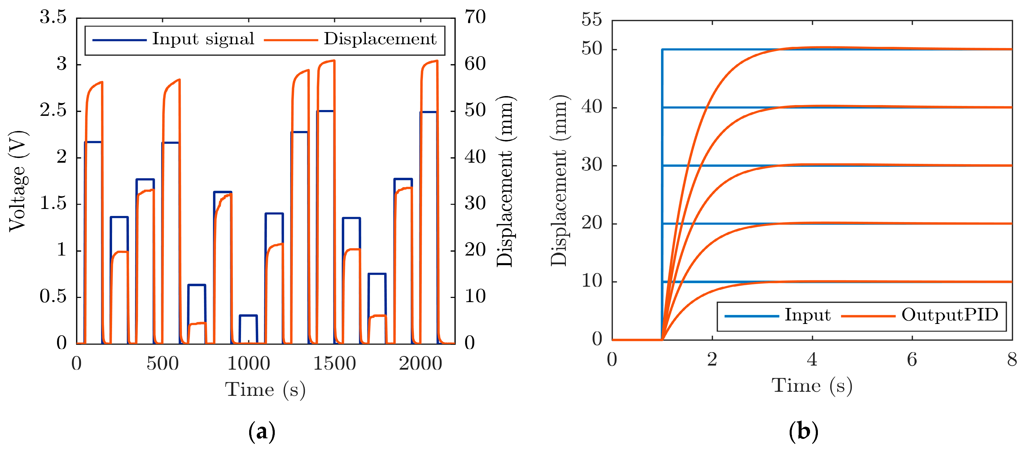
2.2. Numerical Modeling, PID Controller Development and Initial Experiments

With the aim of assessing the precision positioning parameters of the developed system, a widely used PID controller was employed first. Although a PID controller can ensure fast responses and a relatively low steady-state error, its response is generally characterized by some amount of overshoot.
The PID controller was custom-developed using the LabVIEW programming environment according to [21]. The algorithm is available on the author’s Github repository [22]. Its parameters were tuned by using Ziegler–Nichols closed-loop method and additionally refined by the trial-and-error method in the initial testing phase. The final values of the PID gains that produced satisfactory responses were KP = 0.115, KI = 0.015 and KD = 0.001. In the experimental phase, it was shown that increasing the reference value causes greater overshoot when such parameters are employed.
Taking into account the disadvantages of the mentioned tuning methods, in the next step we aimed to obtain a numerical model of the system. We selected the voltage of the proportional pressure regulator as the input and linear displacement of the PMA as the output. For the input signal, we employed step input signals with normally distributed amplitudes within a 0–2.5 V range. The upper limit was chosen since for this value, the system reaches its working range limit (0–61 mm) in the conditions with no external load. The sample time was set to 0.01 s. The duty cycle and period of the signal were set to 75% and 150 s, respectively. These parameters were chosen with respect to the dynamics of the open-loop system to account for the system’s over-damped behavior, as well as to capture its exact dynamical behavior. That is, the duty-cycle and period were chosen with respect to the time constants of the system in both directions of motion. The input signal generator script written in MATLAB can be found in the author’s Github repository [23].
The experiments with the system running in an open loop were performed using three different sets of randomly generated input signals. Figure 3a depicts an example of a typically obtained open-loop response. The MATLAB Identification Toolbox was then used to obtain the system’s transfer function based on the experimental data. Given that the system was overdamped, it could be approximated as a first order system:
G s = 10.6 s + 0.5834
It was found that the R2 is equal to 0.655. After the model was built, a corresponding PID controller was found by using the SIMULINK PID tuning toolbox and the corresponding simulated responses to different set-point values were recorded, as shown in Figure 3b. It can be noticed that the steady-state error is nearly zero, while the overshoot of the system is negligible for smaller reference values, and very little for the larger references.
Due to the limitations of the PID implemented in SIMULINK, where the derivative component of error is filtered by using a low pass filter to avoid the effect of derivative kicks, we modified the derivative part in the implementation of the PID on a real-time hardware setup such that the derivative gain multiplies process value only [24]. Therefore, we adopted proportional (KP = 0.16) and integral (KI = 0.11) gains obtained in SIMULINK while we experimentally found a new derivative gain (KD = 100) that provides a response with no or very little overshoot for different reference values within the working range. The PMA was then subjected to experimental tests without using an external load, as shown in Figure 4.
It can be seen that the overshoot is negligible in all cases, which corresponds to the simulated responses (Figure 3b). A steady-state error from a control perspective (later in the text denoted simply as error), on the other hand, increases with muscle contraction, and can reach up to 1.5 mm for higher reference values. It is also noticeable that the PMA takes a longer time to return to its initial position (its maximum length). Furthermore, almost always, the muscle does not return to its initial position, because there is always a small amount of residual vacuum left in the body of the muscle. The aforementioned behavior is also influenced by the slower valve response time during its switch-off phase which is a result of the dynamics of the spring used to return the piston of the proportional pressure regulator to its initial position.
Given that the PID controller was unable to ensure optimal response, it was decided that the LQR approach will be investigated in the following steps with the attempt of minimizing steady-state error.

2.3. Numerical Modeling, LQR Controller Development and Initial Experiments
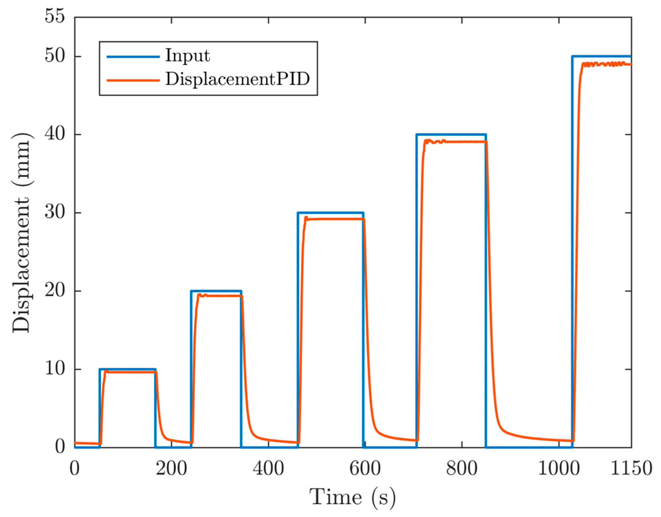
In order to apply an LQR approach to the considered system, additional sets of experiments were performed (using the parameters defined in Section 2.2) and the MATLAB Identification Toolbox was again employed to obtain the mathematical model of the system. In all cases, a sampling time of 5 ms was used. The second order state-space model in observable canonical form was, thus, developed. Linear displacement and velocity were used as states. The model was then used as a base for building an LQR controller. Based on previous research [10] and numerical simulations performed on the developed model, for the calculation of LQR gains, matrix Q was chosen to be an identity matrix multiplied by 10, while R was set to 0.001. By solving Riccati’s equation [25], a vector of gains K = [0.11 0.01] was obtained. The LQR controller was then implemented in the LabVIEW programming environment. Linear displacement was measured by employing a linear displacement sensor, and velocity was calculated from displacement by using shift registers in LabVIEW. The velocity was calculated in each consecutive time step as the difference between current and previous displacement values divided by sampling time. Finally, to reduce the effect of noise, the average velocity was calculated in real-time as the moving average of the previous five velocity values. Performed point-to-point positioning experiments allowed us to establish that a considerable steady-state error is present due to the inherent nonlinearity of the system, the compressibility of air and PMA’s different behavior depending on the direction of motion, as discussed in Section 2.2. Therefore, a data-driven nonlinear pregain term that modifies the reference signal was determined experimentally and introduced into the system. Based on the performed experimental measurements, two 2nd order polynomials were determined each for one direction of motion. Table 1 shows the coefficients of each polynomial with respect to the direction of motion, whereas coefficient a multiplies the highest order member. These functions (Figure 5) were used to modify the reference signal so as to minimize the steady-state error. They were implemented in the LabVIEW environment by using a state-machine approach.
Figure 6 depicts the positioning performances of the developed LQR with pregain in no-load conditions. When the results are compared to those obtained by using the PID (Figure 4), it can be observed better dynamical behavior is obtained since the responses for each reference input are less jittery in close proximity to the steady state. Another clear advantage of using the LQR with pregain is a considerably lower steady-state error (0.03–0.14 mm) when compared to the results achieved with PID (0.1–1.5 mm).
Furthermore, in the case of LQR, overshoot is virtually eliminated. As in the case when PID is used, it can be seen that the muscle does not return exactly to the initial position, since there is always a small amount of residual vacuum left in the body while all experiments are performed without applying an external load.

3. Results

In this section, we compare the positioning performances of two different vacuum sources using PID and LQR control methods. First, we perform experiments with no external load, and then we add a constant load of 500 g to the system.

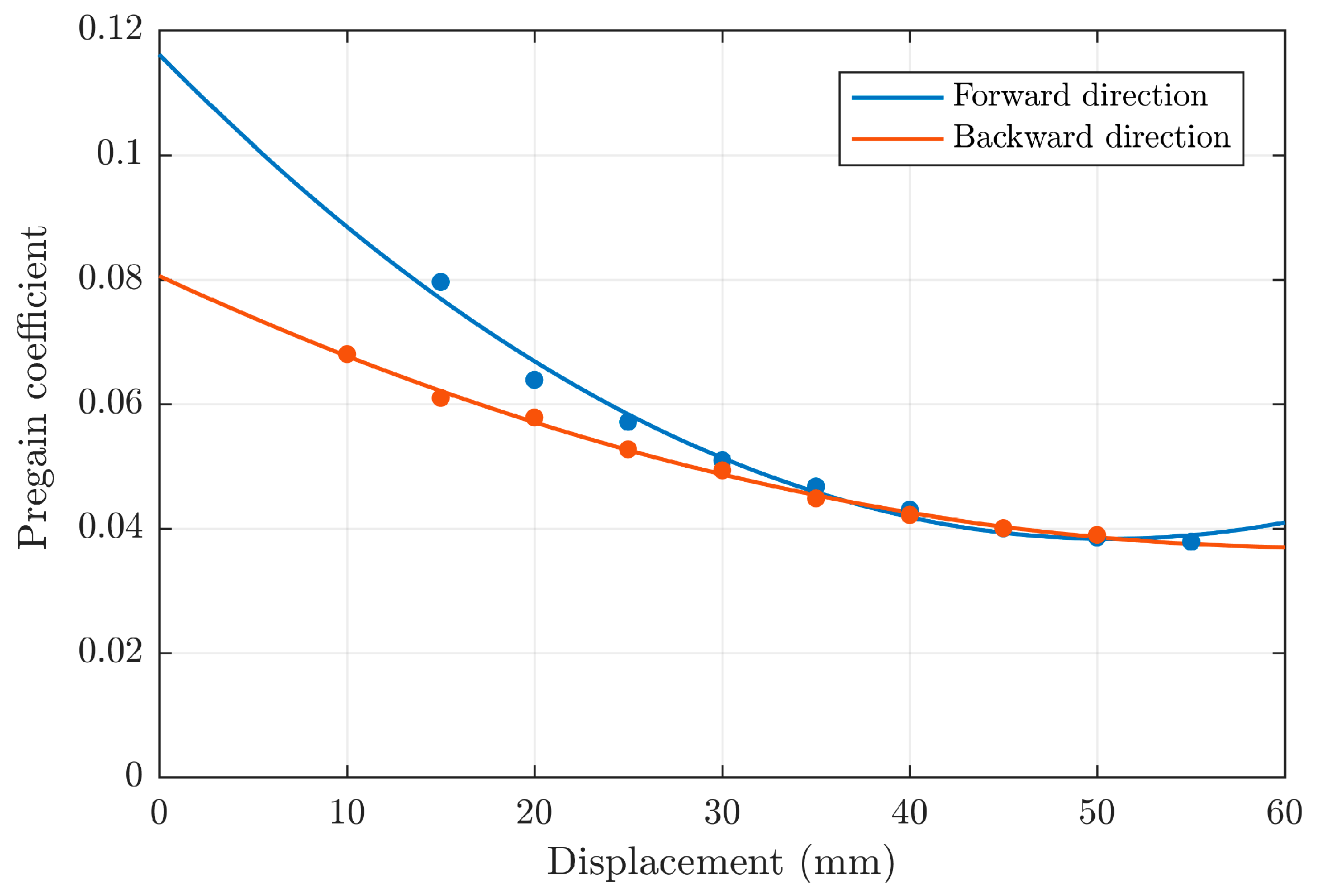
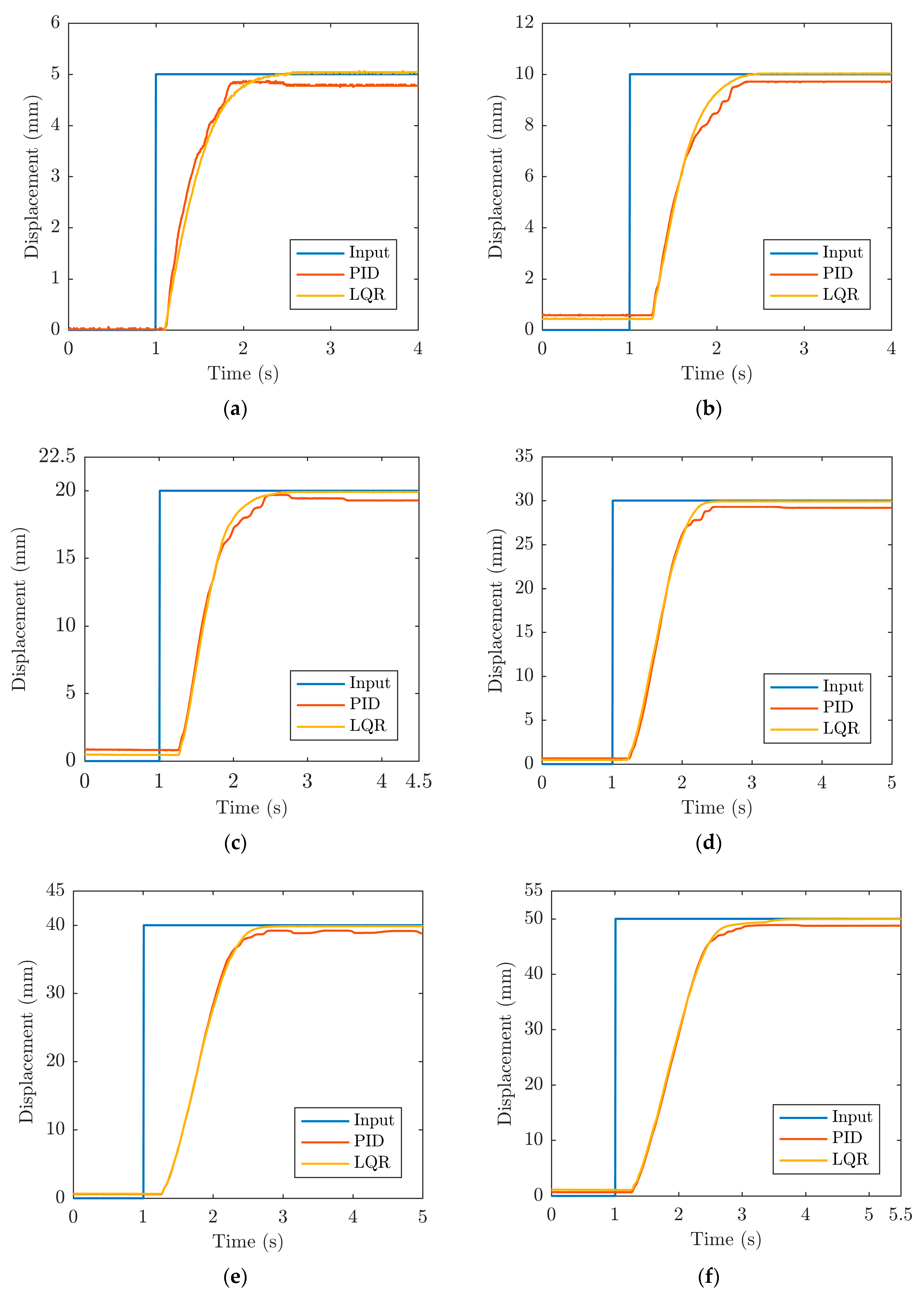
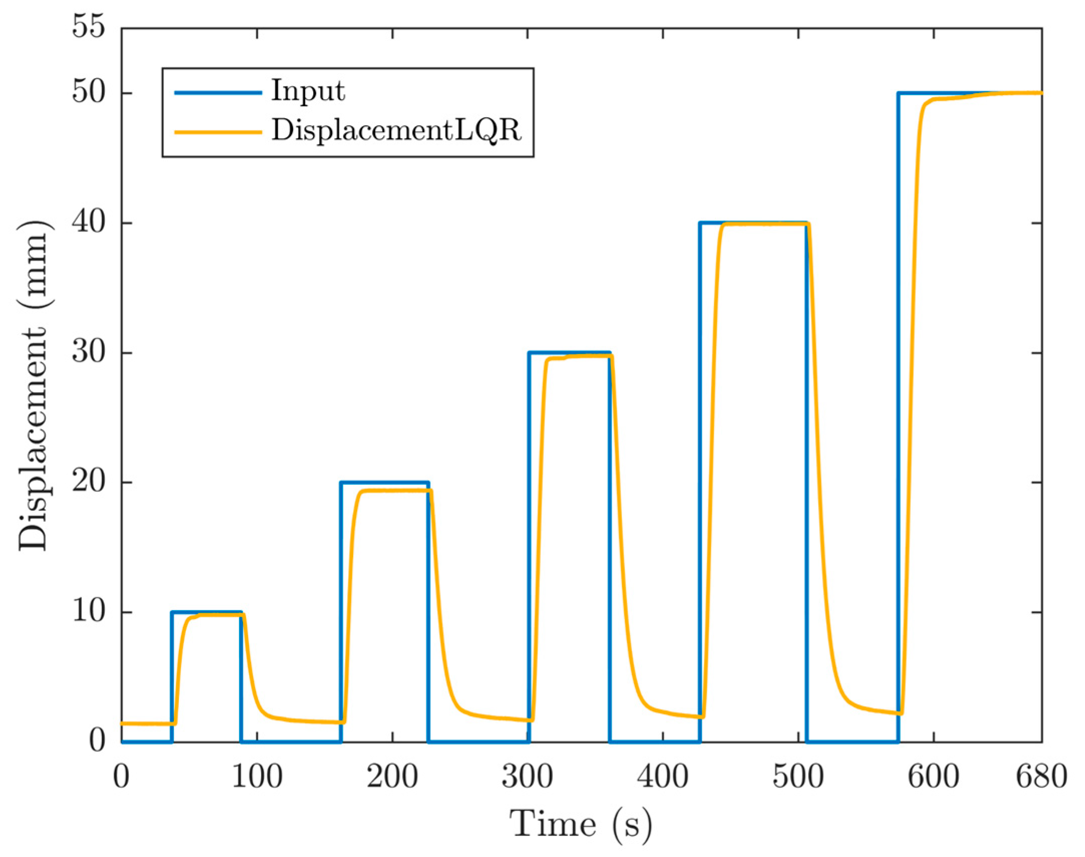
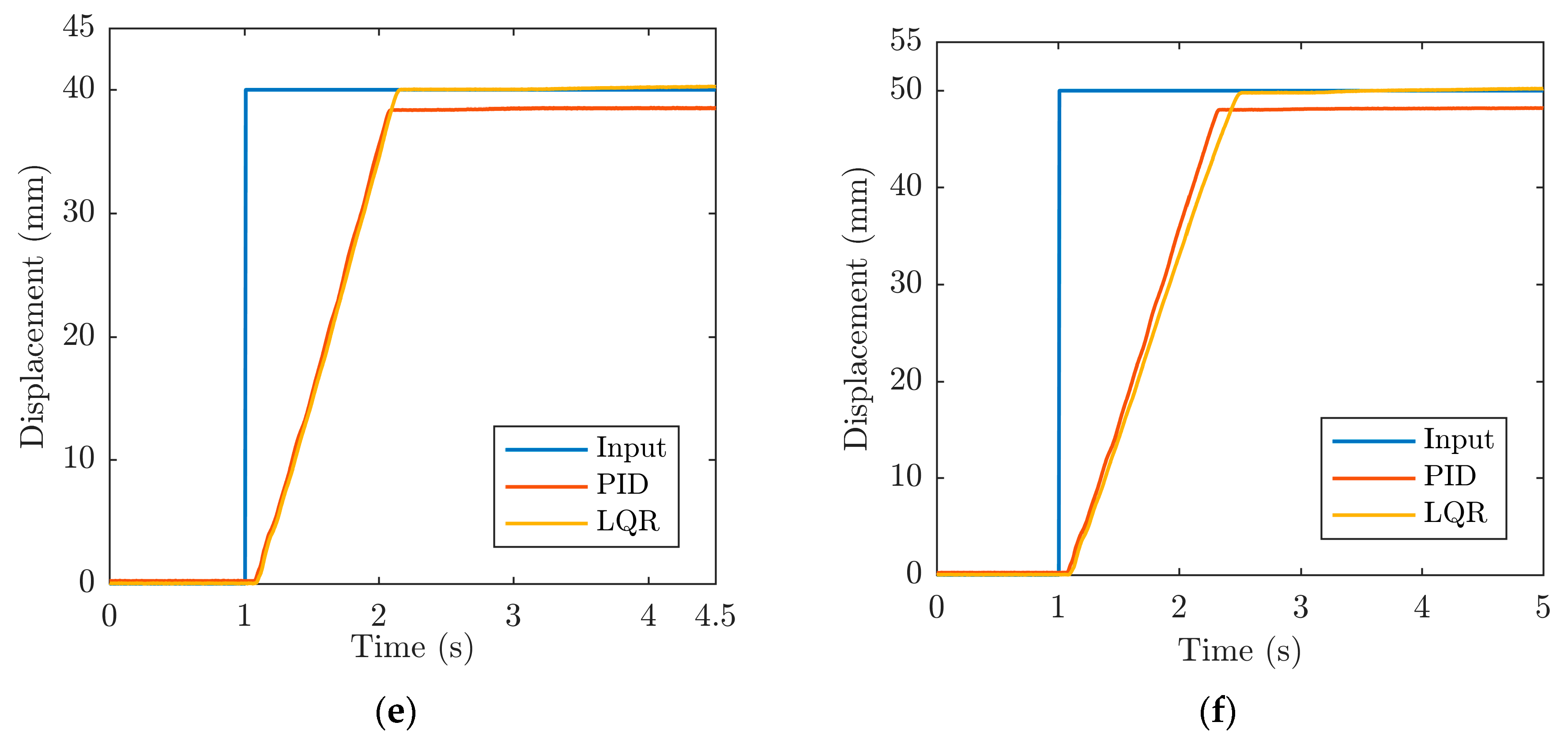
3.1. Position Performances of the Bellow PMA by Utilizing Indirect Vacuum Control

The PMA responses in no-load conditions are recorded for the PID and LQR approaches for different reference values (5, 10, 20, 30, 40 and 50 mm). Please keep in mind that, while it has been demonstrated that the working range of the employed PMA can be extended to approximately 60 mm [10], we limit the working range to 50 mm in this paper to avoid the contact of the inner supporting rings which can introduce additional nonlinearity to the setup.
As previously stated, in the case of indirect vacuum control (type A—please refer to Section 2.1 and Figure 1a), the proportional regulator varies the output pressure at the input rail of the used ejector, creating vacuum at its output. In this case, we experimentally confirmed that there is some dead-band present in the PMA response, as it can be observed from Figure 7. It can also be seen that the PMA has very similar dynamical behavior for both PID and LQR, though PID shows slightly faster dynamics for 5, 20 and 40 mm reference values. Steady-state error is, however, always considerably lower when LQR is used and this result is mainly limited by the used feedback sensor. In some cases, LQR outperforms PID by an order of magnitude, while the error is kept to a few tens of micrometers for all reference values. However, for both control typologies, there is a tendency for steady-state error to increase with higher reference values (except for the highest reference in case of LQR). When compared to similar research in this field [19], where error is measured in millimeters, this can be considered as a very good result, especially given that it was achieved on a highly nonlinear pneumatic system. Please note that the achieved positioning results are also limited by the properties of the used sensor (see also Section 2). Both controllers provide responses without overshoot, but the jitter effect is pronounced when PID is used. Similar to previous experiments, the muscle does not return exactly to the reference position, since all experiments are performed without the application of an external load. Table 2 summarizes the values of rising times and steady-state errors.
Given the fact that there is always a certain amount of dead-band present in the responses when indirect vacuum control is used, we analyze the behavior of the system by employing direct vacuum control in the following section.

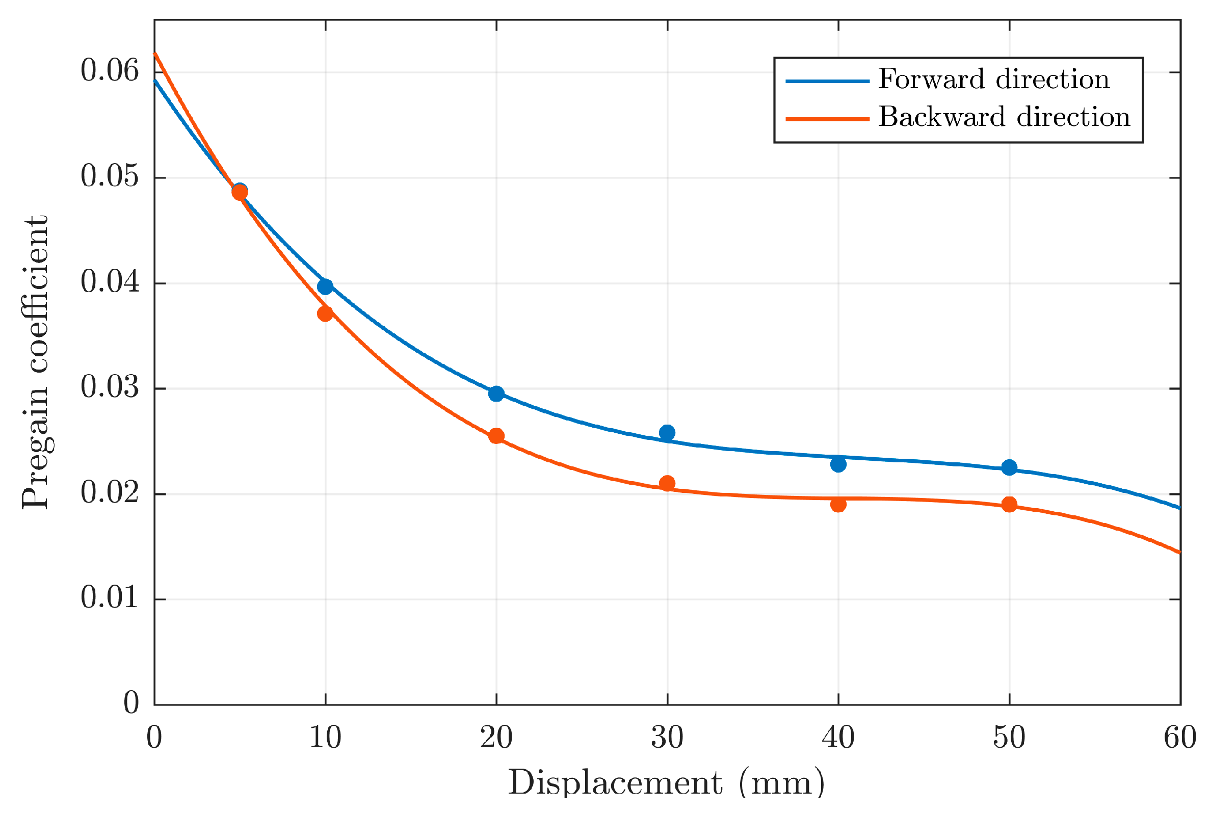
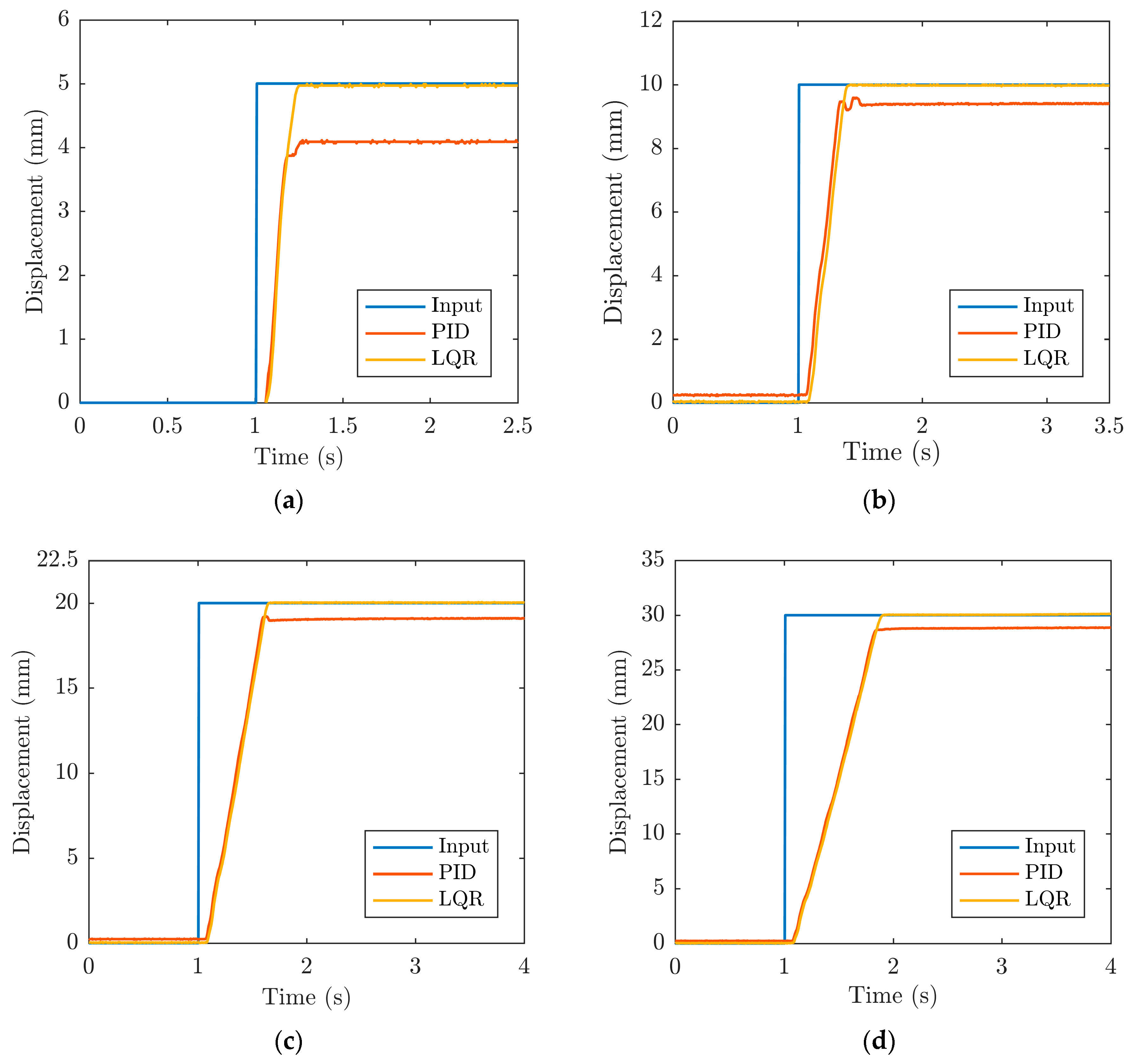
3.2. Position Performances of the Bellow PMA by Utilizing Direct Vacuum Control

In this section, we conduct the experiments by using the type B pneumatic system (see Figure 1c), which allows for direct vacuum control at the output of the ejector. This configuration also allows for much faster valve switching (approximately 3 Hz frequency). Please keep in mind that one of the disadvantages of this system is that it consumes more energy due to the need for constant vacuum supply to the valve.
Since the system’s hardware has been considerably modified, the optimal gains of both utilized controllers had to be adjusted. The PID parameters that were adopted are as follows: KP = 0.295, KI = 0.035 and KD = 3. The vector with LQR gains, on the other hand, is calculated to be K = [0.2 0.002]. As with the type A system, we also calculate an additional pregain term in this case to allow for the elimination of the steady-state error. As shown in Table 3, the pregain term (Figure 8) is defined as a third order polynomial with coefficients that again depend on the motion direction.
Figure 9 depicts and compares the experimental results for both control typologies when no external load is applied.
From the experimental results, it can be seen that the overshoot is not present when LQR is employed. For the lowest reference value, the PID controller induces an overshoot of approximately 6% (Figure 9a). Moreover, the previously observed dead-band is almost completely diminished in this case. Besides that, the faster switching time allows for a much faster overall system response for both PID and LQR controllers, which once more justifies the need of using the direct vacuum control principle if faster dynamics is desired. It can be noticed that the PMA has very similar dynamics for both control typologies, though PID again has slightly lower rising time constants for some reference values. Steady-state error is, however, always much lower in the case of LQR. LQR outperforms PID in terms of steady-state error by an order of magnitude in most cases (except for the 10 mm reference), while the error is a few tens of micrometers for all reference values. Table 4 summarizes the values of rising times and steady-state errors.
On the other hand, when the results are compared to those of type A system (Table 5), it can be observed that when the PID controller is used, the rising time constant is considerably lower for smaller reference values and slightly higher (4%) for the highest reference value when type B system is considered. The steady-state error is significantly lower for almost all references, with the exception of the lowest reference value (5 mm) where it is much higher in the case of the system with type B vacuum control. This behavior can be attributed to the highly nonlinear behavior of the analyzed pneumatic muscle.
Rising time constants are lower in all cases when using the LQR controller, and this is especially noticeable for lower reference values. Except for the highest reference value, steady-state error is again much lower in almost all cases.
Finally, the experimental results obtained by employing an experimental system with direct vacuum control (type B) allowed establishing significantly better results from a dynamical point of view. This is especially evident taking into account the fact that the dead-band effect during PMA activations is almost eliminated. Moreover, if compared to type A, the dynamical response is much faster especially for lower reference values. The steady-state error is in the case of LQR again several tens of micrometers (20–80 µm).
In order to test the muscle in more realistic conditions, we assess the positioning performances of the loaded system in the final set of experiments. The system is given a constant weight of 500 g. The results of the positioning performances for the loaded system are shown in Figure 10, while the achieved dynamical performances are again evaluated in terms of rising time constants for each reference value, as shown in Table 6. The graphs show that positioning performances without overshoot in the case of LQR and with slight overshoot for some references in the case of PID, are achieved. In both cases, a very small dead-band value is obtained at the beginning of the actuation cycle. When the rising time constants are compared to those achieved in the previous experiments, it can be concluded that the values are very similar and only differ by about 10%.
However, when using a PID controller, the steady-state error is much higher when the system is loaded, and this is especially evident for the lower references. This means that if the loading conditions change, the PID parameters have to be tuned again [13]. This once more justifies the need for using more refined control typologies. When LQR with an additional pregain term is used, on the other hand, the steady-state error is a few tens of micrometers and it is not substantially influenced by external loading.
Finally, we conducted energy consumption analyses for the pneumatic systems under consideration by measuring the time required for the pressure in the compressor’s air reservoir to drop by 2 bar during the PMA operation. In both systems, the input pressure is held constant at 4 bar, and the control signal to the valves is sinusoidal with 0.01 Hz frequency. In these conditions, the total time measured was 870 and 264 s for type A (indirect vacuum control) and type B (direct vacuum control) systems, respectively. This allowed us to establish that the direct vacuum control system consumes 70% more compressed air than the indirect vacuum control approach. The direct vacuum control approach, however, allows better dynamical behavior, i.e., a faster response.

4. Conclusions

In the presented research, we demonstrated the possibility of precision positioning by using PID and LQR control approaches of a custom-designed bellow PMA actuator. Two distinct vacuum control configurations were investigated; a type A system that performs indirect vacuum control and a type B system that allows direct vacuum control. The data-driven numerical model of the system was developed using MATLAB. Both control algorithms were developed and tested in the simulation environment using the developed numerical model. The LabVIEW programming environment was then used to develop the algorithms for real-time control.
After initial evaluation of the system, both vacuum control systems were thoroughly evaluated by using PID and LQR control approaches. In almost all cases, the steady-state error of the LQR was an order of magnitude lower than that of the PID controller. The LQR approach also outperformed PID in terms of smaller overshoot. The response velocity for both control algorithms was comparable. When external load was added to the system, steady-state error increased significantly when the PID controller was used. LQR, on the other hand, successfully minimized error when the load was added and kept it within micrometric boundaries. A comparison of direct and indirect vacuum control approaches revealed that direct vacuum control allows significantly faster dynamical behavior. Furthermore, we performed energy consumption analyses for the pneumatic systems used and showed that the direct vacuum control consumes up to 70% more air than the indirect vacuum control approach.
Finally, the presented research demonstrated that the analyzed artificial muscle can achieve a positioning error of a few tens of micrometers (which is mainly limited by the used sensor) despite its highly nonlinear behavior. An additional design optimization could be performed to the muscle to refine the results across its entire working range.
Future research will concentrate on developing a 3-DOF motion (Stewart) platform with pneumatic muscle actuators and the LQR control approach described in this paper. Special attention will be given to the type of the 3D motion detection sensors during the design phase to ensure proper feedback.

Author Contributions

Conceptualization, G.G. and E.K.; methodology, G.G., E.K., A.Š. and S.P.; software, A.Š. and S.P.; validation, G.G., E.K., A.Š. and S.P.; formal analysis, A.Š. and S.P.; investigation, A.Š. and S.P.; resources, G.G., E.K., A.Š. and S.P.; data curation, A.Š.; writing—original draft preparation, G.G. and E.K.; writing—review and editing, G.G. and E.K.; visualization, G.G. and A.Š.; supervision, G.G. and E.K.; funding acquisition, G.G. and E.K. All authors have read and agreed to the published version of the manuscript.

Funding

This research received no external funding.

Institutional Review Board Statement

Not applicable.

Informed Consent Statement

Not applicable.

Data Availability Statement

Not applicable.

Conflicts of Interest

The authors declare no conflict of interest.

References

  1. Su, H.; Hou, X.; Zhang, X.; Qi, W.; Cai, S.; Xiong, X.; Guo, J. Pneumatic soft robots: Challenge and benefits. Actuators 2022, 11, 92. [Google Scholar] [CrossRef]
  2. Walker, J.; Zidek, T.; Harbel, C.; Yoon, S.; Strickland, F.S.; Kumar, S.; Shin, M. Soft robotics: A review of recent developments of pneumatic soft actuators. Actuators 2020, 9, 3. [Google Scholar] [CrossRef]
  3. Majidi, C. Soft Robotics: A Perspective—Current Trends and Prospects for the Future. Soft Robot. 2014, 1, 5–11. [Google Scholar] [CrossRef]
  4. Dong, W.; Wang, Y.; Zhou, Y.; Bai, Y.; Ju, Z.; Guo, J.; Gu, G.; Bai, K.; Ouyang, G.; Chen, S.; et al. Soft human-machine interfaces: Design, sensing and simulation. Int. J. Intell. Robot. Appl. 2018, 2, 313–338. [Google Scholar] [CrossRef]
  5. Yu, M.; Cheng, X.; Peng, S.; Cao, Y.; Lu, Y.; Li, B.; Feng, X.; Znang, Y.; Wang, H.; Jiao, Z.; et al. A self-sensing soft pneumatic actuator with closed-loop control for haptic feedback wearable devices. Mater. Des. 2022, 223, 111149. [Google Scholar] [CrossRef]
  6. Pan, M.; Yuan, C.; Liang, X.; Dong, T.; Liu, T.; Zhang, J.; Zou, J.; Yang, H.; Bowen, C. Soft Actuators and Robotic Devices for Rehabilitation and Assistance. Adv. Intell. Syst. 2022, 4, 2100140. [Google Scholar] [CrossRef]
  7. Belforte, G.; Eula, G.; Ivanov, A.; Sirolli, S. Soft Pneumatic Actuators for Rehabilitation. Actuators 2014, 3, 84–106. [Google Scholar] [CrossRef]
  8. Kamenar, E.; Črnjarić-Žic, N.; Haggerty, D.; Zelenika, S.; Hawkes, E.; Mezić, I. Prediction of the behavior of a pneumatic soft robot based on Koopman operator theory. In Proceedings of the 2020 43rd International Convention on Information, Communication and Electronic Technology, Opatija, Croatia, 28 September–2 October 2020. [Google Scholar]
  9. Tanaka, J.; Ogawa, A.; Nakamoto, H.; Sonoura, T.; Eto, H. Suction pad unit using a bellows pneumatic actuator as a support mechanism for an end effector of depalletizing robots. Robomech J. 2020, 7, 2. [Google Scholar] [CrossRef]
  10. Gregov, G.; Ploh, T.; Kamenar, E. Design, Development and Experimental Assessment of a Cost-Effective Bellow Pneumatic Actuator. Actuators 2022, 11, 170. [Google Scholar] [CrossRef]
  11. Petre, I.M. Studies regarding the Use of Pneumatic Muscles in Precise Positioning Systems. Appl. Sci. 2021, 11, 9855. [Google Scholar] [CrossRef]
  12. Xavier, M.S.; Fleming, A.J.; Yong, Y.K. Design and Control of Pneumatic Systems for Soft Robotics: A Simulation Aproach. IEEE Robot. Autom. Lett. 2021, 6, 5800–5807. [Google Scholar] [CrossRef]
  13. Tang, T.F.; Chong, S.H.; Chan, C.Y.; Sakthivelu, V. Point-to-Point Positioning Control of a Pneumatic Muscle Actuated System Using Improved-PID Control. In Proceedings of the 2016 IEEE International Conference on Automatic Control and Intelligent Systems (I2CACIS), Selangor, Malaysia, 22 October 2016. [Google Scholar]
  14. Al-Ibadi, A.; Nefti-Meziani, S.; Davis, S. Controlling of Pneumatic Muscle Actuators Systems by Parallel Structure of Neural Network and Proportional Controllers (PNNP). Front. Robot. AI 2020, 7, 115. [Google Scholar] [CrossRef]
  15. Zhao, J.; Zhong, J.; Fan, J. Position Control of a Pneumatic Muscle Actuators Using RBF Neural Network Tuned PID Controller. Math. Probl. Eng. 2015, 2015, 810231. [Google Scholar] [CrossRef]
  16. Scaff, W.; Horikawa, O.; Tsuzuki, M.S. Pneumatic Artificial Muscle Optimal Control with Simulated Annealing. IFAC 2018, 51, 333–338. [Google Scholar] [CrossRef]
  17. Nuchkrua, T.; Leephakpreeda, T. Fuzzy Self-Tuning PID Control of Hydrogen-Driven Pneumatic Artificial Muscle Actuator. J. Bionic Eng. 2013, 10, 329–340. [Google Scholar] [CrossRef]
  18. Šitum, Ž.; Herceg, S.; Bolf, N.; Željka, U.A. Design, Construction and Control of a Manipulator Driven by Pneumatic Artificial Muscles. Sensors 2023, 23, 776. [Google Scholar] [CrossRef] [PubMed]
  19. Kazemi, S.; Hashem, R.; Stommel, M.; Cheng, L.K.; Xu, W. Experimental Study on the Closed-Loop Control of a Soft Ring-Shaped Actuator for In-Vitro Gastric Simulator. IEEE/ASME Trans. Mechatron. 2022, 27, 3548–3558. [Google Scholar] [CrossRef]
  20. Conte, G.Y.C.; Marques, F.G.; Garcia, C. LQR and PID Control Design for a Pneumatic Diaphragm Valve. In Proceedings of the IEEE International Conference on Automation/XXIV Congers of the Chilean Association of Automatic Control (ICA-ACCA), Valparaiso, Chile, 22–26 March 2021. [Google Scholar]
  21. Baćac, N.; Slukić, V.; Puškarić, M.; Štih, B.; Kamenar, E.; Zelenika, S. Comparison of different DC motor positioning control algorithms. In Proceedings of the 2014 37th International Convention on Information and Communication Technology, Electronics and Microelectronics (MIPRO), Opatija, Croatia, 26–30 May 2014; pp. 1654–1659. [Google Scholar]
  22. Control_Algorithms. Available online: https://github.com/ekamenar/control_algorithms (accessed on 6 February 2023).
  23. Signal_Generator. Available online: https://github.com/ekamenar/signal_generator (accessed on 6 February 2023).
  24. Kamenar, E.; Zelenika, S. Micropositioning mechatronics system based on FPGA architecture. In Proceedings of the 2013 36th International Convention on Information and Communication Technology, Electronics and Microelectronics (MIPRO), Opatija, Croatia, 20–24 May 2013; pp. 125–130. [Google Scholar]
  25. Levine, W.S. The Control Handbook; Three Volume Set; CRC Press: Boca Raton, FL, USA, 2018. [Google Scholar]
Figure 1. The development and experimental evaluation of PID and LQR controllers: (a) schematic view of the pneumatic setup for indirect vacuum control; (b) working principle of the bellow PMA; (c) schematic view of the pneumatic setup for direct vacuum control; (d) numerical model identification; (e) schematic model of the PID controller; (f) experimental assessment of position control for indirect (left) and direct (right) vacuum control; (g) simplified model of the LQR controller.
Actuators 12 00073 g001
Figure 2. The main components of the experimental setup.
Actuators 12 00073 g002
Figure 3. (a) The system’s open-loop response for an input data set with normally distributed amplitudes in the 0–2.5 V range, corresponding to a displacement range of 0–61 mm. (b) Simulated responses of the PID controlled system for different reference values in SIMULINK.
Actuators 12 00073 g003
Figure 4. Positioning performance of the PMA controlled by PID.
Actuators 12 00073 g004
Figure 5. Controller pregain for the type A system represented as two 2nd order polynomials.
Actuators 12 00073 g005
Figure 6. Positioning performances of the developed LQR controller.
Actuators 12 00073 g006
Figure 7. Results of PMA position control with PID (red lines) and LQR (yellow lines) for the type A pneumatic experimental setup: (a) 5 mm; (b) 10 mm; (c) 20 mm; (d) 30 mm; (e) 40 mm; (f) 50 mm reference.
Actuators 12 00073 g007
Figure 8. Controller pregain for type B system represented as two third order polynomials.
Actuators 12 00073 g008
Figure 9. Results of PMA position control with PID (red lines) and LQR (yellow lines) for the second pneumatic experimental setup: (a) 5 mm; (b) 10 mm; (c) 20 mm; (d) 30 mm; (e) 40 mm; (f) 50 mm reference.
Actuators 12 00073 g009
Figure 10. Results of PMA position control with PID (red lines) and LQR (yellow lines) for the second pneumatic experimental setup with 500 g load: (a) 5 mm; (b) 10 mm; (c) 20 mm; (d) 30 mm; (e) 40 mm; (f) 50 mm reference.
Actuators 12 00073 g010aActuators 12 00073 g010b
Table 1. Nonlinear pregain term polynomial coefficients for the type A pneumatic system.
Motion Directionabc
Forward3.03 × 10−5−3.07 × 10−31.161 × 10−1
Backward1.1 × 10−5−1.4 × 10−38.057 × 10−2
Table 2. Rising time constants and steady-state errors for the type A pneumatic system for different set points.
τs (s)Steady-State Error (µm)
Displacement (mm)PIDLQRPIDLQR
50.640.67522717
100.850.64429130
200.8650.66562090
300.7050.725830100
400.860.891000140
501.011.03123030
Table 3. Nonlinear pregain term polynomial coefficients for the type B pneumatic system.
Motion Directionabcd
Forward−4.6 × 10−75.724 × 10−5−2.442 × 10−15.929 × 10−2
Backward−6 × 10−77.65 × 10−5−3.11 × 10−36.188 × 10−2
Table 4. Rising time constants and steady-state errors for the type B pneumatic system for different set points.
τs (s)Steady-State Error (µm)
Displacement (mm)PIDLQRPIDLQR
50.0950.164217
100.1850.20514480
200.420.4438010
300.650.62552050
400.860.8473020
501.051.00596050
Table 5. Comparison of rising time constants and steady-state errors for indirect (A) and direct (B) vacuum control.
τsSteady-State Error
Displacement (mm)PIDB vs. PIDAPIDB vs. PIDAPIDB vs. PIDAPIDB vs. PIDA
585% less85% less65% moresame
1069% less69% less50% less62% more
2048% less34% less39% less90% less
308% less14% less38% less50% less
40same6% less28% less85% less
504% more2% less22% less40% more
Table 6. Rising time constants and steady-state errors for the type B pneumatic system and a load of 500 g for different set points (in seconds).
τs (s)Steady-State Error (µm)
Displacement (mm)PIDLQRPIDLQR
50.2050.1291132
100.230.22560827
200.4350.4489030
300.630.635115040
400.830.83141030
501.0151.085179070
Disclaimer/Publisher’s Note: The statements, opinions and data contained in all publications are solely those of the individual author(s) and contributor(s) and not of MDPI and/or the editor(s). MDPI and/or the editor(s) disclaim responsibility for any injury to people or property resulting from any ideas, methods, instructions or products referred to in the content.

