Article

Armature Structure Optimization of Annular Multipole Solenoid Valves Based on Electromagnetic Force Distribution

1
School of Naval Architecture, Ocean and Energy Power Engineering, Wuhan University of Technology, Wuhan 430063, China
2
National Engineering Laboratory for Marine and Ocean Engineering Power System, Electronic Control Sub-Laboratory for Low-Speed Engine, Wuhan 430063, China
3
Key Laboratory of Marine Power Engineering and Technology Granted by MOT, Wuhan 430063, China
*
Author to whom correspondence should be addressed.
Actuators 2023, 12(2), 54; https://doi.org/10.3390/act12020054
Submission received: 3 December 2022 / Revised: 14 January 2023 / Accepted: 20 January 2023 / Published: 26 January 2023
(This article belongs to the Section Precision Actuators)

Abstract

:
To improve the dynamic response speed of high-speed solenoid valves in electric fuel injection systems of marine diesel engines, a numerical simulation model of the solenoid valve is described in this paper. The accuracy of the simulation model was verified on the test bed of the solenoid valve. The effect of the punch position and the size of the dynamic response of the solenoid valve were investigated by using the distribution law of the electromagnetic force in the armature. The results of the test showed that armature drilling in the inter-yoke zone can optimize the solenoid closing response time, but it has little impact on the solenoid opening response time. From this rule, two groove schemes were further designed. Through comparison and calculation, it can be concluded that the fan groove scheme is better than the trapezoidal groove scheme, and that the opening and closing response times of the solenoid valve should be targeted in order to multi-target optimize the fan groove geometric parameters and the armature thickness. The results show that after optimization, the weight of the motion part is reduced by 21.6%, the opening response time of the solenoid valve is reduced by 11.1%, and the closing response time is reduced by 30.0%. While reducing the oil film damping of the armature motion, the overall dynamic response characteristics of the solenoid valve are improved.

1. Introduction

Due to its high thermal efficiency, strong adaptability, safe operation, and high dependability, high-power diesel engines are frequently employed in ship, heavy vehicle, and engineering machinery industries. With stricter regulations on fuel consumption and emissions, many advanced technologies, such as turbocharging [1,2], exhaust gas recirculation [3,4], advanced combustion chambers [5,6,7], advanced combustion mode [8,9,10], electronic high pressure fuel systems [11,12], and post-treatment technology [13], have been applied to diesel engines. Electronic high-pressure fuel systems may not only increase the atomization quality of the fuel in the cylinder, but they can also precisely manage the fuel injection quantity and the injection timing, all of which can optimize the combustion process. As a result, electronic high pressure fuel systems are extensively employed and explored.
According to the injection control signals supplied by the electronic control unit (ECU), the solenoid valve implements injection control in the common-rail system. The control signals are converted in this procedure from electromagnetic to mechanical to liquid in order to regulate the injector’s needle valve operation. The secret to precise control of the injection time, the injection duration, and the multiple injections is therefore found in the solenoid valve response characteristics. Previously, several academics have achieved significant advancements in the solenoid valve field. A pressure relief valve’s static and dynamic performance was quantitatively examined by Maiti et al. [14]. To increase the magnetic force, Tao et al. [15] modified the structure’s characteristics and used several soft magnetic materials. Studies on the effects of driving current and voltage on the static electromagnetic force of a solenoid valve were conducted by Topcu et al. [16] and Nitu et al. [17], respectively. Angadi et al. [18,19] investigated how an electronic circuit affected a solenoid valve’s magnetic field and temperature field. Liu et al. [20,21,22] used experimental and computational approaches to investigate the effects of current, air-gap, and a flat contact surface on the electromagnetic field of a solenoid valve. The impact of a solenoid valve’s structural factors on its static electromagnetic properties was investigated by Lan et al. [23] and Sun et al. [24]. Gao et al. [25] used simulation to study the flow within a ball valve, and discovered that the valve opening significantly affects cavitation. The inner flow of a control valve in a common rail fuel system and a unit pump system were investigated by Xia et al. [26] and Qiu et al. [27], respectively. There are two cavitation regions: the conical region and the downstream of the conical region, according to a study by Qiu et al. [28] of the dynamic flow behaviour during the process of reducing pressure in a control valve for electronic unit pump systems (EUPs).
The majority of the work presented above looked at the effects of structural factors or driving current’s effects on electromagnetic properties and utilizing simulation and experiment to study the dynamic behaviour of a solenoid valve. However, the toroidal E-type solenoid structure was usually chosen by the subjects of these experiments. Due to the high circulation injection volume in high-power diesel engines, the solenoid should have both high flow and rapid response characteristics. Nevertheless, the solenoid valve flow capacity and reaction speed are frequently at odds; greater flow necessitates an increase in the valve flow area, which causes mass movement or an increase in spool travel, hurting the solenoid valve quick response characteristics.
In response to this contradiction, the author’s team previously designed an annular multi-pole solenoid valve (AMPSV) [29], which has the advantage over the traditional ring-mounted E-type solenoid valve in that the coil is wound on several poles with a specific gap between each pole. This helps the fan heat the coil and allows for a higher drive current. The idea of the various contributions of various areas of the armature to the size of the electromagnetic force is proposed in this paper, and the distribution law of the electromagnetic force on the armature is analysed. Based on this law, the optimal design of the armature structure of the solenoid valve is carried out to provide a technical reference for the designers.

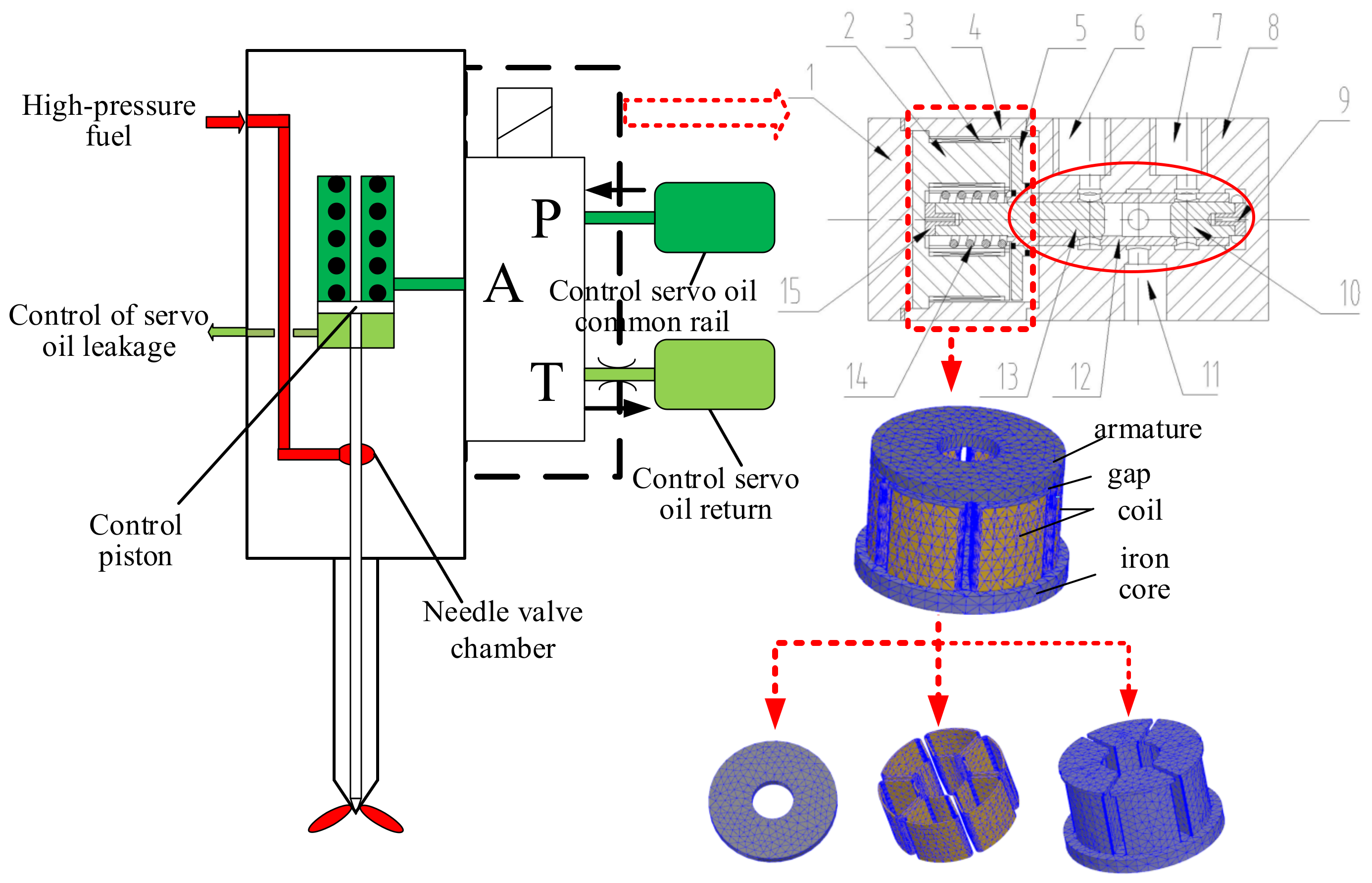
2. Structure and Principle of AMPSV and Test Bench

2.1. Structure and Principle of AMPSV

Using a marine, low-speed, small cylinder diameter, two-stroke diesel engine, common rail type, electronically controlled injection system as the application object, the solenoid valve design for the injection control of an electronically controlled hydro-boost injector, the principle is shown in Figure 1. In the case where the solenoid valve is installed on the injector, control hole A is connected to the injector control chamber. In the case where the solenoid valve is de-energized, the control servo oil is connected to control port A through the solenoid valve P port. In the case where the needle valve control chamber is at high pressure, the needle valve is closed under the control chamber pressure and spring pre-pressure. In the case where the solenoid valve is energized, the solenoid valve spool moves, the control port A is connected to the return port T, the needle valve control chamber pressure drops, and the needle valve is under the high-pressure fuel in the needle valve chamber. The needle valve is lifted under the action of high-pressure fuel in the needle valve cavity to achieve fuel Injection.
In the upper right corner of Figure 1 is a structure of AMPSV. Its working principle is that the armature and the outer spool are laser-welded into a whole, forming the solenoid valve motion parts. In the case where the solenoid valve is not energized (in the initial state), there is no electromagnetic suction, and the outer valve core fits closely with the proper inner cone valve core under the action of the reset spring. The return oil inlet is not connected with the control port, while the control port is connected with the oil inlet port. At this time, the oil pressure of the oil inlet is equal to the oil pressure of the control inlet. As shown in Figure 2a, with the solenoid valve energized, the armature and the outer valve core will move to the left of the reset spring under the electromagnetic suction until the outer core inlet seat, and the left cone is pressed. Figure 3 shows Annular pole electromagnet and moving parts.

2.2. Test Bench

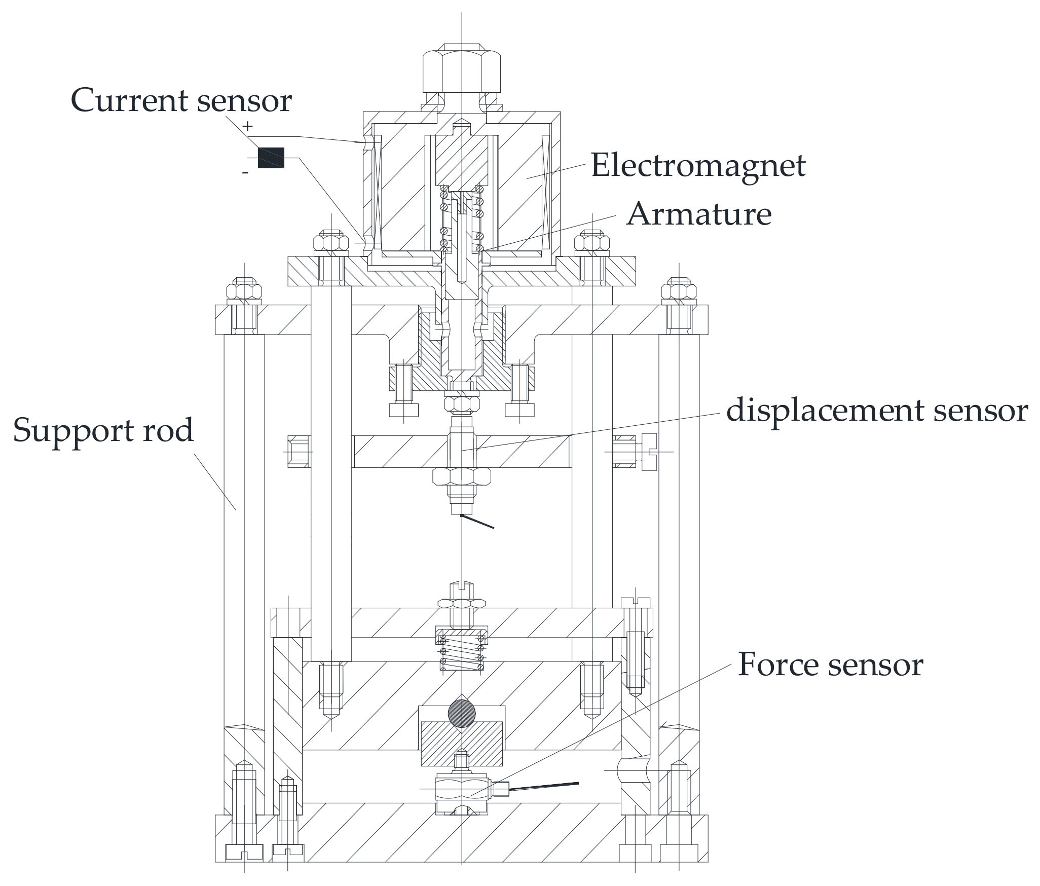
2.2.1. Static Electromagnetic Force Testing Device

The static electromagnetic force test setup is shown in Figure 4, where the parameters of the sensors used are shown in Table 1.
Test principle of the test stand
Testing principle of excitation current
The current signal can be measured by passing one end of the solenoid coil wire through the current sensor.
The principle of the armature displacement test
The distance between the electromagnet and the armature is regulated and tested by means of fine-tooth threads and high-precision displacement sensors.
Static electromagnetic force test principle
The static electromagnetic force is transmitted to the force transducer through the bracket, and the force sensor tests the magnitude of the electromagnetic force.

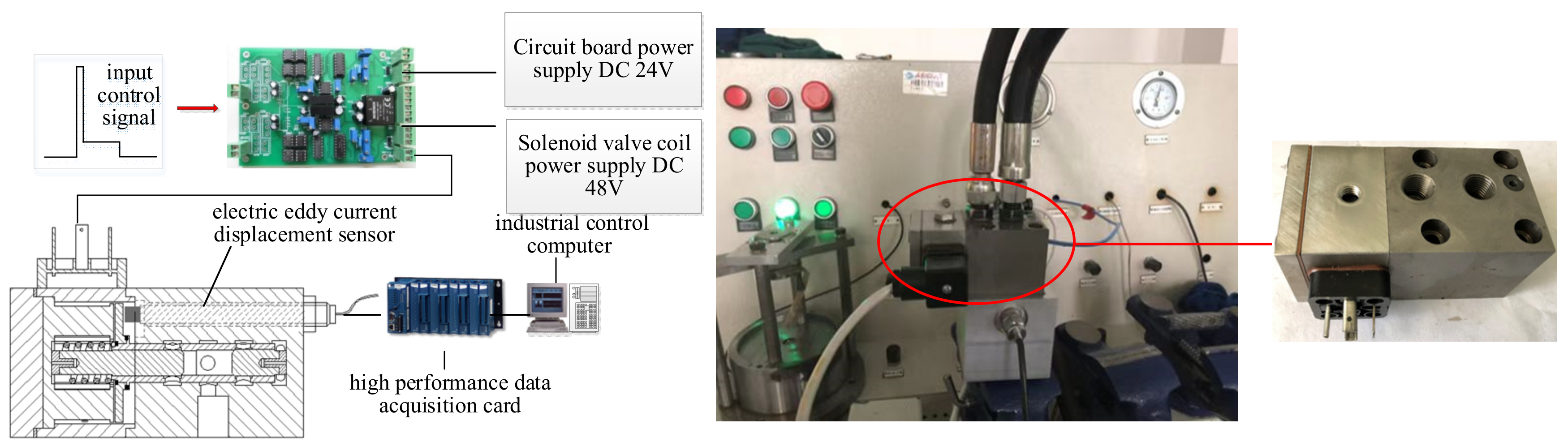
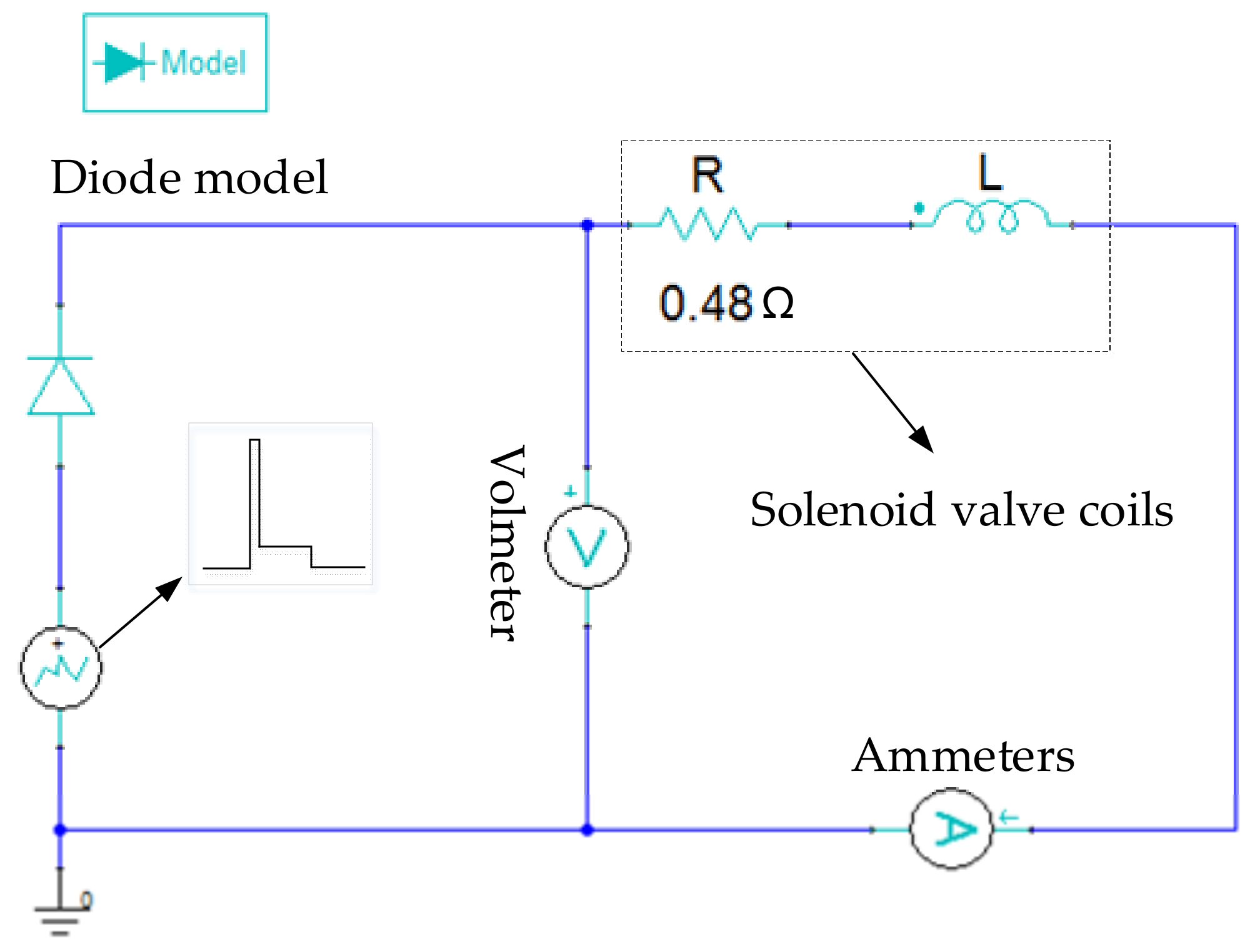
2.2.2. Solenoid Valve Dynamic Characteristics Test Bench

With a high-speed high-flow solenoid valve as the test object, the solenoid valve test table structure is shown in Figure 5. The whole test bench includes a high-speed high-flow solenoid valve, drive circuit, high-performance data acquisition card (NI-PCI-7851R) and industrial control computer, etc. IPC sends the input control signal to the drive circuit. The drive circuit is converted to a corresponding set current signal according to the control voltage signal.
The current sampling part collects the current signal of the output circuit, compares the collected current signal and the set current signal, enlarges the error between the two signals through the hardware PID control process, and the amplified error signal is given to the voltage pulse control chip (TL494). In the case where there is an error between the two, the chip will change the output voltage duty cycle to change the output current, until the error between the two reaches the set error, so that the output current signal can be controlled by setting the current signal. After lowering the action of the solenoid valve coil, the solenoid valve is fully open to maintain the solenoid valve open state. In the case where the solenoid valve needs to be reset, the output current signal is directly reduced to 0 A, and the solenoid valve is reset under the action of the spring force. During the operation of the solenoid valve, monitor the armature displacement of the armature with the eddy current displacement sensor installed on the valve body, and transmit the armature displacement signal to the industrial control computer, for display and data preservation. Because the solenoid valve moves fast, the CZ600 type of electric eddy current displacement sensor with a high response frequency is selected to measure the armature of the solenoid valve displacement signal. The maximum response frequency is 10 kHz, the linear range is 0.30~1.36 mm, and the measurement error is not more than 1.00%.

3. Finite Element Model and Validation

3.1. Mathematical Model

Figure 1, the moving parts are subject to the electromagnetic suction force, the spring pretension force and the friction force, respectively, and their resultant force is:
F = F s F m F f F 1
The maximum displacement of the outer spool is 0.32 mm, the spring stiffness is 80.0 N/mm, and the pretension force of the reset spring is 150 N. Because the external valve spool works in the servo hydraulic oil, its lubrication conditions are good, the damping k is set to 20 N/(m·s−1), the friction of the movement process F = kv. Because the left and right cone spool are equal in diameter, the left and right fluid pressure of the external spool are offset. The hydraulic oil contacted by the armature is the solenoid valve leakage hydraulic oil, and the pressure P is 0.20 MPa. Because the right-side area of the armature is greater than the area of the left side area, the left and right force areas of the moving parts are SL and SR, respectively. Because the left and right areas of the armature are equal, the actual action area of the moving parts is the ring area of the blue shadow part in Figure 6.
The armature is forced to the right by the pressure of the mixture. Because the armature hole is the through hole, the area difference behind the front of the armature is not affected during the movement process of the solenoid valve.
F 1 = F R F L = ( S R S L ) · p = π ( 13 2 10 2 ) 4 × 0.2 = 10.8 ( N )
According to the structural characteristics of this electromagnet, its working magnetic circuit is mainly composed of an electromagnetic core, an air gap (including working gap, residual gap) and an armature. The designed electromagnetic magnetic induction strength is between 7000 and 12,000 Gs, the magnetic permeability of soft magnetic materials such as DT4C is more than 10,000 times that of air permeability, and the magnetic resistance of the iron core is very small compared with the air gap of the same geometric size. The magnetic resistance is mainly concentrated in the air gap.
The reluctance of the magnetic path is:
R m R δ = l μ 0 · S = 2 δ μ 0 · S
μ0 is the air magnetic conductivity at 1.25 × 10⁻⁶ H/m. According to Equation (3), the size of the magnetic resistance (air gap magnetic resistance) of the magnetic circuit is inversely proportional to the cross-sectional area of the magnetic circuit, and is directly proportional to the length of the magnetic circuit (the air gap width of the electromagnet is δ). When the electromagnetic magnetic field is not saturated, the air gap magneto resistance is the main part of the electromagnetic magnetic resistance.
The electromagnetic force equation is shown below:
F m = Φ 2 2 μ 0 · S = ( Ι · N ) 2 2 μ 0 · S · R m 2 = μ 0 · S · ( Ι · N ) 2 8 δ 2
If the magnetoresistance of conductive magnets such as the static iron core and armature is ignored, it is known from Equation (4) that the electromagnetic suction is inversely proportional to the square of the air gap width δ. As the air gap width increases, the electromagnetic suction will decrease rapidly. At the same time, with the increase in the air gap width δ, the electromagnetic ferromagnetic road magnetic leakage will also increase, further reducing the electromagnetic suction.
When the solenoid valve is on
F m F s k v F 1 = m d 2 x d t o p e n 2
t o p e n = m F m F s kv F 1 d 2 x
When the solenoid valve is closed
F s F m k v F 1 = m d 2 x d t c l o s e d 2
t close = m F s F m kv F 1 d 2 x
From Equations (5) and (6), the opening and closing time of the solenoid valve stroke is related to the moving armature mass, the electromagnetic suction, the reset spring pretension force and the motion resistance.
F1 = 10.8 N, Fs = 150 N, ((since the external spool operates in the servo hydraulic oil, the damping k is set to 20 N/(m·s−1))) From the (6) and (8) Equation, topen and tclosed are inversely proportional to Fs, and are directly proportional to m. It can be concluded that the opening and closing time can be reduced by reducing the armature mass or increasing the electromagnetic force, but the electromagnetic suction has a certain relationship between the iron mass and the armature, so it is necessary to explore the specific relationship between the electromagnetic force and the armature mass so as to change the armature mass reasonably.

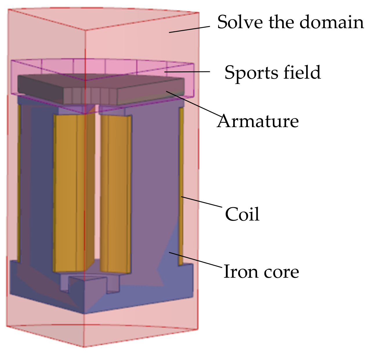
3.2. Finite Element Model and Basic Settings

The ANSYS Maxwell software simulates the action of the solenoid valve and establishes a three-dimensional finite element model of the solenoid valve as shown in Figure 7. The excitation of the coil is provided by an external circuit, as shown in Figure 8.

3.2.1. Define the Material Properties and Movement Settings

DT4C is a ferromagnetic material; its BH curve is shown in [24] and its saturation magnetic induction intensity is about 1.6~1.7 T. Specifically, μ is the absolute permeability of the DT4C material, and μ 1 is the permeability of the vacuum, at a value of 4π × 10−7 H/m.
The material of the coil is set as copper, the relative permeability is set to 1, the conductivity is 5.71 s/m; the static core and armature materials are set as electrical pure iron, the conductivity is 1107 s/m; the armature region material is hydraulic oil, the relative permeability is 1; the solution domain is set to air, and the relative permeability is 1.
The armature movement is set as a straight movement along the negative direction of the Z axis, the working air gap is 0.42 mm, the residual air gap is 0.10 mm, the mass of the armature is 26.00 g, the movement stroke is 0.32 mm, in addition, the total mass of the external valve core should be 56 g. The spring pretension force received when the solenoid valve is not opened is 150.00 N, and the damping k is set to 20.00 N/(m∙s−1).

3.2.2. Boundary Conditions, Incentive Source, Grid Section and Solution Setting

Considering the eddy current effect of armature and static iron core, set the coil turns of a single pole to 20 to create a coil containing the coil winding excitation source. The coil excitation is provided by an external circuit, as shown in Figure 8.
Internal grid dissection was used to set the maximum grid size of the armature, static core and coil as 3.60 mm, 4.2 mm for the motion domain, and 8.00 mm for the solution domain. The final total number of grids obtained is 98,445.
With a 3D transient electromagnetic field solver, the simulation steps were set to 0.1 ms and 16 ms, respectively, and the solution results of each substep were recorded.

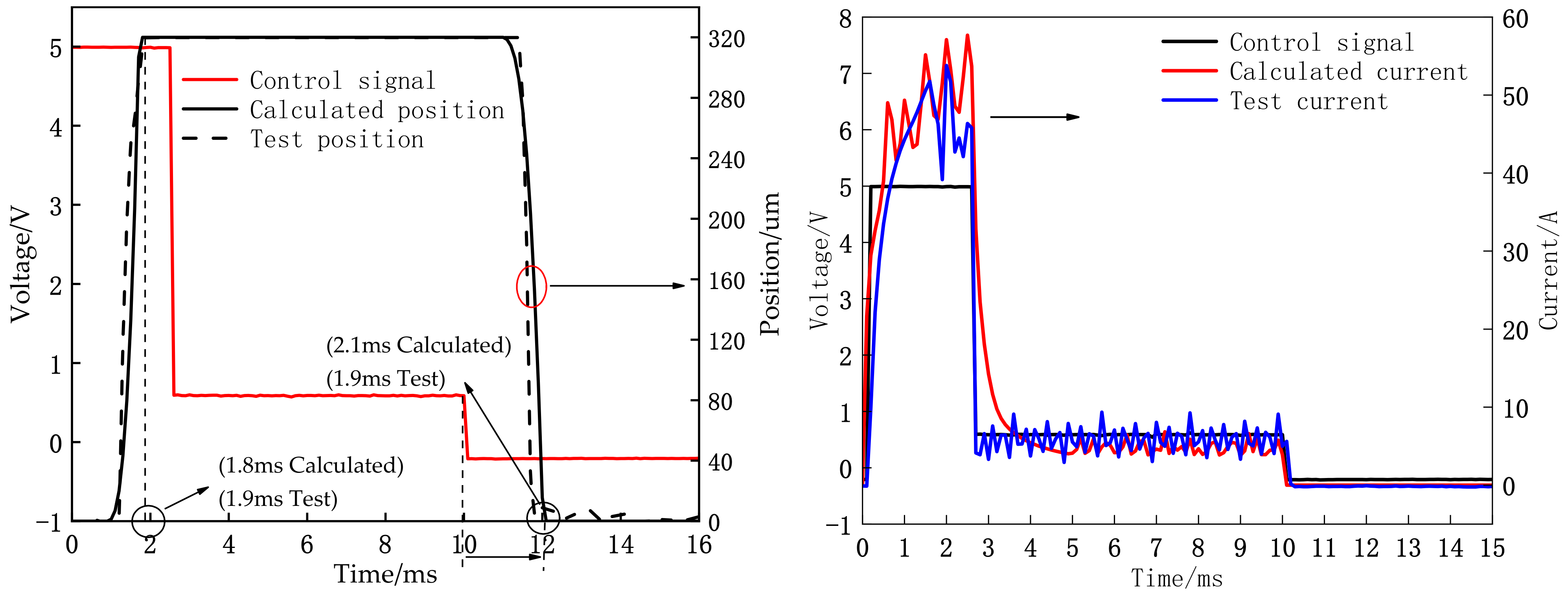
3.3. Model Test Validation

As can be seen from Figure 9, in the solenoid valve spool opening (i.e., armature working air gap) 0.20~0.35 mm range, the maximum deviation of the static electromagnetic suction force of the solenoid occurs in the 18~34 A current interval. The actual excitation current of the solenoid valve is closed-loop control; its excitation current control target is a peak current in the range of 45~50 A, and a maintenance current in the range of 4.0~6.0 A. The 18~34 A current range is located in the transition area of the sudden change of the excitation current from peak current to maintenance current, which has less influence on the solenoid valve control; the model deviation is small in the range of peak current and maintenance current, the maximum deviation is 5.0%, and its error is within the range allowed by the project.
Figure 10 shows the comparison of the passing test and the calculation results. The measured opening response time of the solenoid valve is 1.9 ms, the calculated value is 1.8 ms, the error is 5%; the closing response time is 1.9 ms, the calculated value is 2.1 ms, and the error is 9.5%. The error is due to the difference between the calculation circuit and the actual driving circuit, the response speed is faster and the circuit delay is shorter. The trend of the solenoid valve can verify the accuracy of the model.

4. Effect of Armature Punching on Dynamic Response of Solenoid Valve and Electromagnetic Force

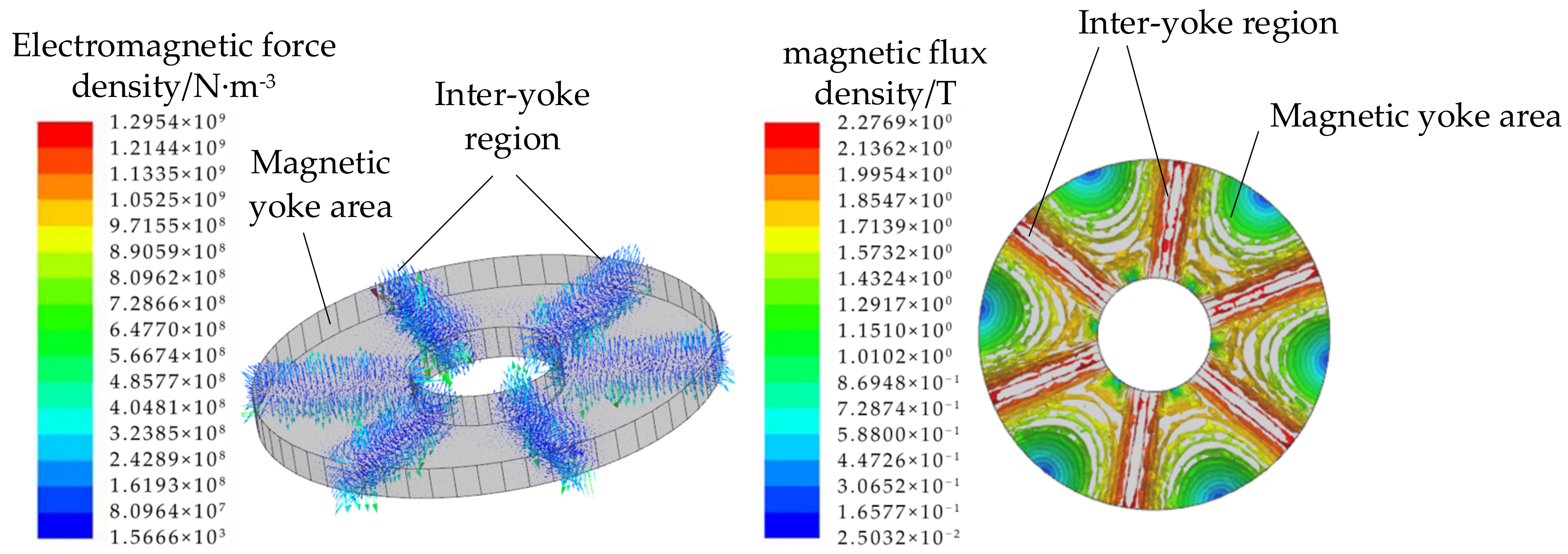
4.1. Explore the Distribution Law of Armature and Electromagnetic Force

According to the model calculation, the armature model has a great influence on the electromagnetic force and the response time of armature, and further solves the 3D simulation of the instantaneous electromagnetic field of the solenoid valve with ANSYS Maxwell simulation software. In order to simplify the model and improve the calculation efficiency, considering that the ring electromagnetic magnetic loop mainly consists of static iron core, coil and armature. The model removes the external valve core. At the same time, considering that the magnetic circuit and structure are axial symmetry, the calculation results of the solenoid valve 1/6 model shown in Figure 11 are compared with the whole model. The opening response is consistent, although the closing response difference is 4.8%. This error was caused by the fact that the grid number of the full model was 98,445 and the change to the 1/6 model resulted in a grid number of 16,535, not 1/6 of the full model. This error is small and the calculation time is reduced from 5 h 34 min to 36 min, which can meet the accuracy requirement of the analysis and calculation. Subsequently, the 1/6 model is used to carry out the design research of the solenoid valve armature. According to the model calculation, the armature motion of the solenoid valve at the t = 2.0 ms moment is dense in the inter-yoke area and sparse in the magnetic yoke area. Similarly, the electromagnetic force is mostly distributed in the inter-yoke area of the armature, but less in the magnetic yoke area.
Figure 12 shows the armature magnetic induction strength and the electromagnetic force distribution at t = 2.0 ms. In fact, the same law is in force in other moments of the solenoid valve, indicating that the contribution of each part of the armature to the electromagnetic force is different, and very different, for the optimization design of the armature structure behind provides ideas.

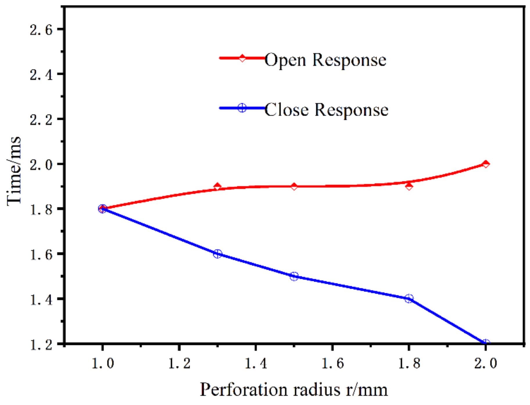
4.2. Effect of Armature Punching on the Response Time of the Solenoid Valve

Figure 13 shows the static electromagnetic force distribution. The main contribution of the static electromagnetic force is in the central region of the armature of the magnetic yoke area, while the inter-yoke area contributes less to the static electromagnetic force.
Figure 14 shows the two punching schemes. Figure 14a shows the magnetic yoke area punching, and Figure 14b shows the inter-yoke area punching. The parameter variable for the punch is the hole radius r0.
The centre distance from the centre of the armature is h0, the opening response time of the solenoid is topen, and the closing response time of the solenoid is tclosed. The relationship between the punching radius and position of the yoke area and the dynamic response of the solenoid valve is shown in Table 2.
Concerning the relationship between the punching radius and the mass of the moving part armature, the w value is the reduced mass fraction of the moving part (i.e., the armature plus the external valve core) after drilling. Through the calculation of the armature hole’s diameter and punching position, as shown in Table 2, the punching in the yoke zone has no effect on the dynamic response of the solenoid valve. In the magnetic yoke interval area, the aperture of the hole has a great influence on the dynamic response of the solenoid valve. As the punch diameter increases, the solenoid opening response time increases and the closing response time decreases. For the same aperture, the punching position has basically no effect on the solenoid valve opening/closing response, as shown in Figure 15. The colour of the bubbles in this diagram represents topen. The size of the bubbles represents tclosed.
In particular, when h0 = 13 mm, the solenoid closing response time decreased 33.3% compared to the open, while the opening response increased by only 11.7% and the overall response time decreased by 13.2%, as shown in Figure 16.

5. Armature Design Scheme and Optimization

5.1. Armature Design Scheme

Based on the punching of Figure 14, further design of the two slotting schemes is performed as shown in Figure 17. A trapezoidal groove is opened in each of the six yoke regions of the armature to form the slot scheme A—trapezoidal groove of Figure 17a. The r1 and r2 are the outer and inner radius of armature in mm. L4, L5 are upper and bottom lengths of trapezoidal grooves in mm. L0, L1, L2 are described in Figure 17a in mm. A similar fan-shaped slot is opened in each of the six yoke regions of the armature to form the slot scheme B on Figure 17b. The r3 is the radius of the armature annular outer circle in mm after the grooving. The description of L3 is shown in Figure 15b, all in mm. Other parameters are the same as in Scheme A.
Scheme A The relationship between the armature mass m and the parameters of the trapezoidal groove is:
m A = s A × h 0 × ρ
s A = s 0 s 1
s 0 = π ( r 1 2 r 2 2 )
s 1 = 6 × 1 2 × ( L 3 + L 4 ) × ( r 1 L 0 L 1 )
L 4 = 2 L 0 4 L 1 11.2 3 + r 1
L 5 = r 2 4 L 1 + 2 L 2 3
where mA is the mass of armature in g; h0 is the thickness of armature in mm; ρ is the density of armature material is 7.87 × 10⁻³ g·mm−3; SA, S0, and S1 are the cross-sectional area of the armature after slotting, cross-sectional area of the armature before slotting, and cross-sectional area of the six trapezoidal grooves in mm2, respectively.

5.2. Comparison of the Two Slotting Schemes and the Armature Structure Optimization

Through simulation calculation, it has been found that the solenoid valve dynamic response of Scheme B is generally better than that of Scheme A. The armature structure is optimized with scheme B as the slotted scheme below. The thee targets of parameter optimization are the solenoid valve opening response time(topen), the closing response time(tclosed), and the electromagnetic force size (F5ms) at the closing time of the control signal. The mass of the armature is closely related to the geometry of the armature. Due to structural constraints, the outer and inner circle radii r1 and r2 have been determined. The armature thickness h0, the sector slot geometry parameter L3, and r3 are selected as the three parameters to be optimized for optimization. To select the range of armature thickness, the relationship between different armature thicknesses and the solenoid valve dynamic response was calculated as shown in Figure 18. The thickness of the armature is less than 2.6 mm and the opening response is 1.9 ms; once it is greater than or equal to 2.6 mm, the opening response speed of the solenoid valve is increased, and the closing response time will extend with the increase in the armature thickness. Considering that the armature opening will increase the magnetic circuit magnetic resistance, it is possible to reduce the opening response speed of the solenoid valve, and the calculated armature thickness is selected as [2.6, 3.0].
In order to select the parameter range of the armature fan groove, the relationship between the slotted parameters L3, r3 and the dynamic response of the solenoid valve is calculated by parametrization, as shown in Table 3.
It is found that when L3 is certain, the opening response time of the solenoid valve decreases first and then increases with the increase in r3. The solenoid valve closing response time tends to increase with the increase in r3. When r3 is certain and a small value, such as 10 mm, the solenoid opening response time is short with the increase in L3. However, when r3 is greater than 10 mm, the solenoid opening response time hardly changes with the increase in L3. In terms of the closing response, when r3 is certain, the opening response time of the solenoid valve increases with the increase in L3, but this trend decreases as r3 increases. The parameter range of the open fan groove is selected by the above rule, as shown in Table 4.
Use the optimization function of Maxwell, set the value range of parameters. Solve the optimal solution of multiple objectives by optimizing the objective function Equations (15)–(17). Sequential Non-Linear Programming (SNLP) is used to optimize the parameters to place the target close to the set point. It approximately characterizes the FEM analysis results using the response surface. Rapid optimization is achieved by approximation and mild evaluation of the cost function. By calculating the function ‘X At Y Val’, the ‘Y At X Val’ function defines the time range, conditions, target and target weights, as shown in Table 5.
t o p e n = X A t Y V a l ( a b s ( P o s i t i o n ) , 0.32 m m )
t c l o s e d = X A t Y V a l ( a b s ( P o s i t i o n ) , 0 ) 0.005 s
F 5 m s = Y A t X V a l ( a b s ( F o r c e _ z ) , 0.005 s )
The function X At Y Val (abs(Position), 0.32 mm) indicates a time value when the absolute value of the armature displacement is at 0.32 mm. To speed up the solution, with an empirically selected time range of 0 to 3 ms, the function of t closed represents a time value returned by the armature displacement at 0 mm. The difference lies in the time range selected by X because the reset of the armature is made after the solenoid valve control model is closed, so the 5 ms given by the control signal needs to be reduced after the solution. Furthermore, in order to ensure that the solenoid valve can remain open until the control signal is cut off, the F5ms can be greater than the solenoid valve needs to maintain the open minimum electromagnetic force of 177 N.
Y At X Val (abs(Force_z), 0.005 s) indicates the current electromagnetic force of the solenoid valve when the control signal is cut off at 0.005 s.
After 55 iterations, a better solution was selected, as shown in Table 6 for the optimized armature structure parameters. After the optimization, the armature has reduced the weight of 12.1 g. After optimization, the opening response time of the solenoid valve is reduced by 11.1%. The closing response time is reduced by 30%, and the electromagnetic force drops by 1.0% when the control signal is closed, but it is still greater than the minimum electromagnetic force of 177 N for keeping the solenoid valve open, as shown in Table 7.

6. Analysis and Discussion

According to the previous calculation and analysis, the magnetic path of the annular electromagnet is mainly distributed in the inter-yoke region of the armature, but a few parts are also distributed in the yoke region of the armature. The slot in the magnetic yoke area is bound to increase the magnetic resistance of the magnetic path, causing the increase in the electromagnetic force to slow down, thus leading to the increase in the opening response time of the solenoid valve, but the reduction in the armature mass will improve the opening response speed of the solenoid valve. After the slot, it is difficult to determine whether the opening response time of the solenoid valve is increased or reduced. In terms of the closing response, because the control signal is closed, the armature slot increases the magnetic resistance of the magnetic road and causes the electromagnetic force to decrease the speeding up. In addition, the quality of the moving parts decreases after the armature slot, and the closing response time of the solenoid valve will be reduced.
In order to analyze the mechanism of the improvement of the solenoid valve, a comparative analysis of three groups was conducted. The characteristics of the groups are shown in Table 8
The first group is compared between A and B. A comparison of electromagnetic force and armature displacement before and after optimization is shown in Figure 19. After the armature slot was found, the electromagnetic force curves of A and B basically coincide before 1 ms. There are two reasons: first, the distribution of the magnetic path in the armature is mainly concentrated in the inter-yoke area, and the magnetic yoke slot area has less influence on the magnetic path. Second, for the slotted part, the magnetic line will bypass the slotted part to the nearby unslotted part, and the magnetic induction strength is stronger than the unopened part near the slotted part. Comparison of the distribution map of the magnetic induction before and after optimization is displayed in the following figure.
At t = 1.0 ms, the armature magnetic induction strength is distributed, and after 1.0 ms, the electromagnetic force tends to slow down, which is because the armature is already saturated in parts of the inter-yoke area as shown in the DT4CB-H curve of the armature material of Figure 20.
In the case where the strength of the applied magnetic field is increased, the intensity of magnetization of the armature increases slowly as shown in Figure 20—Comparison of electromagnetic force and armature displacement before and after optimization. The maximum electromagnetic force appears at 2.0 ms, but the maximum electromagnetic force after the slot is 463.8 N, greater than the maximum electromagnetic force of the solenoid valve outside the slot. The reason is that after the solenoid valve is opened, the loss of static iron core vortex increases as the current rises. At t = 2.0 ms, the loss of static iron core is 307.0 W, while the loss of unslotted static iron core is 355.0 W, the iron loss decreases, the rate of energy conversion increases, and the force of maximum electromagnetic increases. As for the shorter opening response time of Scheme B when compared to Scheme A, the main reason is that the mass of the motion parts in Scheme B decreases more, so the armature motion t2 time is shorter, decreasing from 1.0 ms to 0.8 ms. Figure 21 shows the solenoid valve response time of the comparison group. A_topen and A_tclosed respectively indicates the open and close response times of solenoid for solution A. B_topen and B_tclosed respectively indicate the open and close response times of solenoid for solution B. C_topen and C_tclosed respectively indicate the open and close response times of solenoid for solution C. From the comparison of A and C, the opening preparation time is the same, and the reduction of the armature movement time indicates that the armature slot will increase the magnetic resistance and lead to the slower growth rate of the electromagnetic force.
Combined with A and C, the opening response time of both solenoid valves is 1.8 ms, which indicates that the increased opening response time of the solenoid valve caused by the armature slot is offset by the reduced starting response time of the solenoid valve caused by the weight loss of armature slot motion parts. It is worth noting that after the armature slot, the intensity distribution of armature magnetic induction appears stronger near the slot than before the slot, which is also one of the reasons why the increase in the offset magnetic resistance causes the slower opening response speed of the solenoid valve. The dynamic response of the solenoid valve is analyzed from the perspective of mass loss after armature opening. The comparative analysis of the third group, that is, between scheme B and C, in the preparation reduction time of the solenoid valve is t3. The armature preparation reduction time of scheme B is 0.2 ms less than that of C. The main reason is the increase of magnetic resistance brought after slotting, which accelerates the reduction speed of electromagnetic force. In terms of the armature reset movement time t4, the reset movement time of the armature of scheme B is 0.4 ms less than that of C as shown in Figure 21. The reason is that the increase of the magnetic resistance brought after opening the slot accelerates the superimposed effect of the reduction speed of the electromagnetic force and the mass reduction of the moving parts.

7. Conclusions

This study investigates and validates the electromagnetic force distribution law on the APSV’s armature. Following a comparison and analysis of the two programs and the usage of the electromagnetic force distribution law that was suggested to them, the following conclusions can be drawn:
(1)
The circular multipole column solenoid is present during the armature’s motion; the distribution of magnetic density and magnetic force shows a dense distribution in the inter-yoke area and a sparse distribution in the magnetic yoke region.
(2)
Punching in the armature yoke zone has basically no effect on the dynamic response of the solenoid valve.
(3)
Whether it is punched in the magnetic yoke area or the inter-yoke area, with a certain punching radius, the distance between the hole center and the armature center has less impact on the response of the solenoid valve.
(4)
When punching in the inter-yoke yoke area, the punching aperture has a large impact on the dynamic response of the solenoid valve. With the increase in the punching diameter, the response time of the solenoid valve opening increases, but its increase is not large. The closing response time is shortened, and the shortening range is large. Without changing the circuit and other structural parameters, Solution B is better than solution A.
During the opening stage of the solenoid valve, the weight reduction of the armature and the accelerated magnetization speed in part of the armature can offset the adverse impact of the increased magnetic resistance brought by the armature slot on the opening response of the solenoid valve, and even reduce the opening response time of the solenoid valve. During the closing stage of the solenoid valve, the slot of the armature increases the magnetic resistance, which can speed up the decline speed of the electromagnetic force, and the weight loss of the solenoid valve motion brought by the solenoid slot will reduce the closing response time of the high-speed solenoid valve. After optimization, the weight of the moving parts is reduced by 21.6%, the opening response time of the solenoid valve is reduced by 11.1%, and the closing response time is reduced by 30.0%, which reduces the oil film damping of the armature motion and also improves the overall dynamic response characteristics of the solenoid valve.

Author Contributions

Conceptualization, Y.F.; methodology, Y.F.; software, Y.F. and H.W.; validation, Y.F., H.W. and L.X.; formal analysis, Y.F.; investigation, Y.F.; resources, J.Y.; data curation, Y.F.; writing—original draft preparation, Y.F. and H.W.; writing—review and editing, N.H. and J.Y. All authors have read and agreed to the published version of the manuscript.

Funding

This work was funded by the National Natural Science Foundation of China (Grant No: 52271328).

Data Availability Statement

Not applicable.

Acknowledgments

I would first like to thank my supervisor, Jianguo Yang, whose expertise was invaluable in formulating the research questions and methodology. Your insightful feedback pushed me to sharpen my thinking and brought my work to a higher level. I also want to thank my master’s supervisor, Yuhai He, who led me into the research field of solenoid valves.

Conflicts of Interest

The authors declare no conflict of interest.

Nomenclature

F The combined force on the moving parts (N)r0Perforation radius (mm)
FsResetting spring force of the resetting spring (N)r1, r2Radius of outer and inner circle of armature (mm)
FmElectromagnetic suction force (N)r3Radius of the outer circle of the ring after slotting of the armature (mm)
FfFriction force on the outer spool (N)RmMagnetic circuit reluctance (A/Wb)
F1Hydraulic pressure on the moving parts (N)RδAir gap reluctance (A/Wb)
FL, FRHydraulic pressure on the left and right sides of the moving parts (N)SMagnetic circuit cross-sectional area (mm2)
SLHydraulic pressure area on the left side of the moving parts (mm2)SRHydraulic pressure area on the right sides of the moving parts (mm2)
kDamping factor (N/(m·s−1))S1Cross-sectional area of 6 trapezoidal slots (mm2)
vInstantaneous speed of the moving parts of the solenoid valve (mm/s)S0, SACross-sectional area of armature before and after slotting (mm2)
h0Distance of the centre of the hole from the centre of the armature (mm)wMass fraction reduced by moving parts after perforation (%)
I Coil current (A)ΦMagnetic flux of magnetic circuit (Wb)
LMaximum displacement of armature movement (mm)μ0Air Magnetic Permeability (H/m)
lLength of magnetic circuit (mm)μ1Magnetic permeability of vacuum (H/m)
L3, L4Length of the upper and lower bottom of the trapezoidal slot (mm)μAbsolute permeability of DT4C material
NNumber of turns of coilρDensity of armature material (g·mm−3)
AMPSVannular multi-pole solenoid valveF5msThe magnitude of the electromagnetic force at the moment the control signal is turned off (N)
topenOpen response time (ms)tclosedClose response time (ms)

References

  1. Li, H.; Shi, L.; Deng, K. Development of turbocharging system for diesel engines of power generation application at different altitudes. J. Energy Inst. 2016, 89, 755–765. [Google Scholar] [CrossRef]
  2. Han, Y.; Zhang, L.; Tian, J. Investigation of transient deterioration mechanism and improved method for turbocharged diesel engine. Energy 2016, 116 Pt 1, 250–264. [Google Scholar] [CrossRef]
  3. Park, J.; Choi, J. Optimization of dual-loop exhaust gas recirculation splitting for a light-duty diesel engine with model-based control. Appl. Energy 2016, 181, 268–277. [Google Scholar] [CrossRef]
  4. Thangaraja, J.; Kannan, C. Effect of exhaust gas recirculation on advanced diesel combustion and alternate fuels—A review. Appl. Energy 2016, 180, 169–184. [Google Scholar] [CrossRef]
  5. Park, S.W. Optimization of combustion chamber geometry for stoichiometric diesel combustion using a micro genetic algorithm. Fuel Process. Technol. 2010, 91, 1742–1752. [Google Scholar] [CrossRef]
  6. Prasad, B.V.V.S.; Sharma, C.S.; Ravikrishna, R.V. High swirl-inducing piston bowls in small diesel engines for emission reduction. Appl. Energy 2011, 88, 2355–2367. [Google Scholar] [CrossRef]
  7. Su, L.; Li, X.; Liu, F. Numerical analysis on the combustion and emission characteristics of forced swirl combustion system for DI diesel engines. Energy Convers. Manag. 2014, 86, 20–27. [Google Scholar] [CrossRef]
  8. Zehni, A.; Saray, R.K.; Poorghasemi, K. Numerical comparison of PCCI combustion and emission of diesel and biodiesel fuels at low load conditions using 3D CFD models coupled with chemical kinetics. Appl. Therm. Eng. 2017, 110, 1483–1499. [Google Scholar] [CrossRef]
  9. Wang, Z.; Liu, H.; Reitz, R.D. Homogeneous charge compression ignition (HCCI) combustion of Polyoxy methylene dimethyl ethers (PODE). Fuel 2016, 183, 206–213. [Google Scholar] [CrossRef]
  10. Reitz, R.D.; Duraisamy, G. Review of high efficiency and clean Reactivity controlled compression ignition (RCCI) combustion in internal combustion engines. Prog. Energy Combust. Sci. 2015, 46, 12–71. [Google Scholar] [CrossRef] [Green Version]
  11. Woo, C.; Kook, S.; Hawkes, E.R. Effect of intake air temperature and common-rail pressure on ethanol combustion in a single-cylinder light-duty diesel engine. Fuel 2016, 180, 9–19. [Google Scholar] [CrossRef]
  12. Qiu, T.; Dai, H.; Li, X. Optimising the cam profile of an electronic unit pump for a heavy-duty diesel engine. Energy 2015, 83, 276–283. [Google Scholar] [CrossRef]
  13. Chen, P.; Wang, J. Air-fraction modeling for simultaneous Diesel engine NOx and PM emissions control during active DPF regenerations. Appl. Energy 2014, 122, 310–320. [Google Scholar] [CrossRef]
  14. Maiti, R.; Saha, R.; Watton, J. The static and dynamic characteristics of a pressure relief valve with a proportional solenoid-controlled pilot stage. Proc. Inst. Mech. Eng. Part I J. Syst. Control. Eng. 2002, 216, 143–156. [Google Scholar] [CrossRef]
  15. Tao, G.; Chen, H.Y.; He, Z.B. Optimal design of the magnetic field of a high-speed response solenoid valve. J. Mater. Process. Technol. 2002, 129, 555–558. [Google Scholar] [CrossRef]
  16. Topçu, E.E.; Yüksel, İ.; Kamış, Z. Development of electro-pneumatic fast switching valve and investigation of its characteristics. Mechatronics 2006, 16, 365–378. [Google Scholar] [CrossRef]
  17. Nitu, S.; Nitu, C.; Dumitrescu, G. Electromagnetic actuator with magnetic stored energy. J. Mater. Process. Technol. 2007, 181, 153–158. [Google Scholar] [CrossRef]
  18. Angadi, S.V.; Jackson, R.L.; Ham, J.K. Reliability and life study of hydraulic solenoid valve. Part 1: A multi-physics finite element model. Eng. Fail. Anal. 2009, 16, 874–887. [Google Scholar] [CrossRef]
  19. Angadi, S.V.; Jackson, R.L.; Bae, J. Reliability and life study of hydraulic solenoid valve. Part 2: Experimental study. Eng. Fail. Anal. 2009, 16, 944–963. [Google Scholar] [CrossRef]
  20. Liu, Q.; Bo, H.; Qin, B. Experimental study and numerical analysis on electromagnetic force of direct action solenoid valve. Nucl. Eng. Des. 2010, 240, 4031–4036. [Google Scholar] [CrossRef]
  21. Liu, Q.; Bo, H.; Qin, B. Design and analysis of direct action solenoid valve based on computational intelligence. Nucl. Eng. Des. 2010, 240, 28902896. [Google Scholar] [CrossRef]
  22. Liu, Q.; Bo, H.; Qin, B. Optimization of direct action solenoid valve based on CloudPSO. Ann. Nucl. Energy 2013, 53, 299–308. [Google Scholar] [CrossRef]
  23. Wang, L.; Li, G.; Sun, S. Effect of characteristic parameters on the magnetic properties of solenoid valve for high pressure common rail diesel engine. Energy Convers. Manag. 2016, 127, 656–666. [Google Scholar] [CrossRef]
  24. Sun, Z.; Li, G.; Wang, J. Effects of structure parameters on the static electromagnetic characteristics of solenoid valve for an electronic unit pump. Energy Convers. Manag. 2016, 113, 119–130. [Google Scholar] [CrossRef]
  25. Gao, H.; Fu, X.; Yang, H.; Tsukiji, T. Numerical and experimental investigation of cavitating flow in oil hydraulic ball valve. In Proceedings of the JFPS International Symposium on Fluid Power 2002; The Japan Fluid Power System Society: Tokyo, Japan, 2002; Volume 2002, pp. 923–928. [Google Scholar]
  26. Xia, S.H.; Zheng, J.B.; Hou, X.J. Cavitation analysis on ball valve in solenoid injector. Neiranji Xuebao/Trans. CSICE (Chin. Soc. Intern. Combust. Engines) 2012, 30, 354–358. [Google Scholar]
  27. Qiu, T.; Lei, Y.; Li, B. Flow characteristics of solenoid control valve during fuel stopping process for the unit pump. Neiranji Xuebao/Trans. CSICE (Chin. Soc. Intern. Combust. Engines) 2013, 31, 367–372. [Google Scholar]
  28. Qiu, T.; Dai, H.; Lai, M.C. Dynamic flow behavior during fuel-offloaded process in control valve for unit pump fuel system. Appl. Therm. Eng. 2016, 106, 153–160. [Google Scholar] [CrossRef]
  29. He, Y.H.; Yang, J.G.; Yu, Y.H.; Li, M.; Liu, C.Y.; Fan, Y.; Gao, J. High Speed High Flow Self–Reset Solenoid Valve. CN 2014101111355, 29 June 2016. [Google Scholar]
Figure 1. Injector structure diagram. 1—Valve cover; 2—Static core; 3—Valve housing; 4—coil; 5—Armature; 6—Oil inlet; 7—Oil return port; 8—valve body; 9—Right cushion block; 10—Right cone valve element; 11—Control port; 12—Outer valve core; 13—Left cone valve element; 14—Return spring; 15—Left cushion block.
Actuators 12 00054 g001
Figure 2. The structure of solenoid valve and solenoid valve in on and off working state. 1—Valve cover; 2—Static core; 3—Valve housing; 4—coil; 5—Armature; 6—Oil inlet; 7—Oil return port; 8—valve body; 9—Right cushion block; 10—Right cone valve element; 11—Control port; 12—Outer valve core; 13—Left cone valve element; 14—Return spring; 15—Left cushion block.
Actuators 12 00054 g002
Figure 3. Annular pole electromagnet and moving parts.
Actuators 12 00054 g003
Figure 4. The static electromagnetic force test stand.
Actuators 12 00054 g004
Figure 5. Solenoid valve test bench.
Actuators 12 00054 g005
Figure 6. Solenoid valve moving parts.
Actuators 12 00054 g006
Figure 7. Three-dimensional finite element model of the solenoid valve.
Actuators 12 00054 g007
Figure 8. The coil excitation adopts the external circuit.
Actuators 12 00054 g008
Figure 9. Comparison of simulated and experimental values of static electromagnetic suction force under different working air gaps.
Actuators 12 00054 g009
Figure 10. Comparison of calculated and experimental results.
Actuators 12 00054 g010
Figure 11. Electromagnet model.
Actuators 12 00054 g011
Figure 12. Armature magnetic induction strength and electromagnetic force distribution (t = 2.0 ms).
Actuators 12 00054 g012
Figure 13. Distribution of Static electromagnetic force.
Actuators 12 00054 g013
Figure 14. Punching scheme.
Actuators 12 00054 g014
Figure 15. Overall relationship of inter-yoke area perforation.
Actuators 12 00054 g015
Figure 16. The relationship between the bore size and the dynamic response of the solenoid valve.
Actuators 12 00054 g016
Figure 17. Slotting solutions for armatures.
Actuators 12 00054 g017
Figure 18. Effect of armature thickness h0 on the dynamic response of the solenoid valve.
Actuators 12 00054 g018
Figure 19. Comparison of electromagnetic force and armature displacement before and after optimization.
Actuators 12 00054 g019
Figure 20. Comparison of armature magnetic induction distribution clouds before and after optimization.
Actuators 12 00054 g020
Figure 21. Comparison group solenoid valve response time.
Actuators 12 00054 g021
Table 1. Sensor parameter.
Sensor NameSensor TypeMeasurement RangeSensitivityPrecision (%)Output Voltage (V)
Current SensorHall magnetic balance type 0~100 A0.1 V/A0.10~10
Displacement SensorsEddy current type0.36~1.36 mm8.99 V/mm0.10~10
Force SensorPiezoelectric type0~5.00 KN3.57 PC/N0.090~10
Table 2. Relationship between the drilling radius and position of the yoke area and the dynamic response of the solenoid valve.
r0/mmho/mmw/%topen/mstclosed/ms
0.012.00.001.72.1
1.010.00.891.82.1
1.012.00.891.82.1
1.014.00.891.82.1
1.015.00.891.82.1
1.310.01.411.82.1
1.312.01.411.82.1
1.314.01.411.82.1
1.315.01.411.82.1
1.510.01.791.92.1
1.512.01.791.82.1
1.514.01.791.82.1
1.515.01.791.82.1
1.812.02.551.82.0
1.814.02.551.82.1
1.815.02.551.82.1
2.012.03.041.82.0
2.014.03.041.82.1
2.016.03.041.82.1
Table 3. Relationship between slotting parameters and dynamic response of solenoid valve.
L3/mmr3/mmtopen/mstclosed/ms
2.08.0Can’t open——
2.010.02.10.9
2.014.01.61.4
2.018.01.61.9
3.010.02.01.1
3.014.01.61.6
3.018.01.61.9
4.010.01.91.2
4.014.01.61.8
4.018.01.61.9
5.010.01.91.5
5.014.01.61.9
5.018.01.61.9
Table 4. Parameter value range.
ParametersRange of Values
h0/mm2.6~3.0
L3/mm2.0~3.0
r3/mm12.0~15.0
Table 5. Properties of the solved target.
Calculated ItemsRangeConditionsObjectivesWeights
topten0~3 ms 1.5 ms40%
tclosed5~8 ms 1.5 ms40%
F5ms---177 N20%
Table 6. Comparison of parameters before and after optimization.
Parametersh0/mmL3/mmr3/mmm0/g
Before optimization2.80055.9
After optimization2.821443.8
Table 7. Target comparison before and after optimization.
Parameterstopen/mstclosed/msF5ms/N
Before optimization1.82261.5
After optimization1.61.4258.9
Table 8. Comparison of group characteristics.
Solutionsh0/mmSlotting Situationm0/g
A2.80 Trapezoidal slot49.00
B2.80 Scalloped slot43.80
C2.80 No Slot55.90
Disclaimer/Publisher’s Note: The statements, opinions and data contained in all publications are solely those of the individual author(s) and contributor(s) and not of MDPI and/or the editor(s). MDPI and/or the editor(s) disclaim responsibility for any injury to people or property resulting from any ideas, methods, instructions or products referred to in the content.

