Abstract
With technological advances and industrial upgrading, high-performance equipment has put higher demands on the performance of electro-mechanical actuators. With a view to making electro-mechanical actuators more reliable and integrated, firstly, an integrated electro-mechanical actuator module (IEMM) with multiple structural forms was proposed in this paper, and a comparative analysis was performed on the characteristics of different transmission schemes. Then, the feasibility of manufacturing the IEMM’s main bearing components using Carbon Fiber Reinforced Polymer (CFRP) with higher specific stiffness, specific modulus and specific strength was demonstrated by finite element simulation (FEA) software, in a bid to further reduce the weight of the IEMM. Next, a parameter estimation model, a heating power calculation model, and a thermal resistance calculation model were built, so that there is no need to rebuild the whole system model under different demand indexes. On this basis, a multi-objective optimization design model was built with light weight, low power loss, and high level of integration as optimization aims to achieve better comprehensive performance in the early design phase of the IEMM system. However, IEMM’s higher level of integration and its shell made of CFRP with a thermal conductivity of less than 5 W/m°C posed a challenge to the heat dissipation of the motor stator. Therefore, a thermal network model needs to be created in AMESim to evaluate the temperature of IEMM’s parts and components under different working conditions. Finally, the process of IEMM performance optimization design was described and improved, and performance optimization design was conducted by taking one of IEMM’s transmission schemes as an example.
1. Introduction
Electro-mechanical actuators have been widely applied in the mechanical industry and are evolving toward light weight, high reliability, low power loss, and a high level of integration. Researchers usually reduce the weight and power loss of electro-mechanical actuators and improve their reliability and level of integration through new materials, structures, and performance optimization design.
In terms of the structural integration design, based on modular concepts, German DLR’s laboratory studied the light-weight electro-mechanical actuator module controlled by torque, completed three times in iterations through more than ten years, and successfully integrated the brushless DC motor, harmonic gear drive and dual encoder into the module [1,2]. KUKA, also a German corporation, based on the previous results of DLR’s laboratory, integrated the driver, brake, torque sensor and angle sensor into the interior of the electro-mechanical actuator module [3]. Universal Robots, a Danish company, reduced the weight of the module with the Kollmorgen KBM series frameless motor and controlled the output torque through the current loop [4]. Kollmorgen, based in the United States, developed a dual closed-loop module by using a frameless motor as the driver and a dual photoelectric encoder for position feedback. The module has a compact structure and high kinematic accuracy. However, the axis of the module’s output end is non-collinear with that of the base [5]. South China University of Technology divided electro-mechanical actuator modules into general modules and special modules. General modules consist of type-I joints for rotational motion and type-T joints for swinging motion. Special modules are used for specific clamping, moving and fixing [6]. The Robotics Research Institute of Harbin Institute of Technology in China embedded the torque sensor into the compact electro-mechanical actuator module to improve the safety of force control [7]. Zhang et al. at the University of Saskatchewan present a study on the development of a novel two-degree-of-freedom piezoelectric rotary-linear actuator system; the system has extremely high motion accuracy and unlimited motion stroke, but its rated output speed is relatively small [8].
In terms of the performance optimization method, Bissal from KTH Royal Institute of Technology built a mechanical, electromagnetic and thermal multi-field coupling model for an ultra-high-speed electro-mechanical actuating system. Bissal also made a sensitivity analysis on the parameters such as the shape of the driver, size of the motor coil, and shell material, and conducted the system optimization design. However, the time for simulation and computing was long [9]. Persson from Linköping University optimized the design of three actuation schemes, i.e., mechanical, pneumatic and hydraulic schemes, for the balancing mechanism of industrial robots with dynamic characteristics, weight and volume as optimization objects. However, the model built by Persson did not delve into the coupling relationship between the parameters [10]. Mondol from the University of Saskatchewan adopted a dipar-and-conquer strategy, taking the natural frequency and weight of the frame as optimization objectives, to optimize the design of scaffoldings for CLS 2.0 quadrupole magnet, and the verification showed satisfactory results [11]. Han Xu from Beihang University, China presented an optimization design method for electro-hydrostatic actuators based on models. Through the establishment of the multidisciplinary design model covering dynamic characteristics, weight and thermal characteristics, Han achieved an electro-mechanical hydraulic control and thermal multidisciplinary coupling solution, which improved the efficiency of the optimization solution and saved design time and manpower cost [12].
The application of new materials is one of the important technical means to develop more lightweight equipment. Mitsubishi, a Japanese conglomerate, developed the PA10 manipulator, with its whole shell made of aluminum alloy. The ASIMO, the third generation of biped robots, developed by Honda, also a Japanese enterprise, adopted magnesium alloy for its shell. MER IDD, an end effector equipped by the United States on the Mars probe used titanium alloy for its motion joint shell. All these applications achieved a reduction in system weight without degrading the performance [13,14,15]. With the development of new materials, composite materials have drawn much attention from researchers and have been widely used in areas such as aerospace, medical devices, and sporting goods. Research shows that the application of advanced composite materials to aerospace structures can effectively reduce their weight by 20–30%, Combined with an optimized lay-up method, the application of CFRP to the manipulator’s arm can reduce the manipulator’s weight by more than 50% [16,17,18]. At present, manipulator’s arms made of CFRP have been applied in areas such as space manipulators and robot arms. German DLR’s laboratory [19] and Kinova [20], a Canadian robotics company, successfully applied composite materials to the manipulator’s arm and the end effector, respectively, to reduce the weight of the system. Besides the selection of composite materials and the structural design, some researchers also conducted research on material modification and preparation. On the other hand, additive manufacturing methods have been introduced for robot actuators to further reduce the weight [21].
To further improve the comprehensive performance of the electro-mechanical actuator module, enhance its reliability and level of integration, and reduce its weight and power loss, multiple integrated design schemes and parameter calculation methods are presented in this paper, and optimization design was conducted on these schemes through the multidisciplinary and multi-objective optimization design method and advanced composite materials. In Section 2, different structural forms and characteristics of IEMM are introduced. In Section 3, the performance and characteristics of CFRP are analyzed. IEMM’s parameter estimation and calculation models as well as the multidisciplinary and multi-objective optimization design calculation model are built in Section 4 and Section 5, respectively. The process of IEMM performance optimization design is proposed in Section 6. In Section 7, performance optimization design is conducted by taking one of IEMM’s transmission schemes as an example.
2. Transmission Schemes of Integrated Electro-Mechanical Actuator Module (IEMM)
The IEMM with multiple structural forms provided in this paper has the advantages of light weight, high reliability, and high level of integration. According to the output motion mode, specific integration scheme, and the presence of the reducer, the IEMM can be subdivided into four forms: direct drive integrated electro-mechanical actuator linear module (DIELM), direct drive integrated electro-mechanical actuator rotation module (DIERM), gear reduction integrated electro-mechanical actuator linear module (GIELM), and gear reduction integrated electro-mechanical actuator rotation module (GIERM).
Two integration schemes, i.e., planetary thread roller bearing (PTRB) and planetary roller screw (PRS), need to be introduced before the description of IEMM. As mentioned in the authors’ earlier paper [22], PTRB has certain advantages over the common high-quality bearing products, such as small volume, high bearing capacity, no need to be used in pairs or combinations, and the ability to carry axial-radial combined load and bidirectional axial load. Moreover, since the structure of PTRB evolved from PRS and the two have many similarities in processing mode, they can be processed by the same factory [22]. Therefore, with the optimization of the overall structure and the improvement in processing ability, PTRB and PRS can be integrated. The integrated assembly can bear bilateral axial tension and compression loads and reduce the number of system parts and components and the overall weight, further improving the power-to-weight ratio and the level of integration. The first integration scheme is shown on the left of Figure 1. Multiple parallel and evenly spaced rings of annular threads are machined on the shaft at the screw end of a standard PRS, and such annular threads serve as the inner ring of PTRB to install PTRB on the screw of PRS. The second integration scheme is shown on the right of Figure 1. Multiple parallel and evenly spaced rings of annular threads are machined on the nut outer ring of a inverted PRS, and such annular threads serve as the inner ring of PTRB to install PTRB on the nut of PRS.
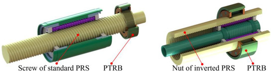
Figure 1.
Integration scheme of PTRB and PRS.
The structural composition and transmission scheme of DIELM are shown in Figure 2. There are two DIELM schemes due to different integration modes between a frameless motor and PRS. Scheme 1 is to integrate the permanent magnet patch of the frameless motor with the nut of the PRS through a rotating sleeve. Scheme 2 is to integrate the permanent magnet patch of the frameless motor with the screw of the PRS. DIELM has a similar structure to the integrated electro-mechanical actuator (IEMA) proposed in one of the authors’ previous papers [23], and DIELM integrates PTRB and PRS on the basis of IEMA [23]. Compared with IEMA, DIELM has fewer parts or components, so that the integration level of the module is improved, the volume is reduced, and the assembly and debugging processes are streamlined. DIERM has a simple structure that only integrates the servo motor, PTRB and sensor, no more details are provided in this paper.
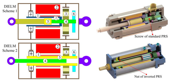
Figure 2.
Structural representation and three-dimensional diagram of two DIELM schemes.
In the field of robotics, many application scenarios will present a high demand on the output torque or output force of the module, so GIELM and GIERM schemes that integrate the reducer inside the module are needed. The structural representation and three-dimensional diagram of GIELM and GIERM schemes are shown in Table 1.

Table 1.
Transmission scheme of GIELM and GIERM.
The GIERM consists of the frameless motor, PTRB, PRS, reducer and sensor. There are two GIERM schemes in light of the inner-rotor and outer-rotor frameless motors:
- (1)
- In GIERM Scheme 1, the frameless motor adopts an inner-rotor form, which consists of the stator of the motor and the permanent magnet patch. The stator of the motor is installed inside the fixed sleeve, and the permanent magnet patch is installed outside the rotating sleeve. The ultra-thin support bearings are arranged on both sides of the frameless motor as support. The planetary gear is installed on the planet carrier and forms the planetary reducer together with the sun gear installed outside the rotating sleeve and the ring gear installed inside the fixed sleeve. PTRB is used for bearing the external load, whose inner ring is fixed and outer ring rotates. The fixed sleeve and driver are installed on the shell, respectively. The thermal conductive part can be installed inside or outside the fixed sleeve to help the stator of the motor dissipate heat. The temperature sensor is installed on the fixed sleeve to monitor the internal temperature of the module. The angle sensors are installed at the front and rear ends of the module, which are used to monitor the rotation angle of the motor and the output angle of the reducer. When the GIERM Scheme 1 is in operation, the frameless motor drives the rotating sleeve to rotate, the sun gear outside the rotating sleeve engages with the planetary gear, and the planetary gear drives the planetary carrier to output torque and rotational motion.
- (2)
- GIERM Scheme 2 is similar to GIERM Scheme 1, except that the former adopts an outer-rotor form. The stator of the motor is installed outside the fixed sleeve, and the permanent magnet patch is installed inside the rotating sleeve. The planetary gear is installed on the shell through the planet carrier and forms the planetary reducer together with the sun gear installed outside the rotating sleeve and the ring gear connected to the inner ring of PTRB. The inner ring of PTRB rotates and the outer ring is fixed. The power electronics, thermal conductive part, and multiple types of sensors can be arranged inside the module. When the GIERM Scheme 2 is in operation, the frameless motor drives the rotating sleeve to rotate, the sun gear outside the rotating sleeve engages with the planetary gear, and the ring gear drives the inner ring of PTRB to output torque and rotational motion.
In Table 1, labels 1 to 15 respectively represent: Permanent magnet; Stator; PTRB; Screw; Nut; Incremental angle sensor; Rotating sleeve; Absolute angle sensor; Fixed sleeve; Temperature sensor; Ring gear; Planetary gear; Sun gear; Power electronics; Rotating flange.
Based on GIERM Scheme 1, in GIELM Scheme 1, the nut of the inverted PRS is installed on the planetary carrier and the inner ring of PTRB through the connector. Based on GIERM Scheme 2, in GIELM Scheme 2, the nut of the inverted PRS is installed on the inner ring of PTRB. When GIELM Scheme 1 and Scheme 2 are in operation, the frameless motor and reducer drive the nut of the inverted PRS to rotate, and the screw of the inverted PRS outputs force and linear motion.
The working process of the GIELM and GIERM is illustrated below: When GIELM and GIERM receive the instruction from the measurement and control system, the power electronics controls the module to output force and position. Two angle sensors at the front and rear ends of the module and multiple temperature sensors inside the module provide feedback on the input and output positions of the module and the internal temperature information to the measurement and control system. Then the power electronics provide feedback on the output current and voltage to the measurement and control system.
In the field of robotics, as for the joint module, the frameless motor and the harmonic gear drive are usually used as the drive part and the transmission part. For the four transmission schemes in Table 1, the planetary reducer can be replaced with the harmonic gear drive or a brake can be integrated inside, according to the specific needs.
Characteristics of IEMA, DIELM, GIELM and GIERM and the comparison between them:
- (1)
- Compared with IEMA, all other transmission schemes replace the traditional ball bearing with PTRB which has a larger bearing capacity and occupies a smaller space. DIELM integrates PTRB and PRS on the basis of IEMA, which further improves the integration level of the module, reduces the number of the structural members and the overall volume, and streamlines the assembly process.
- (2)
- GIELM has a slightly larger radial dimension than IEMA, and there is no significant difference between them in the axial dimension. However, GIELM schemes can provide a larger output force due to the reducer integrated inside the module.
- (3)
- GIELM Scheme 1 and GIERM Scheme 1 adopt the inner-rotor frameless motor, exhibiting small rotational inertia, so the two schemes are applicable to the scenarios with higher requirements on the dynamic performance of the module. GIELM Scheme 2 and GIERM Scheme 2 adopt the outer-rotor frameless motor, exhibiting large output torque and rotational inertia, which can help the module run at a steady rate.
- (4)
- Both transmission schemes of GIELM adopt the inverted PRS as the transmission part. The inverted PRS has the advantages of a higher level of integration and better bearing capacity over the ball screw pair. Compared with the standard PRS, within an effective travel of 200 mm, the inverted PRS has a smaller outer diameter, thus giving the module a smaller volume and weight.
3. The Application of CFRP to IEMM
Given the characteristics of CFRP such as higher specific stiffness, specific modulus, and specific strength, it has been widely used in manufacturing the manipulator’s arm. Assuming that GIERM Scheme 1 is adopted for the waist rotary joint of the manipulator, the main bearing component is the fixed sleeve. When the module is in an idle state or needs to bear a larger axial force and overturning torque in operation, it can be beneficial to the lightweight and integrated design of the module when CFRP is used to design and manufacture the fixed sleeve. The density and specific heat capacity of CFRP are, respectively, as follows:
CFRP laminate is formed by the lamination of n layers of CFRP single-layer boards in different laying directions or the same laying direction. Different lay-up methods will have a direct impact on the thermal conductivity of the CFRP laminate. The thermal conductivity of the CFRP laminate is the sum of the thermal conductivity of each layer of single-layer boards in the heat transfer direction, which is shown as follows [24,25]:
where λi and Vi are the thermal conductivity and the volume fraction of the single-layer board in the heat transfer direction.
Based on careful reading and integration of relevant literature and the data provided by Weihai Guangwei Composite Material Co., Ltd., the basic performance indexes of T300 CFRP are as shown in Table 2 [26,27,28,29,30]:
Table 2.
Basic performance index of T300 CFRP.
There are many lay-up models for the laminate. To obtain high-performance laminates, a symmetric and balanced lay-up model [0°, 45°, −45°, 90°]s that only produces in-plane strain without a warping phenomenon was preliminarily adopted in this paper. The thickness and angle of each single layer of laminate were as shown in Figure 3.
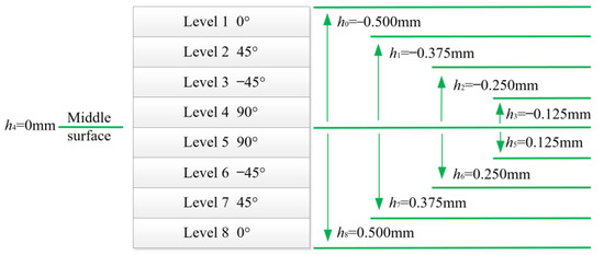
Figure 3.
The thickness and angle of each single layer of laminate.
A CFRP cylinder with an inner diameter of 89 mm, an outer diameter of 91 mm, and a length of 60 mm was taken as an example. Ansys workbench was used to analyze the strength of the CFRP laminate. The Tsai–Wu failure criterion, the one most consistent with the experimental data, and the relatively conservative first layer damage design criterion were used as the criteria for determining whether the CFRP laminate fails [24,25].
A curved surface with a diameter of 90 mm was created in the three-dimensional software and imported into Ansys workbench. It is worth noting that only shell meshing can be used in the ACP module of Ansys workbench and it is not possible to identify the solid meshing. As shown in Figure 4, the basic performance indexes of CFRP were added to the engineering data. Four layers of CFRP single-layer boards were laid according to the lay-up order of the laminate in Figure 3 on the upper and lower surfaces of the cylinder’s curved surface.
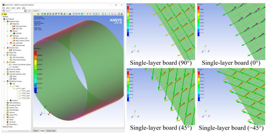
Figure 4.
Laminate model in the ACP module.
External load and Tsai–Wu failure criterion were added to the mechanical module [24,25]. Then a strength simulation analysis was conducted to obtain the stress nephogram of CFRP cylinder under an axial compression load of 100 KN and an axial tension load of 70 KN, as shown in Figure 5. According to the failure criterion, the CFRP cylinder did not reach the damage state, with the maximum stress of 1050.6 MPa and 735.4 MPa, respectively. Meanwhile, a strength simulation analysis was also conducted on the cylinder made of aluminum alloy 6061. Under an axial tension load of 70 KN, the maximum stress of aluminum alloy 6061 reached 313.8 MPa, but its yield strength was only 280 MPa. That is, under an axial compression load of 100 KN or an tension load of 70 KN, the aluminum alloy 6061 cylinder yielded. Since the density of CFRP was smaller than that of the aluminum alloy, the CFRP cylinder of the same size had a smaller weight.
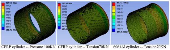
Figure 5.
Damage nephogram of CFRP cylinder under different axial load conditions.
Therefore, the application of CFRP as the material for manufacturing the main bearing component has certain advantages. The CFRP laminate preliminarily designed in this paper can be optimized in its lay-up method according to specific needs in the follow-up work, so as to further improve the strength and reduce the weight of the CFRP cylinder. Other components of IEMM, such as the rotating sleeve, have a small bearing capacity and size, so considering the manufacturing and assembly, aluminum alloy 6061 is used as the material of these parts and components.
4. Parameter Estimation and Calculation Models
In this section, IEMM’s parameter estimation and calculation models were built to avoid manually iterative design and lay a foundation for the following multidisciplinary and multi-objective optimization design.
4.1. Parameter Estimation Model of the Frameless Motor
A motor has many parameters, wherein the working voltage, rated torque, outer diameter, and rated speed are basic parameters set in the design phase. Other parameters, such as phase resistance, phase induction, peak torque, and internal thermal resistance, can be obtained through the calculation of basic parameters. Though the motors produced by major manufacturers have a wide range of power, due to the limited motor models and a large span between the performance parameters of adjacent motor models, the off-the-shelf products cannot easily satisfy the demands for optimization design.
In this paper, a parameter estimation model based on power exponent was built, which used some basic parameters as input parameters to preliminarily design the other parameters of the motor.
Taking the number of input parameters Gi as q, the output parameter G0 can be obtained through the parameter estimation model as follows [31]:
where k and λ are dimensionless coefficients.
When the number of input parameters q = 2, the expressions of the second-order model and the third-order model are as follows:
Taking the rated torque and outer diameter of the motor as input parameters, the related parameters of the UTM frameless motor and Kollmorgen TBM(S) frameless motor were estimated, respectively. For example, taking the motor weight as the output parameter, when the number of polynomial orders and the number of dimensionless coefficient λ increased, both the maximum difference and the mean difference between the estimated results and the sample parameters decreased, and the accuracy of the parameter estimation model improved. However, with the increase in the number of polynomial orders and the number of dimensionless coefficient λs, the accuracy improvement effect was reduced. When the third-order model was used for parameter estimation, the maximum difference and the mean difference barely changed.
The estimated ranges of rated torque, rated speed and rated power are 0.4~3.5 Nm, 2500~3800 rpm, and 160~1180 W, respectively. Taking the rated torque as the input parameter in the first-order parameter estimation model, and taking the rated torque and outer diameter of the motor as the input parameters in the second-order parameter estimation model, the difference between the estimated results of UTM motor parameters and the sample parameters were obtained, as shown in Table 3. As for the estimated results of the first-order model, the inner diameter and phase resistance had a relatively large difference, with a maximum difference of more than 20%. As for the estimated results of the second-order model, the maximum difference of parameter estimation was less than 8% and the mean difference was less than 5%, so the estimated results are relatively satisfactory.
Table 3.
The difference between the estimated results of motor parameters and the sample.
4.2. Parameter Selection Model of the Reducer and PRS
Different from the motor, domestic and foreign reducer and PRS manufacturers have provided a complete series of products and detailed performance parameters for their customers in the product manuals. Therefore, the rated torque or quality index can be used as the basis for product model selection; the parameter selection model based on the database can be built according to the product manuals and invoked by the optimization model in the multidisciplinary and multi-objective optimization process [32].
4.3. Heating Power Calculation Model
Heating in the IEMM is mainly caused by mechanical loss, winding copper loss of motor stator, and iron loss of motor stator. It is assumed that all energy losses convert into heat and that all heating elements are homogeneous heating elements [33]. The resistance temperature coefficient TCR of red copper is 1/234.5 °C and the resistance value of the winding at 30 °C is R30, so when the phase number of the motor is m, the winding copper loss of motor stator PCu is expressed as follows:.
The iron loss of motor stator is associated with the motor speed and core structure. The iron loss of motor stator PMIL is normally expressed as follows [34]:
where kh and ke represent hysteresis loss dimensionless constant and eddy-current loss dimensionless constant, with values of 48 and 0.055, respectively; Bm represents the magnetic flux density of the motor, with the value 1.5T [33]; n represents the motor speed and VMSC represents the volume of the motor stator core.
There is no oil filling around the brushless motor and its rotational speed is not high, so the mechanical loss caused by the brushless motor is minimal and can be neglected. Therefore, the mechanical loss of IEMM is mainly composed of the frictional loss caused by the reducer, PRS and PTRB during operation. According to the friction coefficient of reducer μJ, the load torque TL, and the output torque nL, the power loss of the reducer can be obtained as follows:
The power losses of the standard PRS and the inverted PRS are PSPRS and PRPRS, respectively. Their relationships with the contact angle αPRS, friction coefficient μPRS, and input power PPRSI can be expressed as follows [35,36]:
According to the friction torque of bearing MPTRB and the output speed nL, the power loss of PTRB can be expressed as follows [22,36]:
The input power of IEMM PIERM can be expressed as follows:
According to the armature equilibrium equation and torque equilibrium equation, the phase voltage U(t) and phase current I(t) of the motor are expressed as follows:
where Rm represents the resistance value of each phase of winding at a certain temperature, Lm and Cm represent the phase induction and torque constant of the motor, Tout represents the load torque at the output end of the motor, and Tloss contains the friction torque of the moving parts equivalent to the output end of the motor, and the product of the rotational inertia equivalent to the output end of the motor and the acceleration.
4.4. Thermal Resistance Calculation Model
Heat is mainly transmitted by three means, i.e., heat conduction, heat convection, and heat radiation. When the temperature difference is no more than 100 °C, the heat radiation can be neglected. The heat conduction of solids follows Fourier’s law. The thermal resistance of heat conduction Rth can be expressed as follows:
where λG represents the thermal conductivity of the material; AX represents the area of heat conduction; and th represents the thickness of solids in the heat transfer direction.
The radial thermal conductivity of the stator core is determined by the thermal conductivity of the silicon steel sheet, with a value of 38.5 W/(m°C). [37] The copper wire of the stator winding is basically surrounded by heat-insulating materials with a thermal conductivity of less than 0.23 W/(m°C). By referring to the relevant research results and the parameters of off-the-shelf products, the thermal conductivity of the stator winding along the wire is deemed similar to that of copper, and the equivalent thermal conductivity in the direction perpendicular to the wire is set as 8.6 W/(m°C) [32]. Moreover, the permanent magnet patch of the motor is deemed as a heat-conducting material the same as the aluminum alloy. Within IEMM, the thermal conductivity, density and specific heat capacity of metal materials are shown in Table 4.
Table 4.
Thermal conductivity, density and specific heat capacity of metal materials.
Considering that the surfaces of solids in mutual contact do not fully fit each other, an equivalent solid thin layer can be set to express the thermal contact resistance between such contact surfaces of solids. Because the motor stator of IEMM is installed on the inner wall of the heat-conducting shell in the form of adhesive binding, the thermal contact resistance is large. Therefore, an equivalent solid thin layer with a thickness of 0.5 mm and a thermal conductivity of 0.23 W/(m°C) is set between the motor stator and the heat-conducting shell. The ultra-thin bearing is installed inside the IEMM in an interference fit manner, so its thermal contact resistance can be neglected. An equivalent solid thin layer with a thickness of 0.2 mm and a thermal conductivity of 0.23 W/(m°C) is set on other surfaces of mutually contacting solids [38,39].
Heat convection will happen when the fluid flows over the surface of the component. There is no liquid filling inside or outside the IEMM studied in this paper, so only the convective heat transfer between air and solid surfaces is involved. The convective heat transfer coefficient is h and the thermal resistance of convective heat transfer Rth can be expressed as follows:
The coefficient of natural convective heat transfer is expressed as follows:
where Gr is the Grashof number; Nusselt number Nu is a dimensionless number; λL represents the thermal conductivity of air; l is the characteristic length; Pr is the Prandtl number, representing the dimensionless number of momentum exchange and heat exchange in fluid flow; C and n are relevant coefficients measured by the experiment. As for the cylinder, when Gr is less than 5.76 × 10⁸, C is 0.48 and n is 0.25.
The inner wall of the rotating sleeve is connected to the hollow manipulator’s arm, and it can be approximately considered that dry air at a constant temperature exists on the inner wall of the rotating sleeve. According to the Dittus–Boelter equation, the in-tube convective heat transfer coefficient between the inner wall of the rotating sleeve and the air is expressed as follows [40]:
where Re is the Reynolds number; n is the rotational speed; dMI is the bore diameter of the rotating sleeve; and l is the characteristic length.
The convective heat transfer coefficient of the motor’s air gap is affected by the motor speed and air gap diameter dxi. The convective heat transfer coefficient between the outer surface of the permanent magnet patch and the inner surface of the motor stator is expressed as follows [32]:
5. Multidisciplinary and Multi-Objective Optimization Design Calculation Model
In this paper, the IEMM that is designed according to GIERM Scheme 1 and applied to the waist joints of the manipulator was taken as an example for analysis. The specific demands for IEMM are shown as follows: the rated output torque is ≮40 Nm, the rated output speed is ≮30 rpm, the instantaneous maximum torque is ≮100 Nm, and the operating temperature of the motor, reducer and T300 CFRP shall not exceed 120 °C, 70 °C and 95 °C, respectively. Because the IEMM applied to the joints of the manipulator should have a small output speed and a large output torque, the frameless motor and the harmonic gear drive are usually used in combination.
5.1. Multi-Objective Optimization Design Model
In the traditional sequential design method and manual iteration process, the coupling and cooperative effects between the sub-systems are often ignored. This may result in an IEMM that is not optimal in terms of light weight, low power loss, and level of integration. Such contradiction in performance improvement needs to be solved by multi-objective optimization design. According to the parameter estimation and calculation models previously built, the rated torque of motor Tmotor, the outer diameter of motor dmotor, and the reduction ratio of reducer Ireducer were considered as design variables:
The value ranges of the design variables were set as follows:
The mass MIERM, input power PIERM and maximum diameter DIERM were used to measure the weight, power loss, and level of integration of IEMM. The minimum value of the objective function was considered as the optimal solution.
The design conditions that IEMM should meet were defined as constraint conditions:
where Tmotor and Tmomax represent the rated output torque and the instantaneous maximum torque of the motor; Treducer and Tredumax represent the rated output torque and the instantaneous maximum torque of the reducer, nmotor and nreducer represent the rated output speed of the motor and reducer; Cmotor, Creducer and Ccfrp represent the operating temperature of the motor, reducer, and T300 CFRP; and ηreducer represents the efficiency of the reducer.
For such a complicated system as IEMM, to avoid the convergence of the objective function to the locally optimal solution, a multi-objective genetic algorithm that is good at global searching was used in this paper for optimization solution, and the non-inferior solution in the operation process was reserved [41].
5.2. Thermal Network Model
To ensure that the temperature of all parts and components of IEMM is within the allowable limits during operation, a lumped parameter thermal network model needs to be built to conduct a simulation analysis of the temperature.
The following assumptions are proposed for the thermal network model:
- (a)
- Heat convection and heat conduction are considered, and heat radiation is neglected.
- (b)
- The same part or component is deemed as a temperature node with thermal resistance, and the heat and heat source are concentrated at the center of this part or component.
- (c)
- The temperature at any point within the part or component is identical and evenly distributed.
- (d)
- The stator of the motor is equivalent to a homogeneous solid.
The heat transfer path and thermal network model of GIERM Scheme 1 are shown in Figure 6 and Figure 7, including 15 temperature nodes, 27 thermal resistances, and 4 heat sources. The model consists of the solid domain and the fluid domain.
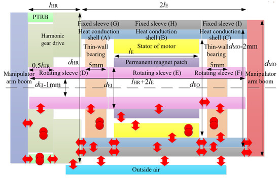
Figure 6.
Heat transfer path of GIERM Scheme 1.
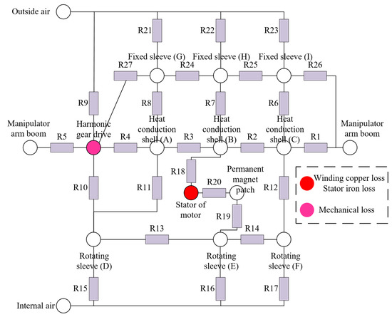
Figure 7.
Thermal network model of GIERM Scheme 1.
The following instructions are provided for the thermal network model:
- (a)
- Based on the design experience, the length of the heat-conducting shell and the fixed sleeve is normally twice the length of motor lE.
- (b)
- CFRP has a strong bearing capacity and a small density. To simplify the calculation and optimization process, the wall thickness of the fixed sleeve is set to a constant value, i.e., 1 mm. Therefore, the outer diameter of the heat-conducting shell is dMO−2 mm, and the inner diameter of the heat-conducting shell is the same as the outer diameter of the motor dEO.
- (c)
- The length of the rotating sleeve is lHR + 2lE, and its outer diameter is the same as the inner diameter of the motor dEI. Because the reducer with a large reduction ratio is normally used in the joint module of the manipulator, the rated output torque of the motor will be less than 1 Nm to satisfy the requirement placed on it. Using the calculation and simulation analysis methods in Section 3, it can be seen that when the wall thickness of the rotating sleeve is 0.5 mm, the requirement can be satisfied. So the inner diameter of the rotating sleeve can be expressed by dEI−1 mm.
- (d)
- The front output board and the rear fixed board are connected to the manipulator arm, and the temperature of the front output board, rear fixed board, and manipulator arm is considered to be constant to 20 °C.
- (e)
- The width range of the small-size and thin-wall bearing of NSK is 4~6 mm. For ease of calculation and optimization, the thickness of the front bearing and the rear bearing approximately takes a constant value, i.e., 5 mm.
- (f)
- When the heat emission conditions are met, the thinner the thickness of the rotating sleeve and the heat-conducting shell, the lighter the weight will be. However, when the diameter is constant, the thinner the thickness of the cylinder, the poorer the axial heat-conducting capability is. To obtain a relatively accurate thermal network model, the rotating sleeve, heat-conducting shell and fixed sleeve are divided into three segments, respectively.
6. Performance Optimization Design Process
Different working conditions will lead to the difference in the temperature rise of the parts and components. Under some working conditions, the parts and components have a small temperature rise, so there is no need to consider the heat-conducting structure; under some other working conditions, the parts and components have a large temperature rise, so the heat-conducting structure needs to be considered. The multi-objective optimization design model and the thermal network model were realized in Matlab and AMESim, respectively. Since Matlab does not contain the thermal network simulation model, the calculation amount is small, so Matlab occupies minimal computer resources. However, the thermal simulation in AMESim requires a large amount of calculation and occupies a huge computer resource. If the multi-objective optimization design with a thermal model is carried out directly, it will waste resources and time when the heat-conducting structure is not needed. Therefore, a segmented performance optimization design process was proposed in this paper, as shown in Figure 8.
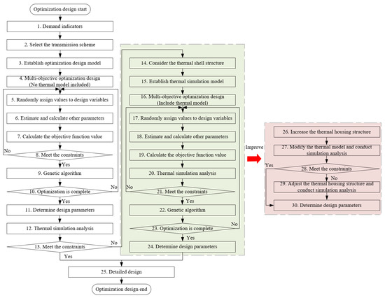
Figure 8.
Flow chart of IEMM performance optimization design.
Firstly, the manufacturer of the parts and components and the transmission scheme of IEMM are selected according to the demand indexes (without considering the heat-conducting shell), and the parameter estimation and calculation models are built. Then, a multi-objective optimization design model is built, and the mass, input power, and maximum diameter are optimized and solved using the genetic algorithm. Next, the optimal solution selected from the Pareto solution set is used to estimate and calculate other parameters, and a thermal network model is built for simulation analysis. If the thermal simulation results meet the requirements, a detailed structural design of IEMM is conducted according to the demand indexes and design parameters. If the thermal simulation results fail to meet the requirements, a multidisciplinary and multi-objective optimization design that considers the heat-conducting shell structure and thermal simulation is needed. When the heat-conducting shell structure is taken into consideration, e.g., steps 13–25, thermal simulation should be done once for each round of iteration, and it needs to be determined whether the temperature meets the constraint conditions. After the optimization design, the objective function value is selected and other parameter values are solved. Finally, the specific structural design of IEMM is finished. Nevertheless, the computing power of a computer is limited. When a multi-objective optimization design without the thermal model is carried out using a computer with an Intel Core i7-8700 CPU and a million loop iterations are performed, the operation time is only 0.33 h. Because the single operation time for the multi-objective optimization design with a thermal model is more than 1.5 s, when the number of loops reaches a million times, the total operation time will exceed 410 h. Considering the long operation time and low optimization efficiency, the performance optimization design process needs to be improved.
Input power is one of the performance optimization objects. The smaller the input power is, the smaller the heating power is, the lower the demand on the heat-conducting shell is, and the less the weight. Therefore, the thermal simulation can be removed from the loop. After steps 1–12 are finished, if the thermal simulation results fail to meet the requirements, steps 25–30 are executed. Then a heat-conducting shell structure is added for the IEMM under these parameters and the thermal network model is used to check whether the temperature of the parts and components meets the requirements. By changing the structural dimension of the heat-conducting shell, the design parameters that meet the constraint conditions are finally obtained. The aforesaid performance optimization design process including multidisciplinary optimization design, thermal network simulation check, and detailed structural design can save the performance optimization time and computer resources to the greatest extent.
7. An Example of IEMM Performance Optimization Design
7.1. Demand Index and Working Condition
The specific demand indexes were described in Section 4. Four main working conditions for GIERM are shown as Figure 9.
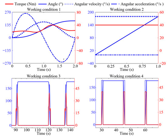
Figure 9.
Load spectrum of four working conditions.
Working condition 1: to avoid the sudden change of GIERM in torque and angular velocity during operation, the polynomial interpolation is used to plan the trajectories of the manipulator to obtain smooth torque, angular velocity, and angular acceleration curve.
Working condition 2: if the time is limited or an emergency occurs, IEMM needs to keep outputting 180°/s and 40 Nm.
Working condition 3: when GIERM works under working condition 1, it reciprocates once every 45 s, and the total working times is 300 s.
Working condition 4: when GIERM works under working condition 2, it reciprocates once every 30 s, and the total working time is 180 s.
7.2. Performance Optimization Design
The design variables and the constraint conditions have been explained in Section 5.1. After the relevant parameters were calculated according to Formulas (3)–(21) and the constraint conditions and range of parameters were set, multi-objective optimization design was carried out on GIERM under working condition 1. The population quantity and number of iterations were set to 10,000, the Pareto population fraction was set to 0.1, and the Pareto solution set obtained is shown in Figure 10. As shown in Figure 10, the Pareto solution set was segmented. This is because, in the multi-objective optimization process, the outer diameter of the reducer matching with the motor was no less than the outer diameter of the fixed sleeve. That is, the outer diameter of IEMM always equaled the outer diameter of the reducer. Because of the jumping in the outer diameter of the reducer in the product manual, the Pareto solution set also had segments and jumping.
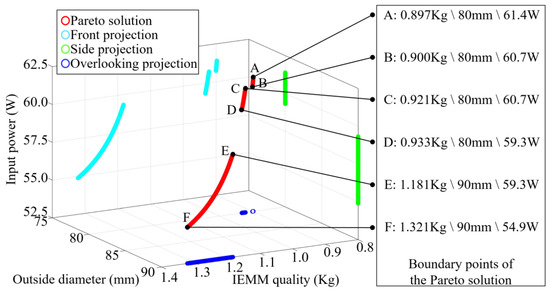
Figure 10.
Pareto solution obtained by optimization.
The objective function values corresponding to the six frontier points of the Pareto solution set are indicated in Figure 10. The input power of point C was equal to that of point B, but the quality of point C was greater than that of point B, that is, the performance of point C was inferior to that of point B, and the performance of point E was inferior to that of point D. Meanwhile, through the analysis of Figure 10, it can be seen that there is no point where all the performance indexes are better than others, so points A, B, D and F were selected for analysis. The design parameters at the four points and the relevant structural parameters of the module are listed in Table 5. The input power of point F was about 90% of that of the other three points, but the diameter at point F was larger and the weight at point F was about 140% of that of the other three points. Hence, point F is applicable to the scenarios that have a higher demand on input power rather than on weight and diameter. The maximum diameter of the other three points was the same, and the difference between them in input power and weight was no more than 4%. At point D, the weight was larger but the input power was lower, while at point A, the weight was smaller but the input power was higher. Therefore, point B with excellent comprehensive performance was selected for specific design and analysis in this paper.
Table 5.
Parameters corresponding to the performance optimization results.
7.3. Thermal Simulation and Analysis
The design parameters and thermal resistance at point B were obtained according to the parameter estimation and calculation models. A thermal simulation model was built in AMESim for simulation analysis. The simulation step size was set to 0.01 s.
- (a)
- When GIERM worked under working condition 1 for an uninterrupted 4800 s, the variation of power loss over time is shown in Figure 11. Based on the analysis of the load spectrum, in each cycle, the parameters of GIERM, such as torque and angular velocity, were constantly changing, resulting in the change of motor current and speed, which also caused the fluctuation of power loss in each working cycle. Though the output power of GIERM had no change, the power loss showed a gradually rising trend on the whole until it reached a steady state. This is because the copper loss of the stator winding was temperature-dependent. With a rise in temperature, the copper loss of the stator winding and the power loss both increased. When the temperature reached an equilibrium state, all the indexes tended to be stable.
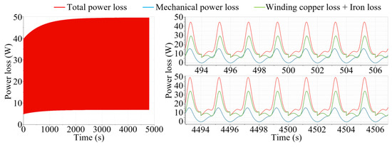 Figure 11. Variation of power loss over time.
The variation in the temperature of the parts and components is shown in Figure 12. A stepwise rise could be seen in the temperature of the motor stator and reducer. The variation in the temperature of CFRP was relatively mild. The system temperature reached an equilibrium state at 3000 s. The temperature of the motor stator, reducer and CFRP stabilized at 112 °C, 25 °C and 90 °C, respectively. Through analysis, under working condition 1, the temperature of all parts could meet the requirements in either continuous working mode or intermittent working mode. Therefore, there is no need to add a heat-conducting shell.
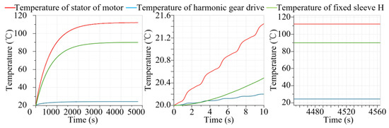
Figure 12.
Variation of temperature of parts and components over time.
- (b)
- When GIERM worked under working condition 2 for an uninterrupted 480 s, the power loss and the temperature of the parts and components saw a rapid increase over time but did not reached an equilibrium state, as shown in Figure 13. At 360 s, the temperature of the motor stator and CFRP was 119.9 °C and 93.1 °C, having reached the critical limit temperature. If GIERM needs to work uninterruptedly under working condition 2 for a long time, a heat-conducting shell needs to be added.
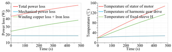 Figure 13. Variation of power loss and temperature over time (without the heat-conducting shell).
As shown in Table 4, though copper had a large thermal conductivity, the ratio of its thermal conductivity to density was only 0.044 (Wm2/(kg°C)). However, the ratio of the thermal conductivity to density for aluminum alloy was 0.086 (Wm2/(kg°C)). Therefore, aluminum alloy was preliminarily selected as the material of the metal heat-conducting shell.
After the heat-conducting shell was added for GIERM and the thermal resistance of each part was calculated, a thermal simulation model for the GIERM with a heat-conducting shell was built in AMESim. Through continuous iterative calculations, an aluminum alloy U-shaped cylinder with a wall thickness of 2 mm was finally determined to be the heat-conducting shell, and its weight was 0.051 kg. As shown in Figure 14, the power loss and temperature increased steadily over time. The system temperature reached an equilibrium state at 1400 s. The temperature of the motor stator, reducer and CFRP stabilized at 120.0 °C, 28.2 °C and 33.6 °C, respectively, meeting the requirements.
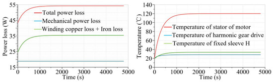
Figure 14.
Variation of power loss and temperature over time (with the heat-conducting shell).
The maximum diameter of the GIERM with a heat-conducting shell remained at 80 mm and the overall weight was 0.951 kg, a 5.6% increase from the weight of the GIERM without the heat-conducting shell. The change was relatively small and within the Pareto solution set. Though the optimization design process might have a relatively small error compared with the multi-software combined optimization design, it only took 0.4 h, thus showing a good practical value.
- (c)
- A simulation analysis was carried out on the GIERM without the heat-conducting shell that worked under working conditions 3 or 4, and the variation of temperature over time is shown in Figure 15. Due to the non-continuous working system and short single working time, the temperature of all parts had a small and stepwise increase over time and met the requirements under both working conditions. Hence, there is no need to add a heat-conducting shell.
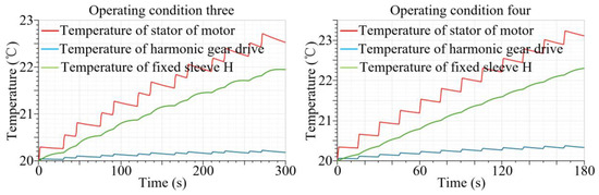 Figure 15. Variation of temperature of parts and components over time.
7.4. Detailed Design
Based on the performance optimization and thermal simulation analysis, a detailed design was carried out on the GIERM, and the three-dimensional structure obtained is shown in Figure 16. The frameless motor, harmonic gear drive, and multiple types of sensors are integrated inside the GIERM. Multiple temperature sensors are installed on the side face of the stator of the frameless motor, which are used for real-time comparative monitoring of the motor temperature. A power-off brake is arranged at the output end of the frameless motor. In case of failure in the GIERM, the power-off brake can perform power-off and self-locking actions to avoid the secondary damage caused by the free swing of GIERM to the system. An absolute angle sensor is installed at the front end of the GIERM for closed-loop control of the module. An incremental angle sensor is installed at the rear end of the GIERM for monitoring the rotation angle of the frameless motor and harmonic gear drive in comparison with the data of the absolute angle sensor. Multiple types of sensors can help achieve the health management of the module. PTRBs or high-performance off-the-shelf bearings can be installed at the front end of the GIERM according to the form and size of the load [22,42].
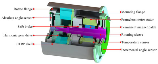
Figure 16.
Overall structure of GIERM.
To analyze the dynamic performance of the GIERM design, a system simulation model was built in AMESim, as shown in Figure 17. Current feedback, velocity feedback and position feedback were introduced to realize the closed-loop control of the module. Rotating clearance, coupling stiffness and damping were considered at the output end of the GIERM to simulate the real working conditions [23].
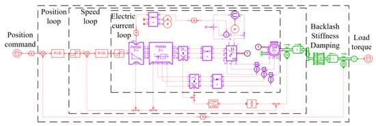
Figure 17.
System simulation model of GIERM.
The dynamic performance simulation results of the module under working conditions 3 and 4 were obtained by setting the simulation time of a single working cycle and a sampling frequency of 1000 Hz, as shown in Figure 18 and Figure 19. According to the analysis of the simulation results, GIERM had a good position tracking effect, without obvious steady-state error, hysteresis error or position jitters. The rise time for unidirectional movement was less than 1.4 s, and the maximum speed was 176°/s. The module exhibited a relatively rapid response speed and good control accuracy.
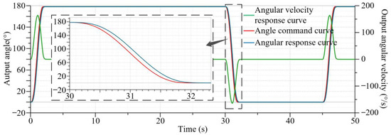
Figure 18.
Dynamic performance simulation results under working condition 3.
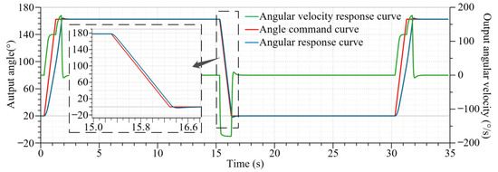
Figure 19.
Dynamic performance simulation results under working condition 4.
8. Conclusions
Multiple transmission schemes, a multidisciplinary and multi-objective optimization design calculation model, and a performance optimization design process for IEMM were proposed in this paper. The main efforts and important conclusions may be summarized as follows:
- (1)
- With small size and high level of integration as the goal, multiple types of IEMMs that can output linear or rotational motions were proposed, and a preliminary comparative analysis was carried out on the characteristics of these transmission schemes. The multiple types of sensors inside the IEMM can help achieve the health management of the module and enhance the reliability of the system. Meanwhile, the application of CFRP as the material for manufacturing the main bearing component contributes to the lightweight design of IEMM.
- (2)
- A multi-objective optimization design model of IEMM was built. The model adopted the rated torque of the motor, the outer diameter of the motor, and the reduction ratio of reducer as design variables, and light weight, low power loss, and high level of integration as optimization objects. A Pareto solution was obtained through the optimization solution by genetic algorithm. The model helped achieve better comprehensive performance in the early design phase of IEMM, thus avoiding the manually iterative design and improving the optimization design efficiency.
- (3)
- The high level of integration of the IEMM and the low thermal conductivity of CFRP bring challenges to the heat dissipation of the motor stator. Based on the calculation models of the heating power and thermal resistance, a lumped parameter thermal network model of IEMM was built to evaluate the temperature of all parts and components under different working conditions.
- (4)
- Because the thermal simulation occupies huge computer resources, the total time for the multidisciplinary and multi-objective optimization design would exceed 410 h. In response to this issue, a performance optimization design process including multidisciplinary optimization design, thermal network simulation check, and detailed structural design was proposed, saving the total time for optimization design to 0.33 h. Furthermore, a detailed design was conducted by taking one of the IEMM’s transmission schemes as an example. The results showed that the IEMM after performance optimization exhibited a relatively rapid response speed and good control accuracy.
Author Contributions
Conceptualization, S.Z. and Y.F.; methodology, S.Z. and X.H.; software, S.Z. and X.H.; validation, S.Z., Y.F. and J.S.; formal analysis, J.S.; investigation, Y.F. and J.S.; resources, J.S.; data curation, S.Z. and X.H.; writing—original draft preparation, S.Z. and X.H.; writing—review and editing, Y.F. and J.S.; supervision, J.S.; project administration, Y.F. and J.S.; funding acquisition, Y.F. All authors have read and agreed to the published version of the manuscript.
Funding
This research received no external funding.
Informed Consent Statement
Not applicable.
Data Availability Statement
The dataset that supports the central findings of this study is directly available in this article. Additional data can be requested from the corresponding author.
Conflicts of Interest
The authors declare no conflict of interest.
References
- Hirzinger, G.; Albu-Schaffer, A.; Hahnle, M.; Schaefer, I.; Sporer, N. On a new generation of torque controlled light-weight robots. In Proceedings of the 2001 ICRA. IEEE International Conference on Robotics and Automation (Cat. No.01CH37164), Seoul, Republic of Korea, 21–26 May 2001; pp. 3356–3363. [Google Scholar] [CrossRef]
- Hirzinger, G. Mechatronics for a new robot generation. IEEE/ASME Trans. Mechatronics 1996, 1, 149–157. [Google Scholar] [CrossRef]
- Shepherd, S.; Buchstab, A. KUKA Robots On-Sitep. In Robotic Fabrication in Architecture Art and Design; Springer Science & Business Media: Berlin/Heidelberg, Germany, 2014; pp. 373–380. [Google Scholar]
- Collaboration Robots Letting Auto Manufacturing More Agile and Safe. Auto Parts 2015, 1, 8.
- Wang, Z. Development of Modular Reconfigurable Manipulator System; Anhui University of Technology: Maanshan, China, 2020. [Google Scholar]
- Zheng, Z. Development of Modular Main Robot; South China University of Technology: Guangzhou, China, 2013. [Google Scholar]
- Jin, L.; Wang, C.; Xia, K.; Mao, J.; Lu, F. Design of Compact Embedded Torque Sensor Robot Joint. Sci. Technol. Eng. 2021, 21, 10356–10361. [Google Scholar]
- Zhang, Y.; Zhang, W.; Hesselbach, J.; Kerle, H. Development of a two-degree-of-freedom piezoelectric rotary-linear actuator with high driving force and unlimited linear movement. Rev. Sci. Instrum. 2006, 77, 035112. [Google Scholar] [CrossRef]
- Bissal, A. Modeling and Verification of Ultra-Fast Electro-Mechanical Actuators for HVDC Breakers; KTH: Stockholm, Sweden, 2015. [Google Scholar]
- Persson, J.; Feng, X.; Wappling, D.; Ölvander, J. A framework for multidisci-plinary optimization of a balancing mechanism for an industrial robot. J. Robot. 2015, 2015, 389769. [Google Scholar] [CrossRef][Green Version]
- Mondol, S. Design Optimization of a Support for the Storage Ring Quadrupole Magnet in a Synchrotron Radiation Facility; University of Saskatchewan: Saskatoon, SK, Canada, 2019. [Google Scholar]
- Han, X. System-Level Design of Variable Displacement Electro-Hydrostatic Actuator; Beijing University of Aeronautics and Astronautics: Beijing, China, 2019. [Google Scholar]
- Lightcap, C.; Banks, S. Dynamic identification of a mitsubishi pa10-6ce robot using motion capture. In Proceedings of the 2007 IEEE/RSJ International Conference on Intelligent Robots and Systems, San Diego, CA, USA, 29 October–2 November 2007; pp. 3860–3865. [Google Scholar] [CrossRef]
- Hirose, M.; Ogawa, K. Honda humanoid robots development. Philos. Trans. R. Soc. A Math. Phys. Eng. Sci. 2007, 365, 11–19. [Google Scholar] [CrossRef] [PubMed]
- Trebi-Ollennu, A.; Volpe, R.; Bonitz, R.G.; Robinson, M.; Carsten, J. In situ robotic arm operations. IEEE Robot. Autom. Mag. 2009, 16, 34–43. [Google Scholar] [CrossRef]
- Du, S. Advanced Composites and Aerospace. J. Compos. 2007, 24, 1–12. [Google Scholar]
- Sui, X.; Guo, H.; Li, X.; Lin, F.; Li, G. Structural design and properties of Carbon fiber reinforced epoxy composite manipulator. New Chem. Mater. 2020, 48, 235–237+243. [Google Scholar]
- Ma, H. Design, Fabrication and Dynamic Simulation Analysis of Carbon Fiber Composite Arm; Harbin Institute of Technology: Harbin, China, 2017. [Google Scholar]
- Hirzinger, G.; Sporer, N.; Albu-Schaffer, A.; Hahnle, M.; Krenn, R.; Pascucci, A.; Schedl, M. DLR’s torque-controlled light weight robot III-are we reaching the technological limits now? In Proceedings of the Proceedings 2002 IEEE International Conference on Robotics and Automation (Cat. No.02CH37292), Washington, DC, USA, 11–15 May 2002. [Google Scholar] [CrossRef]
- Hemmerling, T.M.; Taddei, R.; Wehbe, M.; Zaouter, C.; Cyr, S.; Morse, J. First robotic tracheal intubations in humans using the Kepler intubation system. Br. J. Anaesth. 2012, 108, 1011–1016. [Google Scholar] [CrossRef]
- Wang, W.; Tang, F.; Zheng, C.; Xie, T.; Ma, C.; Zhang, Y. Prototyping a novel compact 3-DOF hydraulic robotic actuator via metallic additive manufacturing. Virtual Phys. Prototyp. 2021, 17, 617–630. [Google Scholar] [CrossRef]
- Zheng, S.; Fu, Y.; Wang, D.; Pan, J.; Li, L.; Wang, J. A Novel Planetary Thread Roller Bearing: Design and Analysis of Load Characteristic. J. Mech. Des. 2020, 143, 064501. [Google Scholar] [CrossRef]
- Zheng, S.; Fu, Y.; Wang, D.; Zhang, W.; Pan, J. Investigations on system integration method and dynamic performance of electromechanical actuator. Sci. Prog. 2020, 103, 003685042094092. [Google Scholar] [CrossRef] [PubMed]
- Wu, K.; Nuanyai, P.; Zhang, H.; Tang, G. Anisotropic thermal conductivity of resin-based carbon fiber composites. J. Eng. Thermophys. 2021, 42, 1282–1287. [Google Scholar]
- Gou, J.J.; Zhang, H.; Dai, Y.J.; Tao, W.-Q. Numerical prediction of effective thermal conductivities of 3D four-directional braided composites. Compos. Struct. 2015, 125, 499–508. [Google Scholar] [CrossRef]
- Dong, K.; Liu, K.; Pan, L.; Gu, B.; Sun, B. Experimental and numerical investigation on the thermal conduction properties of 2.5D angle-interlock woven composites. Compos. Struct. 2016, 154, 319–333. [Google Scholar] [CrossRef]
- Zhao, Y.; Song, L.; Li, J.; Jiao, Y. Multi-Scale Finite Element Analyses of Thermal Conductivities of Three Dimensional Woven Composites. Appl. Compos. Mater. 2017, 24, 1525–1542. [Google Scholar] [CrossRef]
- Long, W.; Zheng, X.; Zang, J. Review of research progress on thermal properties of carbon fiber composites. Appl. Chem. Ind. 2019, 48, 2251–2255. [Google Scholar]
- Gibson, L.; Zhang, X.; Yu, Y.; Lu, X. Principles of Composite Material Mechanics; Shanghai Jiao Tong University Press: Shanghai, China, 2019. [Google Scholar]
- Campbell, F.; Chen, X.; Liu, P.; Yang, H. Structural Composite Materials; Shanghai Jiao Tong University Press: Shanghai, China, 2019. [Google Scholar]
- Giorgi, F.D.; Budinger, M.; Hazyuk, I.; Reysset, A.; Sanchez, F. Reusable Surrogate Models for the Preliminary Design of Aircraft Application Systems. AIAA J. 2021, 59, 2490–2502. [Google Scholar] [CrossRef]
- Gong, F.; Liu, S. Reducer automatic selection and parametric drawing CAD system development. J. Hubei Univ. Technol. 2005, 20, 12–14. [Google Scholar]
- Wei, Y.; Meng, D.; Wen, J. Internal Heat Exchange of Motor; China Machine Press: Beijing, China, 1998. [Google Scholar]
- Chunting, M.; Gordon, R.S.; Richard, B. Modeling of iron losses of permanent-magnet synchronous motors. IEEE Trans. Ind. Appl. 2003, 39, 734–742. [Google Scholar] [CrossRef]
- Karam, W.; Mare, J.C. Modelling and simulation of mechanical transmission in roller-screw electromechanical actuators. Aircr. Eng. Aerosp. Technol. 2009, 81, 288–298. [Google Scholar] [CrossRef]
- Hu, X.; Cao, L.; Luo, Y.; Chen, A.; Zhang, E.; Zhang, W.J. A Novel Methodology for Comprehensive Modeling of the Kinetic Behavior of Steerable Catheters. IEEE/ASME Trans. Mechatron. 2019, 24, 1785–1797. [Google Scholar] [CrossRef]
- Yang, S.; Tao, W. Heat Transfer; Higher Education Press: Beijing, China, 2006. [Google Scholar]
- Hu, S. Thermodynamic Modeling and Passive Enhanced Heat Dissipation Design of Double-Winding High-Speed Permanent Magnet Motor; Beijing University of Aeronautics and Astronautics: Beijing, China, 2017. [Google Scholar]
- Sanchez, F.; Budinger, M.; Hazyuk, I. Dimensional analysis and surrogate models for the thermal modeling of Multiphysics systems. Appl. Therm. Eng. 2017, 110, 758–771. [Google Scholar] [CrossRef]
- Nishikawa, K.; Fujita, K. Heat Transfer; Ordnance Industry Press: Beijing, China, 1990. [Google Scholar]
- Zhang, C.; Jia, B.; Zou, J. Power Allocation Optimization of Diesel-Electric Hybrid Ship Based on Multi-objective Genetic Algorithm. Comput. Appl. Softw. 2021, 38, 26–31. [Google Scholar]
- Zheng, S.; Fu, Y.; Wang, D.; Pan, J.; Liu, Z.; Chen, J. Characteristics Analysis and Optimization of the Structural Parameters of PTRB. Machines 2022, 10, 1051. [Google Scholar] [CrossRef]


Disclaimer/Publisher’s Note: The statements, opinions and data contained in all publications are solely those of the individual author(s) and contributor(s) and not of MDPI and/or the editor(s). MDPI and/or the editor(s) disclaim responsibility for any injury to people or property resulting from any ideas, methods, instructions or products referred to in the content. |
© 2023 by the authors. Licensee MDPI, Basel, Switzerland. This article is an open access article distributed under the terms and conditions of the Creative Commons Attribution (CC BY) license (https://creativecommons.org/licenses/by/4.0/).