Article

Double Redundancy Electro-Hydrostatic Actuator Fault Diagnosis Method Based on Progressive Fault Diagnosis Method

1
Engineering Training Center, Beihang University, 37 Xueyuan Road, Haidian District, Beijing 100191, China
2
School of Mechanical Engineering and Automation, Beihang University, 37 Xueyuan Road, Haidian District, Beijing 100191, China
*
Author to whom correspondence should be addressed.
Actuators 2022, 11(9), 264; https://doi.org/10.3390/act11090264
Submission received: 1 August 2022 / Revised: 7 September 2022 / Accepted: 9 September 2022 / Published: 13 September 2022
(This article belongs to the Special Issue Advanced Actuators for Aerospace Systems)

Abstract

:
The electro-hydrostatic actuator (EHA) is the key component of most electric aircraft, and research on its fault diagnosis technology is of great significance to improve the safety and reliability of aircraft flight. However, traditional fault diagnosis methods only focus on partial failures and cannot completely diagnose the whole EHA system. In this paper, the progressive fault diagnosis method (PFDM) is proposed for overall diagnosis of whole EHA system, which can be divided into four levels for health detection and fault diagnosis of the overall EHA system. PFDM combines fault diagnosis methods based on Kalman filter, threshold, logic, and EHA system analysis model to diagnose the whole EHA system layer by layer. At the same time, in order to ensure the normal operation of the EHA system after fault diagnosis, double redundancy design is creatively carried out for the EHA system to facilitate system reconstruction after fault detection. It can be continuously modified according to different EHA system parameters and measured signals to improve the accuracy of fault diagnosis. The experimental results show that PFDM can accurately locate and identify 22 faults of the double redundancy EHA system by using the accurate EHA system mathematical model. PFDM improves the fault diagnosis response time to 4 ms, greatly improving the safety and reliability of the double redundancy EHA system.

1. Introduction

Under the development trend of more/all electric aircraft, as a new type of power-by-wire (PBW) actuator, the electro-hydrostatic actuator (EHA) has become the key component of more electric aircraft to realize flight control, and has been playing an important role in the actuation system of modern civil and military aircraft [1,2,3]. Compared with the electro-mechanical actuator (EMA), which is another kind of PBW, the EHA is more secure because it is free of jamming problems caused by lead screw transmission. With the development of aviation technology, as the future leading actuator, the EHA has garnered more and more attention of scholars and engineers [4]. How to improve the reliability of EHA and reduce the probability of failure in actual operation has become a research hotspot.
Modern digital flight control systems have increasingly higher requirements for reliability. In addition, there are several methods for reliability improvement, including the use of high reliability components, the use of redundancy technology, and fault-tolerant control methods. At present, the safety and reliability index of flight control and actuation systems of civil large aircraft put forward by countries all over the world is generally 10−9/h [5]. To achieve such a high safety and reliability index, redundancy technology must be adopted. The methods of redundancy can be divided into two categories: hardware redundancy and analytical redundancy [6]. The concept of hardware redundancy is to compare or analyze signals obtained from different hardware (such as different sensors), and the main purpose of analyzing redundancy is to first build a simultaneous interpreting system and analyze the relationship or difference between observed behavior and prediction behavior. Philippe G. considered the detection of oscillation faults on the A380 and used analytical redundancy to detect faults [7]. A nonlinear actuator model was used to generate a residual on which the failure was detected by oscillation counting. This method is currently used on the A380, and it provides very satisfactory results in terms of robustness and detection. Aiming at the problems of model uncertainty, computational complexity, and non-robustness of traditional methods, Chi C.Z. proposed a real-time diagnosis and regulation method of single redundant sensor flight control system based on analytical redundancy. The results show that this method is effective, robust, and fast in sensor fault diagnosis of flight control systems [8]. The United States Air Force (USAF) applied serial double redundancy EHA to the main flight control surfaces of a series of military aircraft—such as F-16, F/A-18, and F-35—which proved that double redundancy EHA has higher reliability than traditional EHA to reduce EHA failure rate [9,10]. Different from the series EHA of the USAF, we design a parallel double redundancy EHA system, which makes backup of the hardware parts that are more prone to failure for system reconfiguration redundant. This structure has achieved accurate experimental results and high reliability.
Fault diagnosis technology is widely used in the field of aerospace, including civil transport aircraft, UAVs, reusable launch vehicles, near space launch vehicles, satellites, and other aircraft [11]. Fault diagnosis technology can be divided into analytical model-based fault diagnosis and signal-based fault diagnosis [12]. Fault diagnosis method based on signals has a large amount of data processing and high requirements for hardware facilities, so it is difficult to diagnose a system in real time [13]. The analytical model-based method is to diagnose and process the measured information according to a certain mathematical method on the basis of clarifying the mathematical model of the diagnosis object [14,15]. Davor L. et al., proposed a model-based fault detection and isolation algorithm by using the nonlinear system identification method of the neural network model on the basis of establishing the detailed mathematical model of the whole electro-hydraulic system [16]. The combination of two fault diagnosis methods is a future research direction. Andrea M. et al., established the nonlinear model of electro-hydraulic servo actuators (EHSA), which is realized by integrating the physical equation and measuring the actual parameters of the system. The environmental conditions and interferences were considered in the establishment process, and have been verified by the test run on the flight control actuator of civil aircraft [17]. In addition, methods based on empirical mode decomposition, wavelet transform, morphological signal processing and spectral analysis have been widely used in fault diagnosis of aircraft control systems [18,19,20]. Chinniah Y. studied the feasibility of estimating the viscous damping coefficient and effective bulk modulus parameters of the EHA system based on extended Kalman filter. The results show that this method can detect the changes of system parameters caused by faults [21,22,23]. Similar to the above methods, we also built the nonlinear model of EHA. Based on the actual system data, we gradually approach the operation state of the actual system by adjusting the parameters of the control algorithm and combine it with the method based on logic and threshold to jointly diagnose the fault.
In this paper, an analytical model method is applied for fault diagnosis of double redundancy EHA for the advantage of clear control system, good ductility of interpolation and extrapolation, strong portability, and convenience for analysis and real-time diagnosis. It is also a method with relatively complete research which is the most widely used. However, due to the existence of nonlinearity and complexity, it is difficult to establish a perfect model for aircraft system or its subsystems, such as a drive control system [24,25,26]. In order to solve this problem, we combine fault diagnosis technology based on a system analytical model and signal processing, and carry out hierarchical fault diagnosis in combination with the characteristics of a double redundancy EHA system. Based on the mathematical model of double redundancy EHA, the simulation model of the whole EHA system is established by means of signal flow and computer program, constantly adjusting and designing the parameters, and adopting a more accurate integration method.

2. Methods

As shown in Figure 1, the PFDM design is generally divided into three parts: structural design; model construction and verification; and software and hardware design. After completing the PFDM design, experiments are carried out to verify the algorithm. Next, the design method of PFDM will be introduced in sequence.

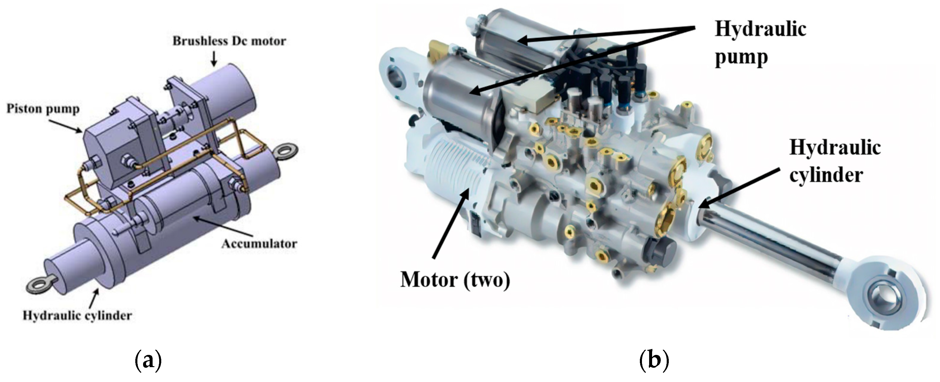
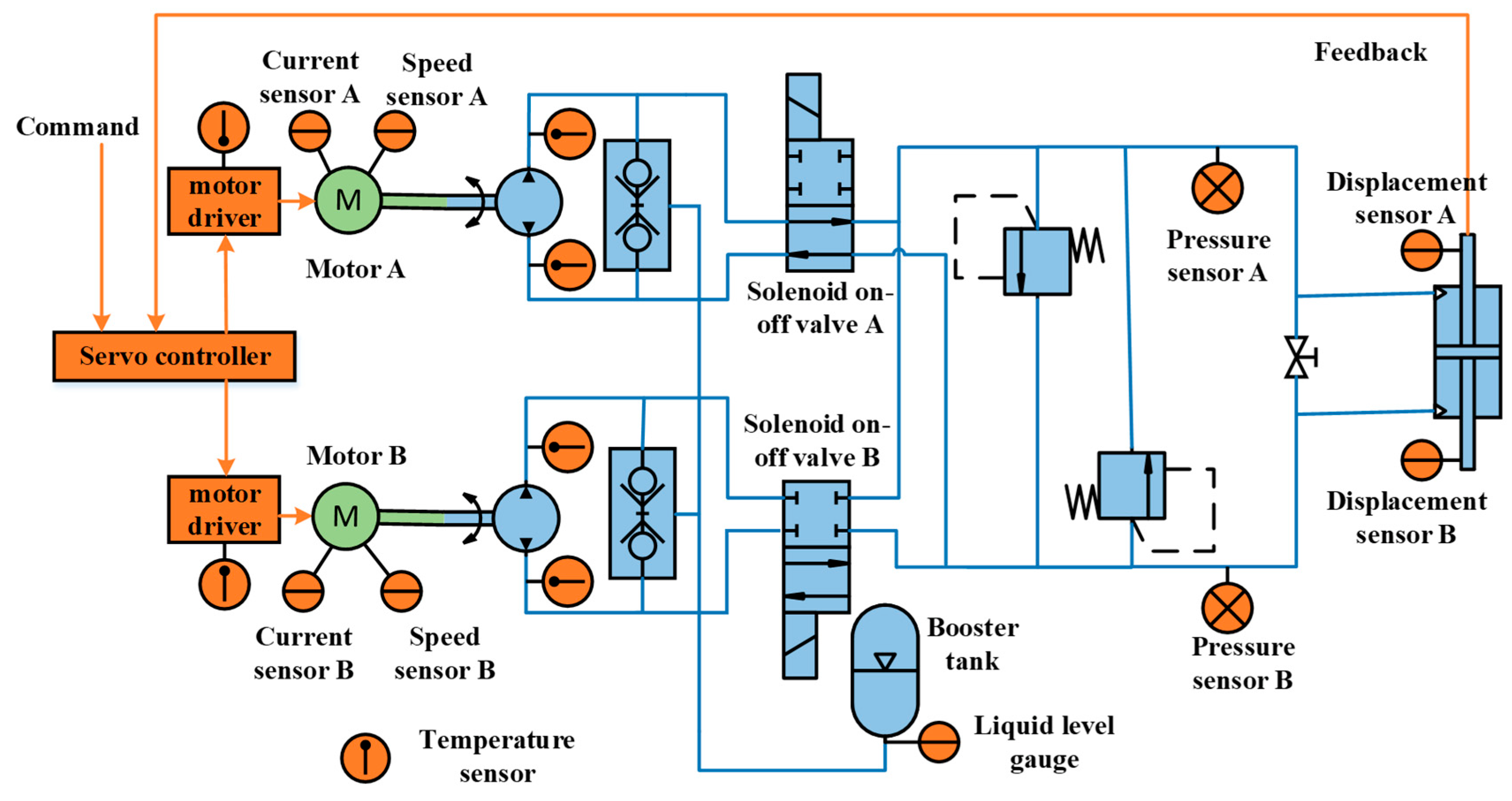
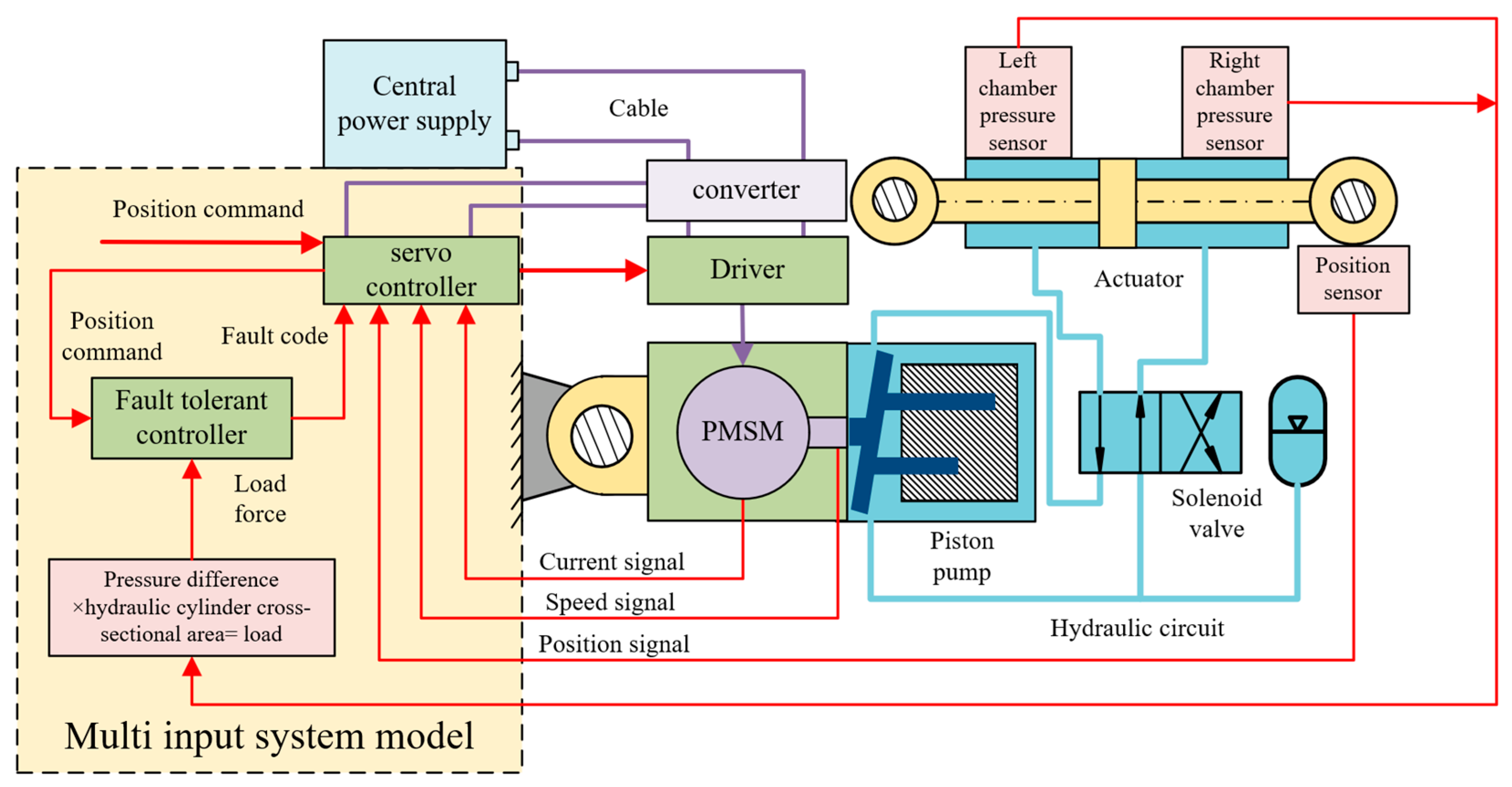
2.1. Structural Design and Sensor Layout of Double Redundancy EHA

The traditional EHA has only one motor and a group of hydraulic channels, as is shown in Figure 2a. In order to meet the system reconstruction requirements after fault diagnosis, the authors design a double redundancy EHA system to back up the faulty part. The object of this study is a parallel double redundancy EHA servo system, which is composed of a servo driver, a set of servo actuators, and a set of cables. The servo actuator is composed of two servo motor bodies, two hydraulic pumps, a set of hydraulic cylinders, and a group of hydraulic accessories. The system adopts a high-performance digital signal processor DSP as a servo driver and adopts the “one control two” mode, that is, one servo driver can control and drive two servo motors. The physical drawing of double redundancy EHA physical prototype on F-35 is shown in Figure 2b. The structural diagram and sensor layout of the double redundancy EHA system are shown in Figure 3.
According to the structure in Figure 3, a control value signal is fed to the driver, and the servo motor starts to work according to the assigned command. The double redundancy EHA system is divided into the main channel and the backup channel. The main channel is used when the system has no fault. Once a fault occurs, the system switches channels and uses the backup channel. The motor drives the hydraulic pump to rotate, and it outputs the corresponding flow to promote the movement of the cylinder piston rod. When the piston rod moves, the displacement sensor installed on the hydraulic cylinder outputs the feedback signal of the hydraulic cylinder position to the servo controller and compares it with the command signal to form a closed-loop control. With the continuous change of the command signal, the position of the cylinder piston rod also changes in real time with the command signal. In the working process of the double redundancy EHA servo system, the fault-tolerant controller monitors the motion state of the system in real time.
In order to monitor the operation status of EHA system in real time, according to the determined sensor type and the needs of fault monitoring, the layout position of sensors in the double redundancy EHA system is preliminarily determined, as shown in Table 1.
It includes six temperature sensors to monitor the temperature of the driver and hydraulic pump during operation; four current sensors to collect the two of three-phase currents of two permanent magnet synchronous motors respectively, and one current sensor is used to measure the power bus current; two pressure sensors are used to collect the pressure of the left and right chambers of the hydraulic cylinder and one is the booster oil tank; two displacement sensors are used to collect displacement data of hydraulic cylinders; one liquid level gauge is used to monitor the liquid level of booster oil tank; two speed sensors are used to collect the speed of the motor when it is working, and one voltage sensor is used to measure the power bus voltage.

2.2. Common Fault Types and Judgment Scheme

2.2.1. Fault Type of Double Redundancy EHA System

The whole double redundancy EHA system consists of DSP driver, permanent magnet synchronous motor, axial piston pump, hydraulic cylinder, energy storage booster oil tank, solenoid valve, high-pressure safety valve, and damping bypass valve. The above parts can be classified as electrical system and hydraulic system. Therefore, the fault types of the double redundancy EHA system can be divided into electrical fault and hydraulic fault. In the hydraulic system, different hydraulic components will have different types of faults under different working conditions [29]. Next, all the faults mainly diagnosed by this fault diagnosis algorithm are determined according to the possible faults of each component, as shown in Table 2.
Due to different fault types, the fault detection and location methods used are also different. According to a total of 22 fault types determined, it is now determined which method to use to distinguish each fault and how to distinguish it.

2.2.2. Fault Diagnosis Based on Threshold

(1)
Driver overcurrent fault
The aircraft control system operates in a complex and relatively bad environment. The motor driver may have sudden conditions—such as high temperature, mechanical overload, AC line transients, and wiring errors—which will lead to excessive current flowing into the motor driver system, resulting in driver damage. In order to monitor the occurrence of this situation in real time, we continuously collect the driver bus current data and set the driver overcurrent threshold. Once the collected current data exceed the threshold, it is considered that a driver overcurrent fault has occurred [30].
(2)
Driver overvoltage and undervoltage fault
During the operation of the double redundancy EHA system, the over-voltage phenomenon of the driver will occur if the braking circuit is damaged, the braking resistance is not connected, there is damaged or open circuit, and the voltage generated by the inverter has nowhere to be released due to the motor stopping or reversing. Circuit board failure, power fuse damage, soft start circuit failure, rectifier damage, and other circumstances will lead to undervoltage failure of the driver [30].
In order to detect the above two kinds of faults, we collect the bus voltage value of the driver and set the overvoltage threshold and undervoltage threshold of the driver. If the bus voltage exceeds the overvoltage threshold or is lower than the undervoltage threshold during normal operation, the driver is considered to have overvoltage and undervoltage faults.
(3)
Abnormal drive heating fault
The wrong wiring of the servo motor circuit and the failure of the circuit board of the driver may lead to abnormal heating of the driver. To detect this fault, we collect the temperature value of the motor driver and monitor the temperature change of the driver in real time [30]. If the driver temperature values collected for 10 consecutive samplings exceed the set driver temperature threshold, it is considered that a driver abnormal heating fault has occurred.
(4)
Abnormal pump heating fault
During the operation of the double redundancy EHA system, the hydraulic pump may be abnormally heated due to poor characteristics of oil viscosity and temperature, great difference in viscosity changes during use, hydraulic oil containing a lot of water, or the drain pipe connecting the hydraulic pump is flattened or blocked. The fault diagnosis logic for this phenomenon is similar to the above driver heating fault. The temperature values of the oil inlet and outlet of the hydraulic pump are collected in real time. If the temperature values collected for 10 consecutive samplings exceed the set threshold, it is considered that an abnormal pump heating fault has occurred.

2.2.3. Fault Diagnosis Based on Logical Judgment

(1)
Redundant displacement sensor and motor speed sensor fault
Due to the redundant setting of the displacement sensor, after collecting the displacement value, first compare the two collected values, and set the threshold to check the difference. If the two collected deviations are large, one of the sensors is considered to be damaged. Because the displacement of the hydraulic pump used in this study is constant, and the hydraulic oil output by the pump comes to the two chambers of the actuator through the pipeline, without considering the leakage of the hydraulic pump and hydraulic cylinder and the elastic deformation of the oil, the speed of the motor is proportional to the displacement speed of the actuator. Because the collected value of the displacement sensor can approximately calculate the speed of the hydraulic cylinder, and the speed of the hydraulic cylinder is in direct proportion to the motor speed when there is no leakage in the hydraulic system, under the assumption that there is only one fault in the system, the collected value of the motor speed can be used to check the displacement sensor, which cannot only judge the fault of the displacement sensor, but also locate which sensor has failed. As for the so-called three sensors, the third one can be determined by the collected values of the two sensors. At the same time, it is noted that if there is leakage in the hydraulic system, the situation is consistent with the above. At this time, we will distinguish it by combining the collected value of the liquid level gauge in the booster oil tank. If the liquid level gauge changes little, it is considered to be a sensor fault. If the collected value of the liquid level gauge decreases significantly, it is considered that there is a leakage of the hydraulic system.
(2)
Driver phase failure
Under normal circumstances, the three-phase current is a sine wave with a phase difference of 120° electrical angle. When a phase output phase loss occurs, the phase current of the phase loss will be close to 0, and the other two-phase currents will show a phase difference of 180°, and the current amplitude will become larger. If the three-phase current is 0 when two or three phases are missing, the missing phase can be directly judged. Based on these characteristics, whether or not the driver has phase failure can be comprehensively judged [31].
(3)
Motor immobility fault
There are many reasons why the motor cannot be started normally, such as bearing damage or loose end cap screws of permanent magnet synchronous motor, low voltage of stator winding, open circuit of stator winding, broken bars of engine cage or poor contact at the joint. According to this phenomenon, after detecting the position command from the controller, we monitor the changes of hydraulic cylinder displacement, motor speed, and other state variables. If the above state variables do not change much within five diagnostic cycles (20 ms), it is considered that the motor cannot be started normally.
(4)
Oil pump stuck fault
The sticking failure of the hydraulic oil pump may be caused by the blockage of the oil suction pipe, the hydraulic oil cannot meet the oil suction capacity of the pump, the hydraulic pump is burnt out and cannot work, and the one-way valve is damaged. According to the phenomenon that the current is too high, the speed is low and the displacement of the hydraulic cylinder changes little when the oil pump is stuck, based on the experimental data, motor speed, and current and displacement signals of the hydraulic cylinder can be integrated for diagnosis. If the motor speed is declines for a period of time, the current exceeds the threshold, and the change of the collected value of the displacement sensor is very small, it is considered that the oil pump is stuck.

2.2.4. Fault Diagnosis Based on Double Redundancy EHA Analytical Model

Since the state quantities involved in the EHA model include displacement, speed, current, pressure, etc., each state quantity at that time can be collected and input into the mathematical model in real time, the state quantity after a certain time can be calculated and predicted in real time, and then the state quantity at that time can be collected and compared. Therefore, based on the analytical model, it can be judged that the state quantities include motor winding open circuit, short circuit fault, pump output pressure abnormal fault, pump leakage fault, hydraulic cylinder creeping stuck fault, etc. The specific fault diagnosis logic is as follows.
(1)
Motor winding open circuit fault
In case of motor winding open circuit, the motor cannot work normally, and the three-phase current of the driver is unbalanced, which will be accompanied by a lot of noise. Therefore, according to this phenomenon, the two-phase current of the driver can be collected. If the two-phase current changes greatly and irregularly, and the third phase circuit current is not 0, it can be judged that a motor winding open circuit fault has occurred [32].
(2)
Motor winding short circuit fault
When there is a short-circuit fault in the motor winding, the three-phase current will be unbalanced, the load capacity of the motor will be reduced or the hydraulic pump will not be driven, and the motor will heat seriously or even smoke. According to this phenomenon, the driver current can be collected. When the three-phase current of the driver is unbalanced, and the motor speed value is collected 10 consecutive times, there is a significant decrease and approaches zero, which means that the motor speed suddenly decreases, and it can be judged that the motor has a winding short-circuit fault [32].
(3)
Abnormal pump output pressure
Generally speaking, the output pressure of the plunger pump is determined by the load. The abnormal output pressure of the pump can be shown as high output pressure or low output pressure. Low output pressure may be the leakage fault of the hydraulic system, and high output may be the damage of components such as the valve, pressure valve, transmission device, and oil return pipe. At this time, the pressure of the two chambers is calculated through the model. If the measured value deviates greatly from the simulated value, it is considered that the pump output pressure is abnormal.
(4)
Pump, hydraulic cylinder leakage fault
Due to wear and tear caused by long-term use; air leakage in the oil inlet pipeline; large leakage of hydraulic cylinders; one-way valves, directional valves, etc. in the system; or improper operation or maintenance during use leakage of the hydraulic system may occur. The fault diagnosis logic of the leakage of the hydraulic system is the same as that of the displacement sensor and motor speed sensor above. Due to the redundancy configuration of the displacement sensor, we have eliminated the faults of the displacement sensor and motor speed sensor in the previous judgment stage. The piston speed can be approximately calculated from the displacement feedback, and the pump output flow can be determined from the collected and calculated speed values, At the same time, combined with whether the oil in the booster oil tank has decreased significantly, we can judge whether the pump and hydraulic cylinder have leaks [33].
(5)
The hydraulic cylinder is stuck and creeping
If the center line of the hydraulic cylinder does not coincide with the center line of the piston rod, the piston rod may creep or become stuck when the hydraulic cylinder is working. These two kinds of faults can be diagnosed by combining the motor speed and hydraulic cylinder displacement signals. The pressure value of the system and the current value of the motor are higher than the normal value in case of stuck and creeping faults. The only difference is that the stuck fault will cause the hydraulic cylinder to no longer move, and the collected value of the displacement sensor will not change; The collected value of the creeping fault displacement sensor will move slowly, but the change is small [33].

2.3. Mathematical Model of Double Redundancy EHA System

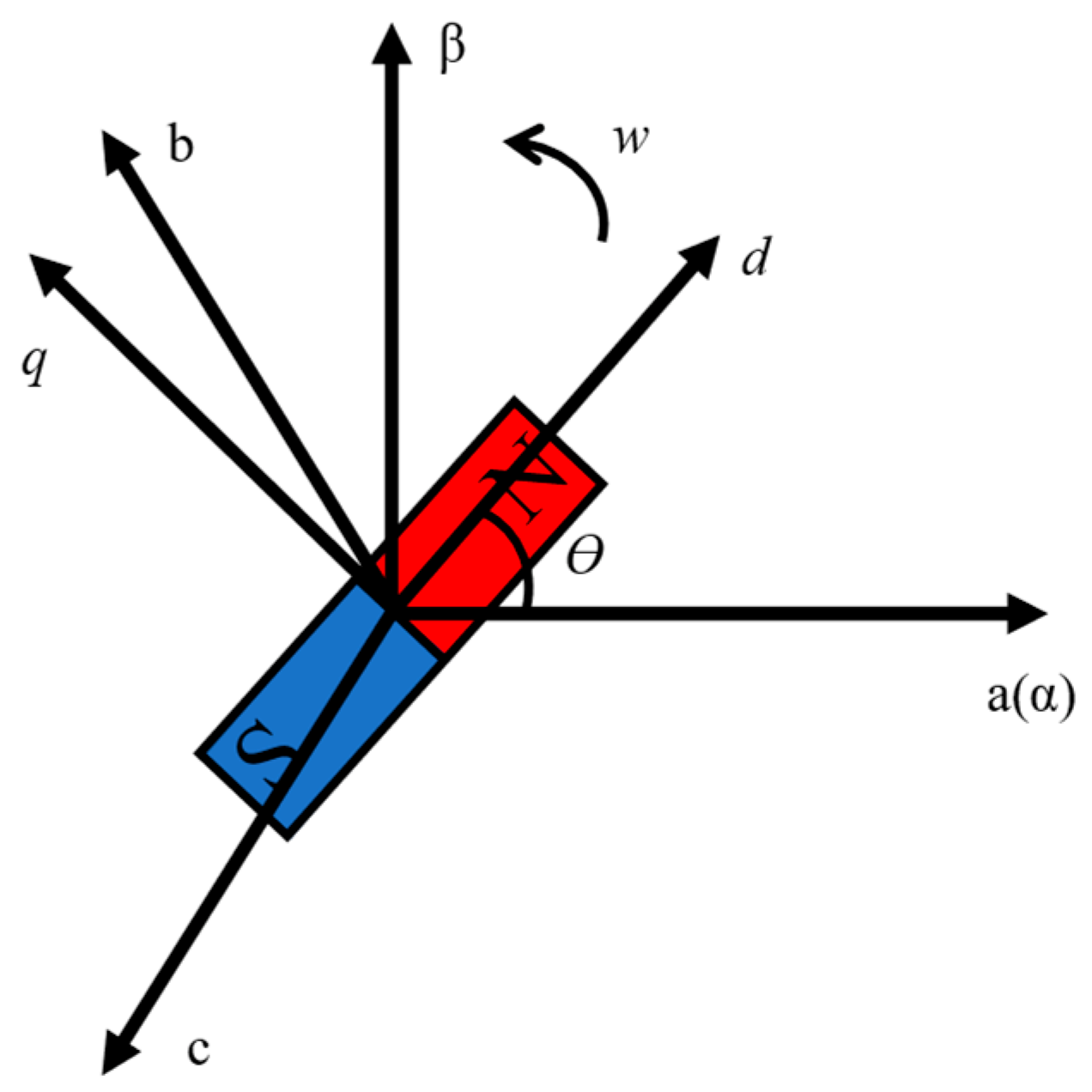
2.3.1. Mathematical Model of Permanent Magnet Synchronous Motor (PMSM)

The permanent magnet synchronous motor in the EHA system is the key part to realize the control. The hydraulic oil circuit and pump flow are controlled through the rotation of the motor. The permanent magnet synchronous motor used in the double redundancy EHA system adopts star connection. In order to simplify the description of its mathematical model, the following assumptions are made [34]:
  • The back electromotive force of the motor is sinusoidal in space.
  • The stator windings are symmetrically distributed.
  • The effects of core saturation, eddy current, hysteresis, and core loss are not considered.
A permanent magnet synchronous motor is a multivariable, strong coupling, and nonlinear complex system. The common method to establish the mathematical model is to use the axis coordinate system. A three-phase static coordinate system ( a - b - c axis), two-phase static coordinate system ( α - β axis), and two-phase rotating coordinate system ( d - q axis) are established. The relationship of the three coordinate systems is shown in Figure 4.
The flux linkage equation is [35]
φ d = L d i d + φ f φ q = L q i q
The voltage equation is
u d = R s i d + d φ d d t ω e φ q u q = R s i q + d φ q d t + ω e φ d
Substitute Formula (1) into (2):
u d = R s i d + L d d i d d t ω e L q i q u q = R s i q + L q d i q d t + ω e L d i d + ω e φ f
where, u d and u q are voltage components of rotor d - q axis; R s is the motor winding resistance; i d and i q are the current component of d - q axis; L d and L q are the equivalent inductance of d - q axis; ω e is the electrical angle of the motor and φ f is permanent magnet flux linkage.
The relationship between electrical angular velocity and mechanical angular velocity is
ω e = P n ω
where, P n is the number of poles of the motor and ω is the actual speed of the motor.
The torque equation of permanent magnet synchronous motor is
T e = 3 2 P n [ φ f i q + L d L q i d i q ]
Due to the control method of i d = 0 is used in this study, the above formula can be simplified as
T e = 3 2 P n φ f i q = C M i q
After ignoring all the lost torque of the motor, the torque balance equation of the motor is
T e = T L + B M ω + J M d ω d t
where, ω is the motor speed, J M = J m + J p is the total moment of inertia of motor and pump. B M = B m + B p is the total damping coefficient of motor and pump. C M is the electromagnetic torque coefficient. C e is the back EMF coefficient, and T L is the load torque acting on the motor shaft by the pump.
The load torque formula is
T L = p f D p 2 π
where p f = p a p b is the pressure difference between the inlet and outlet, and D p is the displacement of the hydraulic pump.

2.3.2. Mathematical Model of Hydraulic Pump

The flow equation of hydraulic pump is [36]
Q a = D p ω C ip p a p b V a β e d p a d t Q b = D p ω + C ip p a p b + V b β e d p b d t
where, Q a is the flow at the pump outlet, Q b is the flow at the pump inlet. C ip is the internal leakage coefficient of the pump. p a is the pressure at the pump outlet. p b is the pressure at the pump inlet. V a is the volume between the pump and the oil outlet. V b is the volume between the pump and the oil inlet, and β e is the effective bulk modulus of the system.

2.3.3. Mathematical Model of Hydraulic Cylinder

The flow equation of hydraulic cylinder and pipeline is [36]
Q 1 = A d x d t + V 1 + A x β e d p 1 d t + L ia p 1 p 2 Q 2 = A d x d t V 2 A x β e d p 2 d t L ia p 1 p 2
where, Q 1 is the flow in from the oil inlet pipeline of the hydraulic cylinder, Q 2 is the flow out from the oil return pipeline of the hydraulic cylinder, A is the effective pressure action area of the symmetrical cylinder, x is the piston displacement (taking the midpoint of the hydraulic cylinder stroke as the origin), V 1 is the sum of the volumes of the oil inlet pipeline and the left chamber of the hydraulic cylinder when the piston is at the midpoint of the stroke, V 2 is the sum of the volumes of the oil return pipeline and the right chamber of the hydraulic cylinder when the piston is at the midpoint of the stroke, and p 1 is the pressure of the left chamber of the hydraulic cylinder, p 2 is the pressure in the right chamber of the hydraulic cylinder and L ia is the leakage coefficient in the hydraulic cylinder.
Regardless of the pressure drop of the pipeline connecting the hydraulic pump and the hydraulic cylinder, there are
d p a d t d p 1 d t d p b d t d p 2 d t Q a Q 1 Q b Q 2
The load force balance equation of hydraulic cylinder is
A p 1 p 2 = m t d 2 x d t 2 + B t d x d t + K t x + F L
where, A is the effective area of the hydraulic cylinder, m t is the total inertia mass of the piston and the load converted to the piston, B t is the viscous damping coefficient, K t is the load spring stiffness, and F L is the external load force.
Take the state variables X = i d i q w p 1 p 2 x x ˙ T such as current, speed, pressure, and displacement of left and right chambers of hydraulic cylinder, and establish the state space model of EHA system as follows:
X ˙ 1 = 1 L d ( u d + L q P n X 2 X 3 R s X 1 ) X ˙ 2 = 1 L q ( u q L d P n X 1 X 3 R s X 2 P n φ f X 3 ) X ˙ 3 = 1 J M [ C M X 2 D p 2 π X 4 X 5 B M X 3 ] X ˙ 4 = β e V 1 + V a + A X 6 [ D p X 3 C ip + L ia X 4 X 5 A X 7 ] X ˙ 5 = β e V 2 + V b A X 6 [ D p X 3 C ip + L ia X 4 X 5 + A X 7 ] X ˙ 6 = X 7 X ˙ 7 = 1 m t [ A X 4 X 5 B t X 7 K t X 6 F L ]
The state space equation is the basis of the fault diagnosis based on the analytical model. Next, the model is built with modeling and programming language.

2.4. Establishment and Verification of Double Redundancy EHA Model

2.4.1. Main Parameters of Double Redundancy EHA System

The parameters of the whole double redundancy EHA system are listed as shown in Table 3.

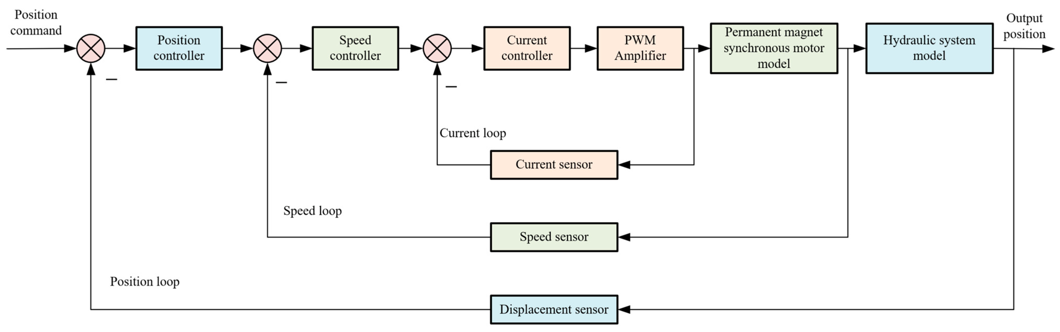
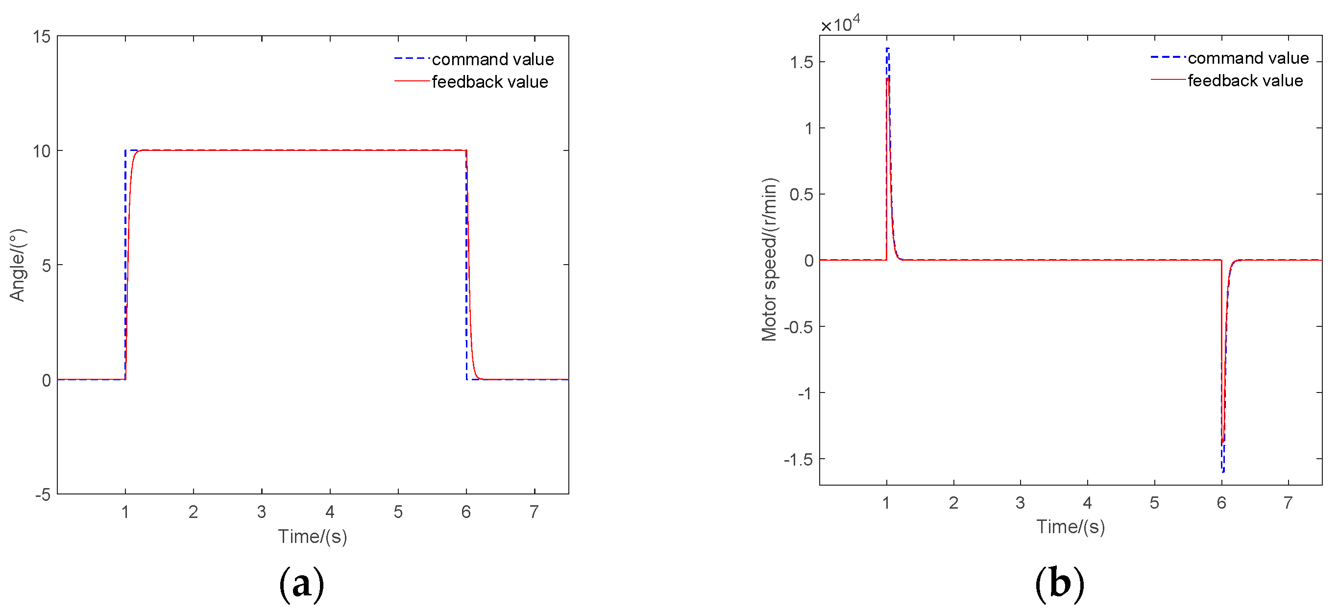
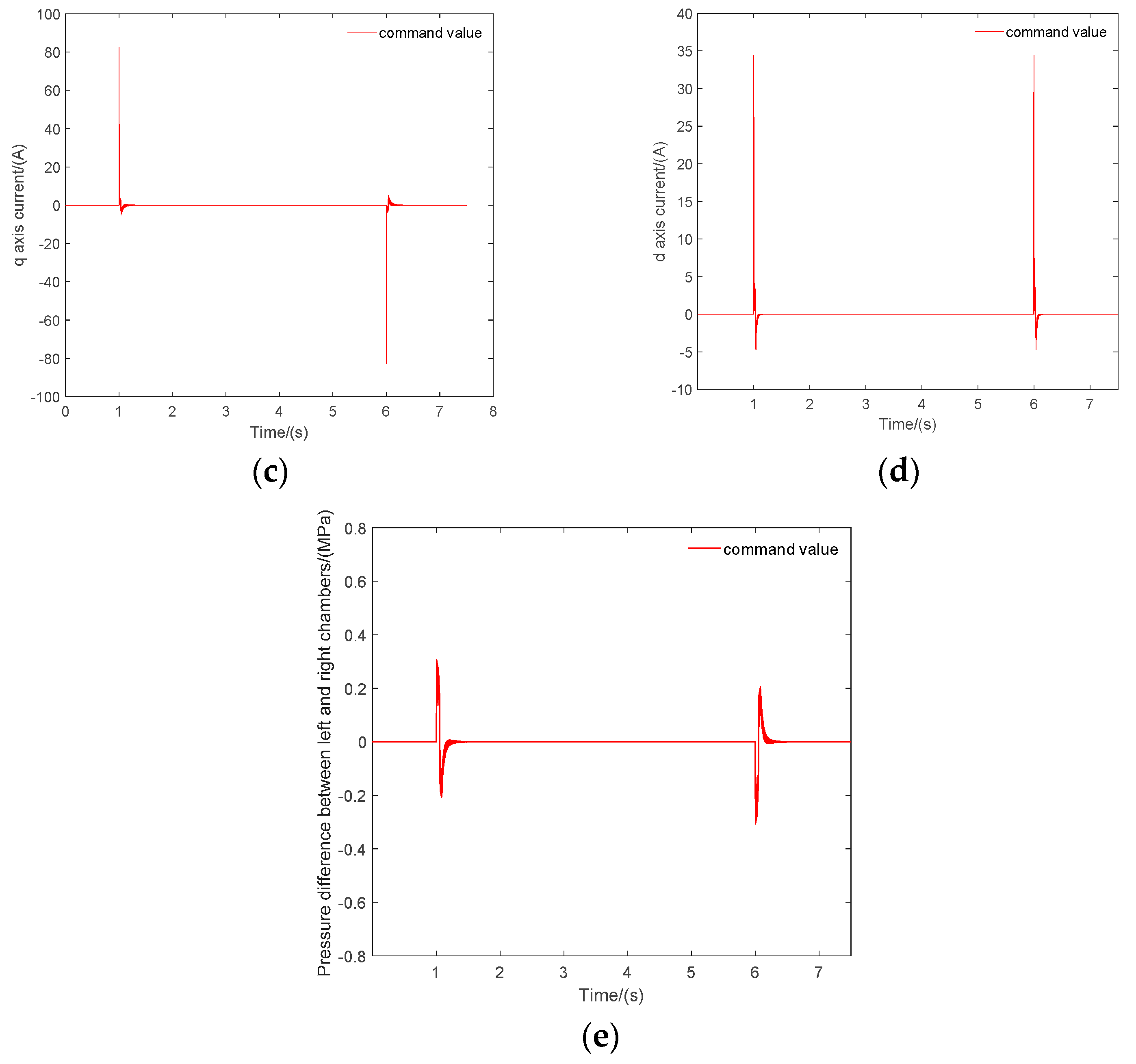
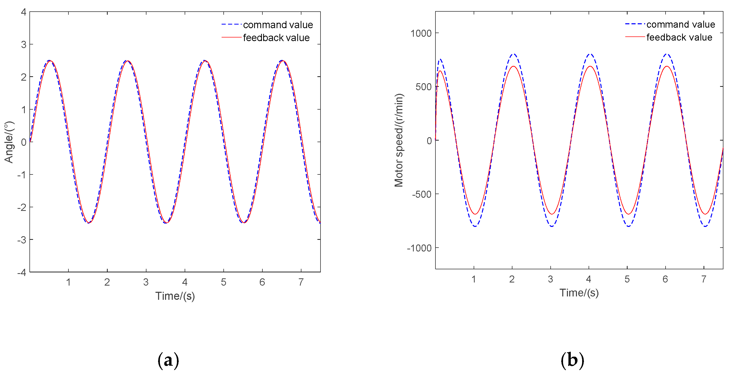
2.4.2. Simulation of double redundancy EHA system

According to the actual double redundancy EHA system parameters and the above EHA state space equation, the simulation model is established as shown in Figure 5.
The decoupling control of i d * = 0 is used in this model [37], where i d * is the given expected value of i d . The whole system adopts the three-loops control of position loop, speed loop and current loop. Comparing the displacement feedback with the displacement command is the position loop. The speed command signal is formed through PID adjustment and compared with the speed feedback signal to form a speed loop; Then the stator armature q axis voltage command signal is formed by PID controller, which is combined with the command signal and input into the model of permanent magnet synchronous motor to obtain the stator armature current d axis component value i d and q axis component value i q .
In this simulation model, the simulation step size is reduced as much as possible to reduce the fluctuation of each state simulation curve. The integration method uses the Runge–Kutta integration method, which is more accurate than the commonly used Euler method. Generally speaking, the shorter the simulation step, the more accurate the integration, and the better the simulation effect. However, the simulation step cannot be as small as possible. Considering the DSP development later, because the running program has a certain physical time, in order to maintain its prediction effect, the simulation time for one integral calculation must be greater than the physical time for the program to run. After measurement, the time for the program to run once is 0.02 ms. Therefore, the Runge–Kutta integral method with a fixed step length of 0.1 ms is used for simulation integration. Traditionally, when we build a double redundancy EHA system model for fault diagnosis, the input of the system is only a position command. In this study, because we set up two cavity pressure sensors in the hardware, we can calculate the load force in real time through the pressure difference, and introduce it into the model calculation to make the model calculation more accurate. The connection mode between the fault-tolerant controller and the whole system is shown in Figure 6.
Applying step signals with different amplitudes and sinusoidal signals with different frequencies and amplitudes, then comparing them with the corresponding measured signals, we adjust PID parameters to make sure that the simulation state of double redundancy EHA system is closer to operating state of prototype. The change curve of displacement, speed, current, and pressure under 10-degree step and 2.5-degree position commands are listed as shown in the figures below. In this paper, the displacement command signal is expressed by the swing angle. When the actual system has problems, the signal will change greatly. The control error between the process value and the setpoint value can be ignored and will not affect the accuracy of fault diagnosis.
It can be seen from Figure 7a,b and Figure 8a,b that, under step and sinusoidal command signals, displacement feedback and speed feedback can accurately fit with displacement and speed command signals. In Figure 7c–e and Figure 8c–e, q axis current, d axis current, and pressure difference between the left and right chambers are also not different from the measured signals, and the fluctuation of pressure difference between the left and right chambers of the hydraulic cylinder is within a reasonable range. Therefore, this model can accurately simulate the operation state of an actual EHA system under different command signals, and can be used in PFDM.

2.4.3. Establishment of Model in C Language

After the accurate double redundancy EHA model is established, the C language program is written according to the mathematical model of EHA system in Section 2.3 and verified in Visual Studio. Firstly, the differential equation is discretized, and the integration step is calculated at 0.1 ms step length as in Section 2.4. The integration method is the same as above. The standard fourth-order Runge–Kutta integration method is used, and its main formula is as follows:
y n + 1 = y n + h 6 ( K 1 + 2 K 2 + 2 K 3 + K 4 ) K 1 = f ( x n , y n ) K 2 = f ( x n + h 2 , y n + h 2 K 1 ) K 3 = f ( x n + h 2 , y n + h 2 K 2 ) K 4 = f ( x n + h , y n + h K 3 )
where, h is the integration step size, K 1 , K 2 , K 3 and K 4 are the four slopes of the fourth-order Runge–Kutta method. At the same time, when choosing the integral method, the accuracy of the Euler method cannot meet the requirements. As shown in Figure 9, under the Euler method, the maximum value of the motor speed command signal reaches 21,000 rpm, far more than 6018.64 rpm of the maximum value of the feedback signal, so the Runge–Kutta method is finally selected.
The five state variables of displacement, speed, q axis current, d axis current, and pressure difference between the left and right chambers of the hydraulic cylinder are integrated and calculated respectively, and the iterative calculation is carried out continuously according to the displacement command. Finally, all the calculated points of the five state quantities at each time are compared with the measured signals, as shown in Figure 10 and Figure 11.
As shown in Figure 10 and Figure 11, under the 10-degree step command under no-load conditions and the 2.5-degree 1 Hz to 11 Hz frequency change command under load conditions, it can be observed that the simulation data and the measured data are generally more fitting. However, affected by the actual environment of the prototype, some measurement points may deviate from the normal analog values, and the influence of these abnormal values can be eliminated by subsequent signal processing. The simulation results show that the model program can be used in the design of actual monitoring software. In addition to the conventional position command, the load pressure is introduced as input to the model to simulate the load characteristics and ensure the accuracy of the model prediction.
After taking the load condition as the input of the model, the simulation data under different working conditions are set and compared with the actual data. The results are shown in Table 4. The model performs well under different working conditions, and the error is less than 5%—even less than 0.03% when under no load—which verifies the accuracy of the model.

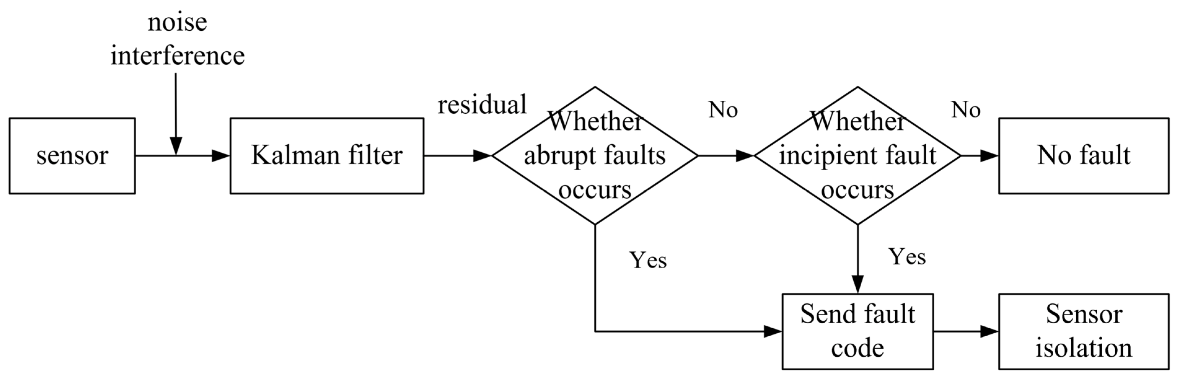
2.4.4. Sensor Fault Diagnosis Based on Kalman Filter

Sensor faults can be divided into incipient fault and abrupt fault according to the degree of fault occurrence. Abrupt fault generally refers to the fault caused by structural damage, strong pulse signal interference, and other issues, which generally causes the measured value amplitude of the sensor to be large and the change is very sudden. Incipient fault will generally lead to the phenomenon of small amplitude and slow change of signal, and the sensor will have incipient fault due to aging of components and other reasons. We will diagnose the sensor from the above two situations. In this study, the diagnosis process of sensor abrupt fault and incipient fault is shown in Figure 12.
When diagnosing sensor faults, Kalman filtering is continuously performed on the collected values of each sensor. If the difference between the actual measured value of the sensor and the estimated value of the Kalman filter is too large at a certain time, exceeding the abrupt fault threshold of the current sensor, as shown in Figure 13a, the current sensor is considered to have an abrupt fault if the collected value of the current sensor and the estimated value of the Kalman filter jump between 0.5 s and 0.6 s. A fault code shall be sent to isolate the fault of the sensor.
As shown in Figure 13b, the incipient fault of the sensor cannot be judged simply by the threshold value. Therefore, one point is extracted from the Kalman estimation value of the sensor every 0.1 s. It is judged whether the difference between these estimated values is too large. Therefore, if the difference is too large and there is an obvious change trend according to the time arrangement, the sensor is considered to have an incipient fault, and the sensor fault code is sent and the fault is isolated.
At this stage, the faults of current sensors, booster tank pressure sensor, temperature sensors, hydraulic cylinder pressure sensors, and other sensors can be judged. Because of the redundant setting of the displacement sensor in this paper, the two displacement sensors can check each other. At the same time, if there is a proportional relationship between the collected value of the speed sensor and the collected value of the displacement sensor when the system is normal, the fault diagnosis method of the two can be diagnosed through the EHA system logic.

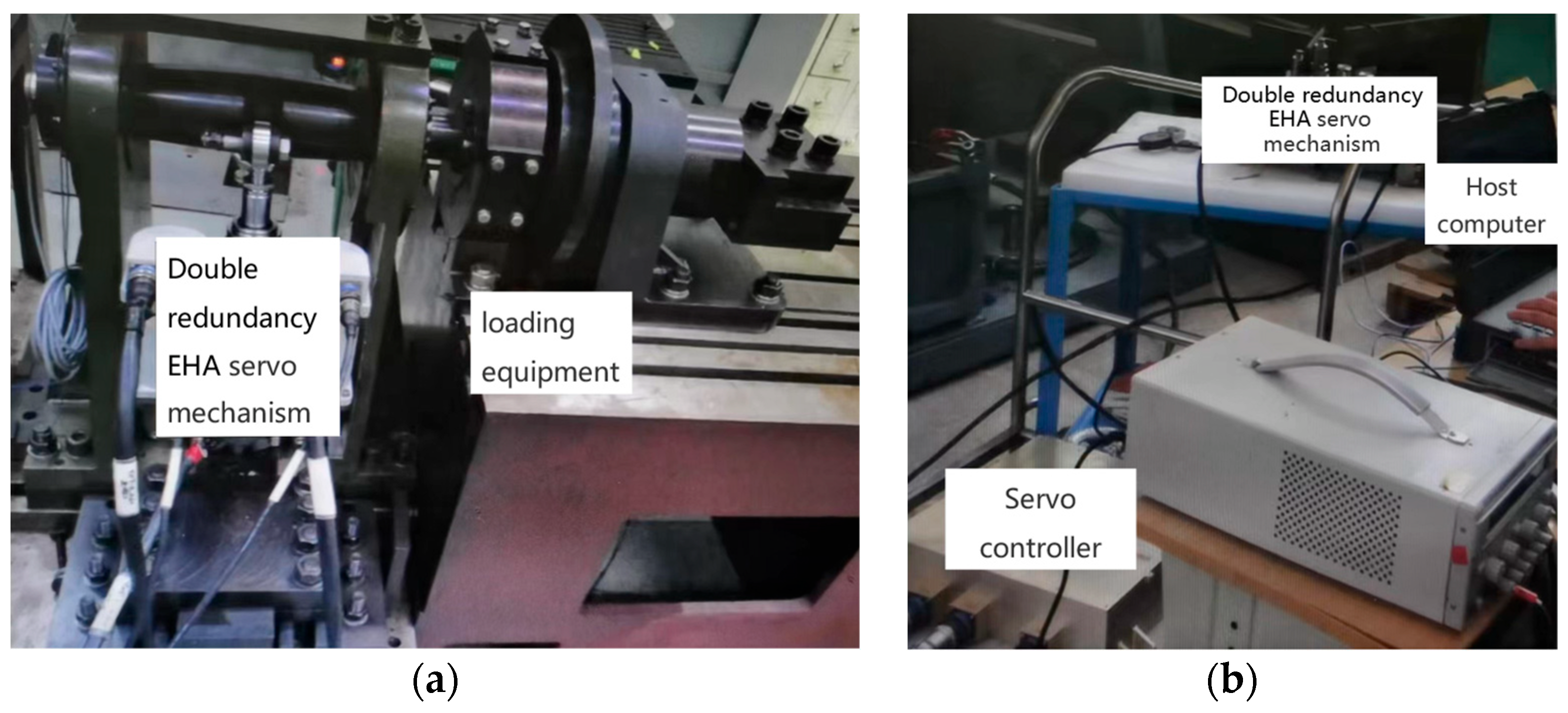
3. Experimental Results of Physical Prototype

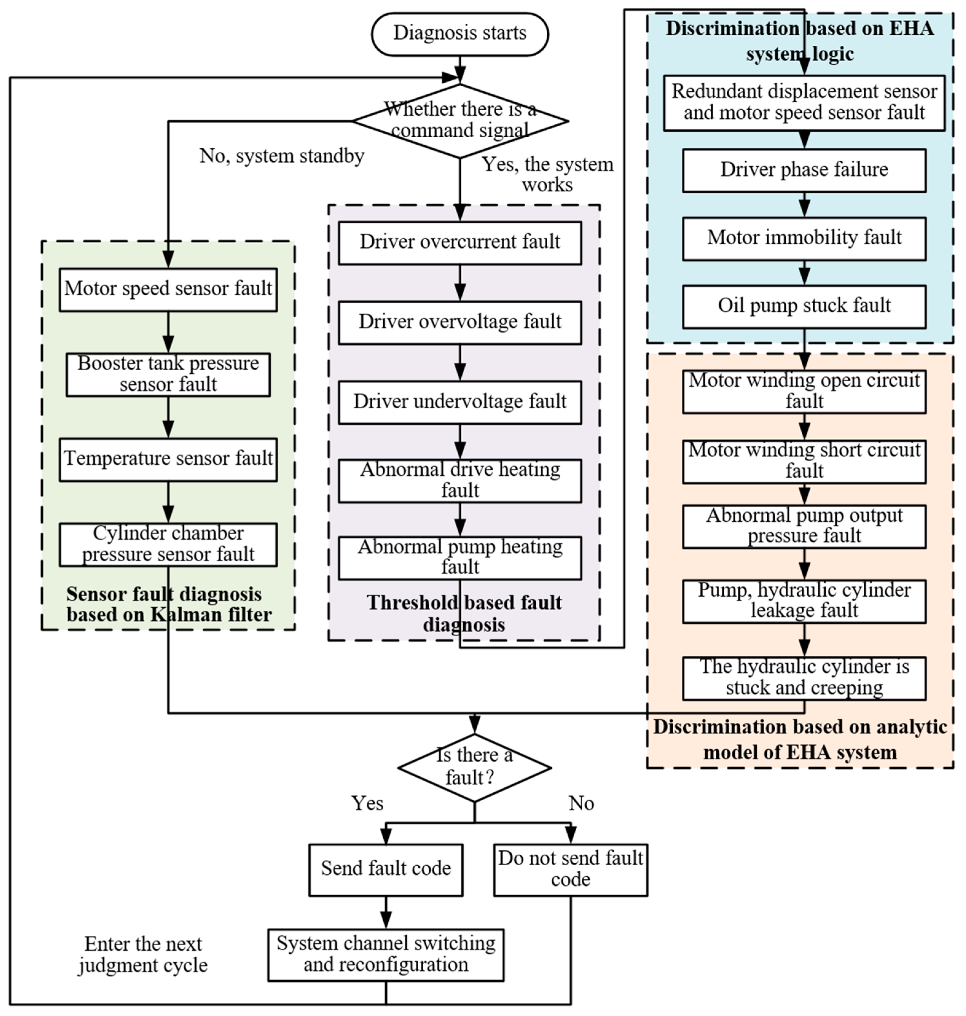
3.1. Realization of PFDM

The fault-tolerant controller of PFDM is based on TMS320F28379D dual-core DSP chip of TI company. The whole double redundancy EHA control system is realized by two DSPs in hardware. The servo controller is mainly responsible for the closed-loop servo control of the currently running EHA channel and the channel switching after receiving the fault code. The monitor is mainly responsible for real-time monitoring the operation status of the system, finding and diagnosing system faults in time. Monitoring DSP is the control core of the whole system. It needs to complete the data acquisition, filtering, and A/D conversion of the sensor, and communicate with the servo controller DSP to obtain the command information of the servo controller. The fault monitoring and diagnosis are carried out according to all collected data.
As shown in Figure 14, it is the specific process of the PFDM proposed for the entire EHA system. At the beginning of diagnosis, the fault-tolerant controller first detects the position command signal. If the command signal is not detected, the system is in standby state. The sensor fault diagnosis of the Kalman filter is carried out on the collected signals of each sensor. The diagnoses of fault types include electric flow sensor fault, booster tank pressure sensor fault, temperature sensor fault, and hydraulic cylinder two-chamber pressure sensor fault. At this stage, we can preliminarily screen out whether each sensor is faulty.
If the servo controller receives the position command signal, the system is in the working state. At this time, it is considered that—after the sensor fault diagnosis in the standby phase—the current sensor, booster tank pressure sensor, temperature sensor, and pressure sensor in the two chambers of the hydraulic cylinder are in good condition. Next, the fault discrimination based on the threshold, EHA system logic, and analytical model is carried out. When collecting signals and collecting sensor data during double redundancy EHA system operation, some filtering methods are often used to eliminate the interference of abnormal values in order to reduce interference. The field layout of the whole fault injection experiment section is shown in Figure 15.
For the three diagnostic steps of PFDM, fault injection and simulation experiments are carried out based on threshold, logic, and analysis models. The fault codes reported after fault diagnosis have been listed in Table 2. In the field of fault diagnosis, fault injection is a thorny problem. Since the experimental object of this study is the double redundancy EHA prototype, which has high destruction cost and is difficult to inject from hardware, software injection is adopted for fault experiments. The experimental results are as follows.

3.2. Fault Experiment Based on Threshold

In the stage of threshold-based diagnosis, because the injection principle of various faults is similar to the experimental effect, the experimental process of threshold judgment is illustrated by taking the driver overvoltage fault as an example.
The normal bus voltage of the permanent magnet synchronous motor driver used in this experiment is 270 V. In order to simulate the driver overvoltage, the voltage value is increased to 300 V. The fault diagnosis algorithm collects the bus voltage value 10 consecutive times. If they all exceed the normal bus voltage threshold (290 V), driver overvoltage fault is considered as having occurred. As shown in Figure 15, after fault injection, fault code 3 is reported after a judgment cycle of 4 ms. The same method is used for all kinds of sensors no output value or abnormal output value fault, driver overcurrent fault (fault code 2), driver undervoltage fault (fault code 4), abnormal driver heating fault (fault code 5), and abnormal pump heating fault (fault code 19). According to the data records transmitted between the CAN bus and the upper computer, the fault code change diagram is drawn, as shown in Figure 16.

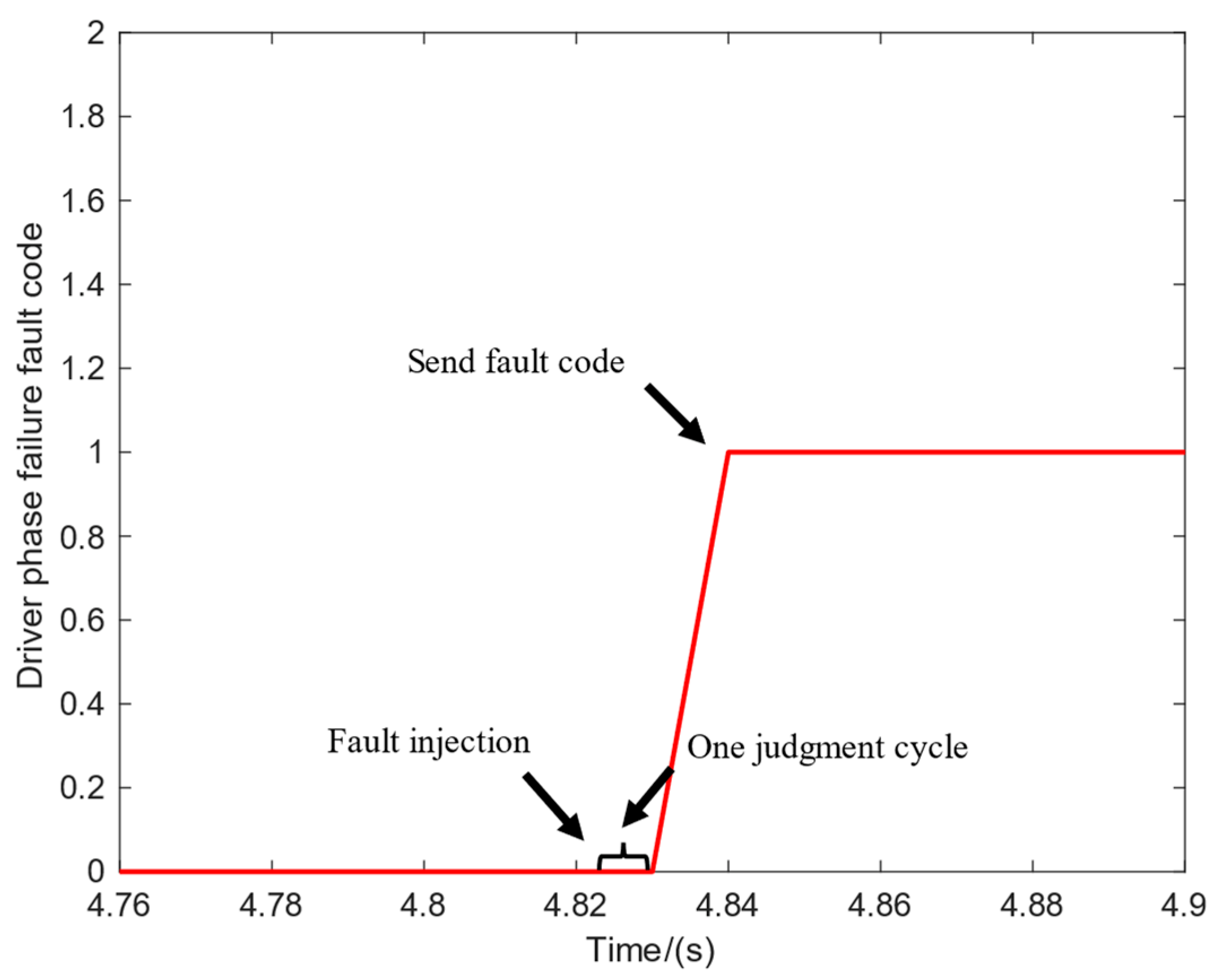
3.3. Fault Experiment Based on Logical Judgment

Taking the driver phase failure as an example, the current sensor is sampled according to the principles listed in Section 2.2. The collected value of one current sensor is set to 0, and the other two phases collect normally. It can be judged that the fault current of the driver exceeds the phase loss threshold of the driver, and the fault code 1 is reported, as shown in Figure 17. Similarly, the method based on EHA system logic can also be used to judge motor immobility fault (Fault code 6) and oil pump stuck fault (Fault code 17).

3.4. Fault Experiment Based on Double Redundancy EHA Mathematical Model

After the first two steps of filtration, collect the position feedback, q axis current, d axis current, speed value, and two chamber pressure values in real time, initialize the model calculation program, take the displacement command at the moment as the output value of the whole model, and take the abnormal pump output pressure fault as an example. The calculation step of the model is 0.1 ms, 40 iterative calculations are carried out, and the state quantities after 4ms are calculated and compared with the collected values at this time. As shown in Figure 18, the deviation is injected into the speed value at the time of 5.306 s, and the fault code 16 is reported at 5.31 s. For motor winding open circuit fault (Fault code 7), motor winding short circuit fault (Fault code 8), pump leakage fault (Fault code 18), hydraulic cylinder stuck fault (Fault code 20), hydraulic cylinder leakage fault (Fault code 21), and hydraulic cylinder creeping fault (Fault code 22), the method based on a double-redundancy EHA system mathematical model will be used to judge in the same way.
After the debugging and verification of the physical prototype, PFDM can diagnose each fault accurately and effectively, and can be applied to the detection of a double redundancy EHA system.

3.5. Fault Isolation and System Reconfiguration

During the experiment, fault injection from software is adopted in order to prevent the double redundancy EHA prototype from being damaged, such as control and model calculation of a signal superimposed with ramp signal or offset signal. At this time, the residual generated by actual measurement and simulation calculation is used for residual evaluation to determine whether there is a fault.
In case of irreversible failure of the system, the controller will quickly cease operation of the main channel. In addition, the controller sends a signal to make the solenoid valve switch channels and uses the standby channel to ensure the normal operation of the flight control system so that the aircraft can quickly resume normal operation. During the switching process, the accurate current, speed, displacement and other state variables calculated by the EHA system model in the fault-tolerant controller will be directly used as control commands to control the EHA system of the standby channel, so that the standby channel will continue the movement position and state before the failure of the main channel, thereby ensuring the normal operation of the system.

4. Conclusions

PFDM based on an analytical model is applied in fault diagnosis, and an accurate EHA model is established according to the measured data. Combining the fault diagnosis technology based on system analytical model, signal processing, threshold, and EHA system logic, an innovative fault diagnosis method is proposed, which is finally applied to the development of double redundancy EHA system monitoring software. Experiments show that PFDM can monitor and detect the faults of double redundancy EHA system, and can detect and identify some sensor faults and key equipment faults at the system level at the same time. PFDM uses an accurate model with an error of less than 5%, and it can accurately diagnose up to 22 kinds of faults. Its advantages are as follows:
  • It overcomes the limitation of other fault diagnosis methods with fewer programs and easier on-line diagnosis.
  • It does not depend on specific equipment and is easier to update and maintain. The state variables of the model can be updated in real time according to the parameter changes of the actual system, so as to make the fault diagnosis results more accurate.
  • PFDM has more faults than other common diagnosis methods. It can distinguish and locate faults that are difficult to judge in the system more accurately, and has strong engineering applicability.
  • PFDM is combined with the traditional actuator modeling and simulation method, which has stronger reliability.
  • Combined with redundancy technology, it can accurately locate sensor faults and diagnose faults accurately.
  • PFDM can separate sensor faults from double redundancy EHA system faults, avoiding the disadvantage of traditional data analysis methods.
In this study, we combine the model-based fault diagnosis method with the signal processing method to diagnose incipient fault and abrupt fault separately. The pressure difference between the two chambers of the hydraulic cylinder is creatively introduced into the real-time model calculation to make the model more accurate. At the same time, the main faults of the whole EHA system are sorted out, and the diagnosis is carried out according to the principle of diagnosis and the degree of difficulty, and PFDM is proposed. It cannot only distinguish sensor faults from equipment faults, but also locate different faults, which effectively improves the reliability of aircraft control systems.
In the future, there will be increasing numbers of fault diagnosis methods for flight control systems and electrostatic actuators. Combining the fault diagnosis technology based on analysis model with the new technology based on signal processing, data driving, expert systems, and neural networks, overcoming their shortcomings and combining their advantages will be the development direction of fault diagnosis of electro-hydraulic actuators. At the same time, in order to improve the safety and reliability of aircraft, EHA systems with different redundancies will be increasingly applied to flight control systems in the future.

Author Contributions

Writing, D.-A.Z.; Methodology, H.-T.Q.; Software, D.L.; Validation, D.-A.Z. and X.L. All authors have read and agreed to the published version of the manuscript.

Funding

This research received no external funding.

Data Availability Statement

Not applicable.

Conflicts of Interest

The authors declare no conflict of interest.

References

  1. Li, L.; Wang, M.; Yang, R.; Fu, Y.; Zhu, D. Adaptive damping variable sliding mode control for an electrohydrostatic actuator. Actuators 2021, 10, 83. [Google Scholar] [CrossRef]
  2. David, E.B. An assessment of developing dual use electric actuation technologies for military aircraft and commercial application. In Proceedings of the IECEC-97 Proceedings of the Thirty-Second Intersociety Energy Conversion Engineering Conference (Cat. No.97CH6203), Honolulu, HI, USA, 27 July–1 August 1997; pp. 716–721. [Google Scholar]
  3. Zhang, H.F.; Xie, J.; Guan, W.L.; Zhang, L. Modeling and simulation of EHA system based on fuzzy adaptive PID control. In Proceedings of the 2017 IEEE 3rd Information Technology and Mechatronics Engineering Conference (ITOEC), Chongqing, China, 3–5 October 2017; pp. 750–753. [Google Scholar]
  4. Yu, B.; Wu, S.; Jiao, Z.; Shang, Y. Multi-objective optimization design of an electrohydrostatic actuator based on a particle swarm optimization algorithm and an analytic hierarchy process. Energies 2018, 11, 2426. [Google Scholar] [CrossRef]
  5. Liu, X.X.; Zhang, W.G.; Li, G.W. Redundancy design technology of fly by wire flight control system. J. Aircr. design. Commun. 2006, 1, 35–38. (In Chinese) [Google Scholar]
  6. Zhao, J.Y.; Hu, J.; Yao, J.Y.; Zhou, H.B.; Wang, J.L.; Cao, M.M. EHA fault diagnosis and fault tolerant control based on adaptive neural network robust observer. J. Beijing Univ. Aeronaut. Astronaut. 2022, 1–16. (In Chinese) [Google Scholar] [CrossRef]
  7. Philippe, G. Oscillatory failure case detection in the A380 electrical flight control system by analytical redundancy. Control Eng. Pract. 2010, 18, 1110–1119. [Google Scholar]
  8. Chi, C.Z.; Zhang, W.G.; Liu, X.X. A method for comprehensive diagnosis of sensors of flight control system using analytical redundancy. In Proceedings of the 2010 International Conference on Electrical and Control Engineering, Washington, DC, USA, 25–27 June 2010; pp. 4892–4895. [Google Scholar]
  9. Stephen, C.J.; Gavin, D.J.; David, D. Flight test experience with an electromechanical actuator on the F-18 Systems Research Aircraft. In Proceedings of the 19th Digital Avionics Systems Conference. Proceedings (Cat. No.00CH37126), Philadelphia, PA, USA, 7–13 October 2000; Volume 1, p. 2E3/1-2E310. [Google Scholar]
  10. Navarro, R. Performance of an Electro-Hydrostatic Actuator on the F-18 Systems Research Aircraft; National Aeronautics and Space Administration, Dryden Flight Research Center: Edwards, CA, USA, 1997. [Google Scholar]
  11. Liu, H.; Peng, S.; Jiang, B. Fault detection, diagnosis, and fault tolerant control with flight applications. J. Frankl. Inst. 2013, 350, 2371–2372. [Google Scholar] [CrossRef]
  12. Isermann, R.; Balle, P. Trends in the application of model-based fault diagnosis of technical processes. Control Eng. Pract. 1997, 5, 709–719. [Google Scholar] [CrossRef]
  13. Wlamir, V.; Luiz, R.; Takashi, Y. Electro hydraulic servovalve health monitoring using fading extended Kalman filter. In Proceedings of the 2015 IEEE Conference on Prognostics and Health Management (PHM), Austin, TX, USA, 22–25 June 2015; pp. 1–6. [Google Scholar]
  14. Gao, Z.; Cecati, C.; Steven, X.D. A Survey of Fault Diagnosis and Fault-Tolerant Techniques—Part I: Fault Diagnosis with Model-Based and Signal-Based Approaches. IEEE Trans. Ind. Electron. 2015, 62, 3757–3767. [Google Scholar] [CrossRef]
  15. Yu, Y.; Denchai, W.; Yu, D. A review of fault detection and diagnosis methodologies on air-handling units. Energy Build. 2014, 82, 550–562. [Google Scholar] [CrossRef]
  16. Davor, L.; Vladimir, K. Fault diagnosis of a hydraulic actuator using neural network. In Proceedings of the IEEE International Conference on Industrial Technology, Maribor, Slovenia, 10–12 December 2003; pp. 108–111. [Google Scholar]
  17. Andrea, M.; Giovanni, J. Prognostic and health management system for fly-by-wire electro-hydraulic servo actuators for detection and tracking of actuator faults. Procedia CIRP 2017, 59, 116–121. [Google Scholar]
  18. Arellano-Espitia, F.; Delgado-Prieto, M.; Martinez-Viol, V.; Saucedo-Dorantes, J.J.; Osornio-Rios, R.A. Deep-learning-based methodology for fault diagnosis in electromechanical systems. Sensors 2020, 20, 3949. [Google Scholar] [CrossRef]
  19. Liu, L.; Wang, Z.; Yao, X.; Zhang, H. Echo state networks based data-driven adaptive fault tolerant control with its application to electromechanical system. IEEE/ASME Trans. Mechatron. 2018, 23, 1372–1382. [Google Scholar] [CrossRef]
  20. Wang, J.; Miao, J.; Wang, J.; Yang, F.; Tsui, K.L.; Miao, Q. Fault diagnosis of electrohydraulic actuator based on multiple source signals: An experimental investigation. Neurocomputing 2020, 417, 224–238. [Google Scholar] [CrossRef]
  21. Chinniah, Y. Fault Detection in the Electrohydraulic Actuator Using Extended Kalman Filter; University of Saskatchewan: Saskatoon, SK, Canada, 2004. [Google Scholar]
  22. Chinniah, Y.; Burton, R.; Habibi, S. Failure monitoring in a high performance hydrostatic actuation system using the extended Kalman filter. Mechatronics 2006, 16, 643–653. [Google Scholar] [CrossRef]
  23. Chinniah, Y.; Burton, R.; Habibi, S.; Sampson, E. Identification of the nonlinear friction characteristics in a hydraulic actuator using the extended Kalman filter. Trans. Can. Soc. Mech. Eng. 2008, 32, 121–136. [Google Scholar] [CrossRef]
  24. Marzat, J.; Piet-Lahanier, H.; Damongeot, F.; Walter, E. Model-based fault diagnosis for aerospace systems: A survey. Proc. Inst. Mech. Eng. Part G J. Aerosp. Eng. 2012, 226, 1329–1360. [Google Scholar] [CrossRef]
  25. Isermann, R. Model-based fault-detection and diagnosis—Status and applications. IFAC Proc. Vol. 2005, 37, 46–60. [Google Scholar] [CrossRef]
  26. Dai, X.W.; Gao, Z.W. From model, signal to knowledge: A data-driven perspective of fault detection and diagnosis. IEEE Trans. Ind. Inform. 2013, 9, 2226–2238. [Google Scholar] [CrossRef]
  27. Li, K.; Lv, Z.; Lu, K.; Yu, P. Thermal-hydraulic Modeling and Simulation of the Hydraulic System based on the Electro-hydrostatic Actuator. Procedia Eng. 2014, 80, 272–281. [Google Scholar] [CrossRef] [Green Version]
  28. Wiegand, C. F-35 Air Vehicle Technology Overview. In Proceedings of the 2018 Aviation Technology, Integration, and Operations Conference, Atlanta, Georgia, 25–29 June 2018. [Google Scholar]
  29. Lei, Z.F.; Qin, L.J.; Wu, X.D.; Jin, W.; Wang, C.X. Research on fault diagnosis method of electro-hydrostatic actuator. Shock. Vib. 2021, 2021, 6688420. [Google Scholar]
  30. Wang, Y.Y.; Chen, H.J.; Yang, X.G.; Sun, Q.; Qiao, T.T.; Zhang, K. Fault diagnosis method of underwater control module hydraulic system based on decision tree. Mar. Eng. 2022, 44, 154–164. (In Chinese) [Google Scholar]
  31. Fu, Y.L.; Wang, L.J.; Qi, H.T.; Liu, H.S. Fault diagnosis and management of electro-hydrostatic actuator. Mach. Tools Hydraul. 2010, 38, 120–124. (In Chinese) [Google Scholar]
  32. Cai, Z.N. Analysis of fault types and diagnosis Countermeasures in mechanical hydraulic system. Value Eng. 2018, 37, 158–159. (In Chinese) [Google Scholar]
  33. Li, Q.Z. Talking about fault types and diagnosis Countermeasures in mechanical hydraulic system. Sci. Technol. Inf. 2016, 14, 116–117. (In Chinese) [Google Scholar]
  34. Li, Y.; Zhou, J.M. Simulation of electric-hydrostatic actuator driven by permanent magnet synchronous motor. J. Nanchang Hangkong Univ. (Nat. Sci.) 2014, 28, 38–44. (In Chinese) [Google Scholar]
  35. Kamalaselvan, A.; Prakash, S.L. Modeling simulation and analysis of closed loop speed control of PMSM drive system. In Proceedings of the 2014 International Conference on Circuits, Power and Computing Technologies, Nagercoil, India, 20–21 March 2014; pp. 692–697. [Google Scholar]
  36. Xia, L.Q.; Zhu, M.J.; Hu, Y.X.; Yang, Y.K. Modeling and simulation analysis of EHA actuator. Mach. Tools Hydraul. 2021, 49, 136–142. (In Chinese) [Google Scholar]
  37. Ge, Y.W.; Zhu, W.L.; Liu, J.H.; Deng, W.X.; Yao, J.Y. Refined Modeling and Characteristic Analysis of Electro-hydrostatic Actuator. J. Mech. Eng. 2021, 57, 66–73. (In Chinese) [Google Scholar]
Figure 1. Design method of PFDM.
Actuators 11 00264 g001
Figure 2. EHA with different redundancy. (a) Single redundancy EHA physical prototype [27]; (b) Double redundancy EHA physical prototype applied on F-35 [28].
Actuators 11 00264 g002
Figure 3. Structure diagram of the double redundancy EHA system.
Actuators 11 00264 g003
Figure 4. Relationship diagram between vectors in a spatial coordinate system.
Actuators 11 00264 g004
Figure 5. Simulation diagram of double redundancy EHA system.
Actuators 11 00264 g005
Figure 6. Schematic diagram of the EHA system multi-input fault tolerant controller.
Actuators 11 00264 g006
Figure 7. MATLAB/Simulink simulation diagram under 10-degree step signal. (a) Angle comparison; (b) Motor speed comparison; (c) q axis current; (d) d axis current; (e) Pressure difference between the left and right chambers of the hydraulic cylinder.
Actuators 11 00264 g007aActuators 11 00264 g007b
Figure 8. MATLAB/Simulink simulation diagram under 2.5-degree 0.5 Hz sinusoidal signal. (a) Angle comparison; (b) Motor speed comparison; (c) q axis current; (d) d axis current; (e) Pressure difference between the left and right chambers of the hydraulic cylinder.
Actuators 11 00264 g008aActuators 11 00264 g008b
Figure 9. Comparison between Euler simulation results and measured data.
Actuators 11 00264 g009
Figure 10. Comparison between simulation data and actual data of each variable of no-load 10-degree step command. (a) Angle comparison; (b) Motor speed comparison; (c) q axis current; (d) d axis current; (e) Pressure difference between the left and right chambers of the hydraulic cylinder.
Actuators 11 00264 g010aActuators 11 00264 g010b
Figure 11. Comparison between simulation data and actual data of each variable of load 2.5-degree 1 Hz to 11 Hz command. (a) Angle comparison; (b) Motor speed comparison; (c) q axis current; (d) d axis current; (e) Pressure difference between the left and right chambers of the hydraulic cylinder.
Actuators 11 00264 g011aActuators 11 00264 g011b
Figure 12. Flow chart of sensor fault diagnosis.
Actuators 11 00264 g012
Figure 13. Kalman filter diagram of current sensor fault. (a) Kalman filter diagram of current sensor abrupt fault; (b) Kalman filter diagram of current sensor incipient fault.
Actuators 11 00264 g013
Figure 14. PFDM composition architecture.
Actuators 11 00264 g014
Figure 15. Testbench used for the fault injection experiments. (a) Load table test site; (b) Software and hardware debugging site.
Actuators 11 00264 g015
Figure 16. Driver overvoltage fault code diagram.
Actuators 11 00264 g016
Figure 17. Fault code diagram of driver phase failure.
Actuators 11 00264 g017
Figure 18. Fault code diagram of abnormal pump output pressure fault.
Actuators 11 00264 g018
Table 1. Sensor layout position.
Sensor NameQuantityLayout Location
Temperature sensor6Driver circuit board and hydraulic pump inlet and outlet
Current sensor5Permanent magnet synchronous motor and power bus circuit
Pressure sensor3At the booster oil tank and in the oil inlet and outlet of hydraulic cylinder
Displacement sensor2Both ends of hydraulic cylinder
Booster tank pressure sensor1In booster tank
Speed sensor2Permanent magnet synchronous motor
Voltage sensor1power bus circuit
Table 2. Double redundancy EHA fault type.
Fault Type
Electrical system failureDriver failureDriver phase failure (Fault code 1)
Driver overcurrent fault (Fault code 2)
Driver overvoltage fault (Fault code 3)
Driver undervoltage fault (Fault code 4)
Abnormal drive heating fault (Fault code 5)
Motor failureMotor immobility fault (Fault code 6)
Motor winding open circuit fault (Fault code 7)
Motor winding short circuit fault (Fault code 8)
Sensor failureMotor winding current sensor fault (Fault code 9)
Motor speed sensor fault (Fault code 10)
Displacement sensor 1 and 2 fault (Fault code 11 and 12)
Booster tank pressure sensor fault (Fault code 13)
Cylinder chamber pressure sensor fault (Fault code 14)
Temperature sensor fault (Fault code 15)
Hydraulic system failureHydraulic pump failureAbnormal pump output pressure fault (Fault code 16)
Oil pump stuck fault (Fault code 17)
Pump leakage fault (Fault code 18)
Abnormal pump heating fault (Fault code 19)
Hydraulic cylinder failureHydraulic cylinder stuck fault (Fault code 20)
Hydraulic cylinder leakage fault (Fault code 21)
Hydraulic cylinder creeping fault (Fault code 22)
Table 3. Double redundancy EHA system parameters.
Parameter Name/UnitParameter Value
Motor winding resistance R s / Ω 0.15
Equivalent inductance of motor q   axis   L q /H0.8 × 10−3
Equivalent inductance of motor d   axis   L d /H0.8 × 10−3
Total moment of inertia of motor and pump J M /kg·m258 × 10−6
Damping coefficient of motor and hydraulic pump B M /N·m·s·rad−15.969 × 10−4
Total inertia mass converted from piston and load to piston m t /kg51
Permanent magnet flux linkage φ f /Wb0.0467
Theoretical displacement of pump D p /m3·rad−12.374 × 10−7
Number of pole pairs P n 2
The sum of the volume of the oil inlet pipeline and the left chamber of the hydraulic cylinder when the piston is at the midpoint of the stroke V 1 /m37.370 × 10−5
The sum of the volume of the oil inlet pipeline and the right chamber of the hydraulic cylinder when the piston is at the midpoint of the stroke V 2 /m37.370 × 10−5
Internal leakage coefficient of pump C ip /m3·Pa·s−17.733 × 10−12
Leakage coefficient in hydraulic cylinder L ia /m3·Pa·s−12.383 × 10−12
Pump outlet volume V a /m30.85 × 10−6
Pump inlet volume V b /m30.85 × 10−6
Effective bulk modulus of system β e /Pa1.47 × 109
Load spring stiffness K t /N·m−18.89 × 105
Effective area of symmetrical hydraulic cylinder A /m21.256 × 10−3
Viscous damping coefficient B t /N·s·m−150
Maximum output torque of PMSM/N·m9
Rated power of PMSM/KW7.5
Table 4. Comparison of motor speed under different load conditions.
Different Working Conditions/N/mActual Test Data/rpmSimulation Result/rpmDifference
No load20,40020,4050.0245%
1.819,10018,5822.71%
2.517,80018,0021.13%
3.516,00016,5653.53%
Publisher’s Note: MDPI stays neutral with regard to jurisdictional claims in published maps and institutional affiliations.

