Article

Design and Optimization of an Active Leveling System Actuator for Lunar Lander Application

1
Department of Mechanical and Aerospace Engineering, Politecnico di Torino, 10129 Turin, Italy
2
School of Engineering and Sciences, Tecnologico de Monterrey, Calle del Puente 222, Mexico City 14380, Mexico
3
Thales Alenia Space, Strada Antica di Collegno 253, 10146 Turin, Italy
*
Author to whom correspondence should be addressed.
Actuators 2022, 11(9), 263; https://doi.org/10.3390/act11090263
Submission received: 15 July 2022 / Revised: 7 September 2022 / Accepted: 9 September 2022 / Published: 13 September 2022
(This article belongs to the Special Issue Aerospace Mechanisms and Actuation)

Abstract

:
This work proposes a systematic methodology for designing an active leveling system (ALS) actuator for lunar landing application. The ALS actuator is integrated into an inverted tripod leg layout, exploiting a honeycomb crushable damper as a shock absorber. The proposed ALS actuator is fitted within the leg’s primary strut and features a custom permanent-magnet synchronous machine rigidly coupled with a lead screw. The actuator aims to both provide proper leg deployment functioning and compensate for the different shock absorber deformations during landing. The leg dynamic behavior is simulated through a parameterized multi-body model to investigate different landing scenarios. First, a parametric sensitivity approach is used to optimize the transmission system and the electric machine characteristics. Then, the electric motor model is numerically validated and optimized through electromagnetic finite element analysis. To validate the proposed ALS design methodology, a virtual test bench is used to assess the ALS performances under different load scenarios. It is found that the proposed methodology is able to yield a compact, well-sized actuator which is numerically validated with the EL3 platform as a case study.

1. Introduction

During the second half of the 20th century, space exploration had a major drive, being considered paramount for science and technology. Although part of its initial momentum was lost, more recent initiatives toward the exploration of the Moon and Mars have rekindled interest. In particular, planetary missions would require robust landing technologies able to operate in extreme and hazardous conditions. Moreover, terrain might be non-ideal, which implies additional effort from the landing rig to ensure a successful operation.
The initial stages of space exploration proposed passive landing mechanisms with a limited degree of adaptability. Passive devices have been proven to be sufficient when combined with suitable thrust systems. Eventual shock absorption in extreme conditions can be accomplished through deformable materials such as honeycomb structures. Among all attempts, the first for proposing detailed development of lunar module landing gear was presented by the National Aeronautics and Space Administration (NASA) in the framework of the Apollo 11 lunar landing mission [1]. This kind of approach was then implemented in the Korean lunar lander prototype [2]. A similar approach was used by the lander developed through a joint effort between NASA and Johns Hopkins University [3].
In more recent efforts, research has explored the use of modern actuators together with more advanced numerical tools to validate them in more realistic working conditions. Maeda et al. proposed a translation–rotation motion conversion mechanism for a lunar or planetary lander [4]. They also studied touchdown dynamics and validated the actuator behavior through a prototype. The Insight’s Seismic Experiment for Internal Structure of Mars (SEIS) developed a full lander with an actuated and damped cradle subsystem for seismic characterization [5]. Wang et al. [6] proposed the design and modeling of a new type of lunar lander gear equipped with a magnetorheological fluid damper for semi-active landing control. The six-legged mobile repetitive lander prototype HexaMRL [7] integrates both lander and rover functions by exploiting electromechanical active joints. For dealing with leveling systems, Rippere et al. [8] discussed the design of compliant joints for passive self-leveling lunar landing gear.
In the context of an accelerated lunar exploration agenda at the international level, the European Space Agency (ESA) and the main space agencies are preparing the next step in sustainable exploration. In the ESA’s lunar exploration road map, the European Large Logistic Lander (EL3) is intended to be a lander module capable of delivering a wide range of cargo for enabling scientific missions and supporting a crew [9].
Robust landing gear systems are fundamental to providing a successful touch down on the rough and unknown regions of the Moon. The touch down areas can feature different kinds of steps, slopes, craters and obstacles with which the lander has to cope. Thus, the landing legs should have the function of reducing the landing impact, ensuring the stability of the vehicle, and deploying and retracting. Furthermore, the available landing gear volume and mass are strictly restricted in space transportation [10].
Within this framework, the optimal design of integrated actuators represents a key point for enabling sustainable and successful lunar exploration missions in order to achieve safe and damped landings.
In Sciascera et al. [11], the optimization process of a rotational electro-mechanical actuator (EMA) for helicopter landing gear retraction and extension is presented. The work focused on the electromagnetic design of the electric motor. Li et al. [12] studied the preliminary design of an EMA for landing gear actuation for aircraft application, comparing different optimal design solutions for electric motors. Then, Budinger et al. investigated the design of electro-mechanical actuation systems, proposing estimation models [13] and scaling law meta-models [14] for their preliminary design as well as an optimal framework to design such mechatronic systems [15].
Contextual to space exploration, the state of the art usually gives more focus to the lander at the system level, whereas the actuators are partially or totally neglected. As a consequence, the landing gear and the actuation systems are treated at a high level, neglecting in-depth analysis contextualized to the application. For those reasons, the goal of this research is to highlight the importance of proper actuator sizing and design methodology as well as its integration within the landing gear in the context of an active leveling system (ALS) for a lunar lander.
To this end, the present paper is organized as follows. Section 2 describes the systematic approach to the design of the actuator. This methodology is then applied in Section 3, where a case study is proposed. Then, Section 4 outlines the results attained in terms of landing and actuation performances. Finally, Section 5 concludes the work.

2. Design Methodology

The aim of this section is to propose a systematic methodology for designing and optimizing the performance within the imposed functional constraints of the actuator. Such constraints deal with the layout of the proposed system, the required performances and the considered application.

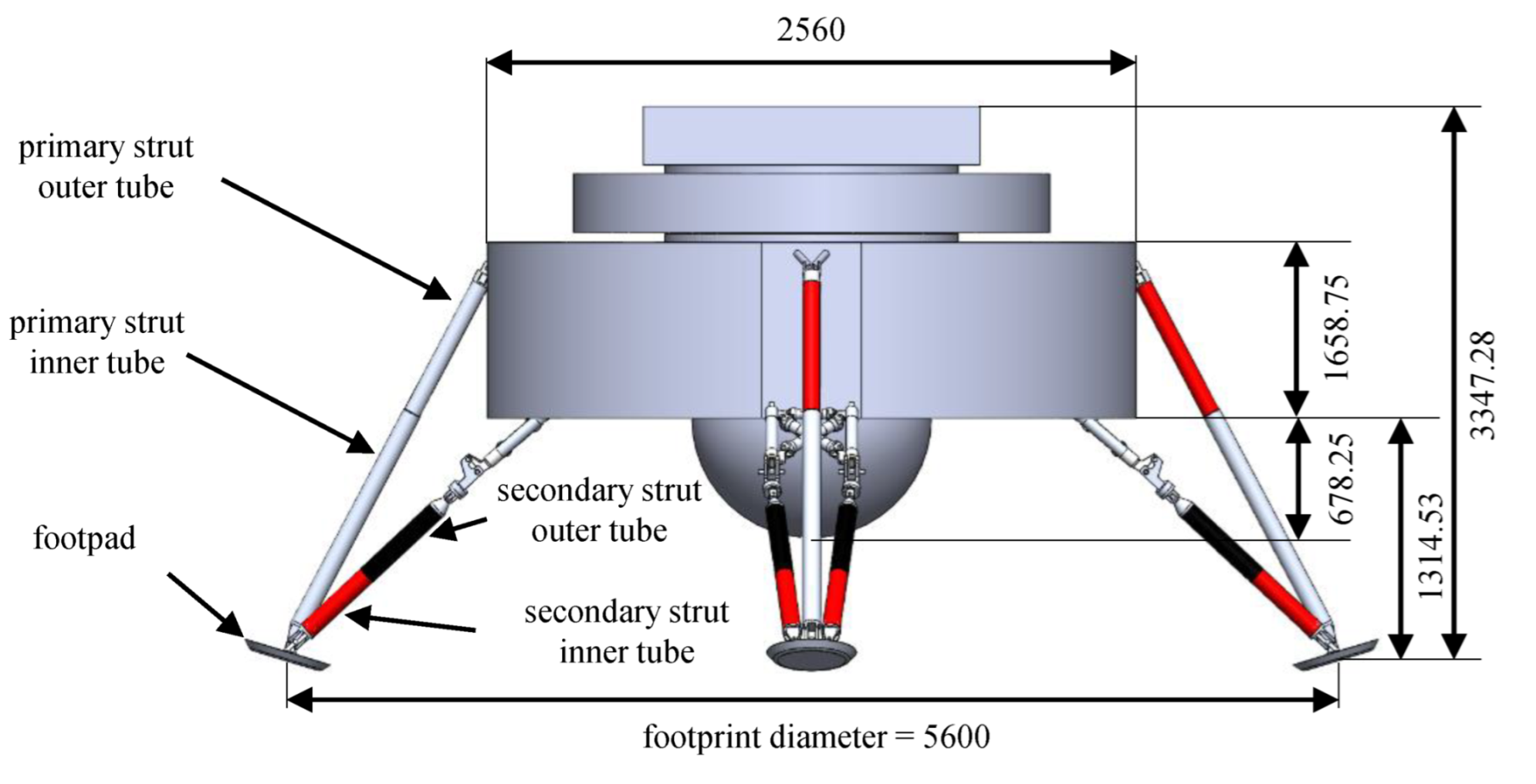
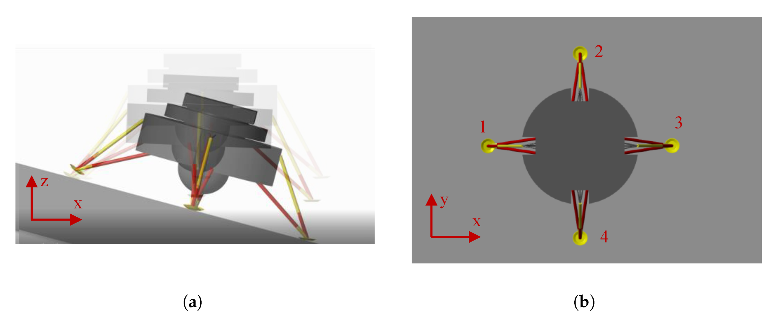
2.1. Landing Gear Layout

The referenced lunar mission for the design of the leveling actuator was the European Space Agency’s (ESA) European Larger Logistic Lander (EL3) framework [16]. In this context, the main objective is to ensure sustainable exploration, both in terms of sustainable human activities on the Moon and the ability to safely and accurately deliver payloads to the lunar surface [17]. Namely, the mission should present the technology to achieve a precise and suitably damped landing while trying to avoid various hazards, including rocks and cavities on the lunar surface. The lander’s main geometrical specifications are highlighted in Figure 1.
In addition to the parameters presented in Figure 1, the mass requirement on the Moon without cargo is 1600 kg, and the cargo mass is approximately 1500 kg. In terms of its dimensions, the lander’s diameter and height can reach up to 4.5 m and 6 m, respectively. The lander legs are folded during launch and deployed through a latching mechanism for landing. Their aim is to ensure stability during landing on moon surface slopes of up to 15 and create sufficient vertical clearance to avoid impacts with rocks up to 0.5 m in height.
Namely, two leg layouts can be exploited: cantilever and inverted tripod (as in Figure 1). The two configurations’ main differences are the anchoring points of the secondary struts. In the cantilever type, these struts are fixed to a certain length for the primary one and mainly experience axial loads, whereas the primary strut is subject to bending. Conversely, the secondary struts’ anchoring points for the inverted tripod layout are in the proximity of the footpad (Figure 1), and all the struts experience axial loads. Overall, the work hereby presented considers an inverted tripod leg layout which integrates the ALS within the primary tubulars.
The active leveling system (ALS) actuator has the goal of extending the primary strut of the landing leg to provide the deployment function and compensate for the permanent deformation of the honeycomb crushable absorber after landing. Electro-mechanical actuation is the technology chosen for the ALS due to high reliability and performance with respect to hydraulic actuation, which often requires complex sealing systems in a low-temperature vacuum lunar environment [18]. The ALS actuator design features opposite objectives:
  • Adequate leveling performances for the required application (in terms of leveling load, operational safety and power consumption);
  • Compact size and contained weight (actuator to be fitted within the primary strut tubulars).
Overall, the actuator requirements are summarized in Table 1. Linear electric machines seem to be a straightforward actuator topology for translational load leveling. However, their limited force density suggests the use of rotary electric motors combined with a suitable linear-to-rotary conversion system [19]. Among many options, the screw mechanism is the most appropriate transmission system since it can be easily integrated within the leg layout. Moreover, the possibility to use an irreversible screw mechanism significantly reduces the electric machine effort during operation. Overall, the ALS features a permanent-magnet synchronous motor (PMSM) coupled with an irreversible screw mechanism fitted inside the tube of the leg primary strut. Due to the irreversibility of the proposed actuator, the system guarantees self-locking and back-driving functions coherently with the landing and leveling requirements.
The layout of the proposed actuator integrated within the primary strut of the landing leg is presented in Figure 2. To achieve a compact layout, the screw (6) is fitted within the electric motor (3,9). By featuring a hollow rotor (9), the electric machine is rigidly connected to the screw without any reduction stage. The rotor is supported by means of two angular contact ball bearings (8,10), whose inner rings are locked by threaded locking rings (7,11) and preloaded by axial springs (5). Two housings (2,4) host the outer rings and clamp the stator of the electric machine. Overall, the irreversibility of the screw allows limiting the motor work to active tasks only. In addition, the unique layout of the actuation unit requires the PMSM to be designed in a custom fashion, further enhancing the compactness of the integrated solution.

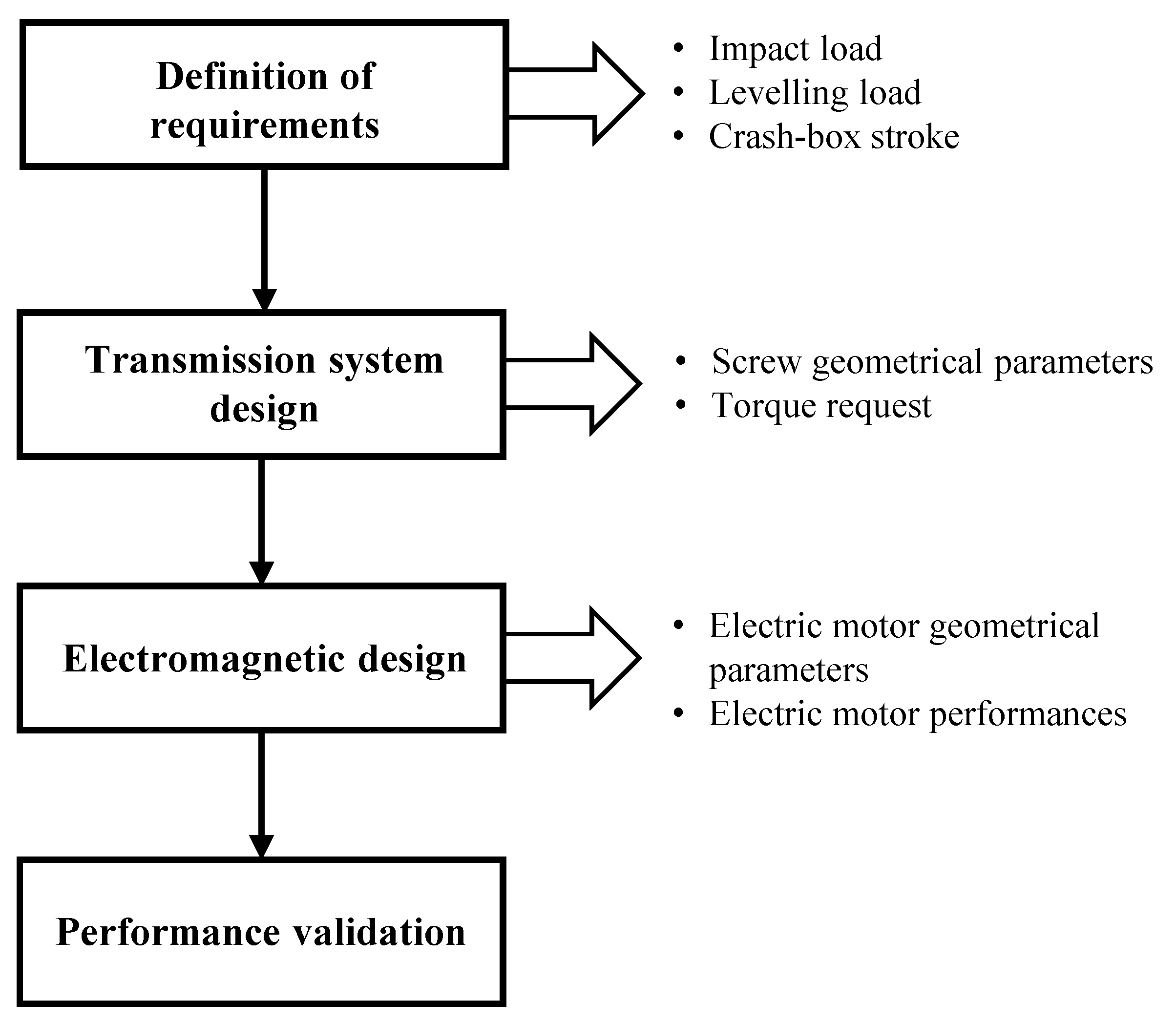
2.2. Actuator Design Methodology

The aim of the proposed methodology is to optimize the performance of the actuator while being compliant with the imposed constraints. Such constraints can be of a geometrical, mechanical or electrical nature and may vary depending on the reference mission and the landing gear layout. The design of the ALS electro-mechanical actuator requires the fulfillment of the following steps, as reported in the flowchart in Figure 3:
1
Definition of requirements: The force required to lift the load is the first parameter to address. The integrated design starts from the simulation results in terms of impact, leveling load and crash box displacement, which are determined through a parametric multi-body landing model in different lunar scenarios. No constraints on the leveling time were provided in the context of the EL3 lander’s development.
2
Transmission system design: The outputs of the multi-body simulations are used as inputs for a parametric optimization algorithm developed to define the mechanical and geometrical parameters of the transmission system.
3
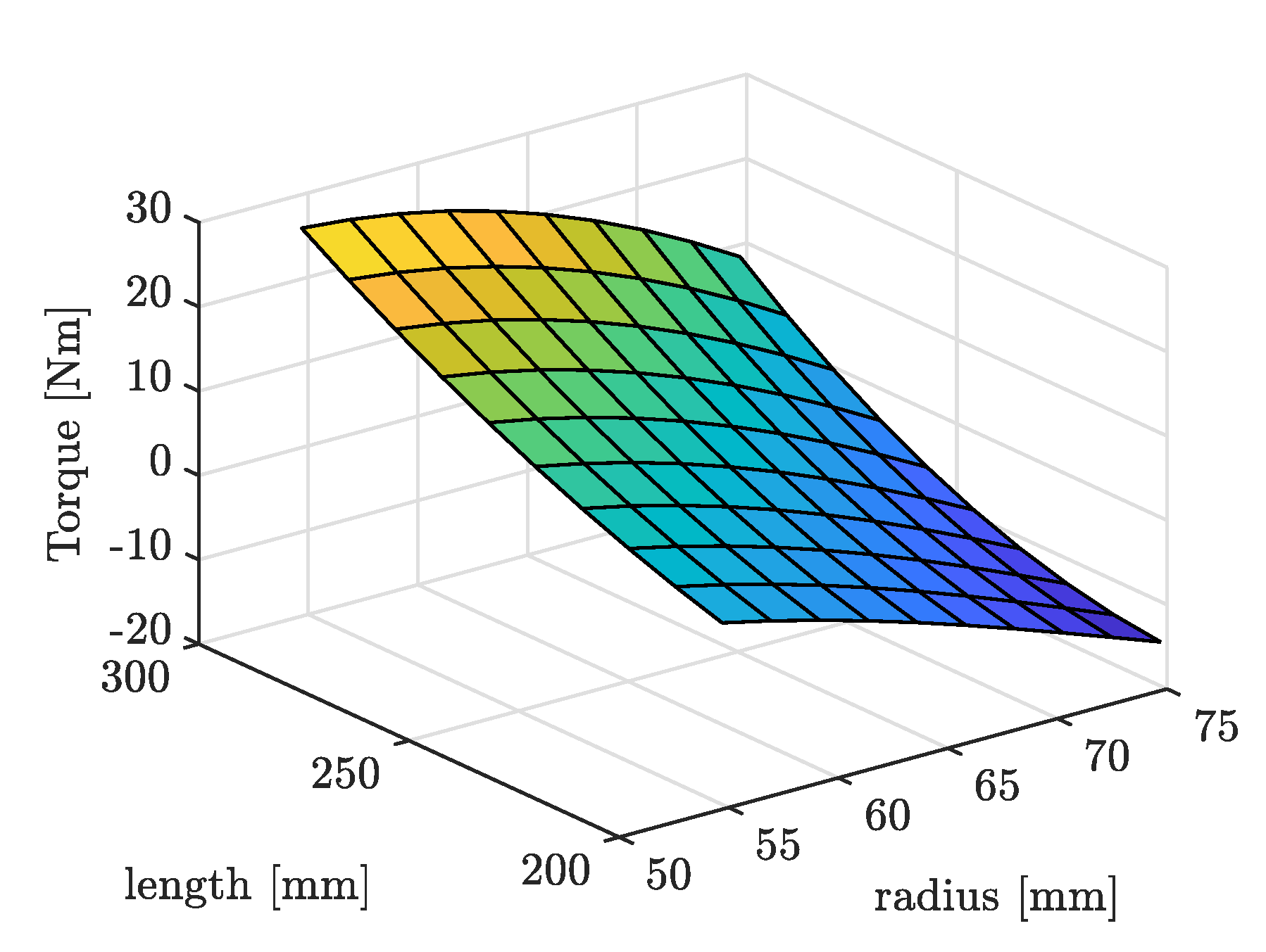
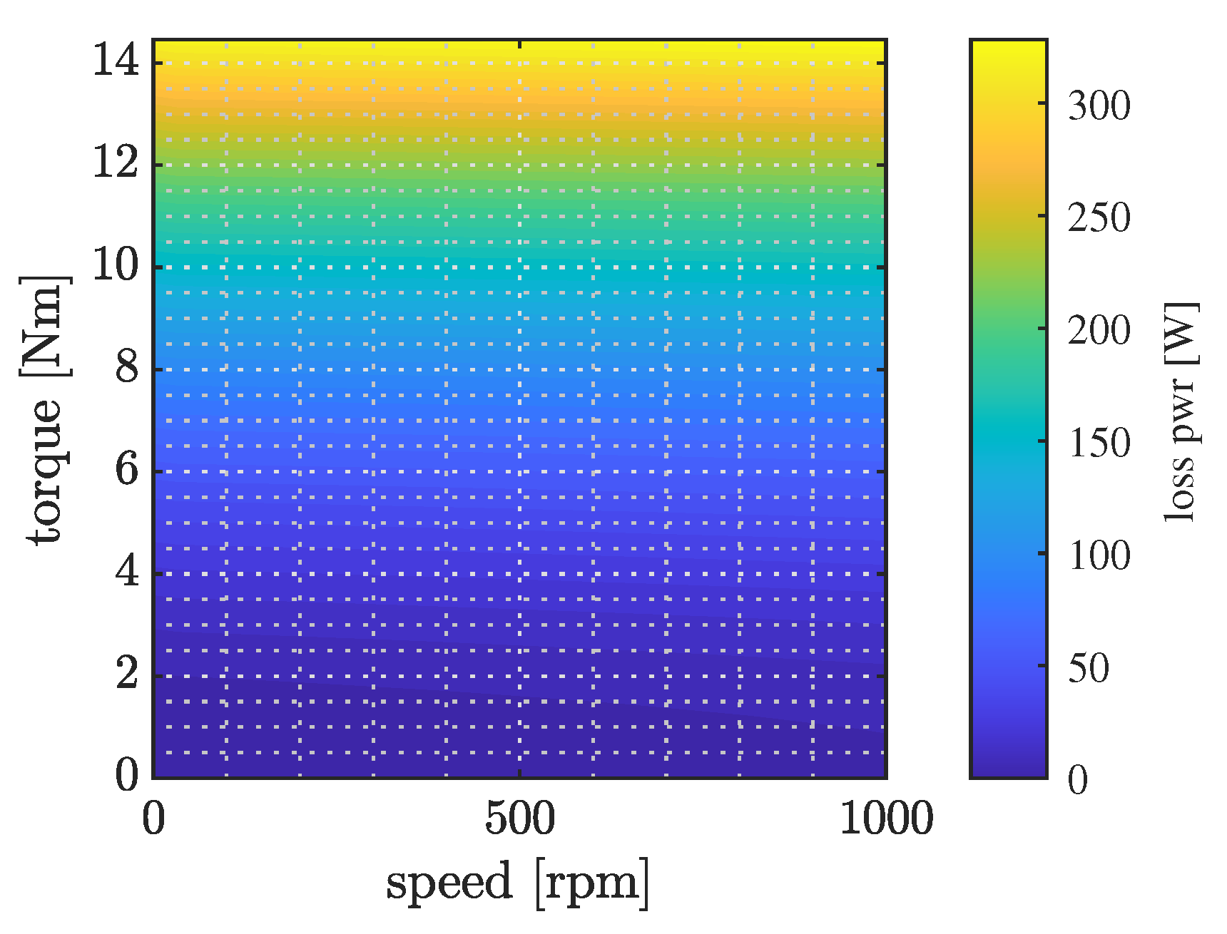
Electromagnetic design: The required torque and the geometrical constraints of the transmission system are inserted into a parametric optimization algorithm for the electric machine design. This step defines the geometrical and electrical characteristics of the PMSM. Electromagnetic finite element analyses are parametrically performed to define the PMSM performance.
4
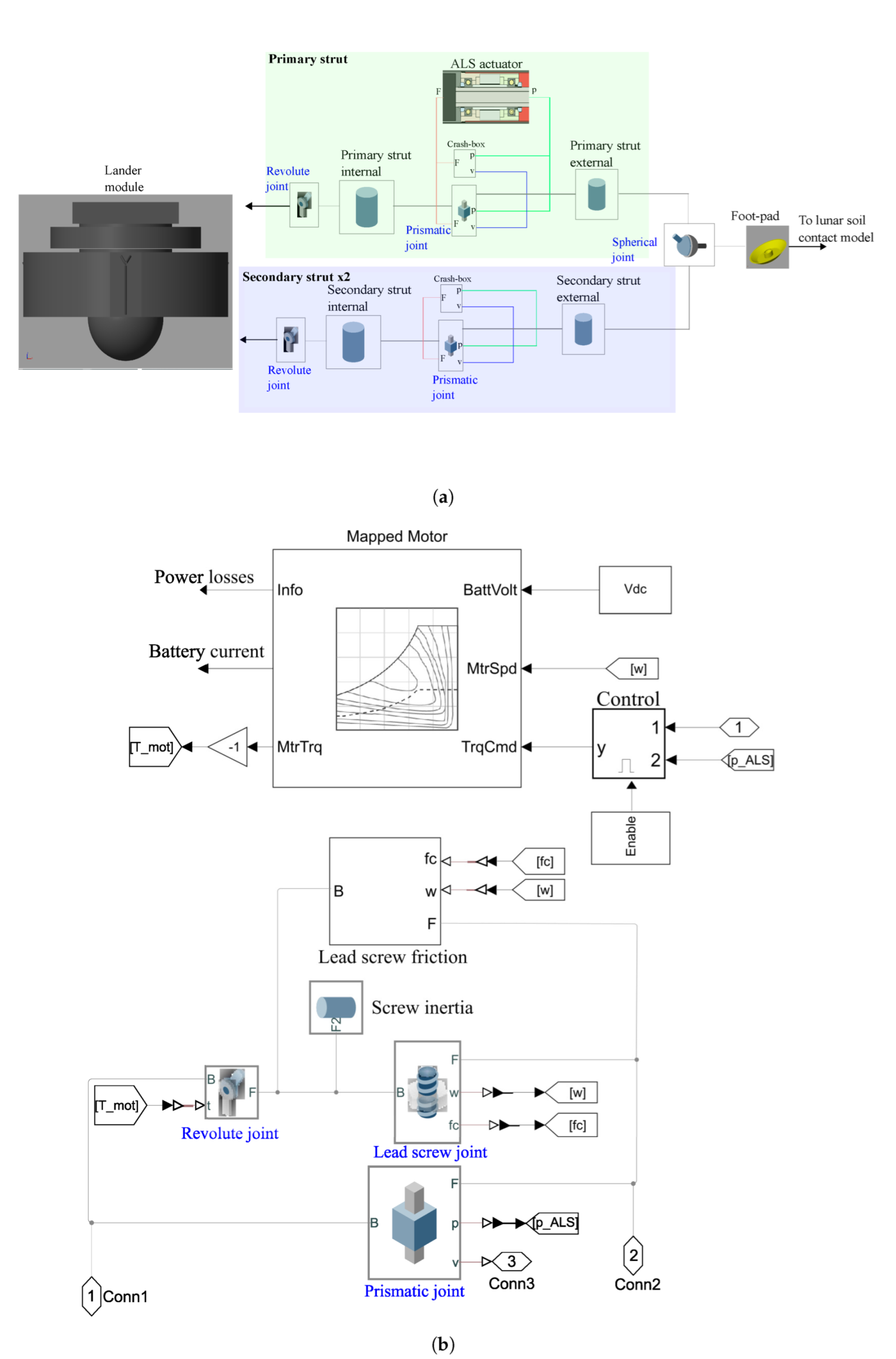
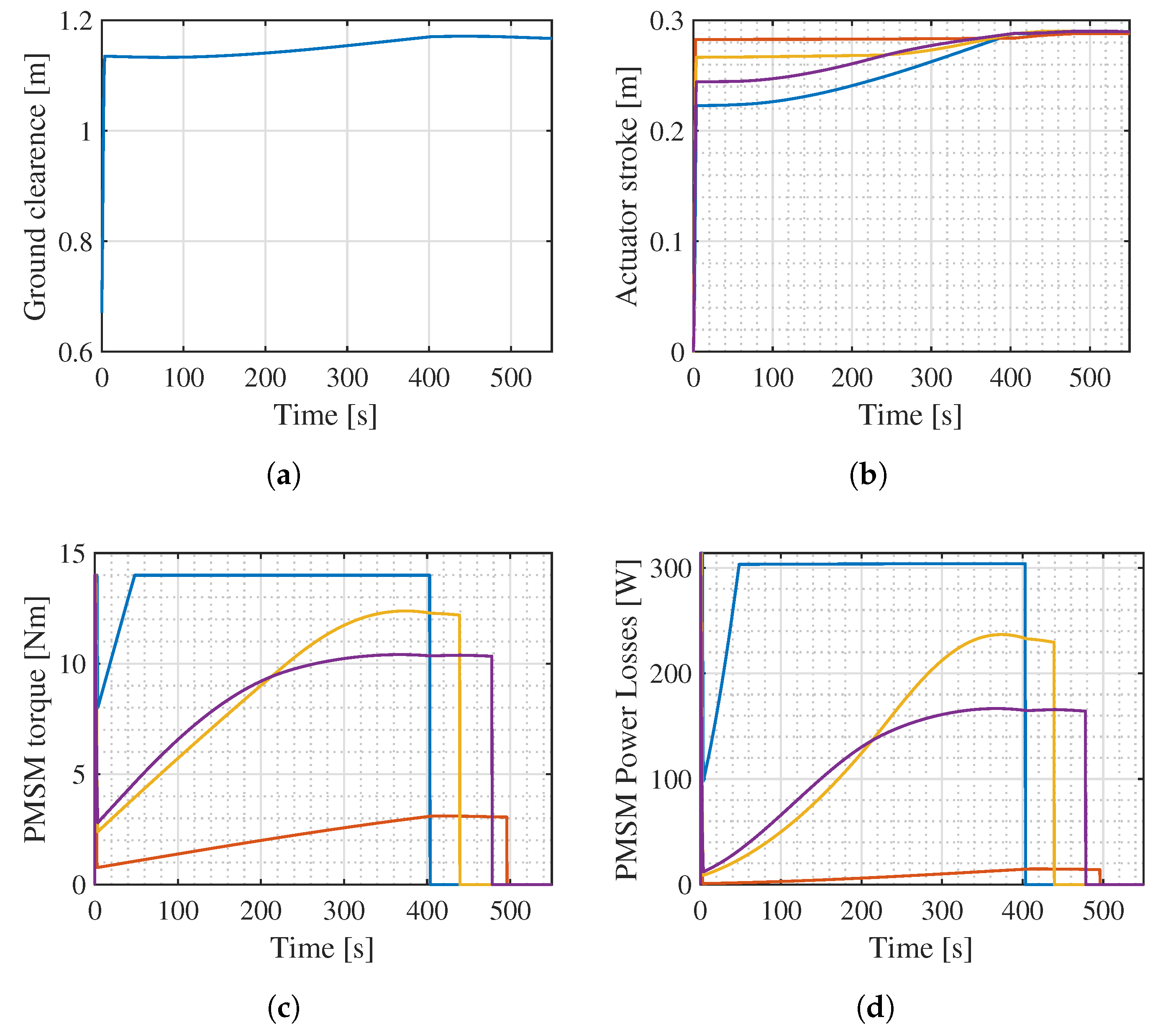
Performance validation: The overall actuator performances are validated through multi-domain virtual test bench simulations. A complete lander multi-body model, including the electro-mechanical leveling actuator, is developed to validate the proposed design over a reference lunar scenario. The leveling time and electric motor power consumption are the main performance metrics.

3. Case Study

In the following section, the developed model for the requirement definitions as far as the mechanical design of the screw transmission system and the electromagnetic design of the electric motor are discussed in detail for the case study of the EL3 lunar lander, as discussed in Section 2.

3.1. Requirement Definitions

The multi-body model of the lander module including four legs was developed in the MATLAB/Simscape® environment. The aim of the multi-body analysis was to define the system requirements in terms of the loads acting on the legs in different landing scenarios, crush box deformations to be compensated and power required to lift the module. The results of the multi-body lunar impact simulations in the identified case scenario served as design inputs for the actuation unit.
Furthermore, the electro-mechanical leveling actuator would be integrated in the multi-body model to validate the performance of the designed system. Figure 4 represents the multi-body model of the landing gear, including the ALS actuator. The latter is explored in Figure 4b.
The lander module was modeled in the CAD environment according to the preliminary size and geometry of the European lander defined in Section 2 and imported into the multi-body environment alongside its inertia properties (e.g., mass, inertia tensor and center of mass position coordinates) defined by the reference mission.
The anchoring points between the module and the legs were modeled as revolute joints. Each strut was modeled as two concentric rigid beams connected by a prismatic joint. The foot-pad was connected to the strut end through a spherical joint. Thus, each leg featured six degrees of freedom: one d.o.f due to the crash absorber strokes in the three struts and three due to the foot pad spherical joint. By including the six d.o.f. of the rigid lander module, the multi-body model used for the landing simulations addressing the design inputs for the ALS, presented a total of 30 d.o.f. with respect to the lunar soil.
The prismatic joint modeling the crash absorber movement is driven by an external force input moving the mobile beam with respect to the base one. To simulate the nonlinear behavior of the crushable absorber, the relative velocity and position between the two beams connected by the prismatic joint are sensed and used as input for an external function modeling both the elastic and dissipative functions, leading to plastic deformation of the honeycomb material. Figure 5 highlights the load-deformation characteristic of the crushable absorber unit, which implements the linear elastic, perfectly plastic characteristic under the imposed deformation. The following load cycle is schematized: the untouched crash unit (0) is deformed up to the yield limit (1). Then, it is further deformed toward point (2), and finally, it is unloaded to (3). As the material undergoes plastic deformation, its yield limit ( x y i e l d ) changes. Specifically, the virgin material features a yield limit x 1 , which updates to x 2 as it is deformed.
The material model is implemented as a piece-wise function. When the imposed deformation is lower than the yield limit ( x < x y i e l d ), the crash box force is
F = [ x ( x y i e l d F c r u s h / k ) ] k + c v
By referring to Figure 5, such behavior occurred in segments 0–1 and 3–2. On the other hand, if the yield limit was exceeded ( x > x y i e l d ), two conditions were present: if the deformation velocity (v) was positive, the material experienced plastic deformation (segment 1–2 in Figure 5) and the yield limit updated to the current deformation ( x y i e l d = x ). If the deformation velocity was negative ( v < 0 ), elastic return occurred (segment 2–3). Mathematically, this can be written as
F = F c r u s h + c v , if v 0 F = F c r u s h k ( x y i e l d x ) + c v , otherwise
The crush strength F c r u s h , the compressive stiffness modulus k and the equivalent damping c are taken from the mechanical properties of commercial crash box units [20]. Finally, the densification phase has been modeled by including an end-stop in correspondence of 70% of the maximum allowable total deflection. A piece-wise function formulation of the crash absorber behavior was selected as a best compromise between the computational cost and simulation accuracy for the considered application [21,22]. The honeycomb crash box model is integrated in both the primary and secondary struts.
To identify the required crash box size and extrapolate the design requirements for the electro-mechanical actuator, the force developed by the crash box F c r u s h and the crash box stroke were recursively varied in the identified scenario, starting from the kinetic energy absorption requirement for the reference scenario described in Table 2. In each landing simulation, the lander module’s vertical deceleration a z was sensed to identify the size of the crash box that minimized the deceleration within the landing stability limits [10].
Lastly, the contact between the foot pad and the lunar soil was modeled by using the penalty method [23], allowing for penetration between the bodies in contact. Both normal and frictional contact behavior were applied between the bodies, with the lunar soil modeled as a plane and the foot pad contact surface modeled as convex hull. The normal contact forces were computed using an equivalent spring-damper system. Then, the contact stiffness, damping and friction coefficient were computed according to [24]. The frictional force lies in the contact plane and opposes the relative tangential velocities between the two bodies near the area of penetration.
In addition to the requirement definition function, the developed model is exploited for the virtual validation step of the design methodology. For the performance assessment purpose, the leveling electro-mechanical actuator model was integrated within the primary struts of the lander legs as reported in Figure 4. The trapezoidal screw transmission system is accounted for by a prismatic joint between the two coaxial tubes of the strut, in parallel with a revolute joint and a lead screw joint. The lead screw friction losses are taken into account by applying a resistive torque computed as follows:
T f r i c t i o n = F l o a d r s c r e w μ
where F l o a d is the normal impact load applied to the screw, r s c r e w is the nominal screw radius and μ is the friction coefficient considered in static and kinematic conditions according to an imposed velocity threshold.
The actuation is provided by an electric motor, which applies torque to the revolute joint coaxial with the lead screw one, as shown in Figure 4. The PMSM was modeled while exploiting an energetic approach. Namely, the power losses in the torque-speed plane and the torque limit determined by the FE simulations are sufficient to adequately model the electric machine behavior. Then, the rotational speed of the lead screw joint is used as a feedback signal for the electric motor model to compute the actuation torque. The torque command is provided to the electric motor through a PI controller, in which the relative position of the two coaxial sliding beams is used to drive the control strategy. The target of the controller is to compensate for the crash box deformation.
The results of the multi-body landing simulations, along with the validation of the actuator performance, are discussed in Section 4.

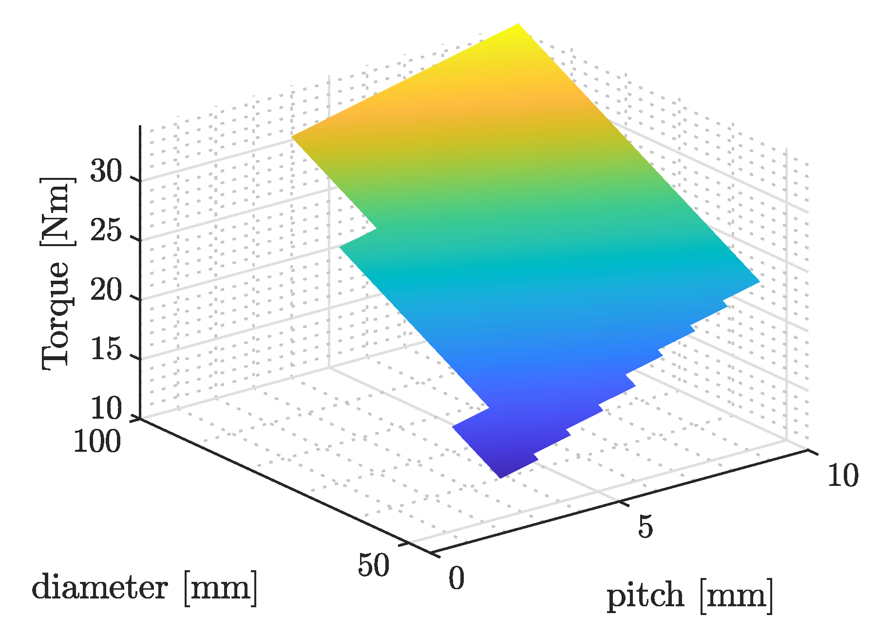
3.2. Transmission System Design

Dealing with the transmission system, an irreversible trapezoidal lead screw was selected as the most suitable solution. The relevant parameters considered for the screw transmission system are listed in Table 1.
The screw design parameters were the nominal diameter d, the nut diameter d n u t , the screw pitch p and the inner diameter d i n . The friction angle of the screw is defined as
Φ = arctan ( f cos ( θ / 2 ) )
while the thread angle α is
α = arctan [ 2 p π ( d + d n u t ) ]
With these two variables, it is possible to define the tangential load as function of the normal load acting on the screw:
F T ( α , ϕ ) = F l e v ( tan ( α ) + tan ( ϕ ) 1 tan ( α ) tan ( ϕ ) )
Furthermore, since the nut diameter can be expressed as d n u t = d p , the actuation torque is derived as a function of the nominal diameter and screw pitch:
T ( α , ϕ ) = F T 4 ( d + d n u t )
The inner diameter d i n is computed while accounting for the buckling verification of the screw at the impact load for the defined safety factor S P l a n d :
d i n = d n u t 4 64 S P L a n d ( 2.1 l ) 2 E π 4
The solutions for the inner diameter d i n with imaginary parts equal to zero satisfy the buckling requirements. Having defined the relevant screw design parameters, a parametric sweep over different pairs of d and p was performed based on the following constraints:
  • Irreversibility of the screw profile: η ( d , p ) < 50 % ;
  • Efficiency: η ( d , p ) η m i n ;
  • Mass: m ( d , p ) m m a x ;
  • Buckling verification: I m [ d i n ( d , p ) ] = 0 .
Here, the minimum efficiency η m i n is set to 0.1 , and the maximum mass constraint m m a x is 10 kg. These constraints are related to both the functional and geometrical requirements of the proposed layout. The obtained results are presented in terms of a 3D map, highlighting the pitch p, nominal diameter d and torque T over the constrained regions. Considering a screw pitch between 2 and 10 mm and a diameter between 40 and 100 mm, the results of the parametric analysis are presented in Figure 6.
As result, the main screw parameters were obtained by considering the minimum constrained torque that satisfied the requirements. Table 3 lists the overall values obtained from the aforementioned analysis.

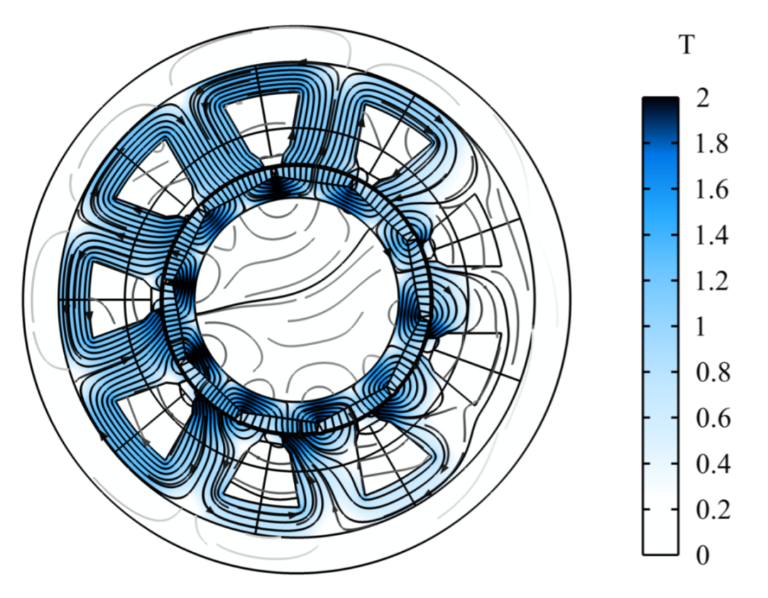
3.3. Electromagnetic Design

After discussing the ALS mechanical design, it is worth investigating the methodologies followed for designing the electromagnetic side of the actuator (i.e., the electric machine). Specifically, the first decision concerns the choice of either a linear or rotary machine. Given the nature of the task that the actuation unit should attain, it would seem straightforward to use a linear electric machine. Although the transmission system could be avoided, linear electric machines are often characterized by low power-to-weight ratios when compared with rotary ones. Hence, they become unsuitable for an application in which size and weight are of paramount importance. Thus, the ALS electric machine typology is a permanent magnet synchronous machine (PMSM), being preferred over other rotary typologies for its reliability, compactness and power density. Since such a machine is rigidly coupled to the irreversible screw, its rotor must be hollow to allow the mating between the screw and lead screw, as shown in Figure 2. The requirements for designing the electric machine can be derived from the mechanical side of the actuation concerning the irreversible screw design. Geometrically, the screw’s nominal diameter d must coincide with the PMSM rotor inner diameter, and the PMSM’s outer diameter is constrained by the leg tube’s inner diameter. The PMSM axial length is only constrained by the screw length, representing an upper bound for the design. In terms of performance, the torque requirement can be extrapolated from the screw’s mechanical design, whereas no constraints are imposed for the maximum angular speed.
The definition of a pseudo-analytical model coupling mechanical, electrical and magnetic domains is the first step in designing such an electric machine. A portion of the PMSM cross-section, along with the main geometrical parameters, is depicted in Figure 7.
As can be noticed, the stator assumed a slotted configuration to distribute evenly the magnetic flux, whereas a surface-mounted magnet configuration was selected for the rotor. Furthermore, l m represents the magnets’ thickness, whereas w b i represents that of the rotor. The first parameters to consider are the number of slots N s and magnet pairs N p of the electric machine. Although an even ratio between the two quantities allows one to minimize the torque ripple content, the higher the number of magnet pairs, the higher the theoretical torque of the electric machine [25]. Moreover, the parameter choices should also follow a process of design for manufacturability. The definition of such parameters allows one to properly define the optimization routine implemented for the preliminary design of the PMSM cross-section.
The pseudo-analytical model was created by starting from the equations in [25] and performing a numerical sweep across the following design variables: the stator’s outside radius R s o , available axial length L a x , number of stator slots N s and magnet pairs N p . The model’s optimization criterion is the maximization of the PMSM’s theoretical maximum torque. The constraints can be divided into geometrical and performance boundaries. In the former, R s o spanned between 50 and 75 mm, whereas L a x spanned between 200 and 300 mm, accounting for the leg tube’s geometrical constraints. On the other hand, values of N s between 4 and 12 and values of N p between 2 and 8 were considered. Moreover, the wire’s RMS current density J w i r e was set to 6 A / mm 2 , the coil packing factor k c p was set to 0.35 , and the lamination stacking factor k s t was set to 0.95. Lastly, a lower bound of 2 mm was set for the magnet’s radial thickness l m due to manufacturability reasons. The results in terms of torque production versus size are presented in Figure 8. It is important to point out that each 3D point in Figure 8 considers the value pair of N s and N p that maximizes the torque output. As can be noticed, the PMSM torque experienced a direct proportionality with respect to its axial length, whereas the stator radius R s o was inversely proportional to the torque production. Hence, the PMSM size was selected so that the torque requirement from the mechanical side of the actuation was matched. As can be noticed, different configurations of the radial and axial dimensions were available. Since the ALS was supposed to be integrated within the lander primary strut, the radial constraint was considered more relevant than the axial one.
All in all, a PMSM outer radius R s o of 55 mm, a 200-mm axial length L a x , 9 stator slots N s and 5 magnet pairs N p represent the outcome of the optimization routine. Table 4 presents the relevant parameters of the permanent-magnet synchronous machine.
From the definition of such parameters, it is possible to have a preliminary design of the electric machine. To validate the design, a parametric electromagnetic finite element analysis was conducted within the COMSOL Multiphysics environment. Specifically, the simulation took as input a parametrized model of the PMSM geometry and output the magnetic flux density norm B distribution across the machine cross-section and the torque production over a limited angle span. Figure 9 and Figure 10 present the FEM results in terms of magnetic flux density and torque production, respectively.
As can be highlighted from Figure 9, the average magnetic flux density norm B was around 1 T, which was below the iron magnetic saturation bound. Moreover, Figure 10 presents the torque production over the rotor angle. The average value was 15.03 Nm, in line with the torque requirement of the ALS and the results of the optimization routine. Once the PMSM design was completed, it was worth finding a way to characterize such an electric machine within the multi-body simulations. Namely, Altair FluxMotor was exploited to perform finite element analysis and characterize the electric machine by means of either efficiency or power loss maps. Simulations were performed while considering suitable torque and angular speed arrays to characterize the operating behavior of the electric machine. Finally, Figure 11 presents the total loss power of the electric machine in the torque-speed plane.
As can be noticed, the maximum power loss was around 350 W, given by the combination of Joule losses and strongly being related to the current (i.e., torque apart from the motor constant k t ) and iron losses, correlated with the angular speed of the electric machine. The results of Figure 11 were then exploited within the multi-body model to create a 2D look-up table of the machine power loss (as shown in Figure 4), adequately representing the PMSM behavior in each operating point of the torque-speed plane.

4. Results

The aim of this section is to validate the design of the actuator discussed for the analyzed case study through a set of landing and leveling multibody simulations. The goal was to assess the stability of the landing legs layout while providing the design input to the ALS actuator as presented in the methodology (Section 2). Hence, the lander legs’ assembly, without the ALS, was simulated in several impact scenarios. Through iterative simulations, the optimum crash box force able to provide a stable landing by guaranteeing the required kinetic energy absorption ( 19.7 kJ for the scenario in Table 2) while minimizing the vertical deceleration was found to be 14 kN for each leg. The simulations were performed in the most severe landing scenario according to [26]. With respect to the cited reference scenario, the horizontal impact speed was negative, forcing the lander toward the slope. The lander impacted the lunar soil on one leg only, representing the most severe landing condition, as shown in Figure 12. The main parameters of the simulated scenario are reported in Table 2.
As reported in Figure 13a, the maximum acceleration achieved by the lander module was below the target limit of 50 m/ s 2 [10]. The simulation results in Figure 13 were used as the design input of the leveling system actuator. In detail, the design inputs for the ALS actuator were the impact force acting on the leg and the maximum deformation of the crash box (Figure 13b,c, respectively). The maximum axial load sensed on the primary strut of the landing gear equipped with the selected crash box was 15 kN, whereas the maximum crash box stroke was 220 mm, achieved by the first leg in contact with the lunar soil.
Figure 14 presents the virtual validation of the ALS actuator’s performance, simulating the complete lander leg assembly, including the ALS actuator model, which was presented in Section 3. The leveling phase was simulated in the reference scenario in Table 2. The maximum stroke to compensate was set to 300 mm, being the maximum allowable plastic displacement of the honeycomb buffer. The model accounted for both the mechanical losses of the screw’s transmission system and the electrical power losses of the PMSM. The relative positions of the two coaxial sliding beams of the primary struts were provided as feedback to the P I controller, piloting the command torque signal of each electric motor. The controller of each actuator was tuned to guarantee an adequate leveling time with limited energetic impact. When the target leveling position of each actuator was reached, the reference torque was forced to zero, enhancing the self-locking function of the irreversible transmission. In light of the leveling simulation results, in a time frame of 500 s, the ALS actuator was able to completely compensate for the crash box plastic’s deformation, leveling the lander (Figure 14b). The maximum torque provided by the PMSM on the most loaded leg was 14 Nm. The maximum torque, together with the maximum power losses, for the simulated scenario were related to the most loaded leg in contact with the lunar soil (Figure 14c,d respectively).
Consequently, the actuator integrated in leg 3 (Figure 12) presented the higher power consumption. The peak power demand was 2000 W, while the mean electrical power was 305 W and the energy consumption was 129 kJ for the simulated leveling event. Thus, the mean total power consumption, considering the four leveling actuators, was 733 W, with a total energy consumption of 277 kJ for the simulated time frame of 550 s.

5. Conclusions

The present paper described a novel system-level design methodology for an active leveling actuator for lunar landing gear application. The presented methodology addressed the integrated sizing of the electric motor and the transmission system within the performance and packaging constraints. The design methodology was applied to the case study of the European Large Logistic Lander (EL3) and validated through landing and leveling simulations at the system level. The obtained actuator features a compact design integrated within the inverted tripod leg layout. The actuator was characterized in terms of the leveling time and power consumption. From a performance perspective, it yielded adequate leveling at 500 s with a mean power consumption of 733 W .
The simulation results addressed the importance of the optimal design methodology of integrated actuators in the context of sustainable lunar exploration missions.

Author Contributions

Conceptualization, R.M., M.P., N.A. and S.S.; methodology, R.M., M.P., S.C., R.G. and N.A.; validation, R.M., M.P. and S.C.; writing—original draft R.M. and M.P.; writing—review and editing, S.C., R.G. and N.A. All authors have read and agreed to the published version of the manuscript.

Funding

This research was funded by Thales Alenia Space.

Data Availability Statement

Data available on request due to restrictions.

Acknowledgments

The authors want to acknowledge the support of Thales Alenia Space in the development of this manuscript.

Conflicts of Interest

The authors declare no conflict of interest.

References

  1. Rogers, F.W. Apollo Experience Report—Lunar Module Landing Gear Subsystem; Technical Report; National Aeronautics and Space Administration (NASA): Washington, DC, USA, 1972. [Google Scholar]
  2. Rew, D.Y.; Ju, G.; Lee, S.; Kim, K.; Kang, S.W.; Lee, S.R. Control system design of the Korean lunar lander demonstrator. Acta Astronaut. 2014, 94, 328–337. [Google Scholar] [CrossRef]
  3. Ponnusamy, D.; Maahs, G. Development and testing of leg assemblies for robotic lunar lander. In Proceedings of the 14th European Space Mechanisms and Tribology Symposium, Constance, Germany, 28–30 September 2011; pp. 485–492. [Google Scholar]
  4. Maeda, T.; Ozaki, T.; Hara, S.; Matsui, S. Touchdown Dynamics of Planetary Lander with Translation–Rotation Motion Conversion Mechanism. J. Spacecr. Rocket. 2017, 54, 973–980. [Google Scholar] [CrossRef]
  5. Lognonné, P.; Banerdt, W.B.; Giardini, D.; Pike, W.T.; Christensen, U.; Laudet, P.; De Raucourt, S.; Zweifel, P.; Calcutt, S.; Bierwirth, M.; et al. SEIS: Insight’s seismic experiment for internal structure of Mars. Space Sci. Rev. 2019, 215, 1–170. [Google Scholar] [CrossRef] [PubMed]
  6. Wang, C.; Nie, H.; Chen, J.; Lee, H.P. The design and dynamic analysis of a lunar lander with semi-active control. Acta Astronaut. 2019, 157, 145–156. [Google Scholar] [CrossRef]
  7. Yin, K.; Gao, F.; Sun, Q.; Liu, J.; Xiao, T.; Yang, J.; Jiang, S.; Chen, X.; Sun, J.; Liu, R.; et al. Design and soft-landing control of a six-legged mobile repetitive lander for lunar exploration. In Proceedings of the 2021 IEEE International Conference on Robotics and Automation (ICRA), Xi’an, China, 30 May–5 June 2021; pp. 670–676. [Google Scholar]
  8. Rippere, T.B.; Wiens, G.J. An approach to designing passive self-leveling landing gear with application to the Lunar Lander. In Proceedings of the 40th Aerospace Mechanisms Symposium, Cocoa Beach, FL, USA, 12–14 May 2010. [Google Scholar]
  9. Gollins, N.; Timman, S.; Braun, M.; Landgraf, M. Building a European lunar capability with the European large logistic lander. In Proceedings of the EGU General Assembly Conference Abstracts, Online, 4–8 May 2020; p. 22568. [Google Scholar]
  10. Bo, L.; Zhang, M.; Hanyu, L.; Hong, N. Optimization design containing dimension and buffer parameters of landing legs for reusable landing vehicle. Chin. J. Aeronaut. 2022, 35, 234–249. [Google Scholar]
  11. Sciascera, C.; Giangrande, P.; Brunson, C.; Galea, M.; Gerada, C. Optimal design of an electro-mechanical actuator for aerospace application. In Proceedings of the IECON 2015—41st Annual Conference of the IEEE Industrial Electronics Society, Yokohama, Japan, 9–12 November 2015; pp. 001903–001908. [Google Scholar] [CrossRef]
  12. Li, W.; Fielding, J. Preliminary study of EMA landing gear actuation. In Proceedings of the 28th International Congress of the Aeronautical Sciences, Brisbane, Australia, 23–28 September 2012; pp. 23–28. [Google Scholar]
  13. Budinger, M.; Liscouët, J.; Hospital, F.; Marè, J.C. Estimation models for the preliminary design of electromechanical actuators. Proc. Inst. Mech. Eng. Part G J. Aerosp. Eng. 2012, 226, 243–259. [Google Scholar] [CrossRef]
  14. Budinger, M.; J-C, P.; Gogu, C.; Fraj, A. Scaling-law-based metamodels for the sizing of mechatronic systems. Mechatronics 2014, 24, 775–787. [Google Scholar] [CrossRef]
  15. Budinger, M.; Reysset, A.; El Halabi, T.; Vasiliu, C.; Marè, J.C. Optimal preliminary design of electromechanical actuators. Proc. Inst. Mech. Eng. Part G J. Aerosp. Eng. 2014, 228, 1598–1616. [Google Scholar] [CrossRef]
  16. ESA. European Large Logistics Lander. Available online: https://www.esa.int/Science_Exploration/Human_and_Robotic_Exploration/Exploration/European_Large_Logistics_Lander (accessed on 28 April 2022).
  17. Carpenter, J.; Fisackerly, R.; Espinasse, S. The Lunar Exploration Definition Team. Lunar Exploration Objectives and Requirements Definition; Technical Report; European Space Agency: Paris, France, 2010. [Google Scholar]
  18. Arm, P.; Zenkl, R.; Barton, P.; Beglinger, L.; Dietsche, A.; Ferrazzini, L.; Hampp, E.; Hinder, J.; Huber, C.; Schaufelberger, D.; et al. Spacebok: A dynamic legged robot for space exploration. In Proceedings of the 2019 International Conference on Robotics and Automation (ICRA), Montreal, QC, Canada, 20–24 May 2019; pp. 6288–6294. [Google Scholar]
  19. Amati, N.; Festini, A.; Tonoli, A. Design of electromagnetic shock absorbers for automotive suspensions. Veh. Syst. Dyn. 2011, 49, 1913–1928. [Google Scholar] [CrossRef]
  20. Hexcell Corp. Hexweb Honeycomb Catalogue. Available online: https://www.hexcel.com/Products/Honeycomb/HexWeb-Honeycomb (accessed on 28 April 2022).
  21. Liu, Y.; Song, S.; Li, M.; Wang, C. Landing stability analysis for lunar landers using computer simulation experiments. Int. J. Adv. Robot. Syst. 2017, 14, 1729881417748441. [Google Scholar] [CrossRef]
  22. Pham, V.L.; Zhao, J.; Goo, N.S.; Lim, J.H.; Hwang, D.S.; Park, J.S. Landing stability simulation of a 1/6 lunar module with aluminum honeycomb dampers. Int. J. Aeronaut. Space Sci. 2013, 14, 356–368. [Google Scholar] [CrossRef]
  23. Zheng, G.; Nie, H.; Chen, J.; Chen, C.; Lee, H.P. Dynamic analysis of lunar lander during soft landing using explicit finite element method. Acta Astronaut. 2018, 148, 69–81. [Google Scholar] [CrossRef]
  24. Wang, S.C.; Deng, Z.Q.; Hu, M.; Gao, H.B. Dynamic model building and simulation for mechanical main body of lunar lander. J. Cent. South Univ. Technol. 2005, 12, 329–334. [Google Scholar] [CrossRef]
  25. Hanselmann, D.C. Brushless Permanent Magnet Motor Design. Fac. Staff Monogr. Publ. 2003, 231. [Google Scholar]
  26. Rapisarda, A.; Amati, N.; Gagliardi, L.; Detoni, J.G.; Galluzzi, R.; Gasparin, E.; Nebiolo, M.; Stitio, A. Design and Experimental Characterization of Electromagnetic Shock Absorbers for Landing Gears. In Proceedings of the International Astronautical Congress: IAC Proceedings, Naples, Italy, 1–5 October 2012. [Google Scholar]
Figure 1. Lunar lander configuration, main parameters and deployed configuration. All dimensions in mm.
Actuators 11 00263 g001
Figure 2. Landing gear primary strut CAD model (a) and ALS actuator CAD model (b): nylon bushing (1), housing (2,4), EM stator (3), preload spring (5), screw (6), threaded locking ring (7,11), angular contact ball bearing (8,10), and EM rotor (9).
Actuators 11 00263 g002
Figure 3. Design methodology flowchart.
Actuators 11 00263 g003
Figure 4. Multi-body model of the landing gear (a). ALS subsystem (b).
Actuators 11 00263 g004
Figure 5. Honeycomb crash absorber load-deformation characteristic.
Actuators 11 00263 g005
Figure 6. Constrained screw torque T results as function of pitch p and diameter d.
Actuators 11 00263 g006
Figure 7. PMSM cross-section and main geometrical parameters.
Actuators 11 00263 g007
Figure 8. PMSM torque with respect to stator outside radius and axial length.
Actuators 11 00263 g008
Figure 9. PMSM magnetic flux density distribution (Tesla).
Actuators 11 00263 g009
Figure 10. PMSM torque production versus rotor angle span.
Actuators 11 00263 g010
Figure 11. PMSM total power loss in torque-speed plane.
Actuators 11 00263 g011
Figure 12. Landing impact animation, multi-body simulation. (a) Front view. (b) Top view.
Actuators 11 00263 g012
Figure 13. Landing multi-body simulation results for leg 1 (orange), leg 2 (yellow), leg 3 (blue) and leg 4 (violet) according to Figure 12b. (a) Vertical acceleration. (b) Axial load on primary strut. (c) Honeycomb crash box impact stroke.
Actuators 11 00263 g013
Figure 14. Leveling phase multi-body simulation for leg 1 (orange), leg 2 (yellow), leg 3 (blue) and leg 4 (violet), according to Figure 12b. (a) Vertical clearance between ground and lander module. (b) Actuator stroke. (c) PMSM torque. (d) PMSM power losses.
Actuators 11 00263 g014
Table 1. Screw input design parameters.
SymbolDescriptionValue
ρ Material density (steel) 7800 kg / m 3
EMaterial Young’s modulus206 GPa
fDynamic friction coefficient 0.1
θ Thread angle30 deg
F l e v Leveling load5300 N
P l a n d Landing impact load15,000 N
SSafety factor2
lLength1320 mm
Table 2. Landing scenario.
SymbolDescriptionValue
V z Vertical landing speed 2.5 m/s
V x Horizontal landing speed 2.5 m/s
α Lunar terrain slope15 deg
μ s Static friction coefficient 0.5
μ d Dynamic friction coefficient 0.7
kContact stiffness 1.65 × 10 5 N/m
cContact damping 2.1 × 10 5 Ns/m
Table 3. Screw design results.
SymbolDescriptionValue
dNominal diameter47 mm
pPitch2 mm
d i n Inner diameter 26.9 mm
d n u t Nut diameter45 mm
TTorque 14.32 Nm
η Efficiency 0.12
mMass estimate6 kg
Table 4. PMSM main parameters.
SymbolDescriptionValue
R r i Rotor inside radius 23.5 mm
R r o Rotor outside radius 30.8 mm
R s i Stator inside radius 31.3 mm
R s o Stator inside radius55 mm
gAir gap length 0.5 mm
w b Back iron width7 mm
w s Slot opening4 mm
L a x PMSM axial length200 mm
Publisher’s Note: MDPI stays neutral with regard to jurisdictional claims in published maps and institutional affiliations.

