Abstract
Foam-based soft actuators are lightweight and highly compressible, which make them an attractive option for soft robotics. A negative pressure drive would complement the advantages of foam actuators and improve the durability of the soft robotic system. In this study, a foam actuator was designed with a negative pressure pneumatic drive comprising bellows air chambers, a polyurethane foam body, and sealing layers at the head and tail. Experiments were performed to test the bending and contraction performances of the actuator with the foaming multiplier and air chamber length as variables. At air pressures of 0–90 kPa, the bending angle and contraction of the actuator increased with the foaming multiplier and number of air chamber sections. The designed actuator achieved a bending angle of 56.2° and contraction distance of 34 mm (47.9% of the total length) at 90 kPa, and the bending and contraction output forces were 3.5 and 7.2 N, respectively. A control system was built, and four soft robots were constructed with different numbers of actuators. In experiments, the robots successfully completed operations such as lifting, gripping, walking, and gesturing. The designed actuator is potentially applicable to debris capture, field rescue, and teaching in classrooms.
1. Introduction
Soft robots have become a hot topic of research in the robotics field owing to their unconstrained degrees of freedom, excellent deformation effect, relatively simple control, higher safety, and low cost. In contrast to the traditional rigid robotics, soft robots can quickly adapt to unstructured environments in high-tech fields such as medical rehabilitation [1,2,3,4], rescue detection [5,6,7], and bionics [8,9,10] and are more convenient for human–robot interactions in everyday environments such as classroom education [11,12] and recreation [13]. Soft robots are potentially applicable to a wide range of industries.
The actuator is the core part of a soft robot, and its performance is mainly determined by the materials and driving method. The materials determine the structural shape and deformation mode of the actuator, while the driving method is closely related to the materials, working environment, and efficiency. One of the most common and widely used driving methods is the pneumatic soft actuator. In recent years, pneumatic actuators with various shapes [14], materials [15], manufacturing methods [16] and driving methods [17] have been developed such as soft grippers [18,19], wearable devices [20,21], and artificial muscles [22,23], which has greatly advanced the field of soft robotics. These actuators are based on flexible materials, which are stretched and bent by the expansion of the elastic cavity for various operations. However, the high density of these materials means that the actuator is greatly affected by its own weight at low air pressure, which hinders its deformation. At high air pressures, the use of silicone and other softer materials will cause a balloon expansion effect. This needs to be limited by the addition of fiber enforcement.
The high porosity and low density of foam materials offer unique advantages for their application to actuators. Compared with other flexible actuators, foam actuators are significantly lower in mass and easier to control. In addition, porous foams are highly compressible with large deformability. Foam actuators can achieve a unique contraction deformation that gives soft robots excellent flexibility beyond bending actuators in tight spaces. In addition, foam materials have a high strain-to-stress ratio that allows the actuator to achieve a large deformation with a small amount of power [24], which reduces the requirements and power consumption of the driving system.
Currently, only limited research has been conducted on applying foam actuators to soft robotics. Kastor et al. [24] and Donatelli et al. [25] both developed tendon-driven polyurethane (PU) foam soft robots. The former has rigid parts such as motors sewn into the robot body to perform compression and folding actions and can generate large deformations of about 70% at low torques of less than 0.2 N/m. Meanwhile, the latter is a soft PU foam robot with 85% softness that can mimic the gait of a caterpillar at a speed of 0.052 body lengths per second to cross obstacle and climb hills. King et al. [26] used the open-mold method to fabricate a tendon-actuated foam hand and performed tests investigating its repeatability, gripping force, and durability, which demonstrated that the hand could reach a maximum gripping force of 5.8 N. Somm et al. [27] proposed a soft robot prototyping technique that integrates sensing and actuation based on expanded PU foam. Their technology simplifies the manufacturing process by integrating user-defined transmission routing points through cable drives to manufacture customized soft robots. However, foam robots driven by tendons are too complicated because of the need for cooperating motors, and integration of the motors with the robot body makes the whole system huge and heavy. Thus, some scholars have designed foam-based soft robotics by using pneumatic driving methods. Figure 1 shows some examples from the literature. Mac Murray et al. [28] used a method similar to the lost-salt process to prepare a silicone skin-coated silicone foam fluid elastic actuator. They fabricated a soft fluid pump with a complex internal and external structure that was capable of pumping liquid at a flow rate of about 430 mL/min at a differential pressure of 14 kPa. Futran et al. [29] proposed a silicone rubber foam actuator driven by traveling waves, which they validated by fabricating a millipede-mimicking robot, with a forward speed of about 1.1 mm/s. Argiolas et al. [11] used a silicone rubber porous elastic foam to sculpt bending actuators, grippers, and other 3D-shaped products that could apply a force of 5 N at the end-effector and pick up objects with a mass of 200 g. In other respects, Peters et al. [30] proposed a hybrid fluid-driven Polyvinyl Alcohol (PVA) foam soft actuator and investigated the actuator displacement and output force characteristics under different air pressure and hydraulic ratios. The results show that a higher percentage of hydraulic action increases the output force and deformation rate of the actuator. Van Meerbeek et al. [31] designed a bicontinuous foam composite comprising a low-melting-point alloy and elastomer that can achieve variable stiffness and self-healing because the composite properties are dominated by the metal and the elastomer at high and low temperatures, respectively. Thus, the previous research on foam actuators has greatly promoted the development of flexible materials, actuation methods, and preparation techniques of soft robots. However, the previous applications of pneumatic drives all used positive-pressure actuators.
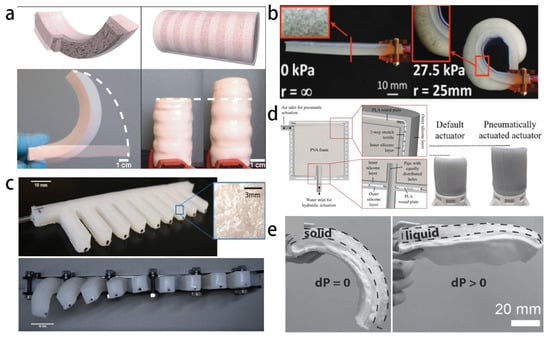
Figure 1.
Soft foam actuators: (a) silicone foam bending actuator manufactured by the lost-salt process [28]; (b) silicone foam bending actuator [29]; (c) traveling wave-driven soft robot made of silicone foam that was inspired by a millipede [11]; (d) hybrid driven PVA foam actuator [30]; (e) composite foam actuator comprising a low-melting-point alloy and elastomer [31].
Foam actuators can also be driven by negative pressure. In contrast with foam actuators driven by positive pressure, actuators driven by negative pressure (i.e., vacuum) can take better advantage of the foam material to give the soft robot better durability and impact resistance while avoiding the risk of overpressure. Robertson et al. [32] designed a low-cost negative pressure-driven soft actuator that is quickly fabricated and that can perform various operations, such as suction manipulation and vertical window climbing. However, their actuator uses the pores of the foam itself as air chambers, which limits the deformation and the angular travel to only 27.3° for a single module. Thus, the above actions require more than three actuators and other rigid components in series to complete which leads to a complex system that is difficult to control. The vacuum and flexural strength limit the amount of deformation of the soft material, so special care needs to be taken regarding the structural design to increase the deformation and degrees of freedom. Joe et al. [33] developed a hybrid pneumatic artificial muscle based on the bellows structure and negative pressure that could achieve a contraction rate of up to 50% and had a payload of 3 kg. However, their focus was on increasing the contraction rate, and their pneumatic artificial muscle could only achieve a single contraction deformation. In complex operating spaces, actuators often need multiple degrees of freedom for increased flexibility.
This research focuses on exploring an actuator design enabling two deformation modes that is capable of applications in a variety of environments, such as debris grasping, field rescue, and classroom teaching. A lightweight and multi-chamber foam actuator with a negative pressure drive was designed comprising four bellows air chambers, open-cell PU foam as the deformable body, and a flexible material as the seal to realize dual-mode deformation of bending and large contraction. The design amplified the deformation effect by minimizing the mass and maximizing the contraction rate. The compressive mechanical behavior of PU foam was characterized, and the main influencing factors were identified. Then, foam actuators with different material and structural parameters were prepared, and their motion characteristics and output forces were characterized. Finally, a drive control system was built, and soft robots with different numbers of actuators were fabricated and applied to lifting heavy objects, grasping objects, walking, and making gestures. This research shows the potential of designed actuator and opens up more possibilities for the development of foam soft robots.
2. Materials and Methods
2.1. Compressive Properties of Foam Materials
The actuator comprising PU foam (HBS905, Hagibis, Beijing) and thermoset PU (HBS870, Hagibis, Beijing) was fully flexible. PU foam has an adjustable density of 55–70 kg/m and has a high resilience and low cost compared with other foam materials. The density of the PU foam and the strain rate of the loading test are important influencing factors of the mechanical properties [34,35]. The density of the selected material was related to the ratio between the two foaming liquids A and B in the foaming process. For a foam with a fixed volume, reducing the foaming liquid increases the foaming multiplier and lowers the density, and vice versa. Therefore, the density was defined in this study in terms of the foaming multiplier. Three foam samples with foaming multipliers of 5/1.15, 5/1.30, and 5/1.50 were prepared for uniaxial compression tests. These tests were performed by using a small universal testing machine (model: INSTRON500N) at three different compressive strain rates of 0.001, 0.01, and 0.1 s−1 (corresponding to displacement rates of 0.05, 0.5, and 5 mm/s, respectively) to simulate the deformation of the material at different inflation rates. These samples were compressed to 80% of their original height, and repeated three times at each strain rate for different foaming multiples and averaged. The compression tests were performed according to the ASTM-3574 standard.
Figure 2 shows the stress–strain curves of the foam samples at different compressive strain rates. The curves all went through three stages: the initial linear elastic region (magnified in the inset), a plateau, and dense region at the end of compression. These curves are expected for the compression of soft porous materials. Table 1 presents the modulus of elasticity E and maximum stress σ measured at 80% strain of the samples at each foaming multiplier. The strain range in the plateau region was proportional to the foaming multiplier, which may be due to the larger cell size of foams with low density, the corresponding deformation space was also larger, so the strain range was wider than for denser foams [36]. The modulus of elasticity and maximum stress increased with the compressive strain rate at the same foaming multiplier except for the 5:1 sample, which showed a decrease in the modulus of elasticity at a strain rate of 0.01 s−1. The decrease in the modulus of elasticity may be because the sample was soft with this foaming multiplier, and the change in strain rate did not have a noticeable effect at the initial stage of compression. However, the stress–strain curves of foam samples with the same foaming multiplier at different strain rates were closer than those for the same strain rate at different foaming multiplier. Therefore, the foaming multiplier (i.e., density) was the main influencing factor for the mechanical properties of PU foam under a compressive load.
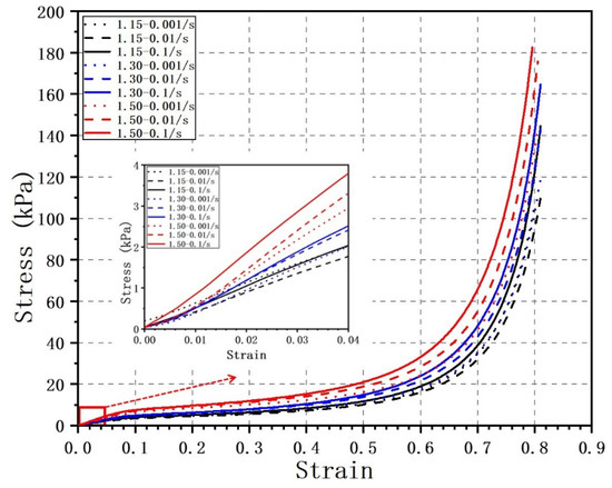
Figure 2.
Stress–strain curves of foam materials under uniaxial compression. The inset shows the liner elastic region.

Table 1.
Statistical data of different foams at three strain rates.
2.2. Structural Design of the Actuators
The design of the actuator was based on two main requirements. First, the actuator should have multiple degrees of freedom and can realize two deformation modes of omnidirectional bending and contraction. Second, the deformation effect should be obvious during bending and contraction, and the actuator has good elasticity when resetting. Figure 3 shows the designed negative pressure-driven foam actuator, which comprised a cylindrical foam body, four bellows-type air chambers, and end caps and sealing layers for the air chambers. The four air chambers were made of commercially available thermoplastic polyurethane thin-walled straw and were symmetrically distributed around the actuator in a square. Four air chambers were used to increase the degrees of freedom. When the air pressures in the four chambers were equal, the actuator contracted; when they were not equal, the actuator bent. End caps were glued to the ends of each chamber to connect the chambers to the extraction line. Sealing layers were placed at each end of the actuator to secure and seal the air chambers, and the foam body was wrapped around the air chambers. The center of the actuator was a hollow structure designed to allow airway to pass through without obstructing deformation when multiple actuators were combined.
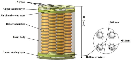
Figure 3.
3D model of the foam actuator.
2.3. Fabrication of the Actuators
Figure 4 describes the fabrication of the foam actuator. The actuator is made by the mold casting method. All molds and the end caps were made by 3D printing.
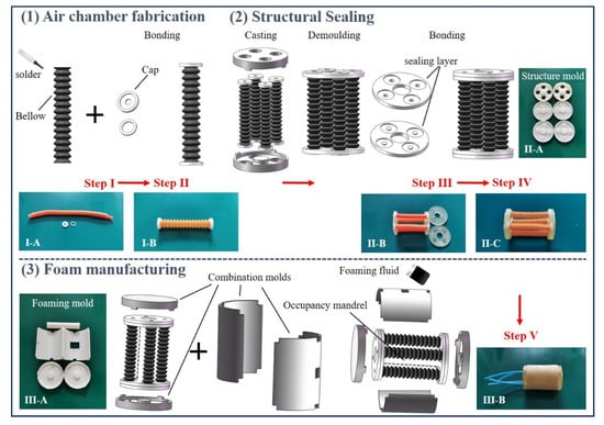
Figure 4.
Actuator fabrication process.
- Bellows air chambers: The thin-walled PU bellows was selected from commercially available drink straw and cut into the required number of sections. Two small rings are used to pass through the first and last ends of the bellows, and a solder glue (WJ-106S, WEIJISEN, Huizhou, China) is applied to the inside of the end cap and fits into the small ring to achieve bonding with the bellows. The small rings and end caps were made of polylactic acid and fabricated by Fused Deposition Modelling (I-A, CoLiDo 1.0, PRINT-RITE, Zhuhai, China);
- Sealing layer: The A and B components of the thermosetting PU were mixed uniformly at a ratio of 1:1. The inner two sealing layers were obtained by combining the four air chambers with the upper and lower two molds (II-A, made of photosensitive resin and fabricated by Digital Light Processing: Form3, formlabs, Engitype, Gig Harbor, WA, USA) and then casting and demolding. The preparation of the sealing layers is completed one at a time. After the first sealing layer is casted and demolded, the whole is turned over and another sealing layer is prepared in the same way. The outer two sealing layers were casted and demolded separately. Trim the edges of each sealing layer after demolding to ensure sealing. The outer two sealing layers were bonded individually to the inner sealing layer by applying thermosetting PU to the sealing layer surface to complete the actuator skeleton;
- Foam: A hollow cylindrical foam body was wrapped around the air chambers, and the tops of the four air chambers were connected to the airway. Specifically, the actuator skeleton obtained in the second part was combined with the top, bottom, left, right, and occupancy mandrel five molds (III-A, made of polylactic acid and fabricated by Fused Deposition Modelling: CoLiDo 1.0, PRINT-RITE, Zhuhai, China) to form a cylinder. The foaming liquid was poured into the square hole reserved in the upper mold. The foaming was allowed to complete before the mold was cooled. The whole process lasted about 20 min.
The above preparation process was used to fabricate actuators with different foaming multipliers for a given number of air chamber sections and different air chamber sections for a given foaming multiplier, as given in Table 2. These were used in the subsequent tests.
Table 2.
Actuators with different materials and construction parameters.
3. Experimental
3.1. Motion and out Force Characterization
The actuator performance was judged in terms of the motion characteristics and output force. Once the actuators were prepared, the motion characteristics were first analyzed to determine the optimal parameters. Then the output force of the actuators was tested.
The test setup for bending and contraction is shown in Figure 5a. The actuator was fixed vertically on the stand, and a negative pressure of 20–90 kPa was applied. A digital camera (D700, Nikon, Tokyo, Japan) was connected to the computer via control software to capture images in real time at 10 kPa intervals. Adjust the height and position between the actuator and the digital camera to ensure that the main part of the actuator is fully visible in the middle of the computer screen and the end of the actuator is initially in a horizontal position. Each process was repeated three times to ensure accuracy and the bending angle and contraction distance of the actuator were measured by image processing software. For the bending test, the performance of the actuator was analyzed with two air chambers pumping equal air pressure. For the contraction test, all four chambers pumped equal air pressure. Figure 5b,c shows the bending deformation with two chambers and contraction deformation with four chambers at 90 kPa of the actuators with different foaming multipliers and lengths.
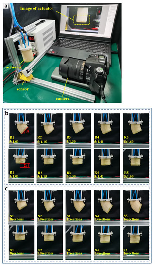
Figure 5.
Actuator motion characteristics test: (a) Bending and contraction testing device. Bending and contraction at 90 kPa with (b) different foaming ratios and (c) different actuator lengths. (θ and d are introduced in Section 4.1).
The output force determines the load capacity of the actuator. The output force of the end of the actuator during bending and contraction was measured with the setup shown in Figure 6. Specifically, the actuator was fixed horizontally to the bracket so that its end touched the bottom of the force transducer just as the bending output force was measured, at which point the transducer showed no indication. When negative pressure was applied, the end of the actuator was bent upward, and the sensor was squeezed. Measurements could be read directly from the digital display platform. When the contraction force was tested, the center of the actuator and digital display push-pull meter was aligned horizontally to minimize the error. The initial state was to keep the string in tension. Then, the same negative pressure was applied to all four chambers, and the positions of the actuator and push-pull gage were kept constant throughout the measurement process.
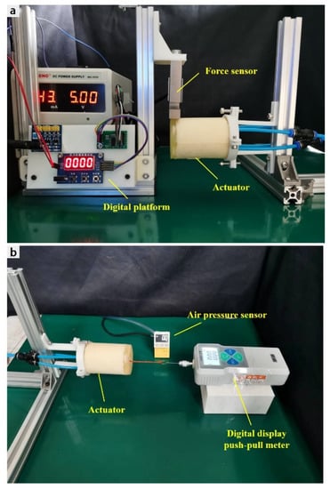
Figure 6.
Actuator output force test: (a) bending force testing device and (b) contraction force testing device.
3.2. Practical Application
A control system was developed to precisely control the air pressure for practical applications. Referring to the way in the literature [9], Figure 7a shows the control system and its structure. The best-performing actuators in terms of motion characteristics and output force were integrated in two sections to create a soft robot with eight air chambers in total, each of which could be controlled independently. Specifically, each air chamber was connected to two miniature three-way solenoid valves (JS0520L-DC6V), and one end of each solenoid valve was connected to a vacuum pump (JBL-550W) to provide a negative pressure drive. The two solenoid valves allowed each chamber to achieve three states: inflation, maintenance, and pressure regulation. Each air chamber was inflated and bent when both solenoids were open at the same time. When the second solenoid valve was closed, the airflow was disconnected, and the robot was in a motion-hold state. The second solenoid valve was reopened when the pressure needed to be increased further. To lower the air pressure, the first solenoid valve was closed after the second solenoid valve was opened, which allowed the air to flow through the speed control valve into the atmosphere. Figure 7b shows the three states and the control strategy. The airflow was controlled by a microcontroller (Arduino Mega 2560) and computer. A control program was written to drive each chamber. A sensor detected the air pressure of each chamber in real time, which was adjusted dynamically to achieve the target pressure.
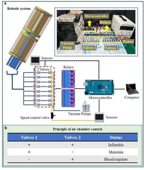
Figure 7.
Robotic system: (a) configuration of the control system and (b) principle of air chamber control.
The concept of modularity is often used in soft robotics. Four different experiments were conducted using the actuator module and control system constructed above: lifting heavy objects, grasping, walking, and making gestures. Two, three, or four modules were integrated to represent different soft robots. The bending and contraction performances of the actuators were tested to demonstrate the range of practical application.
4. Result
4.1. Motion and Output Force Characteristics
Figure 8 shows the relationships of the air pressure with the bending angle and contraction. We defined a parameter and as the bending angle and contraction distance of the actuator, respectively. When the actuator deforms under a given negative pressure and reaches stability, the bending angle refers to the angle between the end face of the actuator to the horizontal plane, and the contraction distance refers to the distance between the end face of the actuator to the end face at the initial 0 air pressure. Figure 8a,c shows that increasing the foaming multiplier (i.e., decreasing the density) caused the bending and contraction of the actuator to increase more with the air pressure. This is because a lower density increased the cell spacing, which reduced the interaction force between the cells and made them easier to squeeze when an external force was applied. However, this does not mean that a lower density was better; decreasing the density caused the actuator to become softer, which degraded its resilience and stability. This can be observed for the contraction curve of the actuator at a foaming multiplier of 5:1. The bending and contraction curves at this multiplier showed greater nonlinearity than at the other multipliers. The best bending and contraction characteristics of the actuator were obtained at a foaming multiplier of 5:1.15.
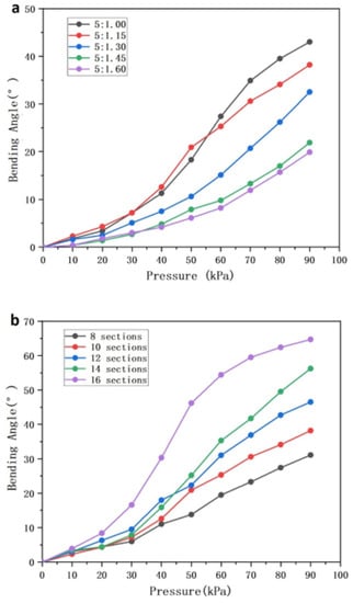
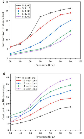
Figure 8.
Experimental results from bending and contraction tests: (a,b) relationship between the bending angle and air pressure and (c,d) relationship between the contraction distance and air pressure.
Figure 8b,d shows the bending and contraction curves of the actuators at different lengths. The bending angle and contraction showed a positive correlation with the input air pressure. This is because a longer air chamber increased the stroke by which the bellows could be contracted. Except for the 16-section actuator, which exhibited a large nonlinearity, all other sections showed some linearity. In particular, the 14-section actuator showed good linearity at 30–90 kPa compared with the other lengths. This corresponded to a total length of 71 mm for the actuator, which achieved a bending deformation of 56.2° and contraction of 34 mm in the length direction at 90 kPa. The contraction rate reached 47.9% of the original length, which is beneficial for operations in some special environments. Although the 16-section actuator had a greater bend angle and contraction distance, the linearity of the actuator was greatly affected; the actuator was misaligned on both end surfaces during compression, and the stability is reduced. Therefore, the length of the actuator was set to 71 mm.
Figure 9a shows the bending output force of the actuator with one, two, and three chambers activated. The output force increased with the air pressure, and the maximum output force of 3.35 N was generated with two chambers activated at 90 kPa. This was a significant increase from the output force of 1.75 N with one air chamber activated. The output force of the actuator with three air chambers activated is approximately equal to one air chamber activated when the air pressure is less than 50 kPa; as the air pressure increases, the output force increases more significantly to 3.1 N at 90 kPa. This is because when the actuator is activated in three air chambers, the two air chambers in parallel position provide a certain contraction force, which is not apparent until the air pressure is greater than 50 kPa. However, this is also the reason why the output force with three air chambers activated is less than the activation of two air chambers, because the contraction of the actuator limits the bending deformation.
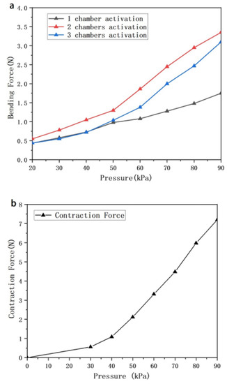
Figure 9.
Curve of output force vs. air pressure: (a) measured bending force when one, two, and three chambers of the actuator are activated; (b) measured contraction force when four chambers of the actuator are actuated.
Figure 9b shows the variation in the contraction output force of the actuator with the air pressure. The output force grows faster when the air pressure exceeds 45 kPa, which is in accordance with the actuator contraction becoming faster at the same stage. The actuator has a maximum contraction output force of 7.2 N at 90 kPa.
4.2. Practical Application
4.2.1. Lifting Experiment
A simple lifting device was built in accordance with the principle of leverage. As shown in Figure 10, two integrated actuators were placed vertically side by side, and they lifted the lever by contracting when negative pressure was applied, where F1 is the gravitational force of the load and F2 is the contraction force of the actuators. To demonstrate the device performance, gradually increase the mass of the weight in the small bowl at the front of the lever to increase the load until the small bowl fell to the table. The device easily lifted the lever above the horizontal line when no weights were added (Figure 10c). The lever gradually lowered as the weight was increased (Figure 10d,e). The device was able to lift over 255 g (Figure 10f), and the results proved the contraction performance of the actuator. For lifting operations in tight environments, more actuators can be integrated to improve the performance.
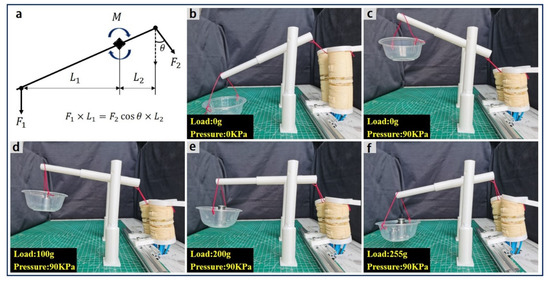
Figure 10.
Soft robot used as a lifting device: (a) mechanism force analysis diagram. (b,c) Lifting without a load; (d–f) lifting 50, 100, and 255 g loads at an air pressure of 90 kPa.
4.2.2. Gripping Experiment
Pneumatic soft grippers are a common form of soft robots. A foam soft gripper was fabricated with three integrated actuators and designed fixtures. To adapt the gripper to a wide range of object sizes, the fixture was designed to be adjustable in distance. Figure 11 shows that the fabricated gripper could grip objects of different shapes, sizes, and weights with different grasping methods. The results proved the bending performance of the actuator and that it can be applied to gripping tasks (Video S1). In addition, the soft gripper had a high load capacity and offered some cushioning protection, which can be used to grip various objects. As the foam actuator is based on contraction deformation driven by negative pressure, a new gripping mode is proposed: inward wrapping after gripping (Figure 11j–m). First, a suitable negative pressure is applied to bend the actuator to grip an object. Second, the actuator is gradually wrapped around the object as tight as possible depending on the actuator length and object size (Video S2). Compared with traditional inflatable actuators, this unique gripping mode of negative pressure-driven actuator and the reduced space it takes up when gripping objects allow it more flexibility and potential to be applied in tight environments such as space debris capture or fishing operations.
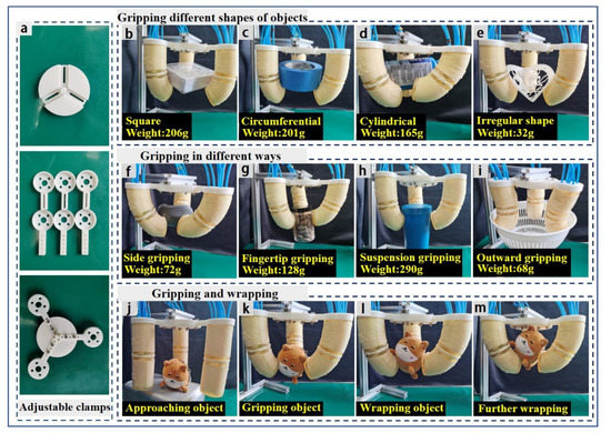
Figure 11.
Soft robot used as a soft gripper: (a) adjustable clamps; (b–e) gripping square, circular, cylindrical, and irregularly shaped objects; (f–i) gripping objects by the side, fingertips, suspension, and outward pressure; (j–m) gripping and wrapping plush toys.
4.2.3. Quadruped-Like Soft Robot
A quadruped-like soft robot was formed by using four actuator modules and 3D printed bases. Different air chambers were controlled to let the quadruped-like robot walk and avoid obstacles, as shown in Figure 12. Walking was achieved by controlling the section of each actuator that touched the ground. Specifically, negative pressure was applied to the two air chambers in the target direction of the two actuators in crossed positions to bend them and maintain contact with the bottom surface. The robot’s center of gravity shifts backward and creates a backward movement. Then, the pressure was removed to return the actuators to the initial state. This generated friction between the actuator and bottom surface, which caused the robot to move forward. Compared to the backward movement caused by the change in center of gravity, the forward movement is much greater, enables the robot to complete the walking process. In the test, the robot could move 40 mm per round (Video S3). Because of the contraction characteristics of the actuator, the robot could also perform specific obstacle avoidance maneuvers. For example, when there was an obstacle in front, the robot’s height could be lowered so that it could pass beneath. This required driving each air chamber to contract to the proper height. These results proved that the foam actuator has good synergistic controllability, which would be beneficial for field rescue and other applications in difficult environments.
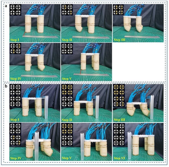
Figure 12.
Quadruped-like soft robot: (a) Walking process and the corresponding pumping sequence; (b) obstacle avoidance process and the corresponding pumping sequence (yellow: pumping, white: no air pressure).
4.2.4. Claw-Like Soft Robot
Finally, four actuators are combined to obtain a claw-like soft robot. As shown in Figure 13, the robot was able to signal numbers 1–5 as well as make the “okay” and “orchid finger” gestures. In addition, different fingers can cooperate to easily grip some objects. Because of the low cost of the actuator, this robot would be suitable for classroom teaching and science activities.
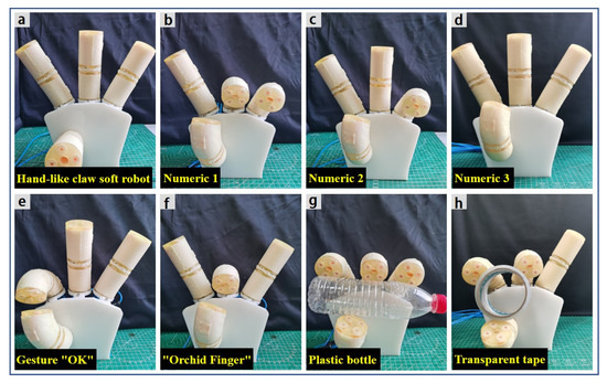
Figure 13.
(a) Claw-like soft robot; (b–d) gestures for numbers 1–3; (e,f) gestures for “okay” and “orchid finger”; (g,h) gripping a plastic bottle and transparent tape.
5. Discussion and Conclusions
A lightweight PU foam actuator driven by negative pressure has been successfully developed. The driving mechanism comprises four thin-walled bellows air chambers, which bend and contract to deform the wrapped foam body. The actuator is capable of two deformation modes: multi-angle bending and vertical contraction. The effects of the foaming multiplier and number of air chamber sections on the bending and contraction performances of the actuator were investigated. The experimental results showed that the bending angle and contraction distance of the actuator increased with a decreasing foaming multiplier and increasing number of air chamber sections. The bending angle and contraction distance of the actuator gradually increased as the air pressure was increased from 0 to 90 kPa. At 90 kPa, the actuator achieved a bending deformation of 56.2° and contraction distance of 34 mm. The output force experiment showed that the bending output force was greater with two chambers than with one or three chambers, and the maximum bending and contraction output forces were 3.35 and 7.2 N, respectively, at 90 kPa.
A comparison of this study with other soft actuators is presented in Table 3. Compared with existing foam soft actuators [30,32,33], the actuator in this study is superior in terms of deformation modes and application prospects. The foam actuator driven by negative pressure in this study had an output force of 7.2 N and a deformation effect of 47.9%, which is one of the largest among the soft pneumatic actuators based on the research by us and other scholars [6,9]. The foam actuator driven by negative pressure can achieve bending and contraction under reduced overall length without concern for the risk of overpressure which makes them more suitable for operation in tight environment. The designed actuator was integrated into various soft robots to demonstrate its wide applicability, including space debris capture, deep-sea exploration, field rescue, and classroom teaching.
Table 3.
A Comparison of Different Pneumatic Soft Actuators.
The design presented here has the following limitations: (1) The method of structure optimization through experiments has certain errors due to the defects in the manufacture of foam actuators; (2) the actuator lacks feedback and information exchange and cannot be regulated in time. Future work will focus on theoretical research and integrating flexible sensors to build more practical soft robots. Theoretical modeling based on the first generation of actuators will help us better optimize the structure and more accurately characterize the motion. Integrating flexible sensors into a soft robot system will allow it to measure stress and bending deformation.
Supplementary Materials
The following supporting information can be downloaded at: www.mdpi.com/article/10.3390/act11090245/s1, Video S1: Gripping objects of different shapes, sizes, and weights; Video S2: Gripping experiment with “inward wrapping after gripping”; Video S3: Quadruped-like soft robot for walking experiment.
Author Contributions
Conceptualization, Z.J., Z.Z. and Y.C.; methodology, Z.J., Z.Z. and Y.C.; software, Z.Z., Y.C., X.D. and C.S.; validation, Z.Z. and Y.C.; formal analysis, Z.Z.; investigation, Z.Z., Y.C., X.D. and C.S.; resources, Z.J. and Y.C.; writing—original draft preparation, Z.Z.; writing—review and editing, Z.Z., Z.J. and Y.Y.; supervision, Z.J., Y.Y. and F.L.; project administration, Z.J., Y.Y. and F.L.; funding acquisition, Z.J. and F.L. All authors have read and agreed to the published version of the manuscript.
Funding
This research was funded by Beijing Nova Program of China (No. 2020B00003127), Beijing Natural Science Foundation—Haidian Original Innovation Fund (No. L212047), National Natural Science Foundation of China (No. 52171149).
Institutional Review Board Statement
Not applicable.
Informed Consent Statement
Not applicable.
Data Availability Statement
Data are contained within the article.
Conflicts of Interest
The authors declare no conflict of interest.
References
- Hsiao, J.; Chang, J.; Cheng, C. Soft Medical Robotics: Clinical and Biomedical Applications, Challenges, and Future Directions. Adv. Robot. 2019, 33, 1099–1111. [Google Scholar] [CrossRef]
- Diodato, A.; Brancadoro, M.; Rossi, G.D. Soft Robotic Manipulator for Improving Dexterity in Minimally Invasive Surgery. Surg. Innov. 2018, 1, 69–76. [Google Scholar] [CrossRef]
- Payne, C.J.; Wamala, I.; Abah, C.; Thalhofer, T.; Saeed, M.; Salinas, D.B.; Horvath, M.A.; Vasilyev, N.V.; Roche, E.T.; Pigula, F.A.; et al. An Implantable Extracardiac Soft Robotic Device for the Failing Heart: Mechanical Coupling and Synchronization. Soft Robot. 2017, 4, 24–250. [Google Scholar] [CrossRef] [PubMed]
- Manfredi, L.; Capoccia, E.; Ciuti, G.; Cuschieri, A. A Soft Pneumatic Inchworm Double balloon (SPID) for colonoscopy. Sci. Rep. 2019, 9, 11109. [Google Scholar] [CrossRef] [PubMed]
- der Maur, P.A.; Djambazi, B.; Haberthür, Y.; Hörmann, P.; Kübler, A.; Lustenberger, M.; Sigrist, S.; Vigen, O.; Förster, J.; Achermann, F.; et al. RoBoa: Construction and Evaluation of a Steerable Vine Robot for Search and Rescue Applications. In Proceedings of the 2021 IEEE 4th International Conference on Soft Robotics (RoboSoft), New Haven, CT, USA, 12–16 April 2021; pp. 15–20. [Google Scholar]
- Wang, X.; Zhang, Q.; Shen, D.; Chen, J. A Novel Rescue Robot: Hybrid Soft and Rigid Structures for Narrow Space Searching. In Proceedings of the 2019 IEEE International Conference on Robotics and Biomimetics (ROBIO), Dali, China, 6–8 December 2019; pp. 2207–2213. [Google Scholar]
- Katzschmann, R.K.; DelPreto, J.; MacCurdy, R.; Rus, D. Exploration of underwater life with an acoustically controlled soft robotic fish. Sci. Robot. 2018, 3, eaar3449. [Google Scholar] [CrossRef] [PubMed]
- Li, G.; Chen, X.; Zhou, F.; Liang, Y.; Xiao, Y.; Cao, X.; Zhang, Z.; Zhang, M.; Wu, B.; Yin, S.; et al. Self-powered soft robot in the Mariana Trench. Nature 2021, 591, 66–71. [Google Scholar] [CrossRef] [PubMed]
- Zhang, B.; Fan, Y.; Yang, P.; Cao, T.; Liao, H. Worm-Like Soft Robot for Complicated Tubular Environments. Soft Robot. 2019, 6, 399–413. [Google Scholar] [CrossRef]
- Kim, W.; BYUN, j.; Kim, J.; Chol, W.; Jakobsen, K.; Jakobsen, J.; Lee, D.; Cho, K. Bioinspired dual-morphing stretchable origami. Sci. Robot. 2019, 4, eaay3493. [Google Scholar] [CrossRef]
- Argiolas, A.; Mac Murray, B.; Meerbeek, I.; Whitehead, J.; Whitehead, E.; Mazzolai, B.; Shepherd, R. Sculpting Soft Machines. Soft Robot. 2016, 3, 101–108. [Google Scholar] [CrossRef]
- Yamada, Y. Feasibility Study on Botanical Robotics: Ophiocordyceps-like Biodegradable Laminated Foam-Based Soft Actuators With Germination Ability. IEEE Robot. Autom. Lett. 2021, 6, 3777–3784. [Google Scholar] [CrossRef]
- Bern, J.; Kumagai, G.; Coros, S. Fabrication, modeling, and control of plush robots. In Proceedings of the 2017 IEEE/RSJ International Conference on Intelligent Robots and Systems (IROS), Vancouver, BC, Canada, 24–28 September 2017; pp. 3739–3746. [Google Scholar]
- Walker, J.; Zidek, T.; Harbel, C.; Yoon, S.; Strickland, F.S.; Kumar, S.; Shin, M. Soft Robotics: A Review of Recent Developments of Pneumatic Soft Actuators. Actuators 2020, 9, 3. [Google Scholar] [CrossRef]
- Kim, J.; Kim, J.W.; Kim, H.C.; Zhai, L.; Ko, H.; Muthoka, R. Review of Soft Actuator Materials. Int. J. Precis. Eng. Manuf. 2019, 20, 2221–2241. [Google Scholar] [CrossRef]
- Schmitt, F.; Piccin, O.; Barbé, L.; Bayle, B. Soft Robots Manufacturing: A Review. Front. Robot. AI 2018, 5, 84. [Google Scholar] [CrossRef]
- El-Atab, N.; Mishra, R.B.; Al-Modaf, F.; Joharji, L.; Alsharif, A.A.; Alamoudi, H.; Diaz, M.; Qaiser, N.; Hussain, M.M. Soft Actuators for Soft Robotic Applications: A Review. Adv. Intell. Syst. 2020, 2, 2000128. [Google Scholar] [CrossRef]
- Fei, Y.; Wang, J.; Pang, W. A Novel Fabric-Based Versatile and Stiffness-Tunable Soft Gripper Integrating Soft Pneumatic Fingers and Wrist. Soft Robot. 2019, 6, 1–20. [Google Scholar] [CrossRef] [PubMed]
- Hao, Y.; Liu, Z.; Liu, J.; Fang, X.; Fang, B.; Nie, S.; Guan, Y.; Sun, F.; Wang, T.; Wen, L. A soft gripper with programmable effective length, tactile and curvature sensory feedback. Smart Mater. Struct. 2020, 29, 035006. [Google Scholar] [CrossRef]
- Heung, K.; Tong, R.; Lau, A.; Li, Z. Robotic Glove with Soft-Elastic Composite Actuators for Assisting Activities of Daily Living. Soft Robot. 2019, 6, 289–304. [Google Scholar] [CrossRef]
- Lessard, S.; Pansodtee, P.; Robbins, A.; Trombadore, J.M.; Kurniawan, S.; Teodorescu, M. A Soft Exosuit for Flexible Upper-Extremity Rehabilitation. IEEE Trans. Neural Syst. Rehabil. Eng. 2018, 26, 1604–1617. [Google Scholar] [CrossRef]
- Guan, Q.; Sun, J.; Liu, Y.; Wereley, N.M.; Leng, J. Novel Bending and Helical Extensile/Contractile Pneumatic Artificial Muscles Inspired by Elephant Trunk. Soft Robot. 2020, 7, 597–614. [Google Scholar] [CrossRef]
- Al-Fahaam, H.; Nefti-Meziani, S.; Theodoridis, T.; Davis, S. The Design and Mathematical Model of a Novel Variable Stiffness Extensor-Contractor Pneumatic Artificial Muscle. Soft Robot. 2018, 5, 576–591. [Google Scholar] [CrossRef]
- Kastor, N.; Mukherjee, R.; Cohen, E.; Vikas, V.; Trimmer, B.; White, R. Design and Manufacturing of Tendon-Driven Soft Foam Robots. Robotica 2020, 38, 88–105. [Google Scholar] [CrossRef]
- Donatelli, C.M.; Serlin, Z.T.; Echols-Jones, P.; Scibelli, A.E.; Cohen, A.; Jeanne-Marie, C.; Rozen-Levy, S.; Buckingham, D.; White, R.; Trimmer, B.A. Soft foam robot with caterpillar-inspired gait regimes for terrestrial locomotion. In Proceedings of the 2017 IEEE/RSJ International Conference on Intelligent Robots and Systems (IROS), Vancouver, BC, Canada, 24–28 September 2017; pp. 476–481. [Google Scholar]
- King, J.P.; Bauer, D.; Schlagenhauf, C.; Chang, K.; Moro, D.; Pollard, N.; Coros, S. Design, Fabrication, and Evaluation of Tendon-Driven Multi-Fingered Foam Hands. In Proceedings of the 2018 IEEE-RAS 18th International Conference on Humanoid Robots (Humanoids), Beijing, China, 6–9 November 2018; pp. 1–9. [Google Scholar]
- Somm, L.; Hahn, D.; Kumar, N.; Coros, S. Expanding Foam as the Material for Fabrication, Prototyping and Experimental Assessment of Low-Cost Soft Robots With Embedded Sensing. IEEE Robot. Autom. Lett. (RAL) 2019, 4, 761–768. [Google Scholar] [CrossRef]
- Mac Murray, B.C.; An, X.; Robinson, S.S.; van Meerbeek, I.M.; O’Brien, K.W.; Zhao, H.; Shepherd, R.F. Poroelastic Foams for Simple Fabrication of Complex Soft Robots. Adv. Mater. 2015, 27, 6334–6340. [Google Scholar] [CrossRef]
- Futran, C.C.; Ceron, S.; Mac Murray, B.C.; Shepherd, R.F.; Petersen, K.H. Leveraging fluid resistance in soft robots. In Proceedings of the 2018 IEEE International Conference on Soft Robotics, Livorno, Italy, 24–28 April 2018; pp. 473–478. [Google Scholar]
- Peters, J.; Anvari, B.; Chen, C.; Lim, Z.; Wurdemann, H.A. Hybrid fluidic actuation for a foam-based soft actuator. In Proceedings of the IEEE/RSJ International Conference on Intelligent Robots and Systems (IROS), Las Vegas, NV, USA, 24–30 October 2020; pp. 8701–8708. [Google Scholar]
- Van Meerbeek, I.M.; Mac Murray, B.C.; Kim, J.W.; Robinson, S.S.; Zou, P.X.; Silberstein, M.N.; Shepherd, R.F. Morphing Metal and Elastomer Bicontinuous Foams for Reversible Stiffness, Shape Memory, and Self-Healing Soft Machines. Adv. Mater. 2016, 28, 2801–2806. [Google Scholar] [CrossRef]
- Robertson, M.A.; Paik, J. New soft robots really suck: Vacuum-powered systems empower diverse capabilities. Sci. Robot. 2017, 2, eaan6357. [Google Scholar] [CrossRef]
- Joe, S.; Totaro, M.; Wang, H.; Beccai, L. Development of the Ultralight Hybrid Pneumatic Artificial Muscle: Modelling and optimization. PLoS ONE 2021, 16, e0250325. [Google Scholar] [CrossRef]
- Alzoubi, M.F.; Al-Hallaj, S.; Abu-Ayyad, M. Modeling of Compression Curves of Flexible Polyurethane Foam with Variable Density, Chemical Formulations and Strain Rates. J. Solid Mech. 2014, 6, 82–97. [Google Scholar]
- Jeong, K.Y.; Cheon, S.S.; Munshi, M.B. A constitutive model for polyurethane foam with strain rate sensitivity. J. Mech. Sci. Technol. 2012, 26, 2033–2038. [Google Scholar] [CrossRef]
- Li, Y. Multi-axial Mechanical Properties Test of Energy-Absorbing Polyurethane Foam. Master’s Thesis, South China University of Technology, Guangzhou, China.
Publisher’s Note: MDPI stays neutral with regard to jurisdictional claims in published maps and institutional affiliations. |
© 2022 by the authors. Licensee MDPI, Basel, Switzerland. This article is an open access article distributed under the terms and conditions of the Creative Commons Attribution (CC BY) license (https://creativecommons.org/licenses/by/4.0/).