Abstract
In this study, we present an innovative approach to risk assessment for rear-end collision avoidance using a cooperation concept for an autonomous lane change system. A Kalman filter is designed to estimate the longitudinal acceleration and predict the relative longitudinal position, velocity, and acceleration. Risk assessment is performed using the predicted motion of the object vehicle in the target lane. The cooperation concept is proposed to improve the flexibility of the lane change. If the risk assessment for the lane change indicates collision risk, the cooperativeness of the driver of the object vehicle is determined. If the driver of the object vehicle is regarded as a cooperative driver, within the original lane, the ego vehicle moves toward the target lane in preparation for the lane change. Subsequently, as soon as the risk assessment indicates that there is no collision risk, the lane change is performed. Thus, unlike conventional methods, the autonomous lane change using the proposed risk assessment can be initiated. Furthermore, the proposed risk assessment using cooperation concept is more flexible compared with previous methods for autonomous lane change in cluttered traffic.
1. Introduction
In automotive industries, risk assessment using environment sensors (e.g., vision, radar, global positioning system (GPS), etc.) is the main focus to prevent drivers from road accidents. Various risk assessment methods for collision avoidance have been researched [1,2]. Conditions for collision avoidance were studied using vehicle kinematics [3]. In addition, a risk assessment method was developed for determining the collision risk by tracking vehicles in critical regions and computing the time to collision [4]. Risk assessment methods were designed based on deterministic models [3,4], and several approaches were proposed using probabilistic models. A risk assessment method was proposed using Hidden Markov Models and Gaussian processes [5]. Path planning methods were developed for automotive collision avoidance [6]. In [7], a method was designed to propagate the known error covariance matrix of the current pose of an ego vehicle by considering local approximations of the predicted trajectory for risk assessment. A probabilistic threat assessment method was proposed to predict all possible types of collisions for multi-vehicle traffic [8]. In [9], a risk assessment methodology that integrates a network-level collision estimate with a vehicle-based risk estimate in real time under the joint framework of interaction-aware motion models and dynamic Bayesian network was developed. Furthermore, to guarantee collision avoidance in multi-scenarios for autonomous vehicles, a new risk assessment based decision-making algorithm was developed [10].
When drivers attempt lane changes, collisions with vehicles in the target lane is the main cause of traffic accidents [11]. Hence, the autonomous lane change system (LXS) has been studied to reduce traffic accidents during lane changes [12,13,14]. The risk assessment methods in [3,4,5,7,8,9,10] only determine the present-time collision risk for the lane change, and a lane change can only be performed there is sufficient time to secure the available target-lane space. Thus, it is difficult for these methods to be applied to the autonomous LXS in cluttered traffic. Consequently, a risk assessment suited for the autonomous LXS is necessary.
In this study, we present an innovative approach to risk assessment using a cooperation for rear-end collision avoidance concept for autonomous LXS. A Kalman filter is designed to estimate longitudinal acceleration and predict the relative longitudinal position, velocity, and acceleration. Using the predicted motion of the object vehicle in the target lane, risk assessment is performed, and a cooperation concept is used to improve the flexibility of the lane change. If the risk assessment for the lane change indicates collision risk, the cooperativeness of the driver of the object vehicle is determined. The driver of the object vehicle is indexed as a cooperative driver (CD) or non-cooperative driver (NCD) by using conditions based on the relative longitudinal acceleration and collision-free time when the collision assessment for the lane change becomes safe. If the driver of the object vehicle is regarded as a CD, within the original lane, the ego vehicle moves toward the target lane in preparation for the lane change. Until the lane change becomes safe, the ego vehicle is controlled to keep its lateral position within the original lane. As soon as the risk assessment determines the lane change to be safe, the lane change is performed. Thus, unlike the conventional methods, the autonomous lane change using the proposed risk assessment can be initiated in advance. Furthermore, the proposed risk assessment using the cooperation concept is more flexible compared with previous methods for autonomous lane changes in the cluttered traffic. The proposed method is validated using computational simulation results via CarSim and MATLAB/Simulink.
2. Risk Assessment for Autonomous LXS
2.1. Risk Assessment Strategy for Autonomous LXS
The strategy of the autonomous LXS is shown in Figure 1. is the sampling time of the risk assessment system, and k represents the discrete time index. The LXS strategy is divided into four stages. At of stage 1, a driver switches on a switch to transfer the intention to the lane change. In stage 1, the lane keeping system (LKS) designed in [15] maintains the center position of the vehicle in the original lane while risk assessment is performed. The lane change starts at . Stage 2 is a section from the initiation of the lane change () to instant () before entering the target lane. Stage 3 is a section from instant () immediately after entering a target lane to instant () where the vehicle settles in the target lane. In stage 4, LKS keeps the vehicle within the target lane for a while. After completing stage 4, LXS is switched off, and the authority of the steering wheel is given to the driver. The risk assessment is performed at all stages (1–4).
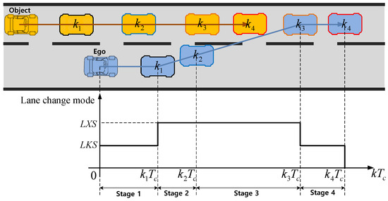
Figure 1.
Strategy of autonomous LXS.
2.2. Coordinates of Vehicle for Risk Assessment
In Figure 2, , , , and denote the longitudinal distance, latitudinal distance, safety margin to rear direction, and safety margin to front direction, respectively. If the object vehicle is behind the ego vehicle, the relative distance between the ego vehicle and object vehicle is negative; that is, . The origin of the coordinates is the center of gravity (CG) of the ego vehicle. Note that we do not consider as we are interested in the risk of only the rear object vehicle during lane change. The relative velocity between the ego and object vehicles, , is as follows:
where and are the longitudinal velocities of the object and ego vehicles, respectively. is the distance depending on a relative velocity between the ego and object vehicles, . is defined as follows.
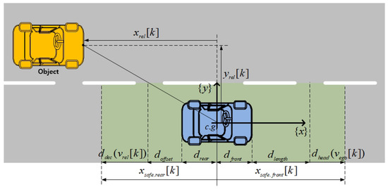
Figure 2.
Definition of vehicle coordinates.
If is positive, is the stopping distance when the object vehicle decelerates up to ‘’ by maximum deceleration, . Otherwise, is 0. That is, we consider only when the object vehicle is faster than the ego vehicle. The safety margin is defined as follows:
where is the distance from CG to the rear part of the ego vehicle, and is the minimum safety margin distance. Generally, the risk assessment focuses on rear-end collisions during lane changes [16]. Thus, in this paper, we will focus on the risk assessment for rear-end collisions.
3. Kalman Filter Design
In this study, we assume that the object vehicle moves with relatively constant acceleration. The state vector, , is defined as follows:
where , , and are the relative longitudinal distance, velocity and acceleration between the ego and object vehicles. The discrete time model of is stated as follows:
where the following is the case.
The Kalman filter is designed to estimate the longitudinal acceleration and to predict the relative longitudinal position, velocity, and acceleration as follows.
The observer gain L is obtained by using the Ricatti equation in [17] as follows.
Using the constant acceleration model (5) and Kalman filter (7), the relative longitudinal position, velocity, and acceleration can be predicted. Q and R matrices represent the corresponding covariance of , which are system noise and measurement noise, respectively, from radar data under the assumption that they both are white and Gaussian with known covariances.
4. Risk Assessment Using Cooperation Concept
After the autonomous LXS is initiated, the collision risk of the object vehicle in the target lane is determined at every sampling time using the lane change trajectory as shown in Figure 1. In this section, we describe the overall risk assessment algorithm of the autonomous LXS.
4.1. Index for Risk Assessment
The index for judging the collision risk is a ratio of the safety margin distance to the relative longitudinal distance. Using the constant acceleration model (5) and Kalman filter (7), the relative distance and safety margin at can be predicted as follows.
Using (9), the indices and for judging the collision risk at present times k and are defined as follows.
4.2. Conditions for Collision-Free
To assess the collision risk, we define two safety conditions. The first condition is that all indices at k and are greater than or equal to 1, which are represented as follows.
This indicates that the object vehicle is far from the ego vehicle at k and .
Figure 3 presents the case study for the relative distance and the safety margin at present time . is the CG of the ego vehicle. , , , and are the relative distances at k and and safety margin at k and , respectively. Figure 3a,b show when it is safe to perform lane changes and when there is collision risk in lane change, respectively. Figure 3c shows that the collision risk related to the index is safe; however, it predicts that there is collision risk at the local maximum point of the relative distance. Therefore, we add a second condition to determine the collision risk at the local maximum point. The time at local maximum points appearing during can be calculated as follows.
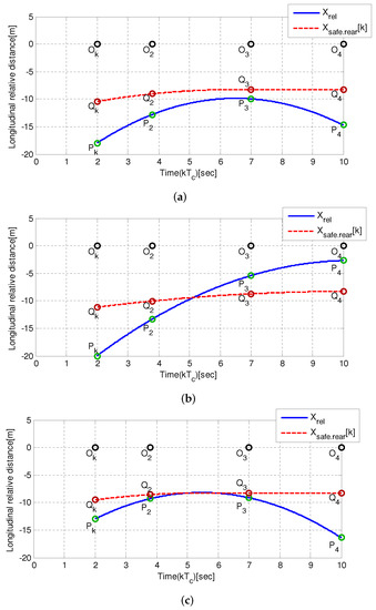
Figure 3.
Case study for the relative distance and safety margin. (a) Case 1: The collision risk is safe. (b) Case 2: The collision risk is danger. (c) Case 3: Need to check the local maximum point.
If is not present in the interval , it is safe to perform lane changes. Otherwise, the safe index at the local maximum should be calculated using the relative distance and safety margin at . If the relative distance at is less than or equal to the safety margin at , it is safe to perform lane changes. If not, there is a collision risk.
4.3. Risk Assessment Using the Cooperation Concept
This section describes how risk assessment is performed using the cooperation concept according to the strategy of the autonomous LXS, as shown in Figure 1. The description of the stages is shown in Table 1. For the flexibility of the autonomous lane change, we will introduce a cooperation concept in risk assessment. In stage 1, LKS maintains the vehicle within the original lane while risk assessment is performed. The system operates the steering command to change the lane in stage 2 while determining collision risks. If risk assessment indicates that it is safe to perform lane change, the system performs the lane change maneuver. If not, the system determines whether the driver of the object vehicle is cooperative for lane changes of the ego vehicle. To determine the cooperativeness of the driver of the object vehicle, two conditions are proposed. The first condition is to determine the relative acceleration between the object and ego vehicles. If the relative acceleration is positive (that is, the acceleration of the object vehicle is higher than that of the ego vehicle), we regard the driver of the object vehicle as the NCD. Otherwise, we consider the second condition to determine the time when risk assessment indicates that it is safe to perform the lane change; that is, we determine the time when the predicted relative distance is smaller than or equal to the safety margin; after the initial time, the predicted relative distance is smaller than the safety margin. is the time when risk assessment indicates that it is safe to perform the lane change. can be obtained by calculating the point of intersection between the predicted relative distance under the assumption that acceleration is constant and the safety margin is met, except for , as follows.

Table 1.
Description of stages.
For the case study, a calculation of the collision free time is shown in Figure 4. Note that is zero if the relative velocity is negative in (2). The red square box in Figure 4 indicates that . converges to zero as decreases. Consequently, the safety margin gradually decreases until . If the following is the case:
where is the threshold to determine the cooperation, the driver of the rear object vehicle is regarded as the CD. Failing that, the opposite is true. Condition (14) indicates that the lane change is expected to become safe soon. If the driver of the object vehicle is the CD, the system actuates the ego vehicle toward the target lane up to before entering the target lane, and then the position is maintained while counting the hold count (). and D denote the lane and vehicle widths, respectively. If is greater than the threshold (), the object vehicle is judged as the NCD. If the object vehicle is the NCD, the system returns the ego vehicle to the center position in the original lane, holds the position, and counts the hold count (). The system is canceled if is greater than the threshold . If there is no collision risk, the system operates the steering command to change the lane in stage 3. Failing that, the system actuates the ego vehicle to the position in the original lane, holds the position, and counts the hold count . The system is canceled if is greater than . In Stage 4, the system performs the lane change in the target lane and then the process is completed. Figure 5 shows the flow chart for risk assessment according to the LXS strategy.
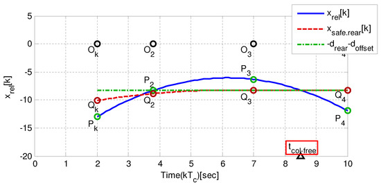
Figure 4.
Case study of the collision free time calculation.
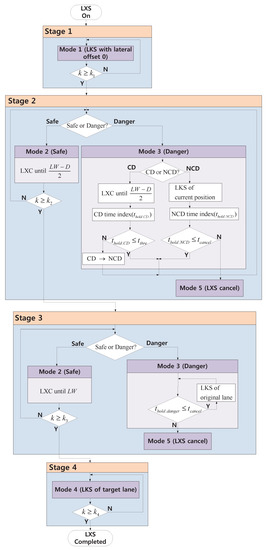
Figure 5.
Flow chart for risk assessment according to the strategy of LXS.
5. Simulation Results
The proposed risk assessment system was evaluated using CarSim and MATLAB/Simulink. The lateral controller proposed in [15] was implemented using the S-function. The risk assessment of the ego vehicle was implemented using the S-function. The threshold of the hold time (, ) was set to 10 s, and the sampling rate of the controller was set to 100 Hz.
5.1. Estimation Performance of Kalman Filter
The simulations and experiments were tested to validate the estimation performance of the Kalman filter (7) for risk assessment. The relative longitudinal position, velocity, and acceleration were estimated with the use of the relative longitudinal position by the Kalman filter (7). Figure 6 shows the estimation performances of the Kalman filter in the simulations and experiments. The blue solid and red dotted lines represent the measured and estimated data, respectively. In the simulations, the position, velocity, and acceleration were estimated well by the Kalman filter. The estimation errors were less than 0.3% in position, velocity, and acceleration. In the experiments, it is observed that the position and velocity were estimated well. The estimation errors were less than 0.5% in terms of position and velocity. Thus, we can expect that acceleration can be estimated well by the Kalman filter from these results of the simulation and experimental results.
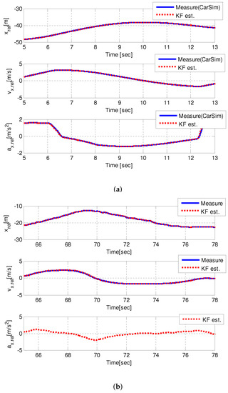
Figure 6.
Estimation performances of the Kalman filter. (a) CarSim. (b) Experiments.
5.2. Simulation for the Risk Assessment
In the simulations, a straight three-lane road was used. The ego and object vehicles traveled in the second and third lanes, respectively. The two cases were simulated. For these cases, two methods were tested as follows: (1) Method 1 involved risk assessments without the cooperation concept, and (2) Method 2 (proposed method) involved a risk assessment with the cooperation concept. The time, , of the stage was set to 3 s.
In both cases, the drivers of the ego vehicles transferred the lane change intention to the autonomous system at 1 s. Subsequently, the system immediately took over the control. Lane keeping was performed by the autonomous system in the original lane over a 2 s interval (from 1 to 3 s).
Case 1: The initial relative longitudinal distance between the ego and object vehicles was 25 m ( m). The longitudinal velocities of the ego and object vehicles are shown in Figure 7. The ego vehicle had a constant longitudinal velocity of 80 kph, and the initial longitudinal velocity of object vehicle was 90 kph. The longitudinal velocity of object vehicle decelerated constantly to 76 kph in the range of 3–10.5 s. Figure 8 shows the simulation results of case 1. The autonomous LXS was initiated after 1 s. In stage 1 (1–3 s), LKS maintained the center position of the vehicle in the original lane while risk assessment was performed. The collision risk index in Figure 8c indicates 2, which means risk from 1 to 11 s. Thus, in method 1, the ego vehicle lane change started at 11 s because the collision risk index indicated a safe situation. At stage 2 (from 3 s), the driver of the object vehicle was evaluated for CD. From 3 to 4 s, the driver of the object vehicle was regarded as NCD, and the ego vehicles were kept maintained in the centerline of the original lane by the autonomous system. From 4 to 11 s, Figure 8c,d show that the autonomous system regarded the driver of the object vehicles as CD, even though there was a collision risk. Thus, in method 2, LXS with the cooperation concept controlled the steering wheel in advance to move the ego vehicle toward the target lane up to in Figure 8b. Consequently, the LXS with the cooperation concept reached the target lane approximately 1–2 s faster than the LXS without the cooperation concept. Detailed information is shown in the video clip (https://youtu.be/3V5193aayxk, accessed on 1 February 2022). The red car in method 1 changed lanes without the cooperation concept, and the green car in method 2 changed lanes with the cooperation concept. It is shown that the green car in method 2 finished the lane change in advance compared with the red car in method 1.
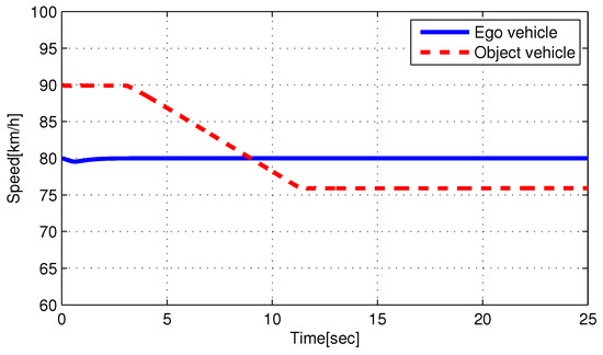
Figure 7.
Velocities of ego and object vehicle of case 1.
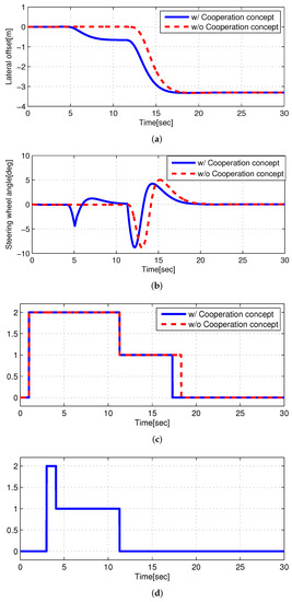
Figure 8.
Simulation Results of case 1. (a) Lateral offset (to the center line of the original lane) of the ego vehicle. (b) Steering wheel angle of the ego vehicle. (c) Collision risk. 1: safe; 2: danger. (d) Cooperation index of method 2. 1: CD; 2: NCD.
Case 2: The initial relative longitudinal distance between the ego and object vehicles was shorter than that in case 1 ( m). Figure 9 shows the longitudinal velocities of the ego and object vehicles, respectively. The longitudinal velocity of the ego vehicle was the same as that in case 1 (80 kph). However, the object vehicle had a different longitudinal velocity and acceleration. The object vehicle started at 85 kph and constantly decelerated to 65 kph during the interval of 3–8 s. The simulation results of case 2 are shown in Figure 10. The autonomous LXS was initiated after 1 s. In stage 1 (1–3 s), LKS maintained the center position of the vehicle in the original lane, while risk assessment was performed. The collision risk index in Figure 10c presents a value of 2, which indicates a risk from 3 to 7.5 s. Thus, in method 1, the ego vehicle started to change lanes at 7.5 s because the risk assessment indicated a safe situation. In stage 2 (from 3 s), the driver of the object vehicle was evaluated for CD. In method 2, from 3 to 3.5 s, the driver of the object vehicle was regarded as NCD in Figure 10d, and the ego vehicles were maintained in the centerline of the original lane. Although there was collision risk from 4 to 11 s, the driver of the object vehicle was regarded as CD. Thus, in method 2, the ego vehicle moved toward the target lane. Subsequently, the ego vehicle maintained the position before the risk assessment revealed that it was safe to perform the lane change. Consequently, Figure 10b shows that the LXS with the cooperation concept controlled the steering wheel in advance to move the position immediately before entering the target lane; this was due to the judgement that the driver of the object vehicles was regarded as CD even though there was collision risk. Therefore, the LXS with the cooperation concept reached the target lane approximately 1–2 s faster than LXS without the cooperation concept. The details are included in the video clip (https://youtu.be/I1bq4d7DuAM, accessed on 1 February 2022). The red car in method 1 changed lanes without the cooperation concept. The green car in method 2 changed lanes with the cooperation concept. The green car in method 2 completed the lane change earlier compared with the red car in method 1.
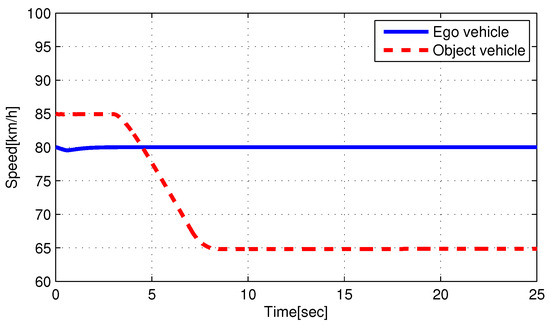
Figure 9.
Velocities of ego and object vehicle of case 2.
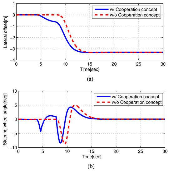
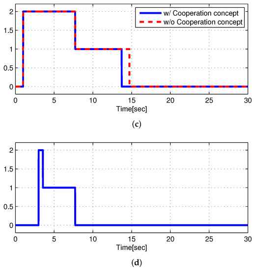
Figure 10.
Simulation Results of case 2. (a) Lateral offset (to the center line of the original lane) of the ego vehicle. (b) Steering wheel angle of the ego vehicle. (c) Collision risk. 1: safe; 2: danger. (d) Cooperation index of method 2. 1: CD; 2: NCD.
6. Conclusions
Using the cooperation concept, we developed the risk assessment method for the rear-end collision avoidance of the autonomous LXS. The Kalman filter was designed to estimate longitudinal acceleration and to predict the relative longitudinal position, velocity, and acceleration. Using the predicted motion of the object vehicle in the target lane, a risk assessment was performed. The cooperation concept was proposed to improve the flexibility of lane change. The proposed method was validated using computational simulation results via CarSim and MATLAB/Simulink. The estimation performance of the Kalman filter was validated. It was observed that the proposed risk assessment can reduce the time for the lane change.
Two drawbacks of the proposed method are the uncertainty of the maximum deceleration and the absence of threshold distance in the lateral direction. The safety margin depends on the maximum deceleration. Many safety experts use 0.47 g as the maximum deceleration that is safe for the average driver to maintain control, that is good for excellent tires, and that is good for dry surfaces. Actually, the maximum deceleration varies according to various conditions such as the vehicle type, the tire condition, and the road’s condition [18]. Thus, the maximum acceleration should be chosen conservatively. However, in this case, the safety margin may decrease. Furthermore, only rear-end collision was considered. Risk assessment can be improved with the consideration of the threshold distance in the lateral direction. In future works, risk assessment prediction will be studied with the consideration of the maximum deceleration variation and the threshold distance in lateral directions.
Author Contributions
Y.S.S. and W.K. designed the algorithm and developed the simulation; Y.S.S. and W.K. provided guidance in designing the algorithm; Y.S.S. and W.K. verified the simulation model and results. All authors have read and agreed to the published version of the manuscript.
Funding
This research was supported by Basic Science Research Program through the National Research Foundation of Korea (NRF) funded by the Ministry of Education (2021R1A6A1A03043144).
Institutional Review Board Statement
Not applicable.
Informed Consent Statement
Not applicable.
Data Availability Statement
Not applicable.
Conflicts of Interest
The authors declare that no conflict of interest.
References
- Dahl, J.; de Campos, G.R.; Olsson, C.; Fredriksson, J. Collision avoidance: A literature review on threat-assessment techniques. IEEE Trans. Intell. Veh. 2018, 4, 101–113. [Google Scholar] [CrossRef]
- Hamid, U.Z.A.; Saito, Y.; Zamzuri, H.; Rahman, M.A.A.; Raksincharoensak, P. A review on threat assessment, path planning and path tracking strategies for collision avoidance systems of autonomous vehicles. Int. J. Veh. Auton. Syst. 2013, 14, 134–169. [Google Scholar] [CrossRef]
- Jula, H.; Kosmatopoulos, E.B.; Ioannou, P.A. Collision avoidance analysis for lane changing and merging. IEEE Trans. Veh. Technol. 2000, 46, 2295–2308. [Google Scholar] [CrossRef] [Green Version]
- Hillenbrand, J.; Spieker, A.M.; Kroschel, K. A multilevel collision mitigation approach its situation assessment, decision making, and performance tradeoffs. IEEE Trans. Intell. Transp. Syst. 2006, 7, 528–540. [Google Scholar] [CrossRef]
- Laugier, C.; Paromtchik, I.E.; Perrollaz, M.; Yong, M.; Yoder, J.-D.; Tay, C.; Mekhnacha, K.; Nègre, A. Probabilistic analysis of dynamic scenes and collision risks assessment to improve driving safety. IEEE Intell. Transp. Syst. Mag. 2006, 3, 4–19. [Google Scholar] [CrossRef] [Green Version]
- Madås, D.; Nosratinia, M.; Keshavarz, M.; Sundström, P.; Philippsen, R.; Eidehall, A.; Dahlén, K.M. On path planning methods for automotive collision avoidance. In Proceedings of the 2013 IEEE Intelligent Vehicles Symposium (IV), Gold Coast, QLD, Australia, 23–26 June 2013; pp. 931–937. [Google Scholar]
- Houénou, A.; Bonnifait, P.; Cherfaoui, V. Risk assessment for collision avoidance systems. In Proceedings of the 17th International IEEE Conference on Intelligent Transportation Systems (ITSC), Qingdao, China, 8–11 October 2014; pp. 386–391. [Google Scholar]
- Kim, B.J.; Son, Y.S.; Yi, K. Probabilistic threat assessment with environment description and rule-based multi-traffic prediction for integrated risk management system. In Proceedings of the 2015 IEEE Intelligent Vehicles Symposium (IV), Seoul, Korea, 28 June–1 July 2015; pp. 642–647. [Google Scholar]
- Katrakazas, C.; Quddus, M.; Chen, W.H. A new integrated collision risk assessment methodology for autonomous vehicles. Accid. Anal. Prev. 2019, 127, 61–79. [Google Scholar] [CrossRef] [PubMed] [Green Version]
- Li, G.; Yang, Y.; Zhang, T.; Qu, X.; Cao, D.; Cheng, B.; Li, K. Risk assessment based collision avoidance decision-making for autonomous vehicles in multi-scenarios. Transp. Res. Part C Emerg. Technol. 2021, 122, 102820. [Google Scholar] [CrossRef]
- National Highway Traffic Safety Administration. Traffic Safety Facts 2005; Department of Transportation: Washington, DC, USA, 2006. [Google Scholar]
- Fang, C.-Y.; Chen, S.-W.; Fuh, C.-S. Automatic change detection of driving environments in a vision-based driver assistance system. IEEE Trans. Neural Netw. 2003, 14, 646–657. [Google Scholar] [CrossRef] [PubMed]
- Schubert, R.; Schulze, K.; Wanielik, G. Situation assessment for automatic lane-change maneuvers. IEEE Trans. Intell. Transp. Syst. 2010, 11, 607–616. [Google Scholar] [CrossRef]
- Whitsitt, S.; Sprinkle, J. A hybrid controller for autonomous vehicle lane changing with epsilon dragging. In Proceedings of the 2014 American Control Conference, Portland, OR, USA, 4–6 June 2014; pp. 5307–5312. [Google Scholar]
- Hwang, Y.; Kang, C.M.; Kim, W. Robust nonlinear control using barrier Lyapunov function under lateral offset error constraint for lateral control of autonomous vehicles. IEEE Trans. Intell. Transp. Syst. 2022, 23, 1565–1571. [Google Scholar] [CrossRef]
- Chen, C.; Liu, X.; Chen, H.H.; Li, M.; Zhao, L. A rear-end collision risk evaluation and control scheme using a Bayesian network model. IEEE Trans. Intell. Transp. Syst. 2018, 20, 264–284. [Google Scholar] [CrossRef]
- Franklin, G.F.; Powell, J.D.; Workman, M.L. Digital Control of Dynamic Systems; Addison-Wesley: Boston, MA, USA, 1998. [Google Scholar]
- Bokare, P.S.; Maurya, A.K. Acceleration-deceleration behaviour of various vehicle types. Transp. Res. Procedia 2017, 25, 4733–4749. [Google Scholar] [CrossRef]
Publisher’s Note: MDPI stays neutral with regard to jurisdictional claims in published maps and institutional affiliations. |
© 2022 by the authors. Licensee MDPI, Basel, Switzerland. This article is an open access article distributed under the terms and conditions of the Creative Commons Attribution (CC BY) license (https://creativecommons.org/licenses/by/4.0/).