Abstract
In order to solve the complexity of the structure, assembly process, component contact state and working process of the propellant actuator by conventional methods, a novel design method based on theoretical and numerical analysis was proposed. The internal ballistic model of the propellant actuator was established based on the classical internal ballistic theory, and the pressure–time characteristic curve of the propellant gas was then obtained. According to the characteristic curve, the dynamic characteristics of the piston under different design conditions of the shear slice were calculated by numerical simulation. The results show that the pressure–time characteristics of the internal ballistic model were in good agreement with the experimental data, indicating that the the internal ballistic model of the propellant actuator is reasonable. Additionally, the structure optimization design and drop safety of the propellant actuator were carried out using the finite element method. It was found that with increasing the propellant charge, the movement time of the piston decreases and the maximum velocity increases. Moreover, the critical values of the propellant charge are 5 mg, 6 mg, 7 mg for the thickness of the shear slice of 0.2 mm, 0.3 mm and 0.4 mm, respectively.

Physical quantity symbols and units in this paper.
Physical quantity symbols and units in this paper.
| Symbol | Parameter Description | Unit |
|---|---|---|
| S | Cross section area of gun barrel | m2 |
| V0 | Volume of powder chamber | m3 |
| m | Piston mass | kg |
| ω | Propellant mass | kg |
| p0 | Start-up pressure | kPa |
| φ | Coefficient of minor work | --- |
| θ | Adiabatic coefficient | --- |
| ρp | Propellant density | kg·m−3 |
| n | Burn rate pressure index | |
| u1 | Burn rate | m·(s·Pa)–1 |
| α | Co-volume | m3·kg–1 |
| lp | Piston stroke | m |
| χ | Propellant shape characteristic value | --- |
| λ | Propellant shape characteristic value | --- |
| μ | Propellant shape characteristic value | --- |
| Φ | Diameter of propellant actuator | m |
| L | Length of propellant actuator | m |
| D | Distance between piston end and actuator end | m |
| hs | Shear slice thickness | m |
| hd | Initial drop height | m |
1. Introduction
The actuator is the key component of the active vibration control and the important part of active control system, and it has a wide range of applications in the fields of machinery, robotics and aerospace [,,,,,,]. The propellant actuator is a kind of driver that ignites the propellant through electric energy and uses the pressure of the propellant gas to apply the work [,,,]. The propellant actuator is mainly composed of the piston, the piston barrel, the shear slice and the electric ignition tube. It has the advantages of small size, high-energy density, rapid action and large driving displacement, etc. The propellant actuator also has simple structure and reliable function. Therefore, it is widely used in the safety and arming device of electromechanical fuze. The working principle of the propellant actuator is that the propellant burns in the inner cavity of the actuator to produce high-pressure gas that pushes the piston to break through the constraint and leave the safety position. The interrupter is unlocked, and the explosive train is then aligned, which means that the fuze is in a ready status.
The moving process of the piston of a propellant actuator was analyzed theoretically and numerically, and the relationship of thrust force, displacement and speed as a function of time were obtained []. Lu et al. [] calculated the thrust force and work parameters of a piston actuator theoretically. The thrust force–time curve was then measured by the thrust sensor and the high-speed data acquisition system, and the output performance of the piston actuator was verified by a functional test device []. What is more, the moving process of an electric propellant actuator, and the relationship between the pressure and the piston displacement in the closed cavity was analyzed employing the theory of the ideal gas equation of state []. Moreover, taking the delayed release process of the propellant actuator as the research object, the dynamic processes such as the explosive explosion, the pin shear and the sliding body movement were analyzed by ALE (Arbitrary Lagrangian Eulerian: In the finite element simulation of large deformation of structures, the ALE algorithm can overcome the difficulty of numerical calculation caused by severe element distortion.) method []. In summary, through the theoretical calculation, numerical simulation and experimental test, the structure of the propellant actuator has been designed and verified in the above-mentioned papers. However, there are some discrepancies between the theoretical calculation, the simulation data and the experimental results, so these methods mentioned are not ideal to guide the design of the propellant actuator.
Based on the above analysis, the research methods adopted in this paper are as follows: Firstly, on the basis of the classical interior ballistic theory, the interior ballistic model of the propellant actuator was established, and the pressure–time characteristic curves of the propellant gas in the cavity were obtained. Secondly, the finite element model of the propellant actuator was constructed for numerical simulation. Additionally, taking the pressure–time data as the input conditions, the motion characteristics of the piston were calculated under several configurations of the shear slice with different thicknesses. Finally, the drop safety of the propellant actuator in the duty processing and the structure optimization were both analyzed utilizing the finite element method.
2. Working Principle of Propellant Actuator
The propellant actuator in this work, with a size of Φ7 mm × 13 mm, is composed of the piston, the piston barrel, the shear slice, the sleeve and the electric ignition tube, as shown in Figure 1a.
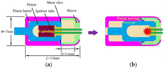
Figure 1.
Schematic illustration of working principle of propellant actuator: (a) the initial state, (b) the final state.
The propellant actuator is one of the common electric safety parts in the fuze. It locks the arming mechanism in a safe position and isolates the electric detonator from lead to ensure safety during assembly, transportation, storage, duty processing and launching. After the projectile launches, when it reaches the predetermined position, the fuze sends out the arming command and the propellant actuator is activated to service. At this moment, the explosive train is aligned, and the fuze is in a ready status.
The detailed working principle of the propellant actuator is described as follow: when the propellant actuator receives the arming signal, the electric ignition tube is detonated to generate high-pressure gas in order to push the piston downward. Then, the piston crushes or shears off the claws distributed in the circumferential direction of the shear slice, and the piston continues to move down to the end overcoming the friction of the cylinder wall so as to unlock the interrupter in the safety and arming device, as shown in Figure 1b.
3. Experimental Test
3.1. Experimental Method
In order to study the pressure–time characteristic of the propellant gas, an electrical measuring system of gas pressure was designed. In the measuring system, the resistance strain gauge was taken as the sensing element that was pasted on the outer surface of the propellant actuator, and it underwent deformation with the component when the propellant burnt and produced high-pressure gas in the inner cavity. Then, the strain at the measuring point would be determined and stored in the data acquisition instrument. Finally, according to Hooke’s Law, the pressure and the pressure–time characteristic curve of the propellant gas could both be calculated through data conversion and analysis. The schematic of the electrical measuring experiment was shown in Figure 2.

Figure 2.
Schematic of electrical measuring experiment.
3.2. Experimental Kit
The type of strain gauge is CHENG TEC 120-3AA, and it was pasted on the outer surface of the propellant actuator with No. 502 glue, as shown in Figure 3a. The strain gauge wires were connected to the bridge box (Figure 3b), which was used for the signal amplification, filtering and A/D conversion. The HBM GEN3i, a high-speed data acquisition instrument produced in Germany, was connected to the bridge box and used to collect and store the original data (shown in Figure 3c). The ignition wires connecting the electric ignition tube of the propellant actuator were connected to a detonator device that could provide an 800 volt pulse. Additionally, the charge of the propellant of the electric ignition tube was 12 mg, and the type of propellant in this experiment was Lead-2, 4, 6-trinitroresorcinate styphnate. The results of the experiment indicated that the detonator device detonated the electric ignition tube normally and the high-pressure gas pushed the piston downward. Eventually, the piston crushed or sheared off four claws distributed in the circumferential direction of the shear slice and moved down to the end. Figure 3d shows the pressure–time (p–t) curve of the propellant gas produced by the electric ignition tube in the propellant actuator cavity. According to the data of the curve, the rising edge time was about 94.1 μs and the peak value of pressure was about 53.9 MPa.
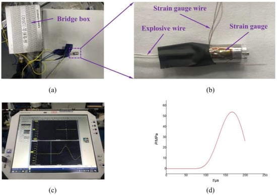
Figure 3.
(a) strain gauge, (b) bridge box, (c) HBM GEN3i, (d) experimental p–t curve of propellant gas.
4. Numerical Studies
4.1. Interior Ballistic Model
Basic assumptions of internal ballistic model [,,,]:
- (1)
- Propellant gas obeys the Nobel–Abel equation of state;
- (2)
- The combustion of the propellant follows the geometrical combustion law;
- (3)
- The gas components have the same physical and chemical parameters and gas phase velocity;
- (4)
- The composition of combustion products remains unchanged;
- (5)
- The influence of gas in the original cavity on combustion reaction, and heat loss and device deformation and gas loss are all ignored.
Firstly, taking the propellant gas produced by the electric ignition tube as the research object, the density and volume of the gas at a certain time (t) after initiation are set as ρt and Vt. After an increment time Δt, the density and volume would change into ρ and V. The increment of the density, volume and mass of the propellant gas are Δρ, ΔV = ΔV1 + ΔV2 and Δm, in which ΔV1 and ΔV2 are the piston movement and the increment of the propellant. In addition, the propellant density is ρp, the burning area of the propellant is Ab. The interior ballistic model of the piston movement of the propellant actuator was shown in Figure 4.
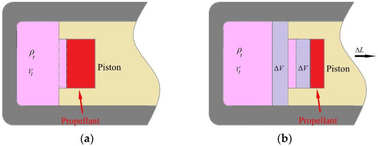
Figure 4.
The interior ballistic model of piston movement: (a) at a certain time t, (b) after an increment time Δt.
Based on the basic assumptions of the interior ballistic model and the classical interior ballistic equations, and combined with the special structural system of the propellant actuator, the interior ballistic equation of the propellant actuator is established, as shown in Equation (1) [,].
In which,
With boundary conditions,
where is the propellant burnt percentage, and are the propellant shape characteristic value, which is merely related to the shape and dimension of the propellant. Z is the relative burning thickness, p is the pressure in the chamber, v is the velocity of the piston, l is the travel of the piston, S is the cross-sectional area of the piston, f is the propellant force, is the mass of the propellant, is the mass of the piston [,,].
Obviously, Equation (1) is a system of ordinary differential equations composed of two algebraic equations and three differential equations, and it includes six variables such as If t is set as an independent variable, the equations are in closed forms and then the internal ballistic equations of the propellant actuator can be solved numerically employing the fourth-order Runge–Kutta method. The remaining calculation parameters are listed in Table 1.

Table 1.
Calculation parameters for interior ballistic model [,,,].
Based on the internal ballistic equations of the propellant actuator established above, the numerical calculation was carried out by using Matlab simulation software and the propellant gas pressure–time characteristic curve of the internal ballistic of the propellant actuator was obtained. The comparison between the simulation and the experiment was shown in Figure 5. It can be seen from Figure 5 that the trend of the simulation curve of the gas pressure–time characteristic is consistent with the experimental curve and the peak values are closed to each other. In addition, the characteristics of the pressure peak and the rising time are extracted from the comparison curves of simulation and experiment, as shown in Table 2. Clearly, they are in good agreement with each other, which could confirm the effectiveness of the internal ballistic model of the propellant actuator. In summary, the results demonstrate that the interior ballistic model of the propellant actuator is reasonable and accurate, and the pressure–time characteristic curve of propellant gas can be used as the working load of the propellant actuator for its structural optimization design.
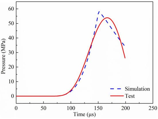
Figure 5.
Comparison between simulation and experiment.

Table 2.
Comparison of features between simulation and experiment.
4.2. Numerical Model of Propellant Actuator
The geometrical model of the main components of the propellant actuator were shown in Figure 6 and the damage of the shear slice was the focus of the follow-up studies.

Figure 6.
Geometrical model of propellant actuator.
The mesh discretization of the propellant actuator was mainly composed of three-dimensional hexahedral elements. The basic size of the mesh elements was 0.2 mm, with a total number of 103,559. The finite element model of the propellant actuator was shown in Figure 7, and the external view was shown in Figure 7a as well as the internal view in Figure 7b.
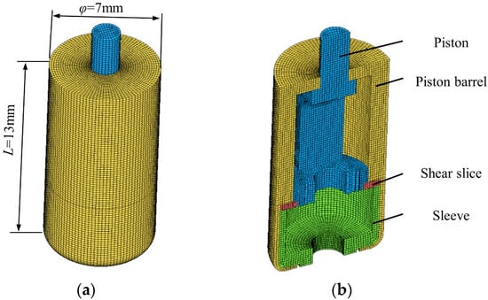
Figure 7.
Finite element model of propellant actuator: (a) external view, (b) internal view.
In this paper, the single-point integration algorithm was selected as the simulation algorithm of the numerical calculation model on account of its relatively high efficiency and accurate calculation accuracy. Meanwhile, contact surface-to-surface was chosen as the contact algorithm between the different parts. Moreover, the material adopted for all components of propellant actuator was 1Cr18Ni9Ti with a constitutive relationship plastic_kinematic, and the main constitutive parameters are shown in Table 3.

Table 3.
Main constitutive parameters [].
5. Results and Discussion
This part of the paper analyzes the mechanical response of the internal structure of the propellant actuator under two conditions consisting of the normal ignition and the accidental drop. According to the damage state of the shear slice, three typical damage modes were obtained, as shown in Figure 8. If the propellant actuator is normally detonated, the piston will be required to completely break through the constraints of the shear slice. Under this circumstance, the shear slice is in the best state of full plastic deformation or local fracture as shown in Figure 8b,c respectively. On the other hand, in case of the accidental drop, the piston will be required to be fully restrained by the shear slice, and the shear slice is expected to be in the state of no deformation or micro-deformation, as shown in Figure 8a.

Figure 8.
Three typical damage modes of shear slice: (a) micro-deformation, (b) full plastic deformation, (c) local fracture.
5.1. Analysis of Normal Ignition Condition
5.1.1. Typical Conditions
This section analyzes the typical working conditions of the propellant actuator during normal ignition from the perspective of processing and results. For the normal ignition condition, the piston was given a pressure–time characteristic curve of the propellant gas to simulate the movement and mechanical response of the piston during the ignition process, as shown in Figure 9a, and the specific pressure–time data were obtained from the interior ballistic model in Section 4.1 of this paper with the different charges of the propellant, as shown in Figure 9b.
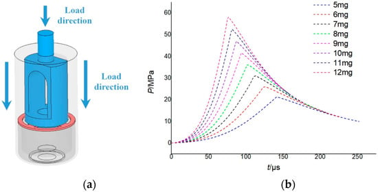
Figure 9.
Typical conditions: (a) load direction, (b) pressure–time curve used in simulations.
For the typical working conditions studied in this section, the charge of the propellant was 9 mg, and the shear slice thickness was 0.4 mm. The total duration of the simulation was 250 μs. Taking the ignition time as the initial time, the piston was in full contact with the shear slice at 64 μs; at 128 μs, significant plastic deformation of the claws distributed in the circumferential direction of the shear slice could be observed; at 200 μs, the piston completely broke through the restriction of the shear slice, leading to the noticeable local fracture claws of the shear slice. The complete movement process of the piston was shown in Figure 10. The stress distribution of the propellant actuator at a certain time was shown in Figure 10e. As can be seen from the figure, there mainly were two stress concentrations in the overall structure, which were located in the claws of the shear slice and the circular hole at the top of the piston barrel. The former stems from the axial impact between the piston and the shear slice in the process of movement, while the latter is mainly because of the transverse impact and friction between the piston and the piston barrel. Additionally, the stress values of the two stress concentration areas both exceed 200 MPa.
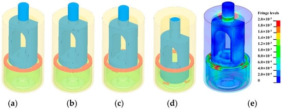
Figure 10.
Movement process of the piston: (a) t = 0 μs; (b) t = 64 μs; (c) t = 128 μs; (d) t = 200 μs; (e) stress distribution of propellant actuator at a certain time.
Figure 11 displays the displacement– and velocity–time history curves of the piston during the dynamic process. The simulation results show that, when the thickness of the shear slice was 0.4 mm, the propellant gas pressure generated by 5 mg or 6 mg failed to push the piston to overcome the restriction of the shear slice, as shown in Figure 11a. Furthermore, the gas pressure generated by 7 mg propellant succeeded in pushing the piston to break through the restriction of the shear slice, but it failed to move to the end of the piston barrel eventually, as shown in Figure 11b. On the other hand, the gas pressure generated by 8 mg and the larger amount of the propellant had no difficulty propelling the piston downward to the end. Consequently, a 7 mg charge would be the design boundary of the propellant charge for the 0.4 mm shear slice. More specifically, as shown in Figure 11b, when the charge of the propellant was 8 mg, the movement time of the piston was about 246 µs, and the maximum velocity was 33.87 m/s; when the charge was 9 mg, the movement time was about 210 µs and the maximum velocity was 44.40 m/s; when the charge was 10 mg, the movement time was about 196 µs and the maximum velocity was 53.04 m/s; when the charge was 11 mg, the movement time was about 176 µs and the maximum velocity was 59.84 m/s; when the charge was 12 mg, the movement time of was about 162 µs and the maximum velocity was 66.30 m/s. The simulation results clearly indicate that with the increasing amount of the propellant charge, the movement time of the piston decreases and the maximum velocity increases.
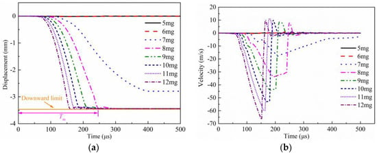
Figure 11.
Dynamic simulation results: (a) displacement–time history curve, (b) velocity–time history curve.
5.1.2. Optimization Analysis
In order to optimize the design of propellant actuator, the dynamic movement characteristics of the piston under different amounts of propellant charge and shear slice thickness were simulated by numerical calculation. Consequently, the amount of propellant charge ω and shear slice thickness hs were chosen as variables, and the maximum displacement of piston up was taken as the objective function, which is positive moving downward. The corresponding mathematical formulation of optimization analysis was
and the optimizing evaluation criteria was
Indicating that the optimized maximum displacement of the piston was larger than 3.06 mm. Specifically, the increment of the propellant charge was 1 mg with the total amount from 5 mg to 12 mg, and the increment of the shear slice thickness from was 0.1 mm from 0.2 mm to 0.5 mm. Moreover, the orthogonal optimizing method was adopted to perform the optimization analysis. The dynamic characteristics of the piston including the maximum velocity and the movement time is shown Figure 12, and the specific data is presented in Table 4. Note that “NAN” means the piston did not break through the constraint of the shear slice and reach the end of sleeve. It can be seen from Figure 12 and Table 3 that the gas pressure generated by 5 mg propellant barely pushed the piston to overcome the restriction of the shear slice with a thickness of 0.3 mm and a larger. In addition, the gas pressure generated by 6 mg and 7 mg propellant succeeded in pushing the piston to break through the constraint of shear slice with a thickness of 0.2 mm and 0.3 mm, but it failed to overcome the confinement of the shear slice with a thickness of 0.4 mm and a larger. What is more, the piston was propelled downward to the end under the gas pressure generated by 8 mg propellant and a larger amount. In summary, with increasing the propellant charge, the movement time of the piston decreases and the maximum displacement increases. Moreover, the critical values of propellant charge are 6 mg, 7 mg, 8 mg for the thickness of the shear slice 0.3 mm, 0.4 mm and 0.5 mm, respectively.
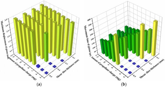
Figure 12.
Dynamic characteristics: (a) maximum displacement of piston, (b) movement time.

Table 4.
Specific data of dynamic characteristics.
5.2. Analysis of Accidental Drop Condition
5.2.1. Typical Conditions
This section analyzed the typical working conditions of the propellant actuator accidentally dropping to the ground from the perspective of processing and results. As a matter of fact, it is recognized that the propellant actuator dropping to the steel plate ground axially, as shown in Figure 13, would pose the most serious impact damage to the shear slice. As a consequence, the accidental drop of the propellant actuator in this section was carried out under this condition mentioned above.

Figure 13.
Axially accidental drop of propellant actuator.
Under the typical accidental drop condition studied in this section, the thickness of the shear slice was 0.3 mm, the initial drop height was 2 m, and the total time of simulation was 200 μs. The numerical result of the dropping process was shown in Figure 14. It can be seen that relative displacement between the piston and the shear slice could be observed, resulting in finite deformation of the shear slice yet without material failure, which prevented the piston from moving further to the bottom of the piston barrel. The stress distribution of the propellant actuator during the dropping process at a certain time was shown in Figure 14e. The results showed that there mainly were two stress concentrations in the overall structure, which were located in the claws of the shear slice and the circular hole at the top of the piston barrel. Similar to the normal ignition in Section 5.1.1, the former was due to the axial impact between the piston and the shear slice during the dropping process, while the latter came from the transverse impact and friction between the piston and the piston barrel.
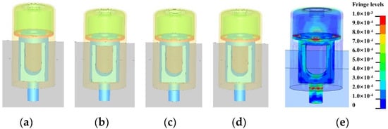
Figure 14.
Simulation process of accidental drop: (a) t = 0 μs, (b) t = 64 μs, (c) t = 128 μs, (d) t = 200 μs, (e) stress distribution of propellant actuator at a certain time.
5.2.2. Optimization Analysis
Taking the thickness of the shear slice as the variable, the dynamic characteristics of the piston when the propellant actuator accidentally dropped to the steel plate ground under the thickness of the shear slice from 0.2 mm to 0.5 mm were calculated, respectively. Similarly, the maximum displacement of the piston up was taken as the objective function, and the initial drop height hd and the shear slice thickness hs were chosen as variables. The corresponding optimization formulation of optimization analysis was
and the optimizing evaluation criteria was
Indicating that the optimized maximum displacement of piston was smaller than 3.06 mm. In addition, the increment of the shear slice thickness from was 0.1 mm, and the initial drop height was set to 2 because the maximum initial drop height corresponded to the rigorous standard. Furthermore, the orthogonal optimizing method was also adopted as to perform optimization analysis. As a consequence, the displacement–time curves of the piston were shown in Figure 15, and the local enlarged movement displacement–time curve of the piston, under the resistance of the shear slice from 0.3 mm to 0.5 mm, was shown in Figure 15b. When the thickness of the shear slice was 0.2 mm, the maximum displacement of the piston was 3.227 mm, larger than 3.06 mm. Moreover, the claws of the shear slice were sheared off, and then the piston moved downward to the end. On the other hand, when the thickness of the shear slice was 0.3 mm and larger, the claws of the shear slice all experienced finite plastic deformation, and the displacements of the piston were about 0.18 mm, 0.12 mm, 0.07 mm, respectively. To summarize, when accidentally dropping to the ground axially, the propellant actuator with 0.2 mm shear slice could not restrict the movement of the piston. Meanwhile, the propellant actuator with 0.3 mm shear slice and larger could confine the movement of the piston and ensure safety.
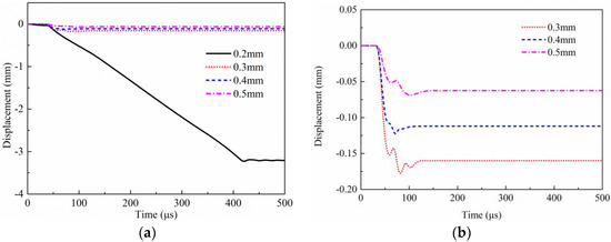
Figure 15.
Displacement–time curves of the piston during dropping process: (a) Overall curves, (b) Local enlarged curves.
6. Conclusions
At first, the pressure–time characteristic curve of the propellant gas was calculated using the internal ballistic model. On the basis of the characteristic curve, the dynamic characteristics of the piston under the different design configurations, including the thickness of the shear slice and amount of charge, were obtained by numerical simulation. In addition, the structure optimization design and accidental drop safety of the propellant actuator were conducted according to the finite element model of propellant actuator.
- (1)
- The total trend and the peak value of the simulation curve of the gas pressure–time characteristic obtained from the interior ballistic model of the propellant actuator were consistent with the experimental curve, with the peak error of 7.87% and the curve rise time error of 8.89%, revealing that the interior ballistic model of the propellant actuator is reasonable and accurate.
- (2)
- The simulation results demonstrated that the gas pressure generated by 5 mg propellant barely pushed the piston to overcome the restriction of the shear slice with a thickness of 0.3 mm and larger. Then, the gas pressure generated by 6 mg and 7 mg propellant succeeded in pushing the piston to break through the restriction of the shear slice with a thickness of 0.2 mm and 0.3 mm, but it failed to overcome the confinement of the shear slice with a thickness of 0.4 mm and larger. Last but not least, the gas pressure generated by 8 mg propellant and larger had no difficulty propelling the piston downward to the end.
- (3)
- When accidentally dropping to the ground axially, the propellant actuator with 0.2 mm shear slice could not confine the movement of the piston. On the other hand, the propellant actuator with 0.3 mm shear slice and larger could restrict the movement of the piston.
- (4)
- The propellant charge and the thickness of the shear slice cooperatively affect the dynamic feature of the actuator, and it is sensible to use more than 8 mg propellant of Lead-2, 4, 6-trinitroresorcinate styphnate in order to push the piston downward. Meanwhile, taking into account the safety requirements of transportation and service treatment, the thickness of the shear slice is not recommended to be less than 0.3 mm.
Author Contributions
Conceptualization: P.X., N.Z.; Methodology: P.X., K.S., C.C.; Software: P.X.; Validation: K.S., S.C., C.C.; Formal analysis: P.X., S.C.; Investigation: P.X.; Data Curation: N.Z.; Writing—Original draft preparation: P.X.; Writing—Review & Editing: S.C., C.C.; Supervision: N.Z., K.S.; Funding acquisition: J.L. All authors have read and agreed to the published version of the manuscript.
Funding
This research was funded by [Foundation of Science and Technology on Electromechanical Dynamic Control Laboratory, China] with grant number [6142601200111].
Institutional Review Board Statement
Not applicable.
Informed Consent Statement
Not applicable.
Data Availability Statement
Not applicable.
Acknowledgments
This work was supported by the Foundation of Science and Technology on Electromechanical Dynamic Control Laboratory, China (No. 6142601200111).
Conflicts of Interest
The authors declare no conflict of interest.
References
- Mu, H.; Luo, Y.; Luo, Y.; Chen, L. Numerical analysis of energy recovery of hybrid loader actuators based on parameters optimization. Actuators 2022, 11, 260. [Google Scholar] [CrossRef]
- Wang, L.; Jiang, Q.; Weng, Z.; Yuan, Q.; Wang, Z. Effects of flexural rigidity on soft actuators via adhering to large cylinders. Actuators 2022, 11, 286. [Google Scholar] [CrossRef]
- Jiao, Z.; Zhuang, Z.; Cheng, Y.; Deng, X.; Sun, C.; Yu, Y.; Li, F. Lightweight dual-mode soft actuator fabricated from bellows and foam materials. Actuators 2022, 11, 245. [Google Scholar] [CrossRef]
- Ida, E.; Mattioni, V. Cable-driven parallel robot actuators state of the art and novel servo-winch concept. Actuators 2022, 11, 290. [Google Scholar] [CrossRef]
- Fu, B.; Qi, H.; Xu, J.; Yang, Y. Composite sliding mode control of high precision electromechanical actuator considering friction nonlinearity. Actuators 2022, 11, 265. [Google Scholar] [CrossRef]
- Manca, R.; Puliti, M.; Circosta, S.; Galluzzi, R.; Salvatore, S.; Amati, N. Design and Optimization of an Active Leveling System Actuator for Lunar Lander Application. Actuators 2022, 11, 263. [Google Scholar] [CrossRef]
- Kalita, B.; Leonessa, A.; Dwivedy, S. A review on the development of pneumatic artificial muscle actuators: Force model and application. Actuators 2022, 11, 288. [Google Scholar] [CrossRef]
- Xie, S.; Zhang, J.; Chen, R. Miniaturized propellant actuator with interference fit between sliding pin and substrate. J. Detect. Control. 2018, 4, 116–121. [Google Scholar]
- Sun, J.; Guo, C.; Wu, R. Simulation research on the function process of the pin puller. Initiat. Pyrotech. 2017, 1, 10–13. [Google Scholar]
- Lu, J.; Zhang, S.; Yuan, L. An analysis on the combustion-kinetic process of retracting actuator. Initiat. Pyrotech. 1997, 1, 23–25+29. [Google Scholar]
- Briand, D.; Dubois, P.; Bonjour, L. Large deformation balloon micro-actuator based on pyrotechnics on chip. In Proceedings of the 2008 IEEE 21st International Conference on Micro Electro Mechanical Systems, Tucson, AZ, USA, 13–17 January 2008; IEEE: New York, NY, USA; pp. 535–538. [Google Scholar]
- Wu, Q.; Wen, Q.; Wang, Y. Theoretical analysis and simulation on pin moving process of explosive actuator. Initiat. Pyrotech. 2017, 1, 5–9. [Google Scholar]
- Lu, J.; Zhang, R.; Cui, W. Output parameters calculations and tests of piston actuator. Initiat. Pyrotech. 1996, 1, 13–16. [Google Scholar]
- Chen, J. Study on a Terminal Trajectory Correction Rocket and Its Fuze. Ph.D. Thesis, Nanjing University of Science and Technology, Nanjing, China, 2015. [Google Scholar]
- Wang, R.; Wang, Y.; Wang, C. Numerical simulation of the delay arming process of initiating explosive brakes. J. Beijing Inst. Technol. 2015, 24, 4–7. [Google Scholar]
- The 801st Teaching and Research Section in East China Institute of Technology. Internal Ballistics; East China Institute of Technology Press: Shanghai, China, 1986. [Google Scholar]
- Jin, Z. Interior Ballistics of Gun; Beijing Institute of Technology Press: Beijing, China, 2004. [Google Scholar]
- Zhang, X. Interior Ballistics of Gun; Beijing Institute of Technology Press: Beijing, China, 2014. [Google Scholar]
- Ye, Y.; Yan, N. Analysis of internal ballistic characteristics of low-impact unlocking bolt. J. Beijing Inst. Technol. 2012, 38, 1332–1336. [Google Scholar]
- Zhang, X.; Wang, Y. Analysis of dynamic characteristics for rarefaction wave gun during the launching. J. Appl. Mech. 2010, 77, 051601. [Google Scholar] [CrossRef]
- Luo, Q.; Zhang, X. Research for a projectile positioning structure for stacked projectile weapons. J. Appl. Mech. 2011, 78, 051015. [Google Scholar] [CrossRef]
- Zhang, X.; Zhou, W. Numerical simulation of interior ballistics processes of a high speed counter-mass pro pelling gun. In Proceedings of the 24th International Symposium on Ballistics, New Orleans, LA, USA, 22–26 September 2008; pp. 126–131. [Google Scholar]
- Zhang, R.; Yin, C.; Luo, X. The numerical analysis of the magnetorheological elastomer bulging for sheet metal. Procedia Manuf. 2020, 50, 110–113. [Google Scholar] [CrossRef]
Publisher’s Note: MDPI stays neutral with regard to jurisdictional claims in published maps and institutional affiliations. |
© 2022 by the authors. Licensee MDPI, Basel, Switzerland. This article is an open access article distributed under the terms and conditions of the Creative Commons Attribution (CC BY) license (https://creativecommons.org/licenses/by/4.0/).